EP3550246B1 - Rundumwärmetauscher - Google Patents
Rundumwärmetauscher Download PDFInfo
- Publication number
- EP3550246B1 EP3550246B1 EP19166756.7A EP19166756A EP3550246B1 EP 3550246 B1 EP3550246 B1 EP 3550246B1 EP 19166756 A EP19166756 A EP 19166756A EP 3550246 B1 EP3550246 B1 EP 3550246B1
- Authority
- EP
- European Patent Office
- Prior art keywords
- heat transfer
- connecting portion
- plates
- channel member
- conduit
- Prior art date
- Legal status (The legal status is an assumption and is not a legal conclusion. Google has not performed a legal analysis and makes no representation as to the accuracy of the status listed.)
- Active
Links
Images


Classifications
-
- F—MECHANICAL ENGINEERING; LIGHTING; HEATING; WEAPONS; BLASTING
- F28—HEAT EXCHANGE IN GENERAL
- F28D—HEAT-EXCHANGE APPARATUS, NOT PROVIDED FOR IN ANOTHER SUBCLASS, IN WHICH THE HEAT-EXCHANGE MEDIA DO NOT COME INTO DIRECT CONTACT
- F28D9/00—Heat-exchange apparatus having stationary plate-like or laminated conduit assemblies for both heat-exchange media, the media being in contact with different sides of a conduit wall
- F28D9/0031—Heat-exchange apparatus having stationary plate-like or laminated conduit assemblies for both heat-exchange media, the media being in contact with different sides of a conduit wall the conduits for one heat-exchange medium being formed by paired plates touching each other
- F28D9/0043—Heat-exchange apparatus having stationary plate-like or laminated conduit assemblies for both heat-exchange media, the media being in contact with different sides of a conduit wall the conduits for one heat-exchange medium being formed by paired plates touching each other the plates having openings therein for circulation of at least one heat-exchange medium from one conduit to another
- F28D9/0056—Heat-exchange apparatus having stationary plate-like or laminated conduit assemblies for both heat-exchange media, the media being in contact with different sides of a conduit wall the conduits for one heat-exchange medium being formed by paired plates touching each other the plates having openings therein for circulation of at least one heat-exchange medium from one conduit to another with U-flow or serpentine-flow inside conduits; with centrally arranged openings on the plates
-
- F—MECHANICAL ENGINEERING; LIGHTING; HEATING; WEAPONS; BLASTING
- F28—HEAT EXCHANGE IN GENERAL
- F28D—HEAT-EXCHANGE APPARATUS, NOT PROVIDED FOR IN ANOTHER SUBCLASS, IN WHICH THE HEAT-EXCHANGE MEDIA DO NOT COME INTO DIRECT CONTACT
- F28D21/00—Heat-exchange apparatus not covered by any of the groups F28D1/00 - F28D20/00
-
- F—MECHANICAL ENGINEERING; LIGHTING; HEATING; WEAPONS; BLASTING
- F28—HEAT EXCHANGE IN GENERAL
- F28D—HEAT-EXCHANGE APPARATUS, NOT PROVIDED FOR IN ANOTHER SUBCLASS, IN WHICH THE HEAT-EXCHANGE MEDIA DO NOT COME INTO DIRECT CONTACT
- F28D1/00—Heat-exchange apparatus having stationary conduit assemblies for one heat-exchange medium only, the media being in contact with different sides of the conduit wall, in which the other heat-exchange medium is a large body of fluid, e.g. domestic or motor car radiators
- F28D1/02—Heat-exchange apparatus having stationary conduit assemblies for one heat-exchange medium only, the media being in contact with different sides of the conduit wall, in which the other heat-exchange medium is a large body of fluid, e.g. domestic or motor car radiators with heat-exchange conduits immersed in the body of fluid
- F28D1/03—Heat-exchange apparatus having stationary conduit assemblies for one heat-exchange medium only, the media being in contact with different sides of the conduit wall, in which the other heat-exchange medium is a large body of fluid, e.g. domestic or motor car radiators with heat-exchange conduits immersed in the body of fluid with plate-like or laminated conduits
- F28D1/0308—Heat-exchange apparatus having stationary conduit assemblies for one heat-exchange medium only, the media being in contact with different sides of the conduit wall, in which the other heat-exchange medium is a large body of fluid, e.g. domestic or motor car radiators with heat-exchange conduits immersed in the body of fluid with plate-like or laminated conduits the conduits being formed by paired plates touching each other
- F28D1/035—Heat-exchange apparatus having stationary conduit assemblies for one heat-exchange medium only, the media being in contact with different sides of the conduit wall, in which the other heat-exchange medium is a large body of fluid, e.g. domestic or motor car radiators with heat-exchange conduits immersed in the body of fluid with plate-like or laminated conduits the conduits being formed by paired plates touching each other with U-flow or serpentine-flow inside the conduits
-
- F—MECHANICAL ENGINEERING; LIGHTING; HEATING; WEAPONS; BLASTING
- F28—HEAT EXCHANGE IN GENERAL
- F28D—HEAT-EXCHANGE APPARATUS, NOT PROVIDED FOR IN ANOTHER SUBCLASS, IN WHICH THE HEAT-EXCHANGE MEDIA DO NOT COME INTO DIRECT CONTACT
- F28D9/00—Heat-exchange apparatus having stationary plate-like or laminated conduit assemblies for both heat-exchange media, the media being in contact with different sides of a conduit wall
- F28D9/0081—Heat-exchange apparatus having stationary plate-like or laminated conduit assemblies for both heat-exchange media, the media being in contact with different sides of a conduit wall the conduits for one heat-exchange medium being formed by a single plate-like element ; the conduits for one heat-exchange medium being integrated in one single plate-like element
-
- F—MECHANICAL ENGINEERING; LIGHTING; HEATING; WEAPONS; BLASTING
- F28—HEAT EXCHANGE IN GENERAL
- F28F—DETAILS OF HEAT-EXCHANGE AND HEAT-TRANSFER APPARATUS, OF GENERAL APPLICATION
- F28F3/00—Plate-like or laminated elements; Assemblies of plate-like or laminated elements
- F28F3/12—Elements constructed in the shape of a hollow panel, e.g. with channels
-
- H—ELECTRICITY
- H10—SEMICONDUCTOR DEVICES; ELECTRIC SOLID-STATE DEVICES NOT OTHERWISE PROVIDED FOR
- H10W—GENERIC PACKAGES, INTERCONNECTIONS, CONNECTORS OR OTHER CONSTRUCTIONAL DETAILS OF DEVICES COVERED BY CLASS H10
- H10W40/00—Arrangements for thermal protection or thermal control
- H10W40/20—Arrangements for cooling
- H10W40/22—Arrangements for cooling characterised by their shape, e.g. having conical or cylindrical projections
-
- F—MECHANICAL ENGINEERING; LIGHTING; HEATING; WEAPONS; BLASTING
- F28—HEAT EXCHANGE IN GENERAL
- F28D—HEAT-EXCHANGE APPARATUS, NOT PROVIDED FOR IN ANOTHER SUBCLASS, IN WHICH THE HEAT-EXCHANGE MEDIA DO NOT COME INTO DIRECT CONTACT
- F28D1/00—Heat-exchange apparatus having stationary conduit assemblies for one heat-exchange medium only, the media being in contact with different sides of the conduit wall, in which the other heat-exchange medium is a large body of fluid, e.g. domestic or motor car radiators
- F28D1/02—Heat-exchange apparatus having stationary conduit assemblies for one heat-exchange medium only, the media being in contact with different sides of the conduit wall, in which the other heat-exchange medium is a large body of fluid, e.g. domestic or motor car radiators with heat-exchange conduits immersed in the body of fluid
- F28D1/04—Heat-exchange apparatus having stationary conduit assemblies for one heat-exchange medium only, the media being in contact with different sides of the conduit wall, in which the other heat-exchange medium is a large body of fluid, e.g. domestic or motor car radiators with heat-exchange conduits immersed in the body of fluid with tubular conduits
- F28D1/047—Heat-exchange apparatus having stationary conduit assemblies for one heat-exchange medium only, the media being in contact with different sides of the conduit wall, in which the other heat-exchange medium is a large body of fluid, e.g. domestic or motor car radiators with heat-exchange conduits immersed in the body of fluid with tubular conduits the conduits being bent, e.g. in a serpentine or zig-zag
- F28D1/0471—Heat-exchange apparatus having stationary conduit assemblies for one heat-exchange medium only, the media being in contact with different sides of the conduit wall, in which the other heat-exchange medium is a large body of fluid, e.g. domestic or motor car radiators with heat-exchange conduits immersed in the body of fluid with tubular conduits the conduits being bent, e.g. in a serpentine or zig-zag the conduits having a non-circular cross-section
-
- F—MECHANICAL ENGINEERING; LIGHTING; HEATING; WEAPONS; BLASTING
- F28—HEAT EXCHANGE IN GENERAL
- F28D—HEAT-EXCHANGE APPARATUS, NOT PROVIDED FOR IN ANOTHER SUBCLASS, IN WHICH THE HEAT-EXCHANGE MEDIA DO NOT COME INTO DIRECT CONTACT
- F28D1/00—Heat-exchange apparatus having stationary conduit assemblies for one heat-exchange medium only, the media being in contact with different sides of the conduit wall, in which the other heat-exchange medium is a large body of fluid, e.g. domestic or motor car radiators
- F28D1/02—Heat-exchange apparatus having stationary conduit assemblies for one heat-exchange medium only, the media being in contact with different sides of the conduit wall, in which the other heat-exchange medium is a large body of fluid, e.g. domestic or motor car radiators with heat-exchange conduits immersed in the body of fluid
- F28D1/04—Heat-exchange apparatus having stationary conduit assemblies for one heat-exchange medium only, the media being in contact with different sides of the conduit wall, in which the other heat-exchange medium is a large body of fluid, e.g. domestic or motor car radiators with heat-exchange conduits immersed in the body of fluid with tubular conduits
- F28D1/047—Heat-exchange apparatus having stationary conduit assemblies for one heat-exchange medium only, the media being in contact with different sides of the conduit wall, in which the other heat-exchange medium is a large body of fluid, e.g. domestic or motor car radiators with heat-exchange conduits immersed in the body of fluid with tubular conduits the conduits being bent, e.g. in a serpentine or zig-zag
- F28D1/0475—Heat-exchange apparatus having stationary conduit assemblies for one heat-exchange medium only, the media being in contact with different sides of the conduit wall, in which the other heat-exchange medium is a large body of fluid, e.g. domestic or motor car radiators with heat-exchange conduits immersed in the body of fluid with tubular conduits the conduits being bent, e.g. in a serpentine or zig-zag the conduits having a single U-bend
- F28D1/0476—Heat-exchange apparatus having stationary conduit assemblies for one heat-exchange medium only, the media being in contact with different sides of the conduit wall, in which the other heat-exchange medium is a large body of fluid, e.g. domestic or motor car radiators with heat-exchange conduits immersed in the body of fluid with tubular conduits the conduits being bent, e.g. in a serpentine or zig-zag the conduits having a single U-bend the conduits having a non-circular cross-section
-
- F—MECHANICAL ENGINEERING; LIGHTING; HEATING; WEAPONS; BLASTING
- F28—HEAT EXCHANGE IN GENERAL
- F28D—HEAT-EXCHANGE APPARATUS, NOT PROVIDED FOR IN ANOTHER SUBCLASS, IN WHICH THE HEAT-EXCHANGE MEDIA DO NOT COME INTO DIRECT CONTACT
- F28D1/00—Heat-exchange apparatus having stationary conduit assemblies for one heat-exchange medium only, the media being in contact with different sides of the conduit wall, in which the other heat-exchange medium is a large body of fluid, e.g. domestic or motor car radiators
- F28D1/06—Heat-exchange apparatus having stationary conduit assemblies for one heat-exchange medium only, the media being in contact with different sides of the conduit wall, in which the other heat-exchange medium is a large body of fluid, e.g. domestic or motor car radiators with the heat-exchange conduits forming part of, or being attached to, the tank containing the body of fluid
-
- F—MECHANICAL ENGINEERING; LIGHTING; HEATING; WEAPONS; BLASTING
- F28—HEAT EXCHANGE IN GENERAL
- F28D—HEAT-EXCHANGE APPARATUS, NOT PROVIDED FOR IN ANOTHER SUBCLASS, IN WHICH THE HEAT-EXCHANGE MEDIA DO NOT COME INTO DIRECT CONTACT
- F28D21/00—Heat-exchange apparatus not covered by any of the groups F28D1/00 - F28D20/00
- F28D2021/0019—Other heat exchangers for particular applications; Heat exchange systems not otherwise provided for
- F28D2021/0028—Other heat exchangers for particular applications; Heat exchange systems not otherwise provided for for cooling heat generating elements, e.g. for cooling electronic components or electric devices
- F28D2021/0029—Heat sinks
-
- F—MECHANICAL ENGINEERING; LIGHTING; HEATING; WEAPONS; BLASTING
- F28—HEAT EXCHANGE IN GENERAL
- F28D—HEAT-EXCHANGE APPARATUS, NOT PROVIDED FOR IN ANOTHER SUBCLASS, IN WHICH THE HEAT-EXCHANGE MEDIA DO NOT COME INTO DIRECT CONTACT
- F28D7/00—Heat-exchange apparatus having stationary tubular conduit assemblies for both heat-exchange media, the media being in contact with different sides of a conduit wall
- F28D7/0008—Heat-exchange apparatus having stationary tubular conduit assemblies for both heat-exchange media, the media being in contact with different sides of a conduit wall the conduits for one medium being in heat conductive contact with the conduits for the other medium
- F28D7/0025—Heat-exchange apparatus having stationary tubular conduit assemblies for both heat-exchange media, the media being in contact with different sides of a conduit wall the conduits for one medium being in heat conductive contact with the conduits for the other medium the conduits for one medium or the conduits for both media being flat tubes or arrays of tubes
- F28D7/0033—Heat-exchange apparatus having stationary tubular conduit assemblies for both heat-exchange media, the media being in contact with different sides of a conduit wall the conduits for one medium being in heat conductive contact with the conduits for the other medium the conduits for one medium or the conduits for both media being flat tubes or arrays of tubes the conduits for one medium or the conduits for both media being bent
-
- H—ELECTRICITY
- H05—ELECTRIC TECHNIQUES NOT OTHERWISE PROVIDED FOR
- H05K—PRINTED CIRCUITS; CASINGS OR CONSTRUCTIONAL DETAILS OF ELECTRIC APPARATUS; MANUFACTURE OF ASSEMBLAGES OF ELECTRICAL COMPONENTS
- H05K7/00—Constructional details common to different types of electric apparatus
- H05K7/20—Modifications to facilitate cooling, ventilating, or heating
- H05K7/20218—Modifications to facilitate cooling, ventilating, or heating using a liquid coolant without phase change in electronic enclosures
- H05K7/20254—Cold plates transferring heat from heat source to coolant
-
- H—ELECTRICITY
- H10—SEMICONDUCTOR DEVICES; ELECTRIC SOLID-STATE DEVICES NOT OTHERWISE PROVIDED FOR
- H10W—GENERIC PACKAGES, INTERCONNECTIONS, CONNECTORS OR OTHER CONSTRUCTIONAL DETAILS OF DEVICES COVERED BY CLASS H10
- H10W40/00—Arrangements for thermal protection or thermal control
- H10W40/40—Arrangements for thermal protection or thermal control involving heat exchange by flowing fluids
- H10W40/47—Arrangements for thermal protection or thermal control involving heat exchange by flowing fluids by flowing liquids, e.g. forced water cooling
Definitions
- a heat transfer fluid such as a circulated liquid or gas.
- US 2016/0234975 A1 relates to a heat exchanger for cooling an electric element and a heat exchanger assembly for cooling an electric element capable of facilitating an insertion of the electric element and improving cooling performance by contacting both side surfaces of the electric element and a tube in which cooling water flows to each other.
- US 2015/0200429 A1 relates to a battery module including a flexible heat dissipating unit and US 2005/0040515 A1 to a coolant cooled type semiconductor device.
- aspects of the invention provide for an assembly for transferring heat with respect to a component
- the assembly includes a first heat transfer plate having a first surface arranged to contact and transfer heat with respect to a first component surface, and a second heat transfer plate having a second surface arranged to contact and transfer heat with respect to a second component surface.
- the first and second component surfaces may be surfaces of the same component, or of different components, and the component(s) may be any device with which heat is to be transferred, such as electronic devices, surfaces of a cold plate or other heat exchanger configuration, and so on.
- the second heat transfer surface may face the first heat transfer surface, i.e., generally toward the first heat transfer surface and be oriented so that the second heat transfer surface is arranged at an angle of 90 degrees or less relative to the first heat transfer surface.
- the heat transfer surfaces may be arranged at angles up to 180 degrees or more relative to each other.
- a connecting portion may extend between and connect the first and second heat transfer plates together, with the connecting portion providing compliant support of the first and second heat transfer plates that allows the first and second heat transfer surfaces to be movable toward and away from each other.
- the connecting portion may include a bend that extends along an arc of at least 90 degrees so the heat transfer surfaces are arranged facing each other.
- the connecting portion may provide an elastically deformable section between the heat transfer plates that allows the plates to be moved relative to each other, at least to some extent, without causing plastic deformation of the elastically deformable element. This may allow the connecting portion to exert a bias on the plates, e.g., to urge the plates to move toward each other when the plates are engaged with a component surface.
- the connecting portion may have a part that plastically deforms or is plastically deformable when the heat transfer plates are moved relative to each other, and such plastic deformation may be used alone or in combination with elastic deformation.
- a heat transfer conduit may be arranged to conduct a flow of heat transfer fluid to the first and second heat transfer plates, with the heat transfer conduit including at least one passageway that extends from the first heat transfer plate to the connecting portion, and from the connecting portion to the second transfer plate.
- Inlet and outlet ports may be arranged to respectively conduct heat transfer fluid into the heat transfer conduit and out of the heat transfer conduit, e.g., so that heat transfer fluid can be circulated to the heat transfer plates to receive heat from the plates.
- the first and second heat transfer plates may each have a side respectively opposite of the first and second heat transfer surfaces that are exposed for contact with heat transfer fluid in the heat transfer conduit, e.g., to transfer heat with respect to the heat transfer fluid.
- the first and second heat transfer plates and at least a part of the connecting portion may be formed as a single unitary part, e.g., the single unitary part may be a metal sheet formed to define the first and second heat transfer plates and at least a part of the connecting portion.
- the metal sheet may be flat, at least initially, such as at a time when the heat transfer plates and connecting portion are cut from the sheet.
- a channel member that at least partially defines the heat transfer conduit and at least a part of the connecting portion may be secured to single unitary part.
- the channel member may be secured to the single unitary part such that the single unitary part and the channel member together define at least a portion of the heat transfer conduit.
- the channel member may be formed as a "blister" element, e.g., a relatively thin sheet material that is bent, stamped or otherwise formed to define concave regions that function as the heat transfer conduit once closed by the single unitary part or other element.
- the channel member and the single unitary part may each have a periphery, and the peripheries of the channel member and the single unitary part may be sealingly joined together, such as by brazing or welding. This attachment of the channel member and the unitary part may enclose the heat transfer conduit portions defined by the channel member, allowing the heat transfer conduit to conduct fluid flow.
- the inlet port is located adjacent the first heat transfer plate, and the outlet port is located adjacent the second heat transfer plate.
- a channel member may define an inlet and/or outlet port, and the inlet or outlet port may be located adjacent a corresponding heat transfer plate. This may allow fluid that enters the inlet to be directed toward the first heat transfer plate for contact with the plate, and/or fluid that contacts the second heat transfer plate to move directly to the outlet.
- an inlet (or outlet) that is adjacent to a heat transfer plate may be defined at least in part by the heat transfer plate, or the inlet (or outlet) may be defined by another component that is positioned near to the plate, such as a channel member.
- the heat transfer conduit may be arranged to conduct flow to the heat transfer plates in a variety of different ways.
- the heat transfer conduit and the inlet and outlet ports may be arranged such that heat transfer fluid flows from the first heat transfer plate to the second heat transfer plate and back to the first heat transfer plate before exiting the heat transfer conduit via the outlet port.
- fluid may flow from the first heat transfer plate to the second heat transfer plate and then exit via the outlet.
- fluid entering an inlet may split with one portion of the fluid flowing to a first heat transfer plate and another portion of the fluid flowing to a second heat transfer plate. Other flow configurations are possible.
- the heat transfer plates may contact corresponding surfaces of a component, and the plates may be secured relative to each other and/or relative to the corresponding component surface.
- at least one fastener may urge the first and second heat transfer plates to move toward each other to secure a component between the first and second heat transfer plates.
- a fastener may include a clamp, nut and bolt, bail, hook, bayonet pin, threaded fastener, rivet, or other suitable arrangement.
- a method for forming an assembly for transferring heat with respect to a component includes providing first and second heat transfer plates respectively having first and second surfaces arranged to contact and transfer heat with respect to first and second component surfaces.
- the first and second heat transfer plates may be connected by a connecting portion extending between the first and second heat transfer plates.
- the first and second heat transfer plates are part of a single unitary part that defines the first and second heat transfer plates and at least part of the connecting portion.
- a channel member may be secured to the unitary part such that the channel member and the unitary part define at least in part a heat transfer conduit that can conduct fluid flow to the heat transfer plates.
- the channel member has a concave portion that defines at least in part the heat transfer conduit and a peripheral edge, and the channel member may be secured to the unitary part by sealingly securing the peripheral edge of the channel member to the single unitary part so that the channel member and the single unitary part together enclose the heat transfer conduit.
- the connecting portion may be bent so that the second heat transfer surface faces the first heat transfer surface and is arranged at an angle of 90 degrees or less relative to the first heat transfer surface.
- the bent connecting portion may also provide compliant support of the first and second heat transfer plates that allows the first and second heat transfer surfaces to be movable toward and away from each other, e.g., so the plates can move as needed when contacting a corresponding component surface.
- a heat transfer conduit mentioned above may be arranged to conduct a flow of heat transfer fluid to the first and second heat transfer plates, with the heat transfer conduit including at least one passageway that extends from the first heat transfer plate to the connecting portion and from the connecting portion to the second transfer plate.
- Inlet and outlet ports may be arranged to respectively conduct heat transfer fluid into the heat transfer conduit and out of the heat transfer conduit.
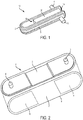
- FIG. 1 shows a wrap around heat exchanger assembly 10 for transferring heat with respect to one or more components 20.
- the assembly 10 is arranged to engage with and cool two or more heat generating components 20, such as power electronics, computer processors, batteries, and other devices that generate heat.
- heat generating components 20 such as power electronics, computer processors, batteries, and other devices that generate heat.
- use of the assembly 10 for cooling is not required, as any heat transfer may be employed by the assembly 10, including heating of a component 20 by the assembly 10.
- a component 20 need not be or include an electronic device, but may be any device requiring cooling and/or heating.
- the assembly 10 may have a variety of different shapes, sizes or other configurations, some embodiments of which are described below. In this illustrative embodiment of FIG.
- the assembly 10 includes first and second heat transfer plates 1a and 1b that each have a heat transfer surface that contacts a portion of a component 20.
- the heat transfer plates 1 may be made of a metal, such as aluminum or copper, or any other suitable material to transfer heat with respect to a component 20.
- the heat transfer plates 1 may each contact a respective heat generating portion of the component 20 so that heat generated by the component 20 may be received by the plates 1, thereby cooling the component 20.
- thermal grease or other thermal coupling agent may be used between the heat transfer surfaces and the component surfaces.
- heat transfer plates 1 contact opposite sides of a single component 20, but other arrangements are possible, such as having the first heat transfer plate 1a contact a surface of a first component 20, and having the second heat transfer plate 1b contact a surface of a second component 20 which is stacked on top of the first component 20. Alternately, two or more components 20 may be placed side-by-side so the first and second heat transfer plates 1 contact opposite sides of both components 20.
- the assembly wraps around at least a portion of one or more components 20 that is engaged by the assembly 10.
- the plates 1 are supported by a connecting portion 2 extending between and connecting the first and second heat transfer plates 1a, 1b.
- the connecting portion 2 may provide compliant support of the first and second heat transfer plates 1a, 1b that allows the first and second heat transfer surfaces to be movable toward and away from each other in an elastic way, i.e., so the heat transfer surfaces can be moved toward or away from each other in the presence of a force, but will recover to a rest position when the force is removed.
- the connecting portion 2 supports the heat transfer plates 1 so the plates 1 can be moved apart to receive a component 20 between the plates 1 and/or so the plates 1 can be moved towards each other to engage one or more components 20.
- the connecting portion 2 may support the plates 1 in an at rest condition so that a distance between the plates 1 is smaller than a dimension of the component 20 to be positioned between the plates.
- the connecting portion 2 may support the plates 1 so the plates can be moved apart to receive the component 20.
- the connecting portion 2 may bias the plates 1 to move toward each other with a resilient force, e.g., so that the component 20 may be squeezed by the plates 1.
- a resilient force e.g., so that the component 20 may be squeezed by the plates 1.
- the plates 1 may be supported by the connecting portion 2 in an at rest condition so that a distance between the plates 1 is greater than a dimension of the component 20 to be positioned between the plates 1. This arrangement may provide for easier positioning of the component 20 between the plates 1 since the plates 1 need not be moved apart.
- the plates 1 may be clamped or otherwise moved toward each other to engage the component 20, e.g., by a clamp or other fastener that engages with the plates 1 and/or the connecting portion 2 to bias the plates 1 to move toward each other, or by fasteners that secure the plates 1 to each other and/or to the component 20.
- a spring clip may be engaged over the connecting portion 2 and/or over the plates 1 so that the spring clip urges the plates 1 to move toward each other.
- a bolt may extend through openings in the plates 1 and/or connecting portion 2 and a nut may be engaged with the bolt to move the plates 1 toward each other and secure the plates 1 to the component 20.
- Other arrangements are possible, such as adhesive, welding, brazing and other fastener configurations.
- the heat exchanger assembly 10 can include a heat transfer conduit 5 to conduct a flow of heat transfer fluid for contact with the heat transfer plates 1. That is, heat may be received from, or provided to, the heat transfer plates 1 by a heat transfer fluid that may be circulated through the assembly 10.
- a heat transfer conduit 5 can include at least one passageway that extends from the first heat transfer plate 1a to the connecting portion 2 and from the connecting portion 2 to the second transfer plate 1b and conducts a flow of heat transfer fluid to and/or between the first and second heat transfer plates 1a, 1b.
- Inlet and outlet ports 3,4 may be arranged to respectively conduct heat transfer fluid into the heat transfer conduit 5 and out of the heat transfer conduit 5, respectively.
- the heat transfer fluid may transfer heat with respect to the heat transfer plates 1, e.g., provide heat to and/or receive heat from the plates 1.
- the heat transfer fluid may contact a side of the plates 1 that is opposite a side of the plates that contacts a component 20, i.e., the heat transfer surface.
- heat received by a plate 1 from a component on one side of the plate 1 may be transferred by the plate 1 to heat transfer fluid on an opposite side of the plate 1.
- the fluid may be a gas, liquid, a combination of gas and liquid, or have any other suitable arrangement.
- the heat transfer conduit 5 may include a plurality of passageways that extend from the inlet to the outlet port 3,4, e.g., for parallel flow of heat transfer fluid in the passageways between the plates 1a,1b, or for serial flow in the passageways between the plates 1a,1b.
- heat transfer fluid may enter an inlet port 3, and flow to the first heat transfer plate 1a, and then flow to the second heat transfer plate 2b and exit via the outlet port 4.
- Such flow may be achieved in a single passageway or in multiple passageways that allow for parallel flow from one plate 1 to the other plate 1.
- fluid may flow from the inlet port 3 to the first plate 1a, then to the second plate 1b, then back to the first plate 1a, then back to the second plate 1b, (optionally repeating this flow pattern one or more times) and then exit via the outlet port 4.
- the heat transfer conduit 5 may include one or more passageways that provide for serial flow from a first plate 1 to a second plate 1, back to the first plate 1, then to the second plate 1, and so on.
- Heat exchanger assemblies 10 are not limited to just this type of fluid flow, however.
- fluid may enter the inlet port 3 and flow either to the first plate 1a or the second plate 1b, e.g., the heat transfer conduit 5 may split flow of the incoming fluid at the inlet 3 so some fluid flows directly to the first plate 1a and other fluid flows directly to the second plate 1b. Thereafter, the fluid may exit via an outlet port 4.
- the heat transfer conduit 5 may split flow of the incoming fluid at the inlet 3 so some fluid flows directly to the first plate 1a and other fluid flows directly to the second plate 1b. Thereafter, the fluid may exit via an outlet port 4.
- an assembly 10 is not limited to one inlet port 3 and one outlet port 4, and instead may have any suitable number of such ports 3,4 and the ports 3,4 may be positioned in any suitable way or location on the assembly 10, including on the connecting portion 2.
- each heat transfer plate 1 may have a corresponding inlet 3, outlet 4 and heat transfer conduit 5, e.g., so fluid enters the inlet 3, contacts the plate 1 only, and then exits via the outlet 4.
- the connecting portion 2 may provide only mechanical support and connection between the plates 1, with no heat transfer conduit 5 extending along the connecting portion 2.
- an inlet 3 may be provided at the connecting portion 2, and incoming fluid flow may be split so a portion of the fluid flows to a first heat transfer plate 1a, and another portion of the fluid flows to a second heat transfer plate 1b.
- Outlets 4 may be provided adjacent each heat transfer plate 1, e.g., in a way like that shown in FIG.
- the heat transfer surface of one heat transfer plate e.g., the second heat transfer plate 1b in FIG. 1
- the heat transfer surfaces of the heat transfer plates 1a, 1b are arranged at an angle of about 0 degrees relative to each other, e.g., an angle of 5 degrees or less.
- a configuration where the plates 1a, 1b are spaced apart and in generally parallel planes (i.e., at an angle of about 0 to 5 degrees to each other) may allow the assembly 10 to sandwich a component 20 that has heat generating surfaces on opposite, parallel sides of the component 20.
- an assembly 10 may be arranged in other ways to engage other component 20 surface configurations.
- a component 20 may have heat generating surfaces arranged at an angle of 5 to 90 degrees to each other.
- an assembly 10 may have first and second heat transfer plates 1a, 1b that have heat transfer surfaces arranged at about 5 to 90 degrees to each other so that each plate 1a, 1b may contact a corresponding heat generating surface of the component 20.
- the 1 embodiment may support the heat transfer plates 1a,1b so that their heat transfer surfaces face each other and are arranged at an angle of 45 degrees to each other so the heat transfer surfaces can engage with surfaces of a component 20 that are at an angle of 45 degrees.
- the plates 1a, 1b may be supported by the connecting portion 2 so the heat transfer surfaces are at an angle less than that of the component surfaces, e.g., so that the plates 1a, 1b may squeeze or resiliently contact the heat generating surfaces of the component 20 when the assembly is engaged with the component 20.
- a clamp or other fastener may be used to secure the plates 1a, 1b to the component 20.
- FIG. 2 shows an exploded view of an assembly 10 that may ultimately be configured like that in FIG. 1 .
- the first and second heat transfer plates 1a, 1b and at least a part of the connecting portion 2 are formed as a single unitary part 9.
- the single unitary part 9 may be a flat metal sheet formed to define the first and second heat transfer plates 1a, 1b and at least a part of the connecting portion 2.
- the metal sheet material may be die cut or otherwise formed to have the desired shape for the plates 1a, 1b and the connecting portion 2 and then mated with another part to define the heat transfer conduit 5 and inlet and outlet ports 3,4.
- a channel member 6 is arranged to mate with the unitary part 9 and to at least partially define the heat transfer conduit 5 and at least a part of the connecting portion 2.
- the channel member 6 may be formed from a sheet material that is bent, stamped or otherwise shaped to define one or more concave sections or "blisters" that define part of the heat transfer conduit 5. Elements arranged in this way to provide a fluid passageway by bending or otherwise forming a relatively thin sheet material are described in more detail in US Patents 6661658 and 8616267 , which are hereby incorporated by reference.
- the channel member 6 may be cut, ground, skived or otherwise machined to have material removed so as to define the heat transfer conduit 5.
- the channel member 6 may be secured to the single unitary part 9 such that the single unitary part and the channel member together define or enclose at least a portion of the heat transfer conduit 5.
- the channel member 6 and the single unitary part 9 may each have a periphery, and the peripheries of the channel member 6 and the single unitary part 9 may be sealingly joined together, e.g., by brazing, welding, adhesive, fasteners, etc., e.g., as shown in FIG. 3 .
- the channel member 6 may include the inlet and outlet ports 3,4 and the channel member 6 may extend from the first heat transfer plate 1a to the second heat transfer plate 1b along the connecting portion 2.
- the channel member 6 and the unitary part 9 may be bent to form an arrangement like that in FIG. 4 .
- manufacture and assembly may be made easier and less costly.
- the channel member 6 and unitary part 9 may be bent before being assembled together, and the bent parts joined together, e.g., to enclose and define the heat transfer conduit 5. It should be understood, however, that not all embodiments need have the connecting portion 2 mechanically bent, whether before or after component parts are joined together to form the connecting portion 2.
- the connecting portion 2 may be molded (e.g., of a polymer material, which may include a rubber, elastomer, thermoset, thermoplastic, fiber reinforced polymer, and other materials or combinations of materials), machined from a block, or otherwise formed to have a desired curved or otherwise bent shape.
- heat transfer plates 1 may be formed of metal sheets that are placed into a molding cavity and co-molded with a polymer material that forms the connecting portion 2, heat transfer conduit 5 and inlet and outlet ports 3,4.
- a bend feature of a connecting portion 2 need not be formed by a mechanical bending process, but rather a component that includes a bend may be molded, machined or otherwise formed to have the bend without mechanical bending.
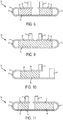
- the heat transfer plates 1 may be engaged with one or more components 20, e.g., as shown in FIGs. 4 and 5 .
- three components 20 are sandwiched between the first and second heat transfer plates 1a, 1b, but any suitable number of components 20 may be employed.
- one or more clamps 8 are arranged to engage with the peripheries of the channel member 6 and the heat transfer plates 1 so as to clamp the components 20 between the plates 1.
- other fastener arrangements are possible as discussed above, such as screw-type or other fasteners, adhesive, welding, etc.
- peripheral portions of the first and second heat transfer plates 1a,1b may each have a hole or other opening through which a bolt, spring pin, bayonet pin or other fastener can extend to secure the plates 1 relative to each other and to a component 20.
- FIGs. 6 and 7 show yet another embodiment in which one or more fasteners 8 are formed integrally with or otherwise attached to a heat exchanger assembly 10.
- the fasteners 8 are straps, arms, hooks or bails that extend outwardly from the first heat transfer plate la.
- the fasteners 8 may be formed integrally with the heat transfer plate 1a, e.g., may be cut from a sheet material with the heat transfer plate 1a.
- the fasteners 8 can be extended from the first heat transfer plate 1a to the second heat transfer plate 1b, e.g., after a component 20 is positioned between the plates 1.
- the fasteners 8 may engage with the second heat transfer plate 1b (either directly or indirectly via a part of an adjacent channel member 6) in any suitable way.
- the fasteners 8 in FIG. 7 may be bent to form a hook that captures part of the second heat transfer plate 1b or other assembly portion 10 (such as the outlet 4).
- fasteners 8 may be welded, brazed or adhered, secured by threaded fastener, and so on.
- fasteners 8 may be provided for both heat transfer plates 1a,1b, and the fasteners 8 may be secured to each other, e.g., in a buckle and strap arrangement, by welding or screwing the straps to each other, and so on.
- ramp features 13 that extend from short sides of the heat transfer plates 1a, 1b.
- the ramps 13 may aid in positioning a component 20 between the heat transfer plates 1a,1b, particularly if the assembly 10 is formed so that a distance between the plates 1 is less than a dimension of a component 20 to be positioned between the plates.
- the ramps 13 may allow the assembly 10 to be pushed onto the component 20 so the ramps 13 contact the component 20 and urge the plates 1 away from each other to allow the component 20 to be positioned between the plates 1.
- the ramps 13 may be provided in any suitable way, such as formed integrally with the plates 1 as shown, or formed separately and attached to the plates 1, or provided as an unattached element that is used to engage a component 20 and then removed after use. Also, ramps 13 may be provided on any part or parts of an assembly 10, not just on the short side of heat transfer plates 1 as shown.
- the heat transfer plates 1 may themselves include an inlet and/or outlet port 3,4 and/or may define at least a part of the heat transfer conduit 5.
- the plates 1 may include internal channels to define at least parts of the heat transfer conduit 5, and each plate 1 may have an inlet 3 and/or outlet 4 to conduct flow of fluid into or out of the internal channels.
- the internal channels of the plates 1 may be fluidly coupled by a connecting portion 2 that includes one or more passageways.
- the connecting portion 2 may be formed by one or more tubes that are mechanically and fluidly coupled to the plates 1 so that the tubes provide a fluid connection for the heat transfer conduit 5 as well as mechanical support for the plates 1.
- a side of the heat transfer plates 1 that contacts the heat transfer fluid may include pins, fins, grooves or other structure to help increase a surface area of the plate 1 and thus aid in heat transfer with the heat transfer fluid.
- a side of the plates 1 that contacts a component 20 may include dimples, grooves, raised structures, pins, fins, and/or other structure to engage with a component 20. Such structure may help increase a contact area, and thus aid in heat transfer, or may provide other functions such as helping to secure the component 20 to the plate 1.
- the connecting portion 2 and portion of the heat transfer conduit 5 at the connecting portion 2 may be arranged to transfer heat in any suitable way.
- the connecting portion 2 may be arranged to receive heat from the heat transfer fluid and release that heat to an exterior environment, e.g., by receiving heat from the fluid that is then releasing the heat via fins, pins or other structure on the connecting portions 2 to air or other external environmental features.
- the connecting portion 2 may be arranged to reduce heat transfer between the fluid and the connecting portion 2.
- the heat transfer conduit 5 and/or the connecting portion 2 may be thermally insulated or made of a thermally insulating material to reduce heat transfer between the heat transfer fluid and the connecting portion 2, and/or between the connecting portion 2 and an exterior environment.
- a flow rate of fluid and/or a cross sectional area of the heat transfer conduit 5 may be arranged as desired in the connecting portion 2 to achieve desired flow rate, heat transfer or other characteristics.
- the heat transfer conduit 5 in a part of the connecting portion 2 may have a smaller cross sectional area than in areas near the heat transfer plates 1. This feature can be seen in FIGs. 3 and 4 , for example.
- the smaller cross sectional area at the connecting portion 2 may have different desired effects, such as helping increase (or decrease) a flow rate of heat transfer fluid in the connecting portion 2, increasing (or decreasing) a contact area between the heat transfer fluid and the connecting portion 2, increasing (or decreasing) turbulence of flow through the connecting portion 2, increasing (or decreasing) resistance to flow, and so on.
- the process of bending the connecting portion 2 e.g., formed by a channel member 6 and unitary part 9 as in FIG. 2 ) may narrow the heat transfer conduit 5 in the connecting portion 2.
- Standoff elements such as ribs, fins or walls may be provided between the channel member 6 and the unitary part 9 in the connecting portion 2 to help the heat transfer conduit 5 have a minimum or defined dimension in at least one direction (e.g., a radial direction in relation to the curve of the bend).
- the heat transfer conduit 5 in a part of the connecting portion 2 may have a larger cross sectional area than in areas near the heat transfer plates 1.
- FIGs. 8-11 show alternatives of the FIG. 1-7 embodiments.
- FIG. 8 shows an assembly that includes two connecting portions 2 and three heat transfer plates 1a, 1b and 1c. While the embodiment in FIG. 8 is shown employed with two components 20, it may be used with two or more components 20 as shown in FIG. 9.
- FIGs. 8 and 9 also share the feature that the inlet 3 and outlet 4 are arranged on a same side of the assembly 10 and extend in a same general direction, which may provide for easier connection to a heat transfer fluid supply.
- FIG. 10 shows another embodiment with inlet 3 and outlet 4 that extend in a same direction, but in this case the outlet 4 is arranged on the second heat transfer plate 1b rather than on a channel member 6 or other similar element.
- FIG. 10 also has heat transfer plates 1 with different sizes, e.g., length, area, width, etc. Heat exchange assemblies are not limited to arrangements having heat transfer plates 1 of similar size or other configuration details.
- FIG. 11 shows another modification of the FIG. 8 embodiment where a first heat transfer plate 1a is shorter than a third heat transfer plate 1c.
- heat transfer plates 1 may be arranged in any suitable way relative to each other.
- the embodiments in FIGs. 8-11 may be made in a way similar to that shown in FIGs. 2-5 or in any other suitable way.
- FIG. 12 shows an assembly 10 that includes two pairs of opposed or otherwise facing heat transfer plates 1a and 1b, and 1c and 1d, and one or more components 20 may be positioned between the heat transfer plates 1a, 1b, and another one or more components 20 in a different plane may be positioned between the heat transfer plates 1c, 1d.
- this embodiment shows heat transfer plates 1 with heat transfer surfaces arranged in parallel planes, plates 1 and/or heat transfer surfaces may be arranged at non-zero angles relative to each other.
- an inlet 3 may be provided adjacent a first heat transfer plate 1a, and an outlet 4 may be provided adjacent a fourth heat transfer plate 1d, but other configurations are possible.
- additional inlets 3 and outlets 4 may be provided as shown in dashed line in FIG. 12 , i.e., an additional outlet 4 positioned adjacent the second heat transfer plates 1b, and an additional inlet 3 positioned adjacent the third heat transfer plates 1c.
- the heat transfer conduit 5 need not extend between the second and third plates 1b,1c as shown, but instead each pair of plates 1a,1b and 1c,1d may have a corresponding heat transfer conduit 5 that do not communicate with each other.
- other inlet and outlet 3, 4 arrangements are possible.
- Connecting portions 2 may provide compliant support of the plates 1a-1d so that a component 20 can be squeezed between pairs of plates 1a, 1b or 1c, 1d by a resilient force.
- one or more clamps, fasteners or other structure may engage the plates 1 to force the pairs of plates 1a, 1b or 1c, 1d to move toward each other.
- the assembly 10 may be made in a way like that shown in FIGs.
- a first metal sheet may be arranged to form the first and second heat transfer plates 1a, 1b as well as a channel member 6 for the third and fourth heat transfer plates 1c, 1d
- a second metal sheet may be arranged to form the third and fourth heat transfer plates 1c, 1d as well as a channel member 6 for the first and second heat transfer plates 1a, 1b.
- the two metal sheets may be secured together at peripheries, and then bent to form the two connecting portions 2 in a way similar to that described above.
- other assembly arrangements may be used to form the assembly 10 in FIG. 12 .
- two separate assemblies arranged similar to that in FIGs. 2-5 may be constructed, and the two assemblies joined together to form the assembly 10 of FIG. 12 .
- FIG. 13 shows a modified version of the FIG. 12 embodiment that includes five pairs of opposed or otherwise facing heat transfer plates 1, although other numbers of pairs of plates 1 can be employed.
- one or more components 20 may be positioned between a corresponding pair of plates 1, and the plates 1 may be engaged with a corresponding component 20 by a resilient force exerted on the plates by the connecting portion 2, one or more fasteners, etc. that urge the plates 1 to move toward each other.
- the assembly 10 includes one or more heat transfer plates 1 that do not have an opposed or otherwise facing plate 1.
- portions of the assembly indicated by the reference number 11 in FIG. 13 may function as a heat transfer plate 1, e.g., for contact and heat transfer with one side of a component 20.
- the unpaired heat transfer plates 11 may be associated with an unpaired heat transfer plate 11 of another assembly 10 such that the two unpaired heat transfer plates 11 can sandwich one or more corresponding components 20.
- Such a configuration can be formed by stacking two FIG. 13 assemblies one on another. A clamp, adhesive, or other fastener may be used to engage the unpaired heat transfer plates 11 with a corresponding component 20.
- a single inlet 3 and single outlet 4 are used to cause heat transfer fluid to flow into the heat transfer conduit 5, but any other suitable number and/or arrangement of inlets and/or outlets may be used.
- the heat transfer plates 1 have a rectangular shape having a long side and a short side, and the connecting portion 2 is located at the short side of the heat transfer plates 1.
- This type of arrangement is not required, however, and the connecting portion 2 may be arranged in any suitable way relative to the heat transfer plates 1.
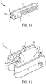
- FIG. 14 shows an embodiment in which a connecting portion 2 is located along a long side of heat transfer plates 1 that have an elongated rectangular shape. While this embodiment locates the connecting portion 2 at one end of the plates 1, the connecting portion 2 can be located in any suitable place, and may extend along the entire length of the heat transfer plates 1.
- heat transfer plates 1 in embodiments herein are not limited to rectangular shapes as shown, but instead may have a circular, oval, square, triangular, irregular or other shape.
- This embodiment of FIG. 14 also includes an inlet 3 and outlet 4 that are located at an end of a heat transfer plate 1 and are arranged to introduce or receive heat transfer fluid into or from the heat transfer conduit 5 in a direction generally in a plane of, or along a length of, the adjacent heat transfer plate 1.
- the heat transfer conduit 5 is arranged to cause heat transfer fluid to flow initially along a length of a first heat transfer plate 1a, reverse direction at an end opposite the inlet 3 and flow back along a length of the first heat transfer plate 1a to the connecting portion 2.
- the fluid may flow from the connecting portion 2 along a length of the second heat transfer plate 1b, reverse direction at an end of the plate 1 opposite the outlet 4, and then flow along a length of the second heat transfer plate 1b to the outlet 4.
- other flow arrangements are possible.
- FIG. 15 shows yet another embodiment that includes three pairs of opposed or otherwise facing heat transfer plates 1a,1b and 1c,1d and 1e,1f.
- first and third connecting portions 2 are arranged at the short side of two pairs of heat transfer plates 1a, 1b and 1e,1f, and a second connecting portion 2 is arranged at the long side of a pair of heat transfer plates 1c,1d. While the heat transfer plates 1 are arranged in generally parallel planes, the first and third connecting portions 2 have bends with radii that extend in a horizontal plane and the second connecting portion 2 has a bend with radii that extend in a vertical plane.
- inlet and outlet ports 3,4 may be arranged in any suitable way, and in this embodiment an inlet 3 is adjacent a first heat transfer plate 1a and an outlet 4 is adjacent a sixth heat transfer plate If.
- the heat transfer conduit 5 is arranged to conduct flow of heat transfer fluid from the inlet 3 and so the fluid flows past the first heat transfer plate 1a, to the first connecting portion 2, then to the second and third heat transfer plates 1b, 1c, then to the second connecting portion 2, then to the fourth and fifth heat transfer plates 1d,1e, then to the third connecting portion 2, and to the sixth heat transfer plate If and the outlet 4.
- the assembly 10 may be constructed in any suitable way, e.g., a first metal sheet may be formed to define the first, second, fifth and sixth heat transfer plates 1 as well as part of the connecting portions 2, and a second metal sheet may be formed to define the third and fourth heat transfer plates 1 as well as part of the connecting portions 2 and the inlet 3 and outlet 4.
- These two metal sheets may be joined together to define the heat transfer conduit 5 that extends from the inlet 3 to the outlet 4, e.g., a gap may be defined between the two metal sheets to define a passageway for the heat transfer conduit 5.
- the metal sheets Before or after being joined together, the metal sheets may be bent to form the shape shown in FIG. 15 . While the connecting portions 2 in this embodiment have bends that extend along 180 degrees, other arc extensions are possible, such as 90 degrees or less.
- FIGs. 16 and 17 show a heat exchanger assembly 10 that has a connecting portion 2 having a bend that supports heat transfer plates 1a, 1b so the heat transfer surfaces are arranged at an angle of about 180 degrees relative to each other.
- the heat transfer plates 1a, 1b are secured to a channel member 6 that defines the connecting portion 2, inlet 3, outlet 4 and heat transfer conduit 5.
- the channel member 6 is arranged with a pair of openings into which the heat transfer plates 1a, 1b are received.
- the heat transfer plates 1a, 1b may be metallic elements, e.g., metal sheet portions, that are adhered, welded, or otherwise secured to the channel member 6 at the openings.
- the heat transfer plates 1a, 1b may be co-molded with a channel member 6, e.g., by placing metal sheet portions in a mold or other form in which polymer material is injected or otherwise introduced to form the channel member 6 and secure the channel member 6 to the plates 1a, 1b.
- Other arrangements are possible though, such as forming the channel member 6 separately from the plates 1a, 1b, and then securing the plates 1a, 1b to the channel member 6 at the corresponding openings.
- the plates 1a, 1b may be sealingly secured to the channel member 6 to help prevent heat transfer fluid in the heat transfer conduit 5 from leaking.
- the channel member 6 may be formed in a way similar to that in FIGs. 2-3 (e.g., of a formed metal sheet or molded polymer material), and the heat transfer plates 1a, 1b may be formed from a single metal sheet that is secured to the channel member 6.
- the connecting portion 2 includes a bend that extends along an arc of about 30 to 90 degrees, although other bend arcs are possible, e.g., up to and including bend arcs of 270 degrees.
- an arc along which a bend of the connecting portion 2 extends need not correspond to an angle at which the heat transfer surfaces are arranged with respect to each other.
- the connecting portion in FIG. 1 has a bend that extends along an arc of about 180 degrees while the heat transfer surfaces are arranged at a 0 degree angle relative to each other.
- the bend could extend along other arc lengths, such as 200 degrees or more.
- the connecting portion 2 may provide elastic and/or plastic support to the plates 1a, 1b, i.e., a part of the connecting portion 2 may allow for the plates 1a, 1b to be moved relative to each other with corresponding elastic and/or plastic deformation of a part of the connecting portion 2.
Landscapes
- Engineering & Computer Science (AREA)
- Physics & Mathematics (AREA)
- Thermal Sciences (AREA)
- Mechanical Engineering (AREA)
- General Engineering & Computer Science (AREA)
- Heat-Exchange Devices With Radiators And Conduit Assemblies (AREA)
Claims (15)
- Montage (10) zum Übertragen von Wärme in Bezug auf ein Bauteil (20), die umfasst:eine erste Wärmeübertragungsplatte (1a), die eine erste Wärmeübertragungsoberfläche aufweist, die eingerichtet ist, um eine erste Bauteiloberfläche zu berühren und Wärme zu ihr zu übertragen;eine zweite Wärmeübertragungsplatte (1b), die eine zweite Wärmeübertragungsoberfläche aufweist, die eingerichtet ist, um eine zweite Bauteiloberfläche zu berühren und Wärme zu ihr zu übertragen, und die in einem Winkel von 270 Grad oder weniger zu der ersten Wärmeübertragungsoberfläche eingerichtet ist;einen Verbindungsabschnitt (2), der sich zwischen der ersten und der zweiten Wärmeübertragungsplatte erstreckt und sie miteinander verbindet, wobei der Verbindungsabschnitt eine Biegung beinhaltet, die sich entlang eines Bogens von mindestens 30 Grad erstreckt;eine Wärmeübertragungsleitung (5), die eingerichtet ist, um einen Fluss von Wärmeübertragungsfluid zu der ersten und der zweiten Wärmeübertragungsplatte zu leiten, wobei die Wärmeübertragungsleitung mindestens eine Passage beinhaltet, die sich von der ersten Wärmeübertragungsplatte zu dem Verbindungsabschnitt und von dem Verbindungsabschnitt zu der zweiten Wärmeübertragungsplatte erstreckt;wobei die Wärmeübertragungsleitung eine Querschnittfläche in einem Teil des Verbindungsabschnitts aufweist, die von einer Querschnittfläche nahe der ersten und der zweiten Wärmeübertragungsplatte unterschiedlich ist; undeinen Einlass- und einen Auslassanschluss (3, 4), die jeweils eingerichtet sind, um Wärmeübertragungsfluid in die Wärmeübertragungsleitung und aus der Wärmeübertragungsleitung heraus zu leiten,dadurch gekennzeichnet, dass die Wärmeübertragungsleitung (5) eine Querschnittfläche in einem Teil des Verbindungsabschnitts (2) aufweist, die entweder kleiner oder größer ist als eine Querschnittfläche an der ersten und der zweiten Wärmeübertragungsplatte (1a, 1b).
- Montage (10) nach Anspruch 1, wobei der Verbindungsabschnitt eingerichtet ist, um nachgiebiges Stützen der ersten und der zweiten Wärmeübertragungsplatte bereitzustellen, das es der ersten und der zweiten Wärmeübertragungsoberfläche erlaubt, zueinander und voneinander weg bewegbar zu sein.
- Montage (10) nach Anspruch 1 oder 2, wobei die erste und die zweite Wärmeübertragungsplatte (1a, 1b) und mindestens ein Teil des Verbindungsabschnitts (2) als ein einziges einheitliches Teil (9) gebildet sind, wobei das einzige einheitliche Teil vorzugsweise eine Metallplatte ist, die gebildet ist, um die erste und die zweite Wärmeübertragungsplatte (1a, 1b) und mindestens einen Teil des Verbindungsabschnitts (2) zu definieren.
- Montage (10) nach Anspruch 3, die weiter ein Kanalelement (6) umfasst, das mindestens teilweise die Wärmeübertragungsleitung (5) und mindestens einen Teil des Verbindungsabschnitts (2) definiert, wobei das Kanalelement an dem einzelnen einheitlichen Teil (9) gesichert sind.
- Montage (10) nach Anspruch 4, die weiter Beabstandungselemente zwischen dem Kanalelement (6) und dem einzelnen einheitlichen Teil (9) in dem Verbindungsabschnitt (2) umfassen, um ein Maß der Wärmeübertragungsleitung (5) zu definieren.
- Montage (10) nach Anspruch 5, wobei:das Kanalelement (6) und das einzige einheitliche Teil (9) jeweils einen Umfang aufweisen, wobei die Umfänge des Kanalelements und des einzelnen einheitlichen Teils abdichtend aneinander gefügt sind; und/oderdas Kanalelement aus einem Plattenmaterial gebildet ist, das gebogen ist, um eine konvexe Sektion zu definieren, die einen Teil der Wärmeübertragungsleitung definiert.
- Montage (10) nach einem der vorstehenden Ansprüche, wobei
der Einlassanschluss (3) an die erste Wärmeübertragungsplatte (1a) angrenzend liegt, und der Auslassanschluss (4) an die zweite Wärmeübertragungsplatte (1b) angrenzend liegt; und/oder
die Montage weiter ein Kanalelement (6) umfasst, das mindestens einen Abschnitt der Wärmeübertragungsleitung (5) und den Einlass- und den Auslassanschluss definiert, wobei sich das Kanalelement von der ersten Wärmeübertragungsplatte zu der zweiten Wärmeübertragungsplatte entlang des Verbindungsabschnitts (2) erstreckt, wobei das Kanalelement optional abdichtend in den Verbindungsabschnitt derart eingreift, dass das Kanalelement und der Verbindungsabschnitt gemeinsam mindestens einen Abschnitt der Wärmeübertragungsleitung definieren. - Montage (10) nach einem der vorstehenden Ansprüche, wobei
die Wärmeübertragungsleitung (5) und der Einlass- und der Auslassanschluss (3, 4) derart eingerichtet sind, dass Wärmeübertragungsfluid von der ersten Wärmeübertragungsplatte (1a) zu der zweiten Wärmeübertragungsplatte (1b) und zurück zu der ersten Wärmeübertragungsplatte fließt, bevor es die Wärmeübertragungsleitung über den Auslassanschluss verlässt; und/oder
die erste und die zweite Wärmeübertragungsplatte jeweils eine Seite jeweils der ersten und der zweiten Wärmeübertragungsoberfläche entgegengesetzt aufweisen, die für Berührung mit dem Wärmeübertragungsfluid in der Wärmeübertragungsleitung exponiert sind. - Montage (10) nach einem der vorstehenden Ansprüche, die weiter mindestens eine Befestigung (8) umfasst, die die erste und die zweite Wärmeübertragungsplatte (1a, 1b) drückt, um sich zueinander zu bewegen, um ein Bauteil (20) zwischen der ersten und der zweiten Wärmeübertragungsplatte zu sichern, wobei die mindestens eine Befestigung optional integral mit der ersten Wärmeübertragungsplatte gebildet ist.
- Montage (10) nach einem der vorstehenden Ansprüche, wobei der Verbindungsabschnitt (2) eine Biegung beinhaltet, die sich entlang eines Bogens von mindestens 90 Grad erstreckt.
- Montage (10) nach einem der vorstehenden Ansprüche, wobei
die erste und die zweite Wärmeübertragungsoberfläche flach sind; und/oder
die Wärmeübertragungsoberflächen durch metallische Elemente definiert sind, und der Verbindungsabschnitt (2) und die Wärmeübertragungsleitung (5) mindestens zum Teil aus einem Polymerelement gebildet sind, wobei die metallischen Elemente vorzugsweise gemeinsam mit dem Polymerelement geformt oder daran geklebt sind; und/oder
die Wärmeübertragungsplatten (1a, 1b) jeweils aus einem metallischen Element gebildet sind, und die Wärmeübertragungsplatten mit einem Polymerelement geformt sind, das mindestens zum Teil den Verbindungsabschnitt, den Einlassanschluss (3), den Auslassanschluss (4) und/oder die Wärmeübertragungsleitung definiert. - Verfahren zum Bilden einer Montage (10) zum Übertragen von Wärme in Bezug auf ein Bauteil (20), das umfasst:Bereitstellen einer ersten und einer zweiten Wärmeübertragungsplatte (1a, 1b), die jeweils eine erste und eine zweite Oberfläche aufweisen, die eingerichtet sind, um die erste und die zweite Bauteiloberfläche zu berühren und Wärme zu ihnen zu übertragen, wobei die erste und die zweite Wärmeübertragungsplatte durch einen Verbindungsabschnitt (2) verbunden sind, der sich zwischen der ersten und der zweiten Wärmeübertragungsplatte erstreckt;Biegen des Verbindungsabschnitts (2) derart, dass die zweite Wärmeübertragungsoberfläche der ersten Wärmeübertragungsoberfläche gegenüberliegt und in einem Winkel von mindestens 30 Grad zu der ersten Wärmeübertragungsoberfläche eingerichtet ist, wobei der gebogene Verbindungsabschnitt nachgiebiges Stützen der ersten und der zweiten Wärmeübertragungsplatte bereitstellt, das es der ersten und der zweiten Wärmeübertragungsoberfläche erlaubt, zueinander und voneinander weg bewegbar zu sein; undBereitstellen einer Wärmeübertragungsleitung (5), die eingerichtet ist, um einen Fluss von Wärmeübertragungsfluid zu der ersten und der zweiten Wärmeübertragungsplatte zu leiten, wobei die Wärmeübertragungsleitung mindestens eine Passage beinhaltet, die sich von der ersten Wärmeübertragungsplatte zu dem Verbindungsabschnitt und von dem Verbindungsabschnitt zu der zweiten Wärmeübertragungsplatte erstreckt,dadurch gekennzeichnet, dass die Wärmeübertragungsleitung eine Querschnittfläche in einem Teil des Verbindungsabschnitts aufweist, die entweder kleiner oder größer ist als eine Querschnittfläche an der ersten und der zweiten Wärmeübertragungsplatte.
- Verfahren nach Anspruch 12, das weiter umfasst:
Bereitstellen von Einlass- und eines Auslassanschlüssen (3, 4), die jeweils eingerichtet sind, um Wärmeübertragungsfluid in die Wärmeübertragungsleitung (5) und aus der Wärmeübertragungsleitung heraus zu leiten. - Verfahren nach Anspruch 12 oder 13, wobei
der Schritt des Bereitstellens der Wärmeübertragungsleitung (5) das Sichern eines Kanalelement (6) an dem Verbindungsabschnitt (2) derart umfasst, dass das Kanalelement und der Verbindungsabschnitt gemeinsam mindestens zum Teil die Wärmeübertragungsleitung definieren, wobei Beabstandungselemente zwischen dem Kanalelement (6) und dem einzelnen einheitlichen Teil (9) in dem Verbindungsabschnitt (2) bereitgestellt sind, um ein Maß der Wärmeübertragungsleitung (5) zu definieren; und/oder
der Schritt des Sicherns des Kanalelements an dem Verbindungsabschnitt vor dem Schritt des Biegens des Verbindungsabschnitts ausgeführt wird, und der Schritt des Biegens des Verbindungsabschnitts das Biegen des Kanalelements beinhaltet; und/oder
der Schritt des Biegens des Verbindungsabschnitts das Biegen eines Teils des Verbindungsabschnitts beinhaltet, um eine Biegung zu bilden, die sich entlang von mindestens 90 Grad erstreckt. - Verfahren nach einem der Ansprüche 12 bis 14, wobei der Schritt des Bereitstellens der ersten und der zweiten Wärmeübertragungsplatte (1a, 1b) das Bereitstellen eines einzigen einheitlichen Teils beinhaltet, das die erste und die zweite Wärmeübertragungsplatte und den Verbindungsabschnitt (2) definiert, wobei das Kanalelement (6) optional einen konvexen Abschnitt aufweist, der mindestens zum Teil die Wärmeübertragungsleitung (5) und eine Umfangskante definiert, und der Schritt des Sicherns des Kanalelements an dem Verbindungsabschnitt das abdichtende Sichern der Umfangskante des Kanalelements an dem einzigen einheitlichen Teil derart beinhaltet, dass das Kanalelement und das einzige einheitliche Teil gemeinsam die Wärmeübertragungsleitung definieren.
Applications Claiming Priority (1)
| Application Number | Priority Date | Filing Date | Title |
|---|---|---|---|
| US15/943,931 US20190301809A1 (en) | 2018-04-03 | 2018-04-03 | Wrap around heat exchanger |
Publications (2)
| Publication Number | Publication Date |
|---|---|
| EP3550246A1 EP3550246A1 (de) | 2019-10-09 |
| EP3550246B1 true EP3550246B1 (de) | 2020-12-09 |
Family
ID=66091920
Family Applications (1)
| Application Number | Title | Priority Date | Filing Date |
|---|---|---|---|
| EP19166756.7A Active EP3550246B1 (de) | 2018-04-03 | 2019-04-02 | Rundumwärmetauscher |
Country Status (3)
| Country | Link |
|---|---|
| US (1) | US20190301809A1 (de) |
| EP (1) | EP3550246B1 (de) |
| CN (1) | CN110345793A (de) |
Families Citing this family (6)
| Publication number | Priority date | Publication date | Assignee | Title |
|---|---|---|---|---|
| DE102018127017A1 (de) * | 2018-10-30 | 2020-04-30 | Hanon Systems | Vorrichtung zur Wärmeübertragung zum Temperieren von Batterien und Bauteilen der Leistungselektronik |
| DE102018128102A1 (de) * | 2018-11-09 | 2020-05-14 | Lauda Dr. R. Wobser Gmbh & Co. Kg. | Vorrichtung zur extrakorporalen Temperierung von Patienten mit einem trennbaren Sekundärkörper |
| CN111417272B (zh) * | 2020-03-19 | 2021-05-11 | 东莞市东准电子科技有限公司 | 一种铝塑复合直接传热的电源盒 |
| JP7497640B2 (ja) * | 2020-07-28 | 2024-06-11 | 株式会社レゾナック | 熱交換器およびその製造方法 |
| DE102021112417A1 (de) * | 2021-05-12 | 2022-11-17 | Erwin Quarder Systemtechnik Gmbh | Anordnung aus Kühleinrichtung und Kühlgegenstand |
| DE102021112415A1 (de) * | 2021-05-12 | 2022-11-17 | Erwin Quarder Systemtechnik Gmbh | Kühleinrichtung zum Abführen von Wärme |
Family Cites Families (18)
| Publication number | Priority date | Publication date | Assignee | Title |
|---|---|---|---|---|
| WO1999019908A1 (en) * | 1997-10-14 | 1999-04-22 | Matsushita Electric Industrial Co., Ltd. | Thermal conductive unit and thermal connection structure using same |
| EP2234154B1 (de) * | 2000-04-19 | 2016-03-30 | Denso Corporation | Kühlmittelgekühlte Halbleiteranordnung |
| US6349035B1 (en) * | 2000-09-29 | 2002-02-19 | Compaq Information Technologies Group, L.P. | Method and apparatus for tooless mating of liquid cooled cold plate with tapered interposer heat sink |
| EP1249868A1 (de) * | 2001-04-12 | 2002-10-16 | ABB Schweiz AG | Kühlungseinrichtung für ein elektronisches Bauelement sowie Kühlsystem mit solchen Kühlungseinrichtungen |
| ITBO20010258A1 (it) | 2001-04-27 | 2002-10-27 | Aavid Thermalloy S R L | Dissipatore di calore a fluido per componenti elettronici |
| US6882536B2 (en) * | 2002-04-25 | 2005-04-19 | Hewlett-Packard Development Company, L.P. | Wrap-around cooling arrangement for printed circuit board |
| JP2004037039A (ja) * | 2002-07-05 | 2004-02-05 | Sony Corp | 冷却装置、電子機器装置、表示装置及び冷却装置の製造方法 |
| US7167366B2 (en) * | 2002-09-11 | 2007-01-23 | Kioan Cheon | Soft cooling jacket for electronic device |
| US20050061473A1 (en) * | 2003-09-22 | 2005-03-24 | Coolhead Technologies, Inc. | Flexible heat exchangers |
| EP1921676B1 (de) | 2006-11-13 | 2019-03-06 | Aavid Thermalloy S.r.l. | Kühlkörper |
| US7965508B2 (en) * | 2007-03-27 | 2011-06-21 | Denso Corporation | Cooling device for electronic component and power converter equipped with the same |
| JP4978448B2 (ja) * | 2007-12-07 | 2012-07-18 | 株式会社デンソー | 積層型冷却器 |
| DE112010002307T5 (de) * | 2009-06-22 | 2012-06-21 | Meidensha Corp. | Kühlkörper |
| CN102544567B (zh) * | 2010-12-30 | 2014-10-29 | 上海航天电源技术有限责任公司 | 带有液冷系统的动力电池模块 |
| US9578788B2 (en) * | 2013-03-15 | 2017-02-21 | Atieva, Inc. | Inverter power module packaging with cold plate |
| JP2014225348A (ja) * | 2013-05-15 | 2014-12-04 | 三菱重工オートモーティブサーマルシステムズ株式会社 | 熱媒体加熱装置およびその製造方法並びにそれを用いた車両用空調装置 |
| DE112014004189T5 (de) * | 2013-09-12 | 2016-06-02 | Hanon Systems | Wärmetauscher zum Kühlen eines elektrischen Bauteils |
| TWI489674B (zh) * | 2014-01-13 | 2015-06-21 | 新普科技股份有限公司 | 散熱件及其組成之電池模組 |
-
2018
- 2018-04-03 US US15/943,931 patent/US20190301809A1/en not_active Abandoned
- 2018-06-06 CN CN201810575524.1A patent/CN110345793A/zh active Pending
-
2019
- 2019-04-02 EP EP19166756.7A patent/EP3550246B1/de active Active
Non-Patent Citations (1)
| Title |
|---|
| None * |
Also Published As
| Publication number | Publication date |
|---|---|
| CN110345793A (zh) | 2019-10-18 |
| EP3550246A1 (de) | 2019-10-09 |
| US20190301809A1 (en) | 2019-10-03 |
Similar Documents
| Publication | Publication Date | Title |
|---|---|---|
| EP3550246B1 (de) | Rundumwärmetauscher | |
| US8451609B2 (en) | Cooling device for a plurality of power modules | |
| CN114342155B (zh) | 高性能均匀温度的冷板 | |
| US11056735B2 (en) | Heat exchanger and battery unit structure for cooling thermally conductive batteries | |
| EP2834841B1 (de) | Halbleiterkühlvorrichtung | |
| EP2962355B1 (de) | Kühlelement für batterien | |
| JP5445507B2 (ja) | 電力変換装置 | |
| KR102351954B1 (ko) | 전기소자 냉각용 열교환기 | |
| EP4323713A1 (de) | Flüssigkeitsgekühlte kühlplatte | |
| WO2017031596A1 (en) | Heat exchanger with plate-like conduits for cooling electronic components | |
| US8707715B2 (en) | Thermoelectric conversion unit | |
| KR101781923B1 (ko) | 배터리 냉각장치 | |
| US9553038B2 (en) | Semiconductor cooling apparatus | |
| US20120234021A1 (en) | Heat exchanger | |
| CN215379665U (zh) | 一种螺旋型复合鳍片散热器结构及散热器 | |
| CN207602552U (zh) | 用于双面冷却至少一个发热电子部件的换热器组件 | |
| KR20170056196A (ko) | 전력반도체용 냉각장치 | |
| KR102704167B1 (ko) | 매니폴드 유로 히트싱크 | |
| US20050039880A1 (en) | Computer cooling apparatus | |
| JP2026040457A (ja) | 液冷式ヒートシンク | |
| JP6107400B2 (ja) | 電力変換装置 | |
| TW202612417A (zh) | 液冷式散熱器 | |
| JP2026022930A (ja) | 熱輸送装置及び熱輸送装置の製造方法 | |
| KR20260010124A (ko) | 회로 카드 냉각 시스템 | |
| JP2025540546A (ja) | 放熱装置、放熱システムと光モジュール放熱機器 |
Legal Events
| Date | Code | Title | Description |
|---|---|---|---|
| PUAI | Public reference made under article 153(3) epc to a published international application that has entered the european phase |
Free format text: ORIGINAL CODE: 0009012 |
|
| STAA | Information on the status of an ep patent application or granted ep patent |
Free format text: STATUS: THE APPLICATION HAS BEEN PUBLISHED |
|
| AK | Designated contracting states |
Kind code of ref document: A1 Designated state(s): AL AT BE BG CH CY CZ DE DK EE ES FI FR GB GR HR HU IE IS IT LI LT LU LV MC MK MT NL NO PL PT RO RS SE SI SK SM TR |
|
| AX | Request for extension of the european patent |
Extension state: BA ME |
|
| STAA | Information on the status of an ep patent application or granted ep patent |
Free format text: STATUS: REQUEST FOR EXAMINATION WAS MADE |
|
| 17P | Request for examination filed |
Effective date: 20200409 |
|
| RBV | Designated contracting states (corrected) |
Designated state(s): AL AT BE BG CH CY CZ DE DK EE ES FI FR GB GR HR HU IE IS IT LI LT LU LV MC MK MT NL NO PL PT RO RS SE SI SK SM TR |
|
| RIC1 | Information provided on ipc code assigned before grant |
Ipc: F28D 1/047 20060101ALI20200518BHEP Ipc: H05K 7/20 20060101ALI20200518BHEP Ipc: H01L 23/473 20060101ALI20200518BHEP Ipc: F28D 1/03 20060101AFI20200518BHEP |
|
| GRAP | Despatch of communication of intention to grant a patent |
Free format text: ORIGINAL CODE: EPIDOSNIGR1 |
|
| STAA | Information on the status of an ep patent application or granted ep patent |
Free format text: STATUS: GRANT OF PATENT IS INTENDED |
|
| INTG | Intention to grant announced |
Effective date: 20200713 |
|
| GRAS | Grant fee paid |
Free format text: ORIGINAL CODE: EPIDOSNIGR3 |
|
| GRAA | (expected) grant |
Free format text: ORIGINAL CODE: 0009210 |
|
| STAA | Information on the status of an ep patent application or granted ep patent |
Free format text: STATUS: THE PATENT HAS BEEN GRANTED |
|
| AK | Designated contracting states |
Kind code of ref document: B1 Designated state(s): AL AT BE BG CH CY CZ DE DK EE ES FI FR GB GR HR HU IE IS IT LI LT LU LV MC MK MT NL NO PL PT RO RS SE SI SK SM TR |
|
| REG | Reference to a national code |
Ref country code: GB Ref legal event code: FG4D |
|
| REG | Reference to a national code |
Ref country code: CH Ref legal event code: EP Ref country code: AT Ref legal event code: REF Ref document number: 1343873 Country of ref document: AT Kind code of ref document: T Effective date: 20201215 |
|
| REG | Reference to a national code |
Ref country code: DE Ref legal event code: R096 Ref document number: 602019001627 Country of ref document: DE |
|
| REG | Reference to a national code |
Ref country code: IE Ref legal event code: FG4D |
|
| PG25 | Lapsed in a contracting state [announced via postgrant information from national office to epo] |
Ref country code: GR Free format text: LAPSE BECAUSE OF FAILURE TO SUBMIT A TRANSLATION OF THE DESCRIPTION OR TO PAY THE FEE WITHIN THE PRESCRIBED TIME-LIMIT Effective date: 20210310 Ref country code: NO Free format text: LAPSE BECAUSE OF FAILURE TO SUBMIT A TRANSLATION OF THE DESCRIPTION OR TO PAY THE FEE WITHIN THE PRESCRIBED TIME-LIMIT Effective date: 20210309 Ref country code: RS Free format text: LAPSE BECAUSE OF FAILURE TO SUBMIT A TRANSLATION OF THE DESCRIPTION OR TO PAY THE FEE WITHIN THE PRESCRIBED TIME-LIMIT Effective date: 20201209 Ref country code: FI Free format text: LAPSE BECAUSE OF FAILURE TO SUBMIT A TRANSLATION OF THE DESCRIPTION OR TO PAY THE FEE WITHIN THE PRESCRIBED TIME-LIMIT Effective date: 20201209 |
|
| REG | Reference to a national code |
Ref country code: AT Ref legal event code: MK05 Ref document number: 1343873 Country of ref document: AT Kind code of ref document: T Effective date: 20201209 |
|
| PG25 | Lapsed in a contracting state [announced via postgrant information from national office to epo] |
Ref country code: BG Free format text: LAPSE BECAUSE OF FAILURE TO SUBMIT A TRANSLATION OF THE DESCRIPTION OR TO PAY THE FEE WITHIN THE PRESCRIBED TIME-LIMIT Effective date: 20210309 Ref country code: SE Free format text: LAPSE BECAUSE OF FAILURE TO SUBMIT A TRANSLATION OF THE DESCRIPTION OR TO PAY THE FEE WITHIN THE PRESCRIBED TIME-LIMIT Effective date: 20201209 Ref country code: LV Free format text: LAPSE BECAUSE OF FAILURE TO SUBMIT A TRANSLATION OF THE DESCRIPTION OR TO PAY THE FEE WITHIN THE PRESCRIBED TIME-LIMIT Effective date: 20201209 |
|
| REG | Reference to a national code |
Ref country code: NL Ref legal event code: MP Effective date: 20201209 |
|
| PG25 | Lapsed in a contracting state [announced via postgrant information from national office to epo] |
Ref country code: HR Free format text: LAPSE BECAUSE OF FAILURE TO SUBMIT A TRANSLATION OF THE DESCRIPTION OR TO PAY THE FEE WITHIN THE PRESCRIBED TIME-LIMIT Effective date: 20201209 Ref country code: NL Free format text: LAPSE BECAUSE OF FAILURE TO SUBMIT A TRANSLATION OF THE DESCRIPTION OR TO PAY THE FEE WITHIN THE PRESCRIBED TIME-LIMIT Effective date: 20201209 |
|
| REG | Reference to a national code |
Ref country code: LT Ref legal event code: MG9D |
|
| PG25 | Lapsed in a contracting state [announced via postgrant information from national office to epo] |
Ref country code: CZ Free format text: LAPSE BECAUSE OF FAILURE TO SUBMIT A TRANSLATION OF THE DESCRIPTION OR TO PAY THE FEE WITHIN THE PRESCRIBED TIME-LIMIT Effective date: 20201209 Ref country code: EE Free format text: LAPSE BECAUSE OF FAILURE TO SUBMIT A TRANSLATION OF THE DESCRIPTION OR TO PAY THE FEE WITHIN THE PRESCRIBED TIME-LIMIT Effective date: 20201209 Ref country code: SK Free format text: LAPSE BECAUSE OF FAILURE TO SUBMIT A TRANSLATION OF THE DESCRIPTION OR TO PAY THE FEE WITHIN THE PRESCRIBED TIME-LIMIT Effective date: 20201209 Ref country code: SM Free format text: LAPSE BECAUSE OF FAILURE TO SUBMIT A TRANSLATION OF THE DESCRIPTION OR TO PAY THE FEE WITHIN THE PRESCRIBED TIME-LIMIT Effective date: 20201209 Ref country code: PT Free format text: LAPSE BECAUSE OF FAILURE TO SUBMIT A TRANSLATION OF THE DESCRIPTION OR TO PAY THE FEE WITHIN THE PRESCRIBED TIME-LIMIT Effective date: 20210409 Ref country code: RO Free format text: LAPSE BECAUSE OF FAILURE TO SUBMIT A TRANSLATION OF THE DESCRIPTION OR TO PAY THE FEE WITHIN THE PRESCRIBED TIME-LIMIT Effective date: 20201209 Ref country code: LT Free format text: LAPSE BECAUSE OF FAILURE TO SUBMIT A TRANSLATION OF THE DESCRIPTION OR TO PAY THE FEE WITHIN THE PRESCRIBED TIME-LIMIT Effective date: 20201209 |
|
| PG25 | Lapsed in a contracting state [announced via postgrant information from national office to epo] |
Ref country code: AT Free format text: LAPSE BECAUSE OF FAILURE TO SUBMIT A TRANSLATION OF THE DESCRIPTION OR TO PAY THE FEE WITHIN THE PRESCRIBED TIME-LIMIT Effective date: 20201209 Ref country code: PL Free format text: LAPSE BECAUSE OF FAILURE TO SUBMIT A TRANSLATION OF THE DESCRIPTION OR TO PAY THE FEE WITHIN THE PRESCRIBED TIME-LIMIT Effective date: 20201209 |
|
| REG | Reference to a national code |
Ref country code: DE Ref legal event code: R097 Ref document number: 602019001627 Country of ref document: DE |
|
| PG25 | Lapsed in a contracting state [announced via postgrant information from national office to epo] |
Ref country code: IS Free format text: LAPSE BECAUSE OF FAILURE TO SUBMIT A TRANSLATION OF THE DESCRIPTION OR TO PAY THE FEE WITHIN THE PRESCRIBED TIME-LIMIT Effective date: 20210409 |
|
| PLBE | No opposition filed within time limit |
Free format text: ORIGINAL CODE: 0009261 |
|
| STAA | Information on the status of an ep patent application or granted ep patent |
Free format text: STATUS: NO OPPOSITION FILED WITHIN TIME LIMIT |
|
| PG25 | Lapsed in a contracting state [announced via postgrant information from national office to epo] |
Ref country code: AL Free format text: LAPSE BECAUSE OF FAILURE TO SUBMIT A TRANSLATION OF THE DESCRIPTION OR TO PAY THE FEE WITHIN THE PRESCRIBED TIME-LIMIT Effective date: 20201209 Ref country code: IT Free format text: LAPSE BECAUSE OF FAILURE TO SUBMIT A TRANSLATION OF THE DESCRIPTION OR TO PAY THE FEE WITHIN THE PRESCRIBED TIME-LIMIT Effective date: 20201209 |
|
| 26N | No opposition filed |
Effective date: 20210910 |
|
| PG25 | Lapsed in a contracting state [announced via postgrant information from national office to epo] |
Ref country code: DK Free format text: LAPSE BECAUSE OF FAILURE TO SUBMIT A TRANSLATION OF THE DESCRIPTION OR TO PAY THE FEE WITHIN THE PRESCRIBED TIME-LIMIT Effective date: 20201209 Ref country code: SI Free format text: LAPSE BECAUSE OF FAILURE TO SUBMIT A TRANSLATION OF THE DESCRIPTION OR TO PAY THE FEE WITHIN THE PRESCRIBED TIME-LIMIT Effective date: 20201209 Ref country code: MC Free format text: LAPSE BECAUSE OF FAILURE TO SUBMIT A TRANSLATION OF THE DESCRIPTION OR TO PAY THE FEE WITHIN THE PRESCRIBED TIME-LIMIT Effective date: 20201209 |
|
| PG25 | Lapsed in a contracting state [announced via postgrant information from national office to epo] |
Ref country code: LU Free format text: LAPSE BECAUSE OF NON-PAYMENT OF DUE FEES Effective date: 20210402 |
|
| REG | Reference to a national code |
Ref country code: BE Ref legal event code: MM Effective date: 20210430 |
|
| PG25 | Lapsed in a contracting state [announced via postgrant information from national office to epo] |
Ref country code: FR Free format text: LAPSE BECAUSE OF NON-PAYMENT OF DUE FEES Effective date: 20210430 Ref country code: ES Free format text: LAPSE BECAUSE OF FAILURE TO SUBMIT A TRANSLATION OF THE DESCRIPTION OR TO PAY THE FEE WITHIN THE PRESCRIBED TIME-LIMIT Effective date: 20201209 |
|
| PG25 | Lapsed in a contracting state [announced via postgrant information from national office to epo] |
Ref country code: IE Free format text: LAPSE BECAUSE OF NON-PAYMENT OF DUE FEES Effective date: 20210402 |
|
| PG25 | Lapsed in a contracting state [announced via postgrant information from national office to epo] |
Ref country code: IS Free format text: LAPSE BECAUSE OF FAILURE TO SUBMIT A TRANSLATION OF THE DESCRIPTION OR TO PAY THE FEE WITHIN THE PRESCRIBED TIME-LIMIT Effective date: 20210409 |
|
| PG25 | Lapsed in a contracting state [announced via postgrant information from national office to epo] |
Ref country code: BE Free format text: LAPSE BECAUSE OF NON-PAYMENT OF DUE FEES Effective date: 20210430 |
|
| REG | Reference to a national code |
Ref country code: CH Ref legal event code: PL |
|
| PG25 | Lapsed in a contracting state [announced via postgrant information from national office to epo] |
Ref country code: LI Free format text: LAPSE BECAUSE OF NON-PAYMENT OF DUE FEES Effective date: 20220430 Ref country code: CH Free format text: LAPSE BECAUSE OF NON-PAYMENT OF DUE FEES Effective date: 20220430 |
|
| PG25 | Lapsed in a contracting state [announced via postgrant information from national office to epo] |
Ref country code: CY Free format text: LAPSE BECAUSE OF FAILURE TO SUBMIT A TRANSLATION OF THE DESCRIPTION OR TO PAY THE FEE WITHIN THE PRESCRIBED TIME-LIMIT Effective date: 20201209 |
|
| P01 | Opt-out of the competence of the unified patent court (upc) registered |
Effective date: 20230526 |
|
| PG25 | Lapsed in a contracting state [announced via postgrant information from national office to epo] |
Ref country code: HU Free format text: LAPSE BECAUSE OF FAILURE TO SUBMIT A TRANSLATION OF THE DESCRIPTION OR TO PAY THE FEE WITHIN THE PRESCRIBED TIME-LIMIT; INVALID AB INITIO Effective date: 20190402 |
|
| GBPC | Gb: european patent ceased through non-payment of renewal fee |
Effective date: 20230402 |
|
| PG25 | Lapsed in a contracting state [announced via postgrant information from national office to epo] |
Ref country code: GB Free format text: LAPSE BECAUSE OF NON-PAYMENT OF DUE FEES Effective date: 20230402 |
|
| PG25 | Lapsed in a contracting state [announced via postgrant information from national office to epo] |
Ref country code: GB Free format text: LAPSE BECAUSE OF NON-PAYMENT OF DUE FEES Effective date: 20230402 |
|
| PG25 | Lapsed in a contracting state [announced via postgrant information from national office to epo] |
Ref country code: MK Free format text: LAPSE BECAUSE OF FAILURE TO SUBMIT A TRANSLATION OF THE DESCRIPTION OR TO PAY THE FEE WITHIN THE PRESCRIBED TIME-LIMIT Effective date: 20201209 |
|
| PG25 | Lapsed in a contracting state [announced via postgrant information from national office to epo] |
Ref country code: MT Free format text: LAPSE BECAUSE OF FAILURE TO SUBMIT A TRANSLATION OF THE DESCRIPTION OR TO PAY THE FEE WITHIN THE PRESCRIBED TIME-LIMIT Effective date: 20201209 |
|
| PGFP | Annual fee paid to national office [announced via postgrant information from national office to epo] |
Ref country code: DE Payment date: 20250422 Year of fee payment: 7 |
|
| PG25 | Lapsed in a contracting state [announced via postgrant information from national office to epo] |
Ref country code: TR Free format text: LAPSE BECAUSE OF FAILURE TO SUBMIT A TRANSLATION OF THE DESCRIPTION OR TO PAY THE FEE WITHIN THE PRESCRIBED TIME-LIMIT Effective date: 20201209 |