EP3550525A1 - Dispositif de commande d'affichage, procédé de commande d'affichage et programme - Google Patents
Dispositif de commande d'affichage, procédé de commande d'affichage et programme Download PDFInfo
- Publication number
- EP3550525A1 EP3550525A1 EP17875520.3A EP17875520A EP3550525A1 EP 3550525 A1 EP3550525 A1 EP 3550525A1 EP 17875520 A EP17875520 A EP 17875520A EP 3550525 A1 EP3550525 A1 EP 3550525A1
- Authority
- EP
- European Patent Office
- Prior art keywords
- display control
- target object
- display
- user
- farm animal
- Prior art date
- Legal status (The legal status is an assumption and is not a legal conclusion. Google has not performed a legal analysis and makes no representation as to the accuracy of the status listed.)
- Withdrawn
Links
Images


Classifications
-
- G—PHYSICS
- G09—EDUCATION; CRYPTOGRAPHY; DISPLAY; ADVERTISING; SEALS
- G09G—ARRANGEMENTS OR CIRCUITS FOR CONTROL OF INDICATING DEVICES USING STATIC MEANS TO PRESENT VARIABLE INFORMATION
- G09G5/00—Control arrangements or circuits for visual indicators common to cathode-ray tube indicators and other visual indicators
- G09G5/36—Control arrangements or circuits for visual indicators common to cathode-ray tube indicators and other visual indicators characterised by the display of a graphic pattern, e.g. using an all-points-addressable [APA] memory
- G09G5/37—Details of the operation on graphic patterns
- G09G5/377—Details of the operation on graphic patterns for mixing or overlaying two or more graphic patterns
-
- A—HUMAN NECESSITIES
- A01—AGRICULTURE; FORESTRY; ANIMAL HUSBANDRY; HUNTING; TRAPPING; FISHING
- A01K—ANIMAL HUSBANDRY; AVICULTURE; APICULTURE; PISCICULTURE; FISHING; REARING OR BREEDING ANIMALS, NOT OTHERWISE PROVIDED FOR; NEW BREEDS OF ANIMALS
- A01K11/00—Marking of animals
- A01K11/006—Automatic identification systems for animals, e.g. electronic devices, transponders for animals
-
- A—HUMAN NECESSITIES
- A01—AGRICULTURE; FORESTRY; ANIMAL HUSBANDRY; HUNTING; TRAPPING; FISHING
- A01K—ANIMAL HUSBANDRY; AVICULTURE; APICULTURE; PISCICULTURE; FISHING; REARING OR BREEDING ANIMALS, NOT OTHERWISE PROVIDED FOR; NEW BREEDS OF ANIMALS
- A01K29/00—Other apparatus for animal husbandry
- A01K29/005—Monitoring or measuring activity
-
- G—PHYSICS
- G06—COMPUTING OR CALCULATING; COUNTING
- G06F—ELECTRIC DIGITAL DATA PROCESSING
- G06F3/00—Input arrangements for transferring data to be processed into a form capable of being handled by the computer; Output arrangements for transferring data from processing unit to output unit, e.g. interface arrangements
- G06F3/01—Input arrangements or combined input and output arrangements for interaction between user and computer
-
- G—PHYSICS
- G06—COMPUTING OR CALCULATING; COUNTING
- G06T—IMAGE DATA PROCESSING OR GENERATION, IN GENERAL
- G06T11/00—Two-dimensional [2D] image generation
-
- G—PHYSICS
- G06—COMPUTING OR CALCULATING; COUNTING
- G06T—IMAGE DATA PROCESSING OR GENERATION, IN GENERAL
- G06T19/00—Manipulating three-dimensional [3D] models or images for computer graphics
-
- G—PHYSICS
- G06—COMPUTING OR CALCULATING; COUNTING
- G06T—IMAGE DATA PROCESSING OR GENERATION, IN GENERAL
- G06T19/00—Manipulating three-dimensional [3D] models or images for computer graphics
- G06T19/006—Mixed reality
-
- G—PHYSICS
- G09—EDUCATION; CRYPTOGRAPHY; DISPLAY; ADVERTISING; SEALS
- G09G—ARRANGEMENTS OR CIRCUITS FOR CONTROL OF INDICATING DEVICES USING STATIC MEANS TO PRESENT VARIABLE INFORMATION
- G09G5/00—Control arrangements or circuits for visual indicators common to cathode-ray tube indicators and other visual indicators
- G09G5/36—Control arrangements or circuits for visual indicators common to cathode-ray tube indicators and other visual indicators characterised by the display of a graphic pattern, e.g. using an all-points-addressable [APA] memory
- G09G5/38—Control arrangements or circuits for visual indicators common to cathode-ray tube indicators and other visual indicators characterised by the display of a graphic pattern, e.g. using an all-points-addressable [APA] memory with means for controlling the display position
-
- G—PHYSICS
- G09—EDUCATION; CRYPTOGRAPHY; DISPLAY; ADVERTISING; SEALS
- G09G—ARRANGEMENTS OR CIRCUITS FOR CONTROL OF INDICATING DEVICES USING STATIC MEANS TO PRESENT VARIABLE INFORMATION
- G09G2320/00—Control of display operating conditions
- G09G2320/02—Improving the quality of display appearance
- G09G2320/0261—Improving the quality of display appearance in the context of movement of objects on the screen or movement of the observer relative to the screen
-
- G—PHYSICS
- G09—EDUCATION; CRYPTOGRAPHY; DISPLAY; ADVERTISING; SEALS
- G09G—ARRANGEMENTS OR CIRCUITS FOR CONTROL OF INDICATING DEVICES USING STATIC MEANS TO PRESENT VARIABLE INFORMATION
- G09G2340/00—Aspects of display data processing
- G09G2340/12—Overlay of images, i.e. displayed pixel being the result of switching between the corresponding input pixels
-
- G—PHYSICS
- G09—EDUCATION; CRYPTOGRAPHY; DISPLAY; ADVERTISING; SEALS
- G09G—ARRANGEMENTS OR CIRCUITS FOR CONTROL OF INDICATING DEVICES USING STATIC MEANS TO PRESENT VARIABLE INFORMATION
- G09G2354/00—Aspects of interface with display user
Definitions
- the present disclosure relates to a display control device, a display control method, and a program.
- an augmented reality (AR) technology has become known as a technology for expressing the real world in an augmented state.
- AR augmented reality
- a technique for informing a user that there is one target object in a case in which the one target object located in the field of view of the user is shielded by another object is disclosed (for example, see Patent Literature 1).
- a technique of recognizing one target object located in a field of view of a user and presenting information related to the one target object (hereinafter also referred to as "AR information”) to the user is known.
- Patent Literature 1 JP 2014-106681A
- a display control device including: a display control unit configured to control display of information related to a target object located in a field of view of a user.
- the display control unit controls display of an image related to the target object such that the target object shielded in the field of view is displayed in a form different from a form visually recognized by the user.
- a display control method including: controlling display of information related to a target object located in a field of view of a user; and controlling, by a processor, in a case in which it is determined that at least a part of the target object is shielded by another object on the basis of a position of the user, display of an image related to the target object such that the target object shielded in the field of view is displayed in a form different from a form visually recognized by the user.
- a program causing a computer to function as a display control device including: a display control unit configured to control display of information related to a target object located in a field of view of a user.
- the display control unit controls display of an image related to the target object such that the target object shielded in the field of view is displayed in a form different from a form visually recognized by the user.
- an AR technology has become known as a technology for expressing the real world in an augmented state.
- a technique for informing a user that there is one target object in a case in which the one target object located in the field of view of the user is shielded by another object is disclosed (for example, see JP 2014-106681A ).
- a technique of recognizing one target object located in a field of view of a user and presenting information related to the one target object (AR information) to the user is known.
- the one target object whose AR information is presented to the user (or a plurality of target objects) is a farm animal is mainly assumed.
- the one target object (or a plurality of target objects) whose AR information is presented to the user may not be a farm animal.
- the one target object (or the plurality of target objects) whose AR information is presented to the user may be a living object (such as an athlete as will be described later) or a non-living object (for example, a mobile object such as a vehicle).
- a case in which there is a farm animal in an outdoor farm is mainly assumed, but the farm animal may be in an indoor farm.
- the other object shielding the one target object (or the plurality of target objects) whose AR information is presented to the user may not be a farm animal.
- the other object shielding the one target object (or the plurality of target objects) whose AR information is presented to the user may be an object other than a farm animal (for example, a building, stacked hay, or the like).
- an augmentation expression of the real world is also referred to simply as "AR display.” More specifically, the AR display may refer to display for a position depending on a target object located in the field of view of the user.
- a virtual expression a virtual reality (VR) expression
- VR display a virtual reality (VR) expression
- the VR display may be display for a position not depending on a target object located in the field of view of the user.
- the AR information is not limited to this example.
- FIG. 1 is a diagram illustrating a configuration example of a display control system according to an embodiment of the present disclosure.
- a display control system 1 includes a display control device 10, a server 20, an external sensor 30, wearable devices 40-1 to 40-N, repeaters 50-1 and 50-2, a gateway device 60, and a network 931.
- the network 931 is a wireless local area network (LAN)
- LAN wireless local area network
- the repeater 50 (the repeaters 50-1 and 50-2) relays communication between the wearable device 40 (the wearable devices 40-1 to 40-N) and the server 20.
- the number of repeaters 50 is two, but the number of repeaters 50 is not limited to two and is sufficiently two or more.
- the gateway device 60 connects the network 931 with the repeater 50 (the repeaters 50-1 and 50-2) and the external sensor 30.
- the display control device 10 is a device used by a user U-1.
- a case in which the user U-1 is a farmer breeding a farm animal B will be mainly assumed.
- the user U-1 is not limited to a farmer breeding a farm animal B.
- the user U-1 may be a veterinarian who treats an injury or illness of a farm animal B.
- the display control device 10 in consideration of allowing the user U-1 to efficiently perform manual labor, a case in which the display control device 10 is a type of device that is worn by the user U-1(for example, a glasses type) is assumed. However, the display control device 10 may be a type of device which is not worn by the user U-1 (for example, a smartphone or the like). Further, in this specification, a case in which the display control device 10 is a see-through type device is assumed. However, the display control device 10 may be a non-see-through type device.
- the external sensor 30 is a sensor not directly attached to the body of a corresponding farm animal B (farm animals B-1 to B-N).
- the external sensor 30 is a surveillance camera
- the external sensor 30 is not limited to the surveillance camera.
- the external sensor 30 may be a drone equipped with a camera.
- an image hereinafter also referred to as an "overhead image”
- the direction of the external sensor 30 is not limited.
- the external sensor 30 is a visible light camera.
- a type of external sensor 30 is not limited.
- the external sensor 30 may be an infrared camera or may be any other type of camera such as a depth sensor capable of acquiring three-dimensional data of a space.
- the image obtained by the external sensor 30 is transmitted from the external sensor 30 to the server 20 via the gateway device 60 and the network 931.
- the server 20 is a device that performs various types of information processing for managing the farm animal B (the farm animals B-1 to B-N). Specifically, the server 20 stores information (hereinafter also referred to as "farm animal information") in which identification information, individual information, and position information of the farm animal B (the farm animals B-1 to B-N) are associated with one another.
- the identification information may include individual identification information assigned from a country, an identification number of an Internet of Things (IOT) device, an ID assigned by the user U-1, and the like.
- IOT Internet of Things
- the server 20 updates the farm animal information and reads the farm animal information if necessary. Further, in this specification, a case in which the farm animal information is stored in the server 20 is mainly assumed, but the farm animal information may be stored in a server different from the server 20.
- the wearable device 40 (the wearable devices 40-1 to 40-N) is attached to the body of the corresponding farm animal B (the farm animals B-1 to B-N).
- the wearable device 40 transmits the identification number of the IOT device of the corresponding farm animal B and information specifying the position information to the server 20 via the repeater 50-1, the repeater 50-2, the gateway device 60, and the network 931.
- various types of information are assumed as information specifying the position information of the farm animal B.
- the information specifying the position information of the farm animal B includes a reception strength of a wireless signal transmitted from each of the repeater 50-1 and the repeater 50-2 at predetermined time intervals in the wearable device 40. Then, the server 20 specifies the position information of the wearable device 40 (the farm animal B) on the basis of the reception strengths and the position information of each of the repeaters 50-1 and 50-2. Accordingly, in the server 20, it is possible to manage the position information of the farm animal B in real time.
- the information specifying the position information of the farm animal B is not limited to this example.
- the information specifying the position information of the farm animal B may include an arrival period of time (a difference between a transmission time and a reception time) of a signal received from each Global Positioning System (GPS) satellite by the wearable device 40.
- GPS Global Positioning System
- the position information of the farm animal B may be specified in the wearable device 40. In this case, the position information of the farm animal B may be transmitted to the server 20 instead of the information specifying the position information of the farm animal B.
- the information specifying the position information of the farm animal B may be an overhead image obtained by the external sensor 30.
- the server 20 manages a pattern of the farm animal B in advance for each individual, it is possible for the server 20 to specify a position of the pattern of the farm animal B recognized from the overhead image obtained by the external sensor 30 as the position information of the farm animal B.
- FIG. 2 is a block diagram illustrating a functional configuration example of the display control device 10 according to an embodiment of the present disclosure.
- the display control device 10 includes a control unit 110, a detecting unit 120, a communication unit 130, a storage unit 150, and an output unit 160.
- the functional blocks of the display control device 10 will be described below.
- the control unit 110 controls each unit of the display control device 10. Further, the control unit 110 may be constituted by a processing device such as one or more central processing units (CPUs). In a case in which the control unit 110 is constituted by a processing device such as a CPU, the processing device may be constituted by an electronic circuit. As illustrated in FIG. 2 , the control unit 110 includes a display control unit 111, a selecting unit 112, and a determining unit 113. The blocks of the control unit 110 will be described later in detail.
- the detecting unit 120 is a sensor capable of detecting an indication direction by the user U-1 (hereinafter also referred to simply as an "indication direction") in a three-dimensional space.
- an indication direction for the user U-1
- the line of sight of the user U-1 may be detected using any method.
- the detecting unit 120 includes an imaging device
- the line of sight of the user U-1 may be detected on the basis of an eye region shown in an image obtained by the imaging device.
- the indication direction is not limited to the line of sight of the user U-1.
- the indication direction may be detected on the basis of a detection result by a motion sensor detecting a motion of the user U-1 (an indication direction in which a position in a three-dimensional space detected by a motion sensor is a front may be detected).
- the motion sensor may detect an acceleration with the acceleration sensor or may detect an angular velocity with a gyro sensor (for example, a ring type gyroscope or the like).
- the indication direction may be detected on the basis of a detection result by a tactile device.
- An example of the tactile device is a pen type tactile device.
- the indication direction may be a direction indicated by a predetermined object (for example, a direction in which a leading end of a stick points) or may be a direction indicated by a finger of the user U-1.
- the detecting unit 120 includes an imaging device
- the direction in which the predetermined object points and the direction indicated by the finger of the user U-1 may be detected on the basis of an object and a finger shown in an image obtained by the imaging device.
- the indication direction may be detected on the basis of a face recognition result of the user U-1.
- a center position between the eyes may be recognized on the basis of an image obtained by the imaging device, and a straight line extending from the center position between the eyes may be detected as the indication direction.
- the indication direction may be a direction corresponding to speech content of the user U-1.
- the detecting unit 120 includes a microphone
- the direction corresponding to the speech content of the user U-1 may be detected on the basis of a voice recognition result for sound information obtained by a microphone.
- the user U-1 desires to designate an inner side of the field of view as the front in the indication direction, it is sufficient to produce speech indicating the inner side of the field of view (for example, "speech" such as "the farm animal on the inner side”).
- text data "inner side” is obtained as the voice recognition result for such speech, and the indication direction in which the inner side of the field of view is the front can be detected on the basis of the text data "inner side.”
- the speech content may be "show an overhead image,” “show it from above,” “show the farm animal on the inner side,” or the like.
- the detecting unit 120 can detect various types of manipulations by the user U-1. Further, in this specification, a selection manipulation and a switching manipulation are mainly described as examples of the manipulation by the user U-1. Here, various types of manipulations by the user U-1 may be detected using any method. As an example, various types of manipulations by the user U-1 may be detected on the basis of a motion of the user U-1.
- the detection of the motion of the user U-1 may be performed using any method.
- the motion of the user U-1 may be detected from an image obtained by the imaging device.
- the motion of the user U-1 may be a wink or the like.
- the detecting unit 120 may detect the motion of the user U-1 with a motion sensor.
- an acceleration may be detected by an acceleration sensor, or an angular velocity may be detected by a gyro sensor.
- the motion of the user U-1 may be detected on the basis of a voice recognition result.
- various types of manipulations by the user U-1 may be detected on the basis of a position of the body of the user U-1 (for example, the position of the head) or may be detected on the basis of a posture of the user U-1 (for example, a posture of the whole body or the like).
- various types of manipulations by the user U-1 may be detected on the basis of myoelectricity (for example, myoelectricity of a jaw, myoelectricity of an arm, or the like) or may be detected on the basis of an electroencephalogram.
- various types of manipulations by the user U-1 may be manipulations on a switch, a lever, a button, and the like.
- the detecting unit 120 can detect the direction of the display control device 10 and the position information of the display control device 10.
- the direction of the display control device 10 and the position information of the display control device 10 may be detected using any method.
- the direction of the display control device 10 may be detected by an axis-of-earth sensor or may be detected by a motion sensor.
- the position information of the display control device 10 may be detected on the basis of an arrival period of time (a difference between a transmission time and a reception time) of a signal received from each GPS satellite by the display control device 10.
- the communication unit 130 includes a communication circuit and has a function of communicating with other devices via the network 931 ( FIG. 1 ).
- the communication unit 130 is constituted by a communication interface.
- the communication unit 130 can communicate with the server 20 via the network 931 ( FIG. 1 ).
- the storage unit 150 includes a memory and is a recording device that stores a program to be executed by the control unit 110 and data necessary for executing the program. Further, the storage unit 150 temporarily stores data for calculation by the control unit 110. Further, the storage unit 150 may be a magnetic storage device, a semiconductor storage device, an optical storage device, or a magneto-optical storage device.
- the output unit 160 is an output device that outputs various types of information.
- the output unit 160 may include a display capable of performing visible display to the user U-1, or the display may be a liquid crystal display or may be an organic electro-luminescence (EL).
- EL organic electro-luminescence
- the display is desirably a device that can be worn on the head of the user U-1 (for example, a head mounted display (HMD)).
- HMD head mounted display
- the output unit 160 includes a housing which can be worn on the head of the user
- the housing may include a display that performs the AR display and the VR display.
- the display may be a transmissive display or a non-transmissive display.
- the output unit 160 may include an audio output device such as a speaker.
- the output unit 160 may include a tactile sense presenting device that presents a tactile sense to the user U-1 (the tactile presenting device includes an oscillator that vibrates in accordance with a predetermined voltage).
- FIG. 3 is a block diagram illustrating a functional configuration example of the server 20 according to an embodiment of the present disclosure.
- the server 20 includes a control unit 210, a storage unit 220, and a communication unit 230.
- the functional blocks of the server 20 will be described below.
- the control unit 210 controls each unit of the server 20. Further, the control unit 210 may be constituted by a processing device such as, for example, a CPU. In a case in which the control unit 210 is constituted by a processing device such as a CPU, the processing device may be constituted by an electronic circuit. As illustrated in FIG. 3 , the control unit 210 includes an information acquiring unit 211 and an information providing unit 212. The blocks of the control unit 210 will be described later in detail.
- the storage unit 220 is a recording device that stores a program to be executed by the control unit 210 or stores data (for example, farm animal information 221 or the like) necessary for executing a program. Further, the storage unit 220 temporarily stores data for calculation by the control unit 210. Further, the storage unit 220 may be a magnetic storage unit device, a semiconductor storage device, an optical storage device, or a magneto-optical storage device.
- the communication unit 230 has a function of communicating with other devices via the network 931 ( FIG. 1 ).
- the communication unit 230 includes a communication interface.
- the communication unit 230 can communicate with the display control device 10, the external sensor 30 and the wearable device 40 (the wearable devices 40-1 to 40-N) via the network 931 ( FIG. 1 ).
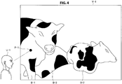
- FIG. 4 is a diagram for describing an example of selecting the farm animal B.
- a field of view V-1 of the user U-1 is illustrated. Further, there are farm animals B-1 to B-3 in the field of view V-1.
- the communication unit 130 transmits the direction of the display control device 10 and the position information of the display control device 10 to the server 20.
- the information acquiring unit 211 decides the farm animals B-1 to B-3 located in the field of view V- 1 on the basis of the direction of the display control device 10, the position information of the display control device 10, and the position information of each of the plurality of farm animals. If the individual information and the position information of each of the farm animals B-1 to B-3 located in the field of view V-1 are acquired by the information acquiring unit 211, the information providing unit 212 provides the individual information and the position information of each of the farm animals B-1 to B-3 located in the field of view V-1 to the display control device 10 via the communication unit 230. Further, the individual information will be described later in detail.
- the communication unit 130 receives the individual information and the position information of each of the farm animals B-1 to B-3 located in the field of view V-1.
- the user U-1 desires to know the individual information of the farm animal B-1 among the farm animals B-1 to B-3 is assumed.
- the selecting unit 112 determines that the line of sight P-1 matches with the farm animal B-1 on the basis of the line of sight P-1 and the position information of each of the farm animal B-1 to B-3.
- the selecting unit 112 selects the farm animal B-1 with which the line of sight P-1 matches.
- the display control unit 111 may control display of a pointer to the position of the line of sight P-1. Accordingly, the user U-1 can easily comprehend the position of the line of sight P-1 in accordance with the position of the pointer.
- the selection of the farm animal B-1 has been described, but the farm animal B-2 and the farm animal B-3 can also be selected similarly to the farm animal B-1.
- the selecting unit 112 immediately selects the farm animal B-1 with which the line of sight P-1 matches in a case in which the line of sight P-1 matches with the farm animal B-1.
- the selecting unit 112 may not immediately select the farm animal B-1 in a case in which the line of sight P-1 matches with the farm animal B-1.
- the selecting unit 112 may select the farm animal B-1 with which the line of sight P-1 matches during a predetermined period of time or more in a case in which the line of sight P-1 matches with the farm animal B-1 during a predetermined period of time or more.
- FIG. 5 is a diagram for describing another example of selecting the farm animal B.
- the field of view V-1 of the user U-1 is illustrated.
- farm animals B-1 to B-3 in the field of view V-1.
- An operation before the individual information and the position information of each of the farm animals B-1 to B-3 located in the field of view V-1 are received by the display control device 10 is similarly to that in the example described with reference to FIG. 4 .
- the user U-1 desires to know the individual information of the farm animal B-1 among the farm animals B-1 to B-3 is considered.
- the user U-1 performs a motion corresponding to the position at which the farm animal B-1 is located in the field of view V-1 (for example, a wraparound action to a position at which the farm animal B-1 is located in the field of view V-1).
- the wraparound action may be an action of wrapping around from the left (that is, an action of drawing clockwise when viewed from above).
- the selecting unit 112 determines that the farm animal B-1 is located at a position corresponding to the wraparound action on the basis of the wraparound action and the position information of each of the farm animals B-1 to B-3. The selecting unit 112 selects the farm animal B-1 located at the position corresponding to the wraparound action. Further, in a case in which the user U-1 is considered to desire to know the individual information of the farm animal B-3 located at the far right in the field of view V-1, the wraparound action may be an operation that wraps around from the right (that is, an action of drawing counterclockwise when viewed from above).
- the farm animal B-1 is selected on the basis of the line of sight of the user U-1 (or on the basis of the wraparound action) has been described.
- the technique for selecting the farm animal is not limited to this example.
- the selecting unit 112 may select a farm animal located in a predetermined region in the field of view V-1.
- the predetermined region in the field of view V-1 may be a central region in the field of view V-1 or may be other regions in the field of view V-1.
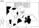
- FIG. 6 is a diagram for describing the AR display example of the individual information of the farm animal B-1 and a first determination example in a case in which the farm animal B-3 is hard to see.
- a field of view V-2 of the user U-1 is illustrated.
- a case in which the farm animal B-1 is selected by the selecting unit 112 as described above is assumed.
- the display control unit 111 controls the AR display of the individual information I-11 of the farm animal B-1 selected by the selecting unit 112. For example, it is sufficient if the display control unit 111 causes individual information I-11 of the farm animal B-1 selected by the selecting unit 112 to be AR-displayed at a position corresponding to the position at which the farm animal B-1 is located in the field of view V-2 (for example, a position near the position at which the farm animal B-1 is located in the field of view V-2). According to such a display, it is easy for the user U-1 to comprehend a correspondence between the farm animal B-1 and ARI-11 of the farm animal B-1 in the field of view V-2.
- the selecting unit 112 may select the farm animal (the farm animal B-2 or the farm animal B-3) different from the currently selected the farm animal B-1. For example, the selecting unit 112 may select the next farm animal in order from the farm animal close to the user U-1 (for example, in the order of the farm animal B-2 and the farm animal B-3) each time the switching manipulation is performed.
- the individual information I-11 of the farm animal B-1 includes a birth (for example, a birth may include a date of birth and a birth state), a weight, a medical history, a medication, and a body condition (BC) is mainly assumed.
- a birth for example, a birth may include a date of birth and a birth state
- a weight for example, a weight
- a medical history for example, a medication
- a body condition mainly assumed.
- the information included in the individual information 1-11 of the farm animal B-1 is not limited thereto.
- the display control unit 111 controls display of information (hereinafter also referred to as "link information") connecting the farm animal B-1 in the field of view V-2 with the individual information I-11 of the farm animal B-1.
- link information As the link information is displayed, it is easier for the user U-1 to further comprehend the correspondence between the farm animal B-1 in the field of view V-2 and the individual information I-11 of the farm animal B-1.
- the individual information I-11 of the farm animal B-1 may be unconditionally AR-displayed at a position corresponding to the position at which the farm animal B-1 is located in the field of view V-2.
- a case in which the farm animal B-1 is moved is also assumed.
- the individual information 1-11 may not be seen well.
- the display control unit 111 decides the position of the individual information I-11 of the farm animal B-1 on the basis of the position of the farm animal B-1 in the field of view V-2.
- the display control unit 111 may fix the position of the individual information I-11 of the farm animal B-1 in a case in which the farm animal B-1 is moving.
- the link information is displayed.
- the position at which the individual information I-11 of the farm animal B-1 is fixed is not particularly limited.
- the display control unit 111 causes "statistical information display,” “learn more,” and “voice record” to be displayed, as selected items H, at a position corresponding to the position of the individual information I-11 of the farm animal B-1. If a selection manipulation on "statistical information display” is performed, statistical information obtained by comparing the farm animal B-1 with other farm animals is displayed.
- the detailed information may be a name of a doctor who has treated a disease of the farm animal B-1, may be a method of treating a disease of the farm animal B-1, may be information of parents of the farm animal B-1, or may be a delivery status of the farm animal B-1.
- a voice input of comments related to the farm animal B-1 is received, and the comments related to the farm animal B-1 is recorded in the storage unit 150 by voice.
- the comments related to the farm animal B-1 may be any kind of comments.
- the comments related to the farm animal B-1 may be comments related to a scheduled work to be performed later on the farm animal B-1.
- the comments related to the farm animal B-1 which are recorded in storage unit 150 by voice can be reproduced and referred to later.
- the determining unit 113 determines whether or not it is hard for the user U-1 to see the farm animals B-1 to B-3. For example, the determining unit 113 performs determination of whether or not at least a part of the farm animal B-3 is shielded by another object with reference to the position of the user U-1 (hereinafter also referred to as "shielding determination")).
- FIG. 6 illustrates an example in which the determining unit 113 determines that a part of the farm animal B-3 is shielded by the farm animal B-1 when viewed the position of the user U-1. A similar determination may be performed on the farm animal B-1 and the farm animal B-2.
- the display control unit 111 may display shielding notification information V-1 indicating the presence of the farm animal B-3 shielded by another object.
- the shielding notification information M-1 may be information such as "there is a shielded cow," but specific content of the shielding notification information M-1 is not limited.
- the display position of the shielding notification information M-1 is not limited, but as illustrated in FIG. 6 , the display position of the shielding notification information M-1 is a position corresponding to the position of the farm animal B-3 shielded in the field of view V-2 (for example, in the vicinity of the position of the farm animal B-3 or the like).
- the shielding determination can be performed in any method.
- the shielding determination may be performed using an image. More specifically, in a case in which the display control device 10 includes an imaging device that images the field of view of the user U-1, the determining unit 113 determines that a part of the farm animal B-3 is shielded by another object in a case in which a first condition that a partial region of the farm animal B-3 are shown in a captured image of the field of view is satisfied, and a second condition that a region of another object is shown near the partial regions is satisfied.
- the captured image may be a three-dimensional space data detected by a depth sensor.
- a partial region of the farm animal B-3 is shown in the captured image of the field of view, and the region of the farm animal B-1 is shown near to the partial region.
- the determining unit 113 may determine that a part of the farm animal B-3 is shielded by the farm animal B-1.
- a third condition that a face of the farm animal B-3 is not shown in the captured image of the field of view may be added to the first condition and the second condition, or the first condition may be replaced with a condition that a ratio of the farm animal B-3 shown in the captured image of the field of view to the whole farm animal B-3 is less than a predetermined ratio.
- the shielding determination may be performed using the position information of each of the user U-1 and the farm animal B-1.
- the determining unit 113 may determine that at least part of the farm animal B-3 is shielded by another object in a case in which the directions of the farm animal B-3 and another object coincide or are close to each other on the basis of the position of the user U-1, and the farm animal B-3 is farther than another object on the basis of the position of the user U-1.
- the determining unit 113 may determine that a part of the farm animal B-3 is shielded by the farm animal B-1. Further, the position information of each of the user U-1 and the farm animal B-1 to B-3 can be obtained as described above.
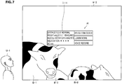
- FIG. 7 is a diagram for describing the AR display example of the individual information of the farm animal B-1 and the second determination example in a case in which it is difficult to see the farm animal B-3.
- a field of view V-3 of the user U-1 is illustrated.
- the display control unit 111 controls the AR display of the individual information I-11 of the farm animal B-1 selected by the selecting unit 112.
- the determining unit 113 determines whether or not it is difficult for the user U-1 to see the farm animals B-1 to B-3. As an example, the determining unit 113 determines whether or not a predetermined display manipulation by the user U-1 is performed (for example, because the farm animal B-3 is hard to see).
- the predetermined display manipulation is not limited. However, as described above, the hands-free manipulation is desirable in work sites for the farm animals or the like.
- a predetermined display manipulation be a manipulation other than the touch manipulation and the button manipulation by the user U-1 (that is, it is desirable for the determining unit 113 to perform determination on the basis of whether or not a condition other than the presence or absence of the touch manipulation and the button manipulation by the user U-1 is satisfied).
- the predetermined display manipulation may be an action of the user looking up (that is, an operation of tilting the top of the head of the user backward).
- the predetermined display manipulation is not limited to this example.
- the predetermined display manipulation may be an overlooking action (that is, an operation of tilting the top of the head of the user forward).
- the predetermined display manipulation may be an action of wrapping around from the left (that is, an action of drawing clockwise when viewed from above) or may be an action of wrapping around from the right (that is, an action of drawing counterclockwise when viewed from above).
- the predetermined display manipulation may be an action of looking in from below (that is, an action of tilting the top of the head in the left direction or the right direction) or may be a predetermined voice spoken by the user U-1(for example, a speech).
- the predetermined display manipulation may be a continuation of these actions exceeding a predetermined period of time.
- FIG. 8 is a diagram for describing the AR display example of the individual information of the farm animal B-1 and a determination example in a case in which the farm animal B-1 to B-3 are hard to see.
- a field of view V-4 of the user U-1 is illustrated. Since the user U-1 and farm animals B-1 to B-3 are far from each other, the farm animals B-1 to B-3 are located in a small size in the field of view V-4.
- the display control unit 111 controls the AR display of the individual information I-11 of the farm animal B-1 selected by the selecting unit 112.
- the determining unit 113 determines whether or not it is difficult for the user U-1 to see the farm animals B-1 to B-3. As an example, in a case in which a distance between the user U-1 and the farm animals B-1 to B-3 exceeds a predetermined distance, it may be difficult for the user U-1 to see the farm animals B-1 to B-3. Therefore, the determining unit 113 determines whether or not a distance between the user U-1 and one of the farm animal B-1 to B-3 (for example, the farm animal B-1 located at the shortest distance from the user U-1 among the farm animals B-1 to B-3 B-1) exceeds a predetermined distance.
- the display example of the individual information of the farm animal B-1 and the determination example in a case in which the farm animal B-1 to B-3 are hard to see have been described above.
- the determination example in a case in which the farm animals B-1 to B-3 are hard to see is not limited to these examples.
- any of the farm animals B-1 to B-3 takes a predetermined posture (for example, a sitting posture, a posture of turning back to the user U-1, or the like) or a predetermined motion (for example, movement or the like), it may be difficult for the user U-1 to see the farm animal.
- the determining unit 113 may determine whether or not a condition that one of the farm animals B-1 to B-3 takes a predetermined posture or a condition that a predetermined motion is being performed is satisfied.
- the farm animal B-2 takes a sitting posture. At this time, it is sufficient if the determining unit 113 determines that a condition that the farm animal B-2 takes a sitting posture is satisfied.
- the display control unit 111 controls the VR display of an image related to the farm animal B-3.
- the farm animal B-3 in which individual information I-31 ( FIG. 11 ) is AR-displayed can be easily comprehended by the user U-1.
- the display control unit 111 performs control such that the VR display of the image related to the farm animal B-3 is displayed in a form different from a form in which the farm animal B-3 shielded in the field of view is visually recognized by the user U-1.
- an example in which the individual information of the farm animal B-1 is also continuously AR-displayed in a case in which the image related to the farm animal B-3 is VR-displayed will be mainly described.
- the image related to the farm animal B-3 is VR-displayed
- the individual information of the farm animal B-1 may not be displayed.
- a mode in which the image related to the farm animal B-3 is VR-displayed and the mode in which the individual information of the farm animal B-1 is AR-displayed may be switched.
- an overhead image will be described as an example. An angle of a space shown in the overhead image may be controllable by a manipulation by the user.
- the image related to the farm animal B-3 is not limited to such an example.
- the image related to the farm animal B-3 may be 3D data which is created in advance.
- the image related to the farm animal B-3 may be an image obtained by imaging the farm animal B-3 from the head side, may be an image obtained by imaging the farm animal B-3 from the side, or may be an image obtained by imaging the farm animal B-3 from the buttock side.
- the image related to the farm animal B-3 may be the entire image captured by the external sensor 30 or may be a part of an image captured by the external sensor 30.
- the image related to the farm animal B-3 may be a synthetic image of images captured by a plurality of external sensors 30 or may be an image captured by any one of a plurality of external sensors 30.
- the external sensor 30 may perform imaging once at a certain time point in the past. In this case, the image related to the farm animal B-3 does not change particularly from a certain time point in the past. However, the external sensor 30 may constantly perform imaging and update an old image with the latest image. In this case, the image related to the farm animal B-3 may be changed over time. Therefore, the user U-1 can comprehend a growth state of the farm animal B-3 by looking at the images related to the farm animal B-3. Further, the image related to the farm animal B-3 may be a predetermined object (for example, a picture, a mark, or the like) located at a position of the farm animal B-3 in a map or a two-dimensional image.
- a predetermined object for example, a picture, a mark, or the like
- FIG. 9 is a diagram illustrating a VR display example of the overhead image.
- a field of view V-5 of the user U-1 is illustrated.
- the display control unit 111 performs control such that the AR display in which the individual information of the farm animal B-3 is associated with the farm animal B-3.
- the AR display may be display of causing the user U-1 to virtually recognize when the individual information of the farm animal B-3 is displayed in the space visually recognized by the user U-1 (for example, the link information or the like).
- the display control unit 111 performs control such that the AR display in which the individual information of the farm animal B-3 is associated with the farm animal B-3.
- the AR display may be display
- the farm animal B-3 is hard to see in a case in which it is determined that the farm animal B-3 is shielded by the farm animal B-1, in a case in which a predetermined display manipulation is performed, a case in which the distance between the user U-1 and one of the farm animals B-1 to B-3 exceeds a predetermined distance, or the like.
- the display control unit 111 causes an overhead image T-1 for selecting a shielded farm animal B-3 to be VR-displayed as illustrated in FIG. 9 .
- the VR display may be any one of at least an overhead image corresponding to the farm animal B-3, a three-dimensional image corresponding to the farm animal B-3, a captured image including an image in which the farm animal B-3 is not shielded.
- the overhead image T-1 includes an image R-31 related to the farm animal B-3 that is determined to be hard to see.
- the overhead image T-1 includes an image R-11 related to the farm animal B-1 and an image R-21 related to the farm animal B-2.
- the selecting unit 112 determines that the line of sight P-2 matches with the image R-31 related to the farm animal B-3 on the basis of the line of sight P-2 and the position information of the image R-31 (related to the farm animal B-3) in the overhead image T-1.
- the selecting unit 112 selects the farm animal B-3 corresponding to the image R-31 (for the farm animal B-3) with which the line of sight P-2 matches.
- the farm animal B-3 determined to be hard to see can be easily selected through the VR display of the image R-31 related to the farm animal B-3.
- the farm animal B-3 can be easily selected through the VR display of the image R-31 related to the farm animal B-3.
- the VR display of the image R-31 related to the farm animal B-3 it is unnecessary for the user U-1 to approach the farm animal B-3 and to scan the barcode, thus the work efficiency of the user U-1 is improved.
- the selecting unit 112 immediately selects the farm animal B-3 corresponding to the image R-31 (related to the farm animal B-3) with which the line of sight P-2 matches has been described above.
- the selecting unit 112 may select the farm animal B-3 corresponding to the image R-31 (related to the farm animal B-3) with which the line of sight P-2 matches for more than a predetermined period of time when the line of sight P-2 matches with the image R-31 related to the farm animal B-3 for more than a predetermined period of time.
- the display control unit 111 may control display of information indicating the presence of the image R-31 related to the farm animal B-3. Accordingly, if the user U-1 seeing the information indicating the presence of the image R-31 related to the farm animal B-3 performs a predetermined display manipulation, the image R-31 related to the farm animal B-3 is VR-displayed in accordance with the predetermined display manipulation.
- the overhead image T-1 may be displayed in a case in which the user U-1 performs an action of looking down (for example, since the external sensor 30 installed above is hard to see from the user U-1 in a case in which the user U-1 is outdoors or the like).
- the overhead image T-1 may be displayed in a case in which the user U-1 performs an action of looking up (for example, since the external sensor 30 installed above is seen well from the user U-1 in a case in which the user U-1 is outdoors or the like).
- the display control unit 111 may erase the farm animal B-1 shielding at least a part of the farm animal B-3 from the field of view V-5 and replace the farm animal B-3 located in the field of view V-5 with the image related to the farm animal B-3.
- the image related to the farm animal B-3 be an image of a posture which is easily visually recognized.
- the image of the posture which is easily visually recognized may be an image obtained by imaging the farm animal B-3 from the side, may be an image obtained by imaging the farm animal B-3 from the head side, or may be an image obtained by imaging the farm animal B-3 from the buttock side.
- the image of the posture which is easily visually recognized be an image obtained by imaging a posture that the farm animal B-3 is standing.
- a type of image may change depending on a type of display manipulation. For example, in a case in which the user U-1 performs an action of wrapping around from the left or the right, the image obtained by imaging the farm animal B-3 from the side may be displayed. Further, in a case in which the user U-1 performs an action of looking in from the bottom, the image obtained by imaging the farm animal B-3 from the bottom may be VR-displayed. Alternatively, a type of image may be designated by voice (for example, a speech) spoken by the user U-1.
- any one of the farm animals B-1 to B-3 takes a predetermined posture or in a case in which any one of the farm animals B-1 to B-3 is performing a predetermined motion, it may be difficult for the user U-1 to see the farm animal.
- the farm animal B-2 taking a sitting posture, it may be difficult for the user U-1 to see the farm animal B-2.
- the display control unit 111 controls the VR display of the image related to the farm animal B-2.
- the image related to the farm animal B-2 be an image of a posture which is easily visually recognized.
- the image of the posture which is easily visually recognized may be an image obtained by imaging the farm animal B-2 from the side, may be an image obtained by imaging the farm animal B-2 from the head side, or may be an image obtained by imaging the farm animal B-2 from the buttock side. Further, it is desirable that the image of the posture which is easily visually recognized be an image obtained by imaging a posture that the farm animal B-2 is standing.
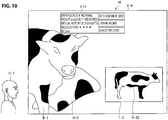
- FIG. 10 is a diagram illustrating a VR display example of an image obtained by imaging the farm animal B-2 from the side.
- a field of view V-6 of the user U-1 is illustrated.
- the display control unit 111 causes a horizontal direction image T-2 obtained by imaging the farm animal B-2 from the side as illustrated in FIG. 10 .
- the horizontal direction image T-2 includes an image R-22 related to the farm animal B-2 determined to be hard to see.
- the selecting unit 112 determines that the line of sight matches with the image R-22 related to the farm animal B-2 on the basis of the line of sight and the position information of the image R-22 (related to the farm animal B-2) in the horizontal direction image T-2.
- the selecting unit 112 selects the farm animal B-2 corresponding to the image R-22 (related to the farm animal B-2) with which the line of sight matches.
- the VR display example of the horizontal direction image T-2 has been described above.
- the display control unit 111 controls the AR display of the individual information of the farm animal B-3.
- the display control unit 111 controls the AR display of the individual information of the farm animal B-2.
- the AR display example of the individual information of the farm animal B-3 will be described.
- FIG. 11 is a diagram illustrating an AR display example of the individual information of the farm animal B-3 selected by the selecting unit 112.
- the display control unit 111 controls the AR display of the individual information I-31 of the farm animal B-3 selected by selecting unit 112. Further, in the example illustrated in FIG. 11 , it is VR-displayed at a position at which an image R 32 corresponding to the farm animal B-3 is seen well (for example, a position not overlapping other farm animals located in the field of view V-7) in field of view V-7, and link information connecting an image R32 with the individual information 1-31 is displayed. Accordingly, it is easy for the user U-1 to further comprehend the farm animal B-3 corresponding to the individual information I-31.
- the example in which the overhead image T-1 is not displayed in a case in which the farm animal B-3 is selected by the selecting unit 112 has been described above.
- a timing at which the overhead image T-1 is not displayed is not limited to this example.
- the overhead image T-1 may not be displayed by canceling a predetermined display manipulation by the user U-1.
- the overhead image T-1 may not be displayed when the user U-1 performs an action of looking down.
- the overhead image T-1 may not be displayed when the user U-1 performs an action of looking up.
- the VR display example of the image related to the farm animal B-3 has been described above.
- the display control unit 111 may control display of the identification information of the farm animal in addition to the individual information of the farm animal. Accordingly, the user U-1 can more easily identify the farm animal located in the field of view by looking at the identification information of the farm animal.
- an ID assigned by the user U-1 is displayed as an example of the identification information of the farm animal will be described.
- FIG. 12 is a diagram illustrating a display example of the ID assigned by the user U-1.
- a field of view V-8 of the user U-1 is illustrated.
- the farm animals B-1 to B-3 are located in the field of view V-8.
- the identification number of the IOT device of the farm animal B-2 is transmitted from the wearable device 40 worn on the farm animal B-2 to the server 20
- the ID corresponding to the identification number of the IOT device is transmitted from the server 20 to the display control device 10 as the ID of the farm animal B-2.
- the display control unit 111 controls the display of the ID of the farm animal B-2. Specifically, if the position information of the farm animal B-2 is transmitted from the server 20, in the display control device 10, the display control unit 111 performs control such that the ID of the farm animal B-2 is displayed at a position at which the farm animal B-2 is located in the field of view V-8 on the basis of the position information of the farm animal B-2, the direction of the display control device 10 detected by the detecting unit 120, and the position information of the display control device 10.
- the display control unit 111 causes the ID of the farm animal B-2 to be displayed superimposed on the farm animal B-2 in the field of view V-8. Accordingly, it is easy to comprehend the correspondence between the ID of the farm animal B-2 and the farm animal B-2 located in the field of view V-8. More specifically, as illustrated in FIG. 12 , it is sufficient if the display control unit 111 causes a number Z in which the ID of the farm animal B-2 is described to be displayed superimposed on the body of the farm animal B-2 in the field of view V-8 (for example, an abdomen). Further, the identification information of the farm animal B-1 and the identification information of the farm animal B-3 can also be displayed similarly to the identification information of the farm animal B-2.
- the number of individual information of the farm animal which is AR-displayed at one time is not limited to one.
- the individual information of each of a plurality of farm animals may be simultaneously AR-displayed.
- the display control unit 111 may control the AR display of the individual information of each of a plurality of farm animals in a case in which there are a plurality of farm animals in the field of view.
- An example in which the individual information of each of a plurality of farm animals is simultaneously AR-displayed will be described below.
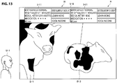
- FIG. 13 is a diagram illustrating an example in which the individual information of each of a plurality of farm animals is simultaneously AR-displayed.
- a field of view V-9 of the user U-1 is illustrated.
- the farm animal B-1 and B-2 are located in the field of view V-9.
- the display control unit 111 may control the AR display of the individual information I-11 of the farm animal B-1 and individual information I-21 of the farm animal B-2.
- the display control unit 111 may control the AR display of the individual information I-11 of the farm animal B-1 and the individual information I-21 of the farm animal B-2.
- FIG. 13 illustrates an example in which there are two pieces of individual information which are AR-displayed. At this time, a situation in which the two pieces of individual information overlap each other does not occur. However, as the number of individual information to be displayed increases, a situation in which a plurality of pieces of individual information overlaps each other may occur. In such a situation, a situation that there is individual information which is at least partially not displayed may occur.
- FIG. 14 is a diagram illustrating an example of a situation in which a plurality of pieces of individual information overlaps each other.
- a field of view V-10 of the user U-1 is illustrated.
- a farm animal B-4 is located in the field of view V-10 in addition to the farm animals B-1 and B-2.
- the display control unit 111 may control the AR display of the individual information I-11 of the farm animal B-1, the individual information I-21 of the farm animal B-2, and individual information I-41 of the farm animal B-4.
- the display control unit 111 may control the AR display of the individual information I-11 of the farm animal B-1, the individual information I-21 of the farm animal B-2, and the individual display I-41 of the farm animal B-4.
- the individual information I-21 of the farm animal B-2 and the individual information I-41 of the farm animal B-4 overlap each other.
- the display control unit 111 stops the AR display of the individual information of each of a plurality of farm animals in a case in which the density of the individual information of each of a plurality of farm animals is higher than a predetermined density.
- the display control unit 111 controls the VR display of the image related to each of a plurality of farm animals in a case in which the density of the individual information of each of a plurality of farm animals is higher than a predetermined density.
- the display control unit 111 may stop the AR display of the individual information I-41 of the farm animal B-4 and control the VR display of the image related to the farm animal B-4. Further, the display control unit 111 may stop the AR display of the individual information I-11 of the farm animal B-1 and control the VR display of the image related to the farm animal B-2. Further, the display control unit 111 may stop the AR display of the individual information I-21 of the farm animal B-2 and control the VR display of the image related to the farm animal B-2.
- the display control unit 111 may control the display or the non-display of the individual information of each of a plurality of farm animals in a case in which the density of the individual information of each of a plurality of farm animals is higher than a predetermined density.
- the display control unit 111 may hide only the individual information 1-41 which is partially not seen.
- the display control unit 111 may hide only the individual information with which the line of sight of the user U-1 does not match.
- the display control unit 111 may control a display positions of the individual information of each of a plurality of farm animals in a case in which the density of the individual information of each of a plurality of farm animals is higher than a predetermined density. For example, the display control unit 111 may select a position that does not overlap with the individual information I-11 and the individual information I-21 as the display position of the individual information I-41 which is not partially seen.
- the display control unit 111 may control an information amount of the individual information of each of a plurality of farm animals in a case in which the density of the individual information of each of a plurality of farm animals is higher than a predetermined density. For example, the display control unit 111 may reduce the information amount of the individual information of each of a plurality of farm animals in a case in which the density of the individual information of each of a plurality of farm animals is higher than a predetermined density.
- FIG. 15 is a diagram illustrating an example of reducing the information amount of the individual information of each of a plurality of farm animals.
- a field of view V-11 of the user U-1 is illustrated.
- the farm animal B-4 is located in the field of view V-11 in addition to the farm animals B-1 and B-2.
- the display control unit 111 may control the AR display of the individual information I-22 of the farm animal B-2 and the individual information I-42 of the farm animal B-4 whose information amount is reduced. Thereby, it is possible to prevent a situation in which a plurality of pieces of individual information overlaps each other.
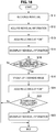
- FIG. 16 is a flowchart illustrating the first example of the operation of the display control system 1 according to an embodiment of the present disclosure. Further, the flowchart illustrated in FIG. 16 merely indicates an example of the operation of the display control system 1. Therefore, the operation of the display control system 1 is not limited to the operation example of the flowchart illustrated in FIG. 16 .
- the server 20 specifies the position information of the farm animals B-1 to B-N on the basis of the information specifying the position information of the farm animals B-1 to B-N.
- the individual recognition is performed by the server 20 (S11).
- the information acquiring unit 211 acquires the individual information and the position information of each of the farm animals B-1 to B-3 located in the field of view V-1 (S12)
- the information providing unit 212 provides the individual information and the position information of each of the farm animals B-1 to B-3 located in the field of view V-1 to the display control device 10 via the communication unit 230.
- the selecting unit 112 acquires a looking-at point at which the user U-1 is looking (S13)
- the farm animal B-1 in which the user U-1 is interested is selected on the basis of the looking-at point and the position information of each of the farm animals B-1 to B-3.
- the display control unit 111 controls the AR display of the individual information I-11 of the selected the farm animal B-1 (S14).
- the determining unit 113 determines whether or not one of the farm animals B-1 to B-3 is shielded by another object (S15).
- the display control unit 111 controls the VR display of the overhead image (S16), and the selecting unit 112 acquires the looking-at point of the user U-1 (S21), and in a case in which the farm animal shielded by another object is selected by the selecting unit 112 using the VR display (for example, since the looking-at point is on the overhead image) ("Yes" in S22), the display control unit 111 controls the display of the individual information of the farm animal (S23), and ends the operation.
- the display control unit 111 ends the operation. On the other hand, the display control unit 111 ends the operation in a case in which there is no farm animal shielded by another object ("No" in S15).
- FIG. 17 is a flowchart illustrating the second example of the operation of the display control system 1 according to an embodiment of the present disclosure. Further, the flowchart illustrated in FIG. 17 merely indicates an example of the operation of the display control system 1. Therefore, the operation of the display control system 1 is not limited to the operation example of the flowchart illustrated in FIG. 17 .
- S11 to S14 can be executed as described with reference to FIG. 16 .
- the determining unit 113 determines whether or not the posture of the user U-1 is a predetermined posture (S17). In a case in which the posture of the user U-1 is a predetermined posture ("Yes" in S17), S16 and S21 to S23 are executed as described with reference to FIG. 16 , and the operation ends. On the other hand, in a case in which the posture of the user U-1 is a predetermined posture ("No" in S17), the display control unit 111 ends the operation.
- FIG. 18 is a flowchart illustrating the third example of the operation of the display control system 1 according to an embodiment of the present disclosure. Further, the flowchart illustrated in FIG. 18 merely indicates an example of the operation of the display control system 1. Therefore, the operation of the display control system 1 is not limited to the operation example of the flowchart illustrated in FIG. 18 .
- S11 to S14 can be executed as described with reference to FIG. 16 .
- the determining unit 113 determines whether or not the distance between the user U-1 and the farm animals B-1 to B-3 (for example, the distance from the user U-1 to the farm animal closes to the user U-1) exceeds a threshold value (S18).
- the display control unit 111 executes S16 and S21 to S23 as described with reference to FIG. 16 , and ends the operation.
- the display control unit 111 ends the operation.
- FIG. 19 is a flowchart illustrating the modified example of the first example of the operation of the display control system 1 according to an embodiment of the present disclosure. Further, the flowchart illustrated in FIG. 19 merely indicates an example of the operation of the display control system 1. Therefore, the operation of the display control system 1 is not limited to the operation example of the flowchart illustrated in FIG. 19 .
- the server 20 specifies the position information of the farm animals B-1 to B-N on the basis of the information specifying the position information of the farm animals B-1 to B-N.
- the individual recognition is performed by the server 20 (S11).
- the information acquiring unit 211 acquires the individual information and the position information of each of the farm animals B-1 to B-3 located in the field of view V-1 (S12)
- the information providing unit 212 provides the individual information and the position information of each of the farm animals B-1 to B-3 located in the field of view V-1 to the display control device 10 via the communication unit 230.
- the determining unit 113 determines whether or not one of the farm animals B-1 to B-3 is shielded by another object (S15). In the case in which there is a farm animal shielded by another object exists ("Yes” in S15), S16 and S21 to S23 are executed as described with reference to FIG. 16 , and the operation ends. On the other hand, in a case in which there is no farm animal shielded by another object ("No" in S15), the operation ends.
- FIG. 20 is a flowchart illustrating the modified example of the second example of the operation of the display control system 1 according to an embodiment of the present disclosure. Further, the flowchart illustrated in FIG. 20 merely indicates an example of the operation of the display control system 1. Therefore, the operation of the display control system 1 is not limited to the operation example of the flowchart illustrated in FIG. 20 .
- S11 to S12 can be executed as described with reference to FIG. 16 .
- the determining unit 113 determines whether or not the posture of the user U-1 is a predetermined posture (S17).
- S17 a predetermined posture
- S16 and S21 to S23 are executed as described with reference to FIG. 16 , and the operation ends.
- S13 to S14 are executed and the operation ends.
- FIG. 21 is a flowchart illustrating the modified example of the third example of the operation of the display control system 1 according to an embodiment of the present disclosure. Further, the flowchart illustrated in FIG. 21 merely indicates an example of the operation of the display control system 1. Therefore, the operation of the display control system 1 is not limited to the operation example of the flowchart illustrated in FIG. 21 .
- S11 to S12 can be executed as described with reference to FIG. 16 .
- the determining unit 113 determines whether or not the distance between the user U-1 and the farm animals B-1 to B-3 (for example, the distance from the user U-1 to the farm animal closes to the user U-1) exceeds a threshold value (S18).
- S18 a threshold value
- S16 and S21 to S23 are executed as described with reference to FIG. 16 , and the operation ends.
- S13 to S14 are executed and the display control unit 111 ends the operation.
- one target object whose AR information is presented to the user is a farm animal
- one target object whose AR information is presented to the user is not limited to a farm animal.
- one target object whose AR information is presented to the user may be an athlete.
- An example in which one target object whose AR information is presented to the user is an athlete will be described below.
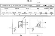
- FIG. 22 is a diagram for describing an example in which one target object whose AR information is presented to the user is an athlete.
- a situation in which a coach of a group competition corresponds to the user U-1 described above and gives an instruction to players while viewing information related to the players is assumed.
- players L-1 to L-3 are located in a field of view G-2 of the coach.
- display of information related to the athlete L-3 (hereinafter also referred to as "player information") J-31 is controlled by the display control unit 111.
- display of information related to the players on the inner side may be controlled by the display control unit 111 in accordance with the wraparound action of the coach such that the information related to the player on the inner side is visible to the coach. Further, the information related to the player which is far away may be enlarged by the display control unit 111, and the VR display may be controlled.
- the VR display of the image may be controlled by the display control unit 111 when the coach performs an action of looking up or an action of looking down.
- the image may be a three-dimensional image captured by the external sensor 30 or may be a map or a two-dimensional image.
- the coach can select the player through the line of sight and give an instruction to the selected player from the headset.
- display of a movement trajectory of the player may be controlled by the display control unit 111 and confirmed by the coach.
- the display control unit 111 may control display of the player on the inner side by sequential transmission by the coach.
- the display control unit 111 in the field of view G-2, a part of the player L-3 is shielded by the player L-1, but the entire player L-3 is visible in the field of view G-1 after the field of view G-2 in accordance with the sequential transmission manipulation by the coach.
- the player L-1 may be deleted by the display control unit 111, or the player L-3 may be rearranged at a position which is not shielded by the player L-1 by the display control unit 111 (may be VR-displayed).
- a previous action of an athlete may be replayed by the display control unit 111 in accordance with an instruction by voice, an action of matching the line of sight with a GUI menu, an instruction by gesture, or the like.
- the information to be displayed includes a war experience, a physical characteristic, a training situation, a moving picture of past games or exercises, analysis results thereof, or the like. Further, it is possible to replay similar formations performed in the past and perform a strategy simulation through the VR using a prediction algorithm.
- Meta information may be superimposed on an object visible to the user under a microscope by the display control unit 111.
- one target object whose AR information is presented to the user may be an animal living in a zoo.
- one target object whose AR information is presented to the user may be a fish being cultured.
- the meta information may be superimposed on an object which can be freely moved by the user (such as stationery, tools, small devices, or the like) by the display control unit 111 if needed. Accordingly, it is possible for the user to search for the object moved by the other user without permission. At this time, the meta information of the object placed in a direction the user is looking at may be controlled by the display control unit 111.
- the output unit 160 may output the information by voice. For example, in a case in which the user touches a cow, the output unit 160 may read a condition of the cow aloud. Further, in a case in which the condition of the cow is bad, the output unit 160 may output an alert. Further, in a case in which the output unit 160 fails to recognize the target object located in the field of view of the user, a plurality of target object candidates may be output. At this time, the user may select one candidate from a plurality of candidates.
- FIG. 23 is a block diagram illustrating the hardware configuration example of the display control device 10 according to the embodiment of the present disclosure.
- the display control device 10 includes a central processing unit (CPU) 901, read only memory (ROM) 903, and random access memory (RAM) 905.
- the control unit 110 can be realized by the CPU 901, the ROM 903 and the ROM 905.
- the display control device 10 may include a host bus 907, a bridge 909, an external bus 911, an interface 913, an input device 915, an output device 917, a storage device 919, a drive 921, a connection port 923, and a communication device 925.
- the display control device 10 may include an imaging device 933 and a sensor 935, as necessary.
- the display control device 10 may include a processing circuit such as a digital signal processor (DSP) or an application specific integrated circuit (ASIC), alternatively or in addition to the CPU 901.
- DSP digital signal processor
- ASIC application specific integrated circuit
- the CPU 901 serves as an arithmetic processing device and a control device, and controls the overall operation or a part of the operation of the display control device 10 according to various programs recorded in the ROM 903, the RAM 905, the storage device 919, or a removable recording medium 927.
- the ROM 903 stores programs, operation parameters, and the like used by the CPU 901.
- the RAM 905 temporarily stores programs used when the CPU 901 is executed, and parameters that change as appropriate when executing such programs.
- the CPU 901, the ROM 903, and the RAM 905 are connected with each other via the host bus 907 configured from an internal bus such as a CPU bus.
- the host bus 907 is connected to the external bus 911 such as a Peripheral Component Interconnect/Interface (PCI) bus via the bridge 909.
- PCI Peripheral Component Interconnect/Interface
- the input device 915 is a device operated by a user such as a button.
- the input device 915 may include a mouse, a keyboard, a touchscreen, a button, a switch, a lever and the like.
- the input device 915 may include a microphone configured to detect voice of users.
- the input device 915 may be a remote control device that uses, for example, infrared radiation and another type of radio waves.
- the input device 915 may be external connection equipment 929 such as a mobile phone that corresponds to an operation of the display control device 10.
- the input device 915 includes an input control circuit that generates input signals on the basis of information which is input by a user to output the generated input signals to the CPU 901.
- a user inputs various types of data and indicates a processing operation to the display control device 10 by operating the input device 915.
- the imaging device 933 (to be described later) may function as the input device by capturing an image of movement of hands of a user or capturing a finger of a user. In this case, a pointing position may be decided in accordance with the movement of the hands or a direction of the finger.
- the detecting unit 120 can be realized by the input device 915.
- the output device 917 includes a device that can visually or audibly report acquired information to a user.
- the output device 917 may be, for example, a display device such as a liquid crystal display (LCD), an organic electro-luminescence (EL), a sound output device such as a speaker or a headphone, or the like.
- the output device 917 may include a plasma display panel (PDP), a projector, a hologram, a printer, or the like.
- the output device 917 outputs a result obtained through a process performed by the display control device 10, in the form of text or video such as an image, or sounds such as voice and audio sounds.
- the output device 917 may include a light or the like to light the surroundings. Further, the output unit 160 can be realized by the output device 917.
- the storage device 919 is a device for data storage that is an example of the storage unit of the display control device 10.
- the storage device 919 includes, for example, a magnetic storage device such as a hard disk drive (HDD), a semiconductor storage device, an optical storage device, or a magneto-optical storage device.
- the storage device 919 stores therein various data and programs executed by the CPU 901, and various data acquired from an outside.
- the drive 921 is a reader/writer for the removable recording medium 927 such as a magnetic disk, an optical disc, a magneto-optical disk, and a semiconductor memory, and built in or externally attached to the display control device 10.
- the drive 921 reads out information recorded on the mounted removable recording medium 927, and outputs the information to the RAM 905.
- the drive 921 writes the record into the mounted removable recording medium 927.
- connection port 923 is a port used to directly connect equipment to the display control device 10.
- the connection port 923 may be a USB (Universal Serial Bus) port, an IEEE1394 port, and a Small Computer System Interface (SCSI) port, or the like.
- the connection port 923 may be an RS-232C port, an optical audio terminal, an HDMI (registered trademark) (High-Definition Multimedia Interface) port, and so on.
- the connection of the external connection equipment 929 to the connection port 923 makes it possible to exchange various kinds of data between the display control device 10 and the external connection equipment 929.
- the communication device 925 is a communication interface including, for example, a communication device for connection to the network 931.
- the communication device 925 may be, for example, a wired or wireless local area network (LAN), Bluetooth (registered trademark), or a communication card for a wireless USB (WUSB).
- the communication device 925 may also be, for example, a router for optical communication, a router for asymmetric digital subscriber line (ADSL), or a modem for various types of communication.
- the communication device 925 transmits and receives signals in the Internet or transmits signals to and receives signals from another communication device by using a predetermined protocol such as TCP/IP.
- the network 931 to which the communication device 925 connects is a network established through wired or wireless connection.
- the network 931 is, for example, the Internet, a home LAN, infrared communication, radio communication, or satellite communication.
- the communication unit 130 can be realized by the communication device 925.
- the imaging device 933 is a device that captures images of a real space by using an image sensor such as a charge coupled device (CCD) or a complementary metal oxide semiconductor (CMOS), and various members such as a lens for controlling image formation of a subject image onto the image sensor, and generates the captured images.
- the imaging device 933 may capture a still image or a moving image. Further, the detecting unit 120 can be realized by the imaging device 933.
- the sensor 935 is various sensors such as a ranging sensor, an acceleration sensor, a gyro sensor, a geomagnetic sensor, a vibration sensor, an optical sensor, and a sound sensor.
- the sensor 935 acquires information regarding a state of the display control device 10 such as a posture of a housing of the display control device 10, and information regarding an environment surrounding the display control device 10 such as luminous intensity and noise around the display control device 10.
- the sensor 935 may include a global positioning system (GPS) sensor that receives GPS signals to measure latitude, longitude, and altitude of the device. Further, the detecting unit 120 can be realized by the sensor 935.
- GPS global positioning system
- a display control device including a display control unit configured to control display of information related to one target object located in a field of view of a user, wherein, in a case in which it is determined that at least a part of one target object is shielded by another object on the basis of a position of the user, the display control unit controls display of an image related to one target object. Accordingly, it is possible for the user to easily comprehend one target object whose AR information is presented to the user.
- the position of each component is not particularly limited as long as the operations of the display control device 10 and the server 20 are realized.
- some or all of the blocks (the display control unit 111, the selecting unit 112, and the determining unit 113) included in the control unit 110 in the display control device 10 may be installed in the server 20 or the like.
- one or more relay devices (not illustrated) that perform the processes of some of the respective units may be installed in the display control system 1.
- the relay device may be, for example, a smartphone carried by the user U-1.
- the relay device includes a communication circuit for communicating with the display control device 10 and the server 20 and a processing circuit for performing some of the processes performed by the respective blocks in the embodiment in the housing of the relay device. Further, when the relay device receives predetermined data from, for example, the communication unit 230 of the server 20, performs the processes of some of the respective units, and transmits data to the communication unit 130 of the display control device 10 on the basis of a processing result or performs communication and processes in an opposite direction, effects similar to those of the embodiment of the operations of the display control device 10 and the server 20 are obtained.
- the example of connecting the target object (for example, the farm animal) with the individual information of the target object located in the real world in the field of view of the user has been described above.
- the connection of the target object located in the real world and the individual information of the target object may not be performed.
- the target object is a farm animal
- the user can visually recognize an identification number of a farm animal from a sensor worn on the farm animal
- a correspondence between the target object and the individual information can be comprehended using a position at which the identification number is visually recognized. According to such a configuration, a processing load imposed by the display control device 10 can be reduced.
- present technology may also be configured as below.
Landscapes
- Engineering & Computer Science (AREA)
- Theoretical Computer Science (AREA)
- General Physics & Mathematics (AREA)
- Physics & Mathematics (AREA)
- Life Sciences & Earth Sciences (AREA)
- Computer Hardware Design (AREA)
- Environmental Sciences (AREA)
- General Engineering & Computer Science (AREA)
- Animal Husbandry (AREA)
- Biodiversity & Conservation Biology (AREA)
- Computer Graphics (AREA)
- Software Systems (AREA)
- Zoology (AREA)
- Birds (AREA)
- Biophysics (AREA)
- Human Computer Interaction (AREA)
- User Interface Of Digital Computer (AREA)
- Processing Or Creating Images (AREA)
- Controls And Circuits For Display Device (AREA)
Applications Claiming Priority (2)
| Application Number | Priority Date | Filing Date | Title |
|---|---|---|---|
| JP2016231232 | 2016-11-29 | ||
| PCT/JP2017/036186 WO2018100874A1 (fr) | 2016-11-29 | 2017-10-04 | Dispositif de commande d'affichage, procédé de commande d'affichage et programme |
Publications (2)
| Publication Number | Publication Date |
|---|---|
| EP3550525A1 true EP3550525A1 (fr) | 2019-10-09 |
| EP3550525A4 EP3550525A4 (fr) | 2019-11-27 |
Family
ID=62241483
Family Applications (1)
| Application Number | Title | Priority Date | Filing Date |
|---|---|---|---|
| EP17875520.3A Withdrawn EP3550525A4 (fr) | 2016-11-29 | 2017-10-04 | Dispositif de commande d'affichage, procédé de commande d'affichage et programme |
Country Status (4)
| Country | Link |
|---|---|
| US (1) | US10923083B2 (fr) |
| EP (1) | EP3550525A4 (fr) |
| JP (1) | JP6958570B2 (fr) |
| WO (1) | WO2018100874A1 (fr) |
Families Citing this family (8)
| Publication number | Priority date | Publication date | Assignee | Title |
|---|---|---|---|---|
| WO2020109348A1 (fr) * | 2018-11-28 | 2020-06-04 | Evonik Operations Gmbh | Procédé de commande d'un élevage de bétail |
| KR102539579B1 (ko) * | 2018-12-18 | 2023-06-05 | 삼성전자주식회사 | 정보의 표시 영역을 적응적으로 변경하기 위한 전자 장치 및 그의 동작 방법 |
| US11568530B2 (en) * | 2018-12-21 | 2023-01-31 | Precision Livestock Technologies, Inc. | System and method to analyse an animal's image for market value determination |
| US10945097B1 (en) * | 2019-09-06 | 2021-03-09 | Andy Doyle Jones | Method of implementing a lightweight, electronic ear tag for location tracking and geo-fencing tasks |
| US11755999B2 (en) * | 2019-10-24 | 2023-09-12 | Accenture Global Solutions Limited | Artificial intelligence based project implementation |
| JP7517405B2 (ja) * | 2020-03-06 | 2024-07-17 | ソニーグループ株式会社 | 情報処理装置、情報処理方法および情報処理プログラム |
| KR102452932B1 (ko) * | 2022-01-20 | 2022-10-11 | 정우석 | 지도 기반 유기동물 관리 플랫폼 서비스 제공 시스템 |
| CN115361526A (zh) * | 2022-08-16 | 2022-11-18 | 苏州数智赋农信息科技有限公司 | 一种基于图像处理的养猪场巡检系统及方法 |
Family Cites Families (10)
| Publication number | Priority date | Publication date | Assignee | Title |
|---|---|---|---|---|
| US8963954B2 (en) * | 2010-06-30 | 2015-02-24 | Nokia Corporation | Methods, apparatuses and computer program products for providing a constant level of information in augmented reality |
| US20120176525A1 (en) * | 2011-01-12 | 2012-07-12 | Qualcomm Incorporated | Non-map-based mobile interface |
| US9256711B2 (en) * | 2011-07-05 | 2016-02-09 | Saudi Arabian Oil Company | Systems, computer medium and computer-implemented methods for providing health information to employees via augmented reality display |
| JP2013037476A (ja) * | 2011-08-05 | 2013-02-21 | Nikon Corp | 観察装置、観察方法、及び撮像装置 |
| JP5942422B2 (ja) * | 2011-12-26 | 2016-06-29 | キヤノンマーケティングジャパン株式会社 | 情報処理装置、その制御方法及びプログラム |
| KR101957943B1 (ko) * | 2012-08-31 | 2019-07-04 | 삼성전자주식회사 | 정보 제공 방법 및 이를 위한 정보 제공 차량 |
| JP6064544B2 (ja) | 2012-11-27 | 2017-01-25 | ソニー株式会社 | 画像処理装置、画像処理方法、プログラム及び端末装置 |
| JP6291927B2 (ja) * | 2014-03-13 | 2018-03-14 | 富士通株式会社 | 特定方法、特定プログラム、特定装置および特定システム |
| US9928658B2 (en) * | 2015-11-02 | 2018-03-27 | International Business Machines Corporation | Overlay for camera field of vision |
| US10043238B2 (en) * | 2016-01-21 | 2018-08-07 | International Business Machines Corporation | Augmented reality overlays based on an optically zoomed input |
-
2017
- 2017-10-04 US US16/463,009 patent/US10923083B2/en not_active Expired - Fee Related
- 2017-10-04 WO PCT/JP2017/036186 patent/WO2018100874A1/fr not_active Ceased
- 2017-10-04 JP JP2018553686A patent/JP6958570B2/ja not_active Expired - Fee Related
- 2017-10-04 EP EP17875520.3A patent/EP3550525A4/fr not_active Withdrawn
Also Published As
| Publication number | Publication date |
|---|---|
| JP6958570B2 (ja) | 2021-11-02 |
| US20200090627A1 (en) | 2020-03-19 |
| WO2018100874A1 (fr) | 2018-06-07 |
| JPWO2018100874A1 (ja) | 2019-10-17 |
| US10923083B2 (en) | 2021-02-16 |
| EP3550525A4 (fr) | 2019-11-27 |
Similar Documents
| Publication | Publication Date | Title |
|---|---|---|
| EP3550525A1 (fr) | Dispositif de commande d'affichage, procédé de commande d'affichage et programme | |
| US11080882B2 (en) | Display control device, display control method, and program | |
| US10089793B2 (en) | Systems and methods for providing real-time composite video from multiple source devices featuring augmented reality elements | |
| JP6348741B2 (ja) | 情報処理システム、情報処理装置、情報処理プログラム、および情報処理方法 | |
| US20150379777A1 (en) | Augmented reality providing system, recording medium, and augmented reality providing method | |
| CN110506249B (zh) | 信息处理设备、信息处理方法和记录介质 | |
| CN102859470B (zh) | 对象控制装置、对象控制方法以及集成电路 | |
| CN203224887U (zh) | 显示控制设备 | |
| US9311742B1 (en) | Navigating an avatar through a virtual world in a motion capture simulation environment | |
| JP6342024B1 (ja) | 仮想空間を提供するための方法、当該方法をコンピュータに実行させるためのプログラム、および当該プログラムを実行するための情報処理装置 | |
| US20150355463A1 (en) | Image display apparatus, image display method, and image display system | |
| CN107479699A (zh) | 虚拟现实交互方法、装置及系统 | |
| JP7224488B2 (ja) | インタラクティブ方法、装置、デバイス、及び記憶媒体 | |
| JP2023027126A (ja) | データ処理プログラム、データ処理方法、および、データ処理装置 | |
| JP2013200793A (ja) | 情報処理装置、情報処理方法およびプログラム | |
| JP6348732B2 (ja) | 情報処理システム、情報処理装置、情報処理プログラム、および情報処理方法 | |
| US20200060240A1 (en) | Display control device, display control method, and program | |
| KR20230070308A (ko) | 웨어러블 장치를 이용한 제어가능한 장치의 위치 식별 | |
| EP3528024B1 (fr) | Dispositif de traitement d'informations, procédé de traitement d'informations et programme | |
| WO2018100878A1 (fr) | Dispositif de commande de présentation, procédé de commande de présentation, et programme | |
| JPWO2019026919A1 (ja) | 画像処理システム、画像処理方法、及びプログラム | |
| WO2019123744A1 (fr) | Dispositif de traitement d'informations, procédé de traitement d'informations et programme | |
| US20200058271A1 (en) | Display control device, display control method, and program | |
| US20250371827A1 (en) | Information processing device, program, and information processing system | |
| JP6974253B2 (ja) | 仮想空間を提供するための方法、当該方法をコンピュータに実行させるためのプログラム、および当該プログラムを実行するための情報処理装置 |
Legal Events
| Date | Code | Title | Description |
|---|---|---|---|
| STAA | Information on the status of an ep patent application or granted ep patent |
Free format text: STATUS: THE INTERNATIONAL PUBLICATION HAS BEEN MADE |
|
| PUAI | Public reference made under article 153(3) epc to a published international application that has entered the european phase |
Free format text: ORIGINAL CODE: 0009012 |
|
| STAA | Information on the status of an ep patent application or granted ep patent |
Free format text: STATUS: REQUEST FOR EXAMINATION WAS MADE |
|
| 17P | Request for examination filed |
Effective date: 20190522 |
|
| AK | Designated contracting states |
Kind code of ref document: A1 Designated state(s): AL AT BE BG CH CY CZ DE DK EE ES FI FR GB GR HR HU IE IS IT LI LT LU LV MC MK MT NL NO PL PT RO RS SE SI SK SM TR |
|
| AX | Request for extension of the european patent |
Extension state: BA ME |
|
| A4 | Supplementary search report drawn up and despatched |
Effective date: 20191024 |
|
| RIC1 | Information provided on ipc code assigned before grant |
Ipc: G09G 5/36 20060101ALI20191018BHEP Ipc: G06F 3/01 20060101ALI20191018BHEP Ipc: G09G 5/00 20060101ALI20191018BHEP Ipc: G09G 5/377 20060101ALI20191018BHEP Ipc: G06T 19/00 20110101AFI20191018BHEP |
|
| DAV | Request for validation of the european patent (deleted) | ||
| DAX | Request for extension of the european patent (deleted) | ||
| RAP3 | Party data changed (applicant data changed or rights of an application transferred) |
Owner name: SONY GROUP CORPORATION |
|
| STAA | Information on the status of an ep patent application or granted ep patent |
Free format text: STATUS: THE APPLICATION IS DEEMED TO BE WITHDRAWN |
|
| 18D | Application deemed to be withdrawn |
Effective date: 20210501 |