EP3550575A1 - Elektrischer wicklungsdraht, drehmaschinenspule damit und verfahren zur herstellung eines elektrischen wicklungsdrahtes - Google Patents
Elektrischer wicklungsdraht, drehmaschinenspule damit und verfahren zur herstellung eines elektrischen wicklungsdrahtes Download PDFInfo
- Publication number
- EP3550575A1 EP3550575A1 EP17875577.3A EP17875577A EP3550575A1 EP 3550575 A1 EP3550575 A1 EP 3550575A1 EP 17875577 A EP17875577 A EP 17875577A EP 3550575 A1 EP3550575 A1 EP 3550575A1
- Authority
- EP
- European Patent Office
- Prior art keywords
- wire
- coil
- winding
- flat
- electric wire
- Prior art date
- Legal status (The legal status is an assumption and is not a legal conclusion. Google has not performed a legal analysis and makes no representation as to the accuracy of the status listed.)
- Granted
Links
Images





Classifications
-
- H—ELECTRICITY
- H01—ELECTRIC ELEMENTS
- H01B—CABLES; CONDUCTORS; INSULATORS; SELECTION OF MATERIALS FOR THEIR CONDUCTIVE, INSULATING OR DIELECTRIC PROPERTIES
- H01B7/00—Insulated conductors or cables characterised by their form
- H01B7/08—Flat or ribbon cables
- H01B7/0876—Flat or ribbon cables comprising twisted pairs
-
- H—ELECTRICITY
- H02—GENERATION; CONVERSION OR DISTRIBUTION OF ELECTRIC POWER
- H02K—DYNAMO-ELECTRIC MACHINES
- H02K3/00—Details of windings
- H02K3/04—Windings characterised by the conductor shape, form or construction, e.g. with bar conductors
- H02K3/28—Layout of windings or of connections between windings
-
- H—ELECTRICITY
- H01—ELECTRIC ELEMENTS
- H01B—CABLES; CONDUCTORS; INSULATORS; SELECTION OF MATERIALS FOR THEIR CONDUCTIVE, INSULATING OR DIELECTRIC PROPERTIES
- H01B7/00—Insulated conductors or cables characterised by their form
-
- H—ELECTRICITY
- H01—ELECTRIC ELEMENTS
- H01B—CABLES; CONDUCTORS; INSULATORS; SELECTION OF MATERIALS FOR THEIR CONDUCTIVE, INSULATING OR DIELECTRIC PROPERTIES
- H01B7/00—Insulated conductors or cables characterised by their form
- H01B7/04—Flexible cables, conductors, or cords, e.g. trailing cables
-
- H—ELECTRICITY
- H01—ELECTRIC ELEMENTS
- H01F—MAGNETS; INDUCTANCES; TRANSFORMERS; SELECTION OF MATERIALS FOR THEIR MAGNETIC PROPERTIES
- H01F27/00—Details of transformers or inductances, in general
- H01F27/28—Coils; Windings; Conductive connections
-
- H—ELECTRICITY
- H01—ELECTRIC ELEMENTS
- H01F—MAGNETS; INDUCTANCES; TRANSFORMERS; SELECTION OF MATERIALS FOR THEIR MAGNETIC PROPERTIES
- H01F5/00—Coils
-
- H—ELECTRICITY
- H02—GENERATION; CONVERSION OR DISTRIBUTION OF ELECTRIC POWER
- H02K—DYNAMO-ELECTRIC MACHINES
- H02K1/00—Details of the magnetic circuit
- H02K1/06—Details of the magnetic circuit characterised by the shape, form or construction
- H02K1/12—Stationary parts of the magnetic circuit
-
- H—ELECTRICITY
- H02—GENERATION; CONVERSION OR DISTRIBUTION OF ELECTRIC POWER
- H02K—DYNAMO-ELECTRIC MACHINES
- H02K15/00—Processes or apparatus specially adapted for manufacturing, assembling, maintaining or repairing of dynamo-electric machines
- H02K15/04—Processes or apparatus specially adapted for manufacturing, assembling, maintaining or repairing of dynamo-electric machines of windings prior to their mounting into the machines
-
- H—ELECTRICITY
- H02—GENERATION; CONVERSION OR DISTRIBUTION OF ELECTRIC POWER
- H02K—DYNAMO-ELECTRIC MACHINES
- H02K15/00—Processes or apparatus specially adapted for manufacturing, assembling, maintaining or repairing of dynamo-electric machines
- H02K15/04—Processes or apparatus specially adapted for manufacturing, assembling, maintaining or repairing of dynamo-electric machines of windings prior to their mounting into the machines
- H02K15/043—Processes or apparatus specially adapted for manufacturing, assembling, maintaining or repairing of dynamo-electric machines of windings prior to their mounting into the machines winding flat conductive wires or sheets
-
- H—ELECTRICITY
- H02—GENERATION; CONVERSION OR DISTRIBUTION OF ELECTRIC POWER
- H02K—DYNAMO-ELECTRIC MACHINES
- H02K3/00—Details of windings
- H02K3/02—Windings characterised by the conductor material
-
- H—ELECTRICITY
- H02—GENERATION; CONVERSION OR DISTRIBUTION OF ELECTRIC POWER
- H02K—DYNAMO-ELECTRIC MACHINES
- H02K3/00—Details of windings
- H02K3/04—Windings characterised by the conductor shape, form or construction, e.g. with bar conductors
-
- H—ELECTRICITY
- H02—GENERATION; CONVERSION OR DISTRIBUTION OF ELECTRIC POWER
- H02K—DYNAMO-ELECTRIC MACHINES
- H02K3/00—Details of windings
- H02K3/04—Windings characterised by the conductor shape, form or construction, e.g. with bar conductors
- H02K3/12—Windings characterised by the conductor shape, form or construction, e.g. with bar conductors arranged in slots
- H02K3/14—Windings characterised by the conductor shape, form or construction, e.g. with bar conductors arranged in slots with transposed conductors, e.g. twisted conductors
-
- H—ELECTRICITY
- H02—GENERATION; CONVERSION OR DISTRIBUTION OF ELECTRIC POWER
- H02K—DYNAMO-ELECTRIC MACHINES
- H02K21/00—Synchronous motors having permanent magnets; Synchronous generators having permanent magnets
- H02K21/12—Synchronous motors having permanent magnets; Synchronous generators having permanent magnets with stationary armatures and rotating magnets
- H02K21/24—Synchronous motors having permanent magnets; Synchronous generators having permanent magnets with stationary armatures and rotating magnets with magnets axially facing the armatures, e.g. hub-type cycle dynamos
Definitions
- the present invention relates to an electric wire for winding, a coil for a rotating machine using the same, and a method of manufacturing the electric wire for winding.
- a print motor using a disk-like armature As a rotating machine for increasing the space factor, for example, a print motor using a disk-like armature is known.
- the print motor forms a coil by etching a copper foil on an insulated resin plate.
- an etching-type coil even if the thickness of copper is increased by piling up plating. Therefore, there is a limit to increasing of motor output.
- Non-Patent Literature 1 Patent Literature 1
- Non-patent Literature 1 Yuta Yamamoto and two others "High torque densitization of direct drive-type synchronous motor using flat wire coil with high space factor" issued on March 5, 2013, (National Convention) The Institute of Electrical Engineers of Japan, National Convention Proceedings in 2013, Page 64 to 65 , Dissertation No. 5-036
- a litz wire in which a large number of thin round wires is twisted together is flexible and easily wrapped around a small core, and it is preferable to apply to a compact motor.
- a coil is formed by winding the litz wire, many gaps are created, and that point is similar to winding a round wire. That is, the coil made by winding a litz wire does not necessarily improve a space factor with respect to the coil made by winding a round wire.
- an electric wire for winding is a band-shaped flat wire or square wire and composed of a two-layered or two multiple-layered flat braided wire in which one enameled wire or a plurality of enameled wires bundled in parallel or in a litz shape is braided and molded flat.
- an electric wire for winding is a band-shaped flat wire or square wire and composed of a two-layered or two multiple-layered flat braided wire in which one enameled wire or a plurality of enameled wires bundled in parallel or in a litz shape is braided and molded flat, and the electric wire for winding is wound.
- a plurality of connection bundles is provided at both ends of the wound electric wire for winding, and the number of turns of the coil may be made variable by connecting at least a part of a plurality of the connection bundles in series or in parallel between other coils or between connection bundles in the same coil. Further, the connection of the connection bundle at a coil connection point with another coil or at a wire connection point in the same coil is performed via a relay, and at least a part of a plurality of sets of the connection bundles can be switched and connected in series or in parallel by switching the relay. Further, a coil thickness of the coil for a rotating machine can be halved by displacing coils bent in opposite directions in an out-of-flux region outside a flux passage region so as not to overlap between the flux passage regions.
- a method of manufacturing an electric wire for winding includes the steps of round braiding one enameled wire or a plurality of enameled wires bundled in parallel or in a litz shape into a single-layered or double or more layered cylindrical braided wire, flat braiding into two-layered or two multiple-layered flat braided wire by molding the cylindrical braided wire flat, and shaping the flat braided wire as a flat wire or a square wire.
- a cylindrical braided wire is formed using a core
- a cylindrical braided wire is molded flat after removing the core.
- an electric wire for winding is a braided enamel wire, it has excellent flexibility, and it is easy to wind for forming a coil. Therefore, for forming a coil for a rotating machine, the electric wire for winding can be wound around a small core, and winding work becomes easy even with a small core or coreless.
- the electric wire for winding of the present invention molded into a flat wire or a square wire by a flat braided wire is a bundle of thin insulated enameled wires. Therefore, when it is used in a coil for a rotating machine, the generation of an eddy current is suppressed, and the heat generation associated with the generation of an eddy current is also suppressed as compared with a flat wire or a square wire having the same conductor cross-sectional area, manufactured by rolling a round wire.
- a flat wire or square wire has an effect of improving heat dissipation due to surface contact. Therefore, it is possible to flow much more current. In other words, since an electric resistance is reduced, much more current can flow, and the efficiency as a coil for a rotating machine is improved.
- the electric wire for winding is a flat wire or square wire
- a space factor when the electric wire is used for a coil in a rotating machine is increased by, for example, 20% to 30%
- a resistance value can be made lower than in the case of a coil consisting of round wires having the same size, and the number of turns can be increased, and ampere turns per unit cross sectional area can be increased.
- a coil with the same performance resistance value, number of turns
- the coil formed with the electric wire for winding is provided with a plurality of connection bundles of braided enameled wires, even after it is completed as a coil, by selectively connecting at least a part of the connection bundles in series or in parallel, the number of turns as a coil can be freely changed.
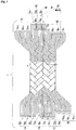
- Fig. 1 shows an embodiment of an electric wire for winding according to the present invention.
- An electric wire 1 for winding is a flat wire or square wire and composed of a two-layered or two multiple-layered flat braided wire in which one enameled wire 1a or a plurality of enameled wires 1a bundled in parallel or in a litz shape is braided and molded flat.
- the electric wire 1 for winding forms a cylindrical round braided wire by braiding one enameled wire 1a or a plurality of the enameled wires 1a or a plurality of twisted wires as one unit (refer to Fig. 2(A) ).
- a hollow portion is compressed and molded flat to form a two-layered or two multiple-layered flat braided wire, and shaped as a flat wire or a square wire (refer to Fig. 2(B) ).
- a dimension in the drawing is the width of the flat braided wire
- B dimension is the thickness (length on the edge side/short side) of the flat braided wire.
- Reference sings 1A to 1D in the drawing denote connection bundles forming one unit of connection, and 1b denotes a bundle of the enameled wires 1a or one unit of twisted wires, and for distinguishing each bundle of enameled wires, for example, the bundles are indicated by 1b 1 to 1b 12 with 1 to 12 attached.
- the electric wire 1 for winding according to the present embodiment is braided, for example, into twelve bundles (1b 1 to 1b 12 ) by two bundles of parallel braiding with four enameled wires 1a as one bundle by a braiding machine. Further, a double cylindrical round braided wire 1' (refer to Fig. 2(A) ) is formed by further round braiding after round braiding. Next, for example, the hollow portion is crushed by a press to compress the hollow portion to form a four-layered flat braided wire (refer to Fig. 2(B) ).
- the electric wire 1 for winding including flat braided wires is composed of forty eight enameled wires 1a (four wires in one bundle, twelve bundles), and three bundles are connected in parallel to form one as connection bundles, four connection bundles 1A to 1D are formed.
- the core 2 is preferably used. It is possible to braid without using the core 2, but in the case of braiding using the core 2, the arrangement of the enameled wires 1a when a flat braided wire is used is aligned and densely arranged, and therefore a space factor can be further increased. Further, when the hollow portion of the round braided wire 1' is compressed and formed flat while being crushed by a press, it is preferable to pull in the longitudinal direction orthogonal to the width direction of the braided wire. As a result, since the flat braided wire is shaped into a flat wire or a square wire in a stretched state, even when tension is applied when winding a coil, the wire does not stretch at that time.
- a flat braided wire is molded flat after forming a cylindrical braided wire by round braiding an enameled wire, and the flat braided wire is shaped as a flat wire or a square wire. Therefore, a flat or square electric wire for winding consisting of a flat braided wire, which is an assembly of enameled wires with a small cross-sectional area can be easily manufactured.
- a plurality of connection bundles forming one unit of connection is formed without special processing.
- the electric wires 1 for winding illustrated in Fig. 1 are braided as a bundle of a plurality of enameled wires 1a disposed side by side, but this is not particularly limited thereto, and a plurality of the enameled wires 1a may be twisted together, for example, a litz wire to be braided as one unit (one bundle), and each one enameled wire 1a may be braided.
- the braiding method in the present embodiment is a double round braid having four layers in the flat braided wire state. In some cases, a single braid having two layers in a flat braided wire state or a triple braid having six layers in a flat braided wire state may be used.
- the electrical wires can be braided in quadruple by double round braiding on a state of double round braiding, and it may be crushed to form a flat braided wire with eight layers and eight connection bundles and then molded into a flat wire or a square wire.
- the method of crushing the round braided wire 1' may be, for example, either from the longitudinal direction or from the lateral direction, or may be alternately crushed longitudinally or horizontally as illustrated in Fig. 2(C) .
- two bundles are braided in parallel by crossing two bundles upper and lower, but this is not particularly limited thereto, and one bundle or three or more bundles may be braided.
- the enameled wire is a varnish of insulating resin baked on a conductor, and various insulating resins can be used, and for example, polyurethane copper wire (UEW), polyester copper wire (PEW), polyester imide copper wire (EIW), polyamide imide copper wire (AIW), polyimide copper wire (PIW), and the like are generally used, but it is not limited to these.
- a polyurethane copper wire is preferably used. In the case of this polyurethane copper wire, since an enamel film is peeled off when heat is applied, the enamel film can be peeled off and connected only by immersing the coil in a solder bath. Therefore, the connection work for each large number of wires is facilitated.
- the enameled wire 1a moves by a tension applied to braid the enameled wire 1a and a pressure at the time of pressing, and a wire interval is varied and misaligned. Consequently, peeling of enamel coating of the enameled wire 1a is prevented, and disturbance of the arrangement of the enameled wire 1a is effectively prevented.
- the material of the enameled wire 1a is generally a copper wire, but this is not particularly limited thereto, and an aluminum wire, OFC (oxygen-free copper wire), nickel-plated soft copper wire, and the like can also be used.
- the enameled wire 1a is not required to have a specific cross-sectional shape and may be a round wire, a square wire, or a flat wire. Further, the shape of the round braided wire before being processed into a flat braided wire is not particularly limited to a cylinder illustrated in Fig. 2(A) and may be an elliptical cylinder or a polygonal cylinder.
- the enameled wire 1a be sufficiently thin compared to a cross-sectional area of a conductor as the electric wire 1 for winding, and a wire diameter can maintain sufficient flexibility in the case of forming a flat braided wire.
- a round enameled wire having a diameter of about 0.05 to 1.2 mm, a square enameled wire or a polygonal enameled wire having a diameter of about 0.05 mm ⁇ 0.05 mm to 1.2 mm ⁇ 1.2 mm, and the like which are generally marketed can be used.
- the wire diameter may be appropriately selected for example within a range of 0.05 to 1 mm in order to achieve flexibility as a flat braided wire, increase in a space factor, and reduce an eddy current loss, and within a range of about 0.05 to 0.6 mm, preferably about 0.05 to 0.5 mm, and more preferably about 0.05 to 0.26 mm when relatively large output is not required.
- Fig. 2(A) twelve bundles are braided, for example, by parallel braiding two bundles of each four enameled wires 1a having 0.3 mm ⁇ diameter around a vinyl rod or a pipe core 2, and a flat braided wire is formed which is molded flat by compressing a hollow portion after forming the cylindrical round braided wire 1' by drawing the cores 2.
- the electric wire 1 for winding in Fig. 1 is formed which is flexible and composed of a flat wire with a width of 3.6 mm and a thickness of 1.2 mm.
- the enameled wires as the flat braided wire are aligned and densely disposed, such that a space factor of the electric wire for winding in forming a coil can be further increased.
- Fig. 3 indicates an example of forming a trapezoidal coil suitable for using in a face-to face motor (referred to as a flat motor) by using the electric wire 1 for winding according to the present invention.
- the coil 3 of this type it is desirable that the edge side (short side side of the width B) of the flat braided wire 1 faces a magnet. Therefore, the coil is molded by winding in a spiral such that the long side surface (surface of the width A) of the flat braided wire is overlapped.
- the number of turns of the coil 3 can be changed by connecting a plurality of connection bundles, for example, four connection bundles 1A to 1D in series or in parallel between the connection bundles of other coils or between other connection bundles in the same coil.
- Figs. 3(A) to 3(C) indicate examples of a single-wound coil in which one electric wire 1 for winding is spirally wound from the inner side, and finished winding on the outer side.
- the coil 3 has, for example, a coil winding start 3s consisting of four connection bundles 1A to 1D on the inner peripheral side, and a coil winding end 3f on the outer peripheral side.
- the number of turns of the coil 3 can be changed by connecting the connection bundles 1A to 1D in series or in parallel with other coils or with connection bundles in the same coil. For example, by coil-connecting in series three connection bundles among four connection bundles 1A to 1D of the coil on the winding start 3s side to three connection bundles among four connection bundles 1A to 1D of the coil on the winding end 3f side at a coil connection point 4, a coil consisting of the winding start 3s of one connection bundle and the winding end 3f of one connection bundle can be formed. Note that, in the middle coil, the four connection bundles 1A to 1D are all connected to corresponding four connection bundles 1A to 1D of other coils.
- Figs. 3(D) to 3(F) indicate examples of a double-wound coil 3' (also referred to as ⁇ -winding or double pancake) in which the winding start 3s and the winding end 3f are positioned on the outer periphery of a coil.
- the double-wound coil 3' two coils are continuously molded by winding in a spiral one electric wire 1 for winding having a plurality of connection bundles, for example, four connection bundles 1A to 1D from the inner side to the right and left in two rows and finishing winding on the outer side (refer to Fig. 3(F) ).
- the double-wound coil 3' is a coil element in which a conductor is spirally wound in upper and lower two layers.
- the number of turns as a coil can be changed by connecting at least a part of the four connection bundles 1A to 1D in series or in parallel between other coils or between connection bundles in the same coil.
- three connection bundles in the winding start 3s on the coil outer periphery are coil-connected in series to three connection bundles on the winding end 3f side of the coil outer periphery by coil connection at the coil connection point 4 to form a double-wound coil 3' consisting of the winding start 3s of one bundle and the winding end 3f of one bundle.
- the electric wire 1 for winding is molded into a coil, it is solidified.
- the respective wires and further the respective bundles are adhered and fixed to each other by an insulating resin, a paint or the like.
- the electric wire 1 for winding is solidified with an insulating paint made of a heat resistant resin or the like at about 120°C.
- the flexibility of the electric wire for winding can be utilized to easily and tightly wind the coil without gaps, and after forming into a coil shape, the coil is fixed by adhesion etc. such that it can be easily formed into a desired coil shape.
- the single- or double-wound coil 3, 3' configured as described above can form, for example, an axial gap type or radial gap type coil for a rotating machine, which is used for a permanent magnet type rotating machine, by wave winding or lap-winding.
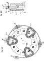
- Fig. 4 illustrates an example of an axial gap type coil using the above-described coil and a method of connecting the coil.
- Fig. 4(A) indicates a state in which the coils in one phase is disposed with respect to an annually disposed permanent magnet with six poles.
- the coils in one phase include three turns of the coils 3, 3', and four connection bundles 1A to 1D from the winding end 3f of the coil on the winding start side to the winding start 3s of the next coil are connected at a wire connection point 5, and further, four connection bundles 1A to 1D from the winding end 3f of the middle coil to the winding start 3s of the coil on the winding end side are connected at the wire connection point 5.
- connection bundles 1A to 1D between the two coils are respectively connected in a branched state, but the connection bundles 1A to 1D may be connected together as one, that is, connected as one connection bundle.
- the connection bundles 1A to 1D may be connected together as one, that is, connected as one connection bundle.
- the coils 3, 3' are disposed in a gap portion between a pair of the magnets 6 disposed so as to face each other, such that an edge, that is a short side surface faces the magnets (in other words, such that the long side surface of the electric wire 1 for winding is parallel to a rotor shaft 9).
- reference sign 6 denotes a permanent magnet
- 7 denotes a yoke
- 8 denotes a magnetic or nonmagnetic magnet holder
- 9 denotes a rotor shaft.
- a coil circuit including a plurality of the coils 3, 3' disposed annularly along the magnet 6, it is not limited to the above-described embodiment of the coil with an outer winding start and an outer winding end, and a coil may start winding on the inner side in the radial direction and finish winding on the inner side.
- connection bundles 1A to 1D which are the winding start of the coils 3, 3' on the winding start side
- the connection bundles 1A to 1C are connected in series at the wire connection point 5 to three of the four connection bundles 1A to 1D which are the winding end of the coils 3, 3' on the winding end side, for example, the connection bundles 1B to 1D
- a series connected coil can be formed which includes the winding start 3s of one connection bundle, for example, 1D and the winding end 3f of one connection bundle, for example, 1A.
- connection bundles which are the winding start 3s of the coils 3, 3' on the winding start side for example, 1A and 1B and 1C and 1D are connected in parallel to each other, and the four connection bundles 1A to 1D between the coils 3, 3' are connected each other in series at the wire connection point 5.
- two bundles, for example, 1C and 1D, in the connection bundles which are the winding end 3f of the last coil 3, 3' is coil-connected at the wire connection point 5 to one of two pairs of the connection bundles connected in parallel at the coil winding start, for example, 1A and 1B, to form a parallel connected winding circuit, in which two connection bundles are connected in series.
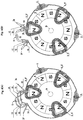
- connection of a plurality of connection bundles for example, four connection bundles 1A to 1D, at the coil connection point 4 or the wire connection point 5 of each coil 3, 3' may be switched using relay connection or the like in some cases.
- a relay circuit 10 it is possible to switch to a series connected coil as illustrated in Fig. 6(A) and to switch to a parallel connected coil in an instant as illustrated in Fig. 6(B) .
- One of the connection bundles 1A to 1D which are the winding start 3s and the winding end 3f is branched into a connection bundle connected to the relay circuit 10 and a connection bundle as the winding start 3s.
- Fig. 7 illustrates an example of the arrangement of coils and magnets for three phases of an axial gap type coil.
- the coil can be configured as a three-phase alternating current rotating machine (permanent magnet type rotating machine), or can be configured as a DC rotating machine by adding a commutator.
- three single-would coils 3, 3' are disposed circumferentially in order of three phases, and the coils 3, 3' in the same phase are coil-connected, and four connection bundles 1A to 1D that are the winding start 3s and the winding end 3f are drawn out from the coil 3, 3' at the end of each phase.
- the coils 3, 3' are consolidated and integrated with resin and adhesive, and the arrangement relationship with the magnet 6 is maintained such that a linear conductor portion linking each magnet 6 of the coils 3, 3' functions as an N pole side flux linkage portion and an S pole side flux linkage portion.
- reference sign 11 denotes a U phase coil
- 12 denotes a V phase coil
- 13 denotes a W phase coil
- 11s denotes a U-phase coil winding start
- 12s denotes a V-phase coil winding start
- 13s denotes a W-phase coil winding start
- 11f denotes a U-phase coil winding end
- 12f denotes a V-phase coil winding end
- 13f denotes a W-phase coil winding end.
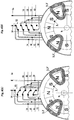
- Fig. 8 indicates an example of the arrangement of coils and magnets for three phases in the case where axial gap type coils are lap wound.
- the coil can be configured as a three-phase alternating current rotating machine (permanent magnet type rotating machine), or can be configured as a DC rotating machine by adding a commutator.
- Each coil 3, 3' of the U-phase coil 11, the V-phase coil 12, and the W-phase coil 13 is annually arranged in the circumferential direction on the front side, for example, in order at intervals of 120° in an electrical angle (in the case of the present embodiment, 40° in a mechanical angle).
- three-phase coils 3, 3' of the U-phase coil 11, the V-phase coil 12, and the W-phase coil 13 are annularly arranged on the back side in the circumferential direction in order by shifting 60° in an electrical angle (20° in the case of the mechanical angle in the present embodiment) from the coils 11, 12, and 13 of the respective phases on the front side. That is, by lap-winding the coils of Fig. 7 on the front and back, the number of coils is increased.
- the coils 11, 12, 13 of the respective phases on the front side and the coils 11, 12, 13 of the respective phases on the back side may simply be disposed in an overlapping manner, but as illustrated in Fig. 8(E) , portions protruding out of a space between the opposing magnets 6 (referred to as out-of-flux passing region) are bent in opposite directions, and as illustrated in Fig. 8(C) , the flux passing regions of the front side coil and the back side coil are disposed to be shifted in the circumferential direction so as not to overlap each other.
- the coil thickness can be halved (a thickness H for one coil) in the coil region occupied by a space between the magnets 6, that is, in the flux passing region.
- the coil is easily braided since the coil is a braided wire.
- the coils may be single-wound coils, double-wound coils, single-lap wound coils, or double-lap wound coils.
- Fig. 9 illustrates an example of a single axial type permanent magnet type rotating machine using the above-described coil as a stator coil.
- the coils 3, 3' of the present embodiment are disposed in a gap portion between a pair of the opposingly disposed magnets 6 such that a surface on the edge side of the electric wire 1 for winding opposes the magnets 6.
- the magnet 6 is held by the disk-shaped yoke 7 fixed to the rotor shaft 9 via the magnetic or nonmagnetic magnet holder 8, but it is not particularly limited thereto.
- a rotating machine sandwiches the coils 3, 3' by an NS magnetic circuit from both sides
- one side may be a magnetic yoke (not illustrated) instead of the magnet 6.
- Reference sign 16 in the drawing denotes a rotor magnetic body.
- the coils 3, 3' are configured as a stator coil in this embodiment, but it can also be configured as a rotor coil depending on the case.
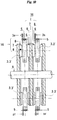
- Fig. 10 indicates an example of a double axial type permanent magnet type rotating machine using two sets of the above-described coils 3, 3' as stator coils.
- the permanent magnets 6 are disposed on both the front and back sides of the central yoke 7, and two pairs of magnetic circuits are formed with the permanent magnets 6 disposed opposite to each other on the outer side in the axial direction.
- a magnet holder denoted by reference sign 8 may be a magnetic body or a nonmagnetic body, but preferably a magnetic body.
- the thickness of a holder is desirably 1/2 or less of the thickness of the magnet.
- reference sign 16 in the drawing denotes a rotor magnetic body.
- the coils 3, 3' are disposed in a gap portion between a pair of the opposingly disposed magnets 6 such that a surface on the edge side of the electric wire 1 for winding opposes the magnets 6.
- the magnet 6 is held by the disk-shaped yoke 7 fixed to the rotor shaft 9 via the magnetic or nonmagnetic magnet holder 8, but it is not particularly limited thereto.
- the rotating machine sandwiches the coils 3, 3' by an NS magnetic circuit from both sides, one side may not be the magnet 6 and may be a magnetic yoke (not illustrated).
- the coils 3, 3' are configured as a stator coil in this embodiment, but it can also be configured as a rotor coil depending on the case.
- the electric wire 1 for winding of the present embodiment is a flat wire or a square wire composed of a flat braided wire and is excellent in flexibility, and therefore it can be easily twisted or bent in the middle of a wire. For this reason, it is possible to facilitate a work or to increase a wiring density by wiring in a straight line by twisting the flat wire by 90° at the time of wiring, coil connection, or wire connection. As a result, there is an advantage of being compact.
- the coils 3, 3' of the present embodiment can also be configured as a radial type stator coil of a permanent magnet type rotating machine.
- a single-wound coil or a double-wound coil wound in a rectangular shape or a tortoise shell shape as illustrated in Fig. 11(C) is disposed in a circumferential direction and lap wound or wave wound connected to form an annular shape, and disposed in a gap portion between an inner rotor magnetic body 14 and an outer rotor magnetic body 15.
- a three-phase coil as illustrated in Fig.
- coils in three phases are disposed so as to partially overlap in order.
- a surface on the edge side of the flat braided wire of the electric wire 1 for winding is disposed between the both magnets so as to face the magnet 6.
- the magnetic flux linkage between a pair of the magnets 6 is configured as a coil having a thickness corresponding to one coil width H (B dimension ⁇ number of turns).
- the inner rotor magnetic body 14 includes a ring-shaped yoke 7 fixed to the rotor shaft 9 and the magnet 6 held by the yoke 7 via a magnetic or nonmagnetic magnet holder 8. Further, the outer rotor magnetic body 15 includes the ring-shaped yoke 7 fixed to a rotor casing (not illustrated), and the magnet 6 held by the yoke 7 via the magnetic or nonmagnetic magnet holder 8.
- an electric wire for winding which is a flat wire or a square wire composed of a flat braided wire has excellent flexibility, it is easy to wind, and also an eddy current is suppressed, and a space factor also increases, and therefore the electrical resistance is reduced, and much more current flow to improve efficiency.
- the rotating machine increases ampere-turns per unit cross-sectional area, and small size, light weight, high output, and high efficiency can be achieved.
- an electric wire for winding formed with a flat braided wire can be easily wound around a small core and can be a coil with a high space factor, and therefore a coil and a motor can be compact, lightweight and have high output power and high efficiency.
- the electric wire for winding is applied to a permanent magnet type rotating machine
- the electric wire for winding can be applied to all rotating machines.
- the electric wire for winding can be used as an induction machine alone, and can be incorporated not only as an induction machine but also as a stator coil or a rotor coil of a synchronous machine.
- the example of a stator coil has been described, it is not particularly limited thereto, and it is obvious that the electric wire for winding can be used as a rotor coil. It is obvious that a radial type or axial type may be used as a coil.
- the electric wire for winding is applied to a coil for a rotating machine
- the electric wire for winding can be applied as a coil in other technical fields, for example, a cordless non-contact charger coil or a solenoid coil or the like.
- the electric wire 1 for winding according to the present invention is a flat wire or a square wire composed of a flat braided wire, it is excellent in flexibility in a direction in which the edge side (short side side) is not easily bent. Therefore, it is useful since it is easily processed in the case of winding as an edgewise coil.
- the coil shape is not limited to the above-described trapezoidal shape, and it can be easily finished as a coil of various shapes required, such as a coil wound in a rectangular, round, or saddle shape.
- a coreless coil of a single phase or multiple phases can also be formed by selectively connecting the winding start 3s and the winding end 3f of the coils 3, 3' with the winding start 3s or the winding end 3f of the other coils 3, 3'.
Landscapes
- Engineering & Computer Science (AREA)
- Power Engineering (AREA)
- Manufacturing & Machinery (AREA)
- Windings For Motors And Generators (AREA)
- Coils Of Transformers For General Uses (AREA)
- Insulated Conductors (AREA)
- Manufacture Of Motors, Generators (AREA)
Applications Claiming Priority (2)
| Application Number | Priority Date | Filing Date | Title |
|---|---|---|---|
| JP2016233028A JP6389501B2 (ja) | 2016-11-30 | 2016-11-30 | 回転機用コイル及び回転機 |
| PCT/JP2017/042953 WO2018101378A1 (ja) | 2016-11-30 | 2017-11-30 | 巻線用電線及びそれを用いた回転機用コイル並びに巻線用電線の製造方法 |
Publications (3)
| Publication Number | Publication Date |
|---|---|
| EP3550575A1 true EP3550575A1 (de) | 2019-10-09 |
| EP3550575A4 EP3550575A4 (de) | 2020-07-08 |
| EP3550575B1 EP3550575B1 (de) | 2026-03-25 |
Family
ID=62242269
Family Applications (1)
| Application Number | Title | Priority Date | Filing Date |
|---|---|---|---|
| EP17875577.3A Active EP3550575B1 (de) | 2016-11-30 | 2017-11-30 | Spule für rotierende maschine mit elektrischem draht zum wickeln |
Country Status (7)
| Country | Link |
|---|---|
| US (1) | US11128190B2 (de) |
| EP (1) | EP3550575B1 (de) |
| JP (1) | JP6389501B2 (de) |
| KR (1) | KR102228470B1 (de) |
| CN (1) | CN110024050B (de) |
| TW (1) | TWI713803B (de) |
| WO (1) | WO2018101378A1 (de) |
Cited By (2)
| Publication number | Priority date | Publication date | Assignee | Title |
|---|---|---|---|---|
| WO2021220037A1 (en) | 2020-04-30 | 2021-11-04 | Siscrener Global Company Limited | Stator core, stator, and power generation system having the same |
| GB2625658A (en) * | 2021-06-24 | 2024-06-26 | Eta Green Power Ltd | Stator for an electric machine |
Families Citing this family (12)
| Publication number | Priority date | Publication date | Assignee | Title |
|---|---|---|---|---|
| DE112018000592B4 (de) * | 2017-01-30 | 2025-03-27 | Kesatoshi Takeuchi | Kernlose elektrische Maschine und Spulenanordnung |
| JP2020048304A (ja) * | 2018-09-18 | 2020-03-26 | 公明 岩谷 | コアレスコイル並びにそれを用いた回転機 |
| GB2580918B (en) * | 2019-01-29 | 2021-07-07 | Saietta Group Ltd | Axial flux electrical machine |
| JP2021078242A (ja) * | 2019-11-08 | 2021-05-20 | 株式会社デンソー | 回転電機 |
| JP7868835B2 (ja) * | 2020-02-13 | 2026-06-02 | 有限会社 宮脇工房 | コイル及びコイルの製造方法 |
| US11750054B2 (en) * | 2020-05-18 | 2023-09-05 | Launchpoint Electric Propulsion Solutions, Inc. | Modulated litz wire construction for high power-density motors |
| TWI717308B (zh) * | 2020-08-26 | 2021-01-21 | 楊智傑 | 多層平面繞線式繞組結構及其製造方法 |
| JP2022041690A (ja) * | 2020-09-01 | 2022-03-11 | 有限会社 宮脇工房 | 電磁コイル |
| CN113257535A (zh) * | 2021-03-25 | 2021-08-13 | 深圳市科达嘉电子有限公司 | 一种编织线电感线圈和编织线大电流电感 |
| EP4070956A1 (de) * | 2021-04-07 | 2022-10-12 | Maxon International AG | Additiv gefertigte luftspaltwicklung für eine elektrische maschine |
| US11677303B2 (en) * | 2021-10-21 | 2023-06-13 | National Cheng Kung University | Motor and coreless stator coil winding unit thereof |
| TWI900109B (zh) * | 2024-07-04 | 2025-10-01 | 致茂電子股份有限公司 | 絞合式連接線 |
Family Cites Families (22)
| Publication number | Priority date | Publication date | Assignee | Title |
|---|---|---|---|---|
| JPS62234805A (ja) * | 1986-04-04 | 1987-10-15 | 日本ピラ−工業株式会社 | フラツトケ−ブル |
| DE4233898A1 (de) * | 1992-10-08 | 1994-04-14 | Bosch Gmbh Robert | Transformatorwicklung |
| JPH08126275A (ja) | 1994-10-25 | 1996-05-17 | Sawafuji Electric Co Ltd | コアレス回転機 |
| US5744896A (en) * | 1996-05-21 | 1998-04-28 | Visual Computing Systems Corp. | Interlocking segmented coil array |
| JPH10233128A (ja) * | 1997-02-19 | 1998-09-02 | Jiemitsukusu Kk | 高周波用ケーブル |
| JP3481890B2 (ja) | 1999-09-08 | 2003-12-22 | 東亜鉄網株式会社 | 圧縮成形物およびその製造方法 |
| US6333723B1 (en) * | 2000-12-05 | 2001-12-25 | Magneto-Inductive Systems Limited | Switchable transceiver antenna |
| JP2002208527A (ja) | 2001-01-12 | 2002-07-26 | Toko Inc | 漏れ磁束型電力変換トランス |
| JP2002358840A (ja) * | 2001-05-31 | 2002-12-13 | Totoku Electric Co Ltd | 高周波コイル用平編みリッツ線 |
| US7746025B2 (en) * | 2005-02-14 | 2010-06-29 | Lg Electronics Inc. | Variable speed motor |
| JP4904989B2 (ja) * | 2006-08-24 | 2012-03-28 | 株式会社日立製作所 | 回転電機,巻線機,回転電機システム,ハイブリッド自動車,燃料電池自動車、及び電気自動車 |
| FI120523B (fi) | 2007-03-02 | 2009-11-13 | Abb Oy | Menetelmä sähkökoneen käämivyyhden valmistamiseksi ja sähkökoneen käämitys |
| TW200849289A (en) | 2007-06-05 | 2008-12-16 | Shihlin Electric & Eng Corp | Shielding structure of a switcher |
| US8772636B2 (en) | 2008-06-25 | 2014-07-08 | Yazaki Corporation | Wire harness installation structure and wire harness-flattening band |
| JP5334504B2 (ja) * | 2008-09-08 | 2013-11-06 | 東京特殊電線株式会社 | エッジワイズコイル製造装置 |
| JP5234173B2 (ja) * | 2010-06-11 | 2013-07-10 | トヨタ自動車株式会社 | ステータ及びそれに使用される単位コイルの製造方法 |
| JP6095414B2 (ja) | 2013-02-27 | 2017-03-15 | 株式会社ミツバ | 平角線の巻線方法 |
| JP6049566B2 (ja) * | 2013-08-08 | 2016-12-21 | 日立オートモティブシステムズ株式会社 | 回転電機 |
| KR101593323B1 (ko) | 2013-09-18 | 2016-02-11 | 티디케이가부시기가이샤 | 코일 장치 |
| WO2015052964A1 (ja) * | 2013-10-08 | 2015-04-16 | 三菱電機株式会社 | 回転電機およびその製造方法 |
| JP6421484B2 (ja) | 2014-07-28 | 2018-11-14 | Tdk株式会社 | コイル部品、コイル部品複合体およびトランス、ならびに電源装置 |
| JP6113247B1 (ja) * | 2015-10-22 | 2017-04-12 | 三菱電機株式会社 | 回転電機の固定子 |
-
2016
- 2016-11-30 JP JP2016233028A patent/JP6389501B2/ja active Active
-
2017
- 2017-11-30 WO PCT/JP2017/042953 patent/WO2018101378A1/ja not_active Ceased
- 2017-11-30 CN CN201780073739.7A patent/CN110024050B/zh active Active
- 2017-11-30 KR KR1020197015024A patent/KR102228470B1/ko active Active
- 2017-11-30 TW TW106141848A patent/TWI713803B/zh active
- 2017-11-30 EP EP17875577.3A patent/EP3550575B1/de active Active
- 2017-11-30 US US16/463,264 patent/US11128190B2/en active Active
Cited By (4)
| Publication number | Priority date | Publication date | Assignee | Title |
|---|---|---|---|---|
| WO2021220037A1 (en) | 2020-04-30 | 2021-11-04 | Siscrener Global Company Limited | Stator core, stator, and power generation system having the same |
| EP4143950A4 (de) * | 2020-04-30 | 2024-05-22 | Siscrener Global Company Limited | Statorkern, stator und stromerzeugungssystem damit |
| GB2625658A (en) * | 2021-06-24 | 2024-06-26 | Eta Green Power Ltd | Stator for an electric machine |
| GB2625658B (en) * | 2021-06-24 | 2025-05-07 | Eta Green Power Ltd | Stator for an electric machine |
Also Published As
| Publication number | Publication date |
|---|---|
| US20190296596A1 (en) | 2019-09-26 |
| CN110024050A (zh) | 2019-07-16 |
| JP2018093577A (ja) | 2018-06-14 |
| EP3550575B1 (de) | 2026-03-25 |
| KR102228470B1 (ko) | 2021-03-15 |
| CN110024050B (zh) | 2021-01-01 |
| WO2018101378A1 (ja) | 2018-06-07 |
| KR20190067906A (ko) | 2019-06-17 |
| JP6389501B2 (ja) | 2018-09-12 |
| TWI713803B (zh) | 2020-12-21 |
| TW201832251A (zh) | 2018-09-01 |
| US11128190B2 (en) | 2021-09-21 |
| EP3550575A4 (de) | 2020-07-08 |
Similar Documents
| Publication | Publication Date | Title |
|---|---|---|
| US11128190B2 (en) | Rotary machine coil using a winding electric wire | |
| US9425664B2 (en) | Composite stator for electromechanical power conversion | |
| US6806612B2 (en) | Armature coil for slotless rotary electric machinery | |
| US10574110B2 (en) | Lightweight and efficient electrical machine and method of manufacture | |
| US9077216B2 (en) | Stator for rotating electrical machine | |
| US6894418B2 (en) | Nested stator coils for permanent magnet machines | |
| JP5576246B2 (ja) | アキシャルギャップ型ブラシレスモータ | |
| KR101413941B1 (ko) | 초전도 회전전기 및 초전도 회전전기용 고정자 | |
| JP4421018B2 (ja) | スロットレス固定子巻線およびその製造方法 | |
| KR102757596B1 (ko) | 전자 기계 구성 요소의 권선 직조 방법 | |
| US11063488B2 (en) | Stator for electric rotating machine | |
| EP2695284B1 (de) | Kompakter mehrphasiger wellenwicklung für einer elektrischen maschine mit hoher spezifische drehmomente | |
| TW201521330A (zh) | 集中繞組馬達 | |
| JP2009171839A (ja) | スロットレスモータのための固定子巻線 | |
| US9768652B2 (en) | Superconducting field pole | |
| US11967870B2 (en) | Toroidal polyphase electric machine | |
| US20100125999A1 (en) | Method of forming coil assembly for stator | |
| US20190280550A1 (en) | Laminated stack motor | |
| CN110556934A (zh) | 定子组件和具有其的电机 | |
| JP2020048304A (ja) | コアレスコイル並びにそれを用いた回転機 | |
| JP5972154B2 (ja) | 回転電機 | |
| TW201330456A (zh) | 變頻電動機裝置 | |
| US9941759B2 (en) | Stator winding arrangement of superconducting rotating machine | |
| CN220325368U (zh) | 一种发电机散嵌型绕组结构 | |
| JP2025132246A (ja) | モータ及びモータの製造方法 |
Legal Events
| Date | Code | Title | Description |
|---|---|---|---|
| STAA | Information on the status of an ep patent application or granted ep patent |
Free format text: STATUS: THE INTERNATIONAL PUBLICATION HAS BEEN MADE |
|
| PUAI | Public reference made under article 153(3) epc to a published international application that has entered the european phase |
Free format text: ORIGINAL CODE: 0009012 |
|
| STAA | Information on the status of an ep patent application or granted ep patent |
Free format text: STATUS: REQUEST FOR EXAMINATION WAS MADE |
|
| 17P | Request for examination filed |
Effective date: 20190618 |
|
| AK | Designated contracting states |
Kind code of ref document: A1 Designated state(s): AL AT BE BG CH CY CZ DE DK EE ES FI FR GB GR HR HU IE IS IT LI LT LU LV MC MK MT NL NO PL PT RO RS SE SI SK SM TR |
|
| AX | Request for extension of the european patent |
Extension state: BA ME |
|
| DAV | Request for validation of the european patent (deleted) | ||
| DAX | Request for extension of the european patent (deleted) | ||
| A4 | Supplementary search report drawn up and despatched |
Effective date: 20200608 |
|
| RIC1 | Information provided on ipc code assigned before grant |
Ipc: H02K 15/04 20060101ALI20200602BHEP Ipc: H02K 3/04 20060101ALI20200602BHEP Ipc: H01B 7/00 20060101AFI20200602BHEP Ipc: H02K 21/24 20060101ALN20200602BHEP Ipc: H01F 27/28 20060101ALI20200602BHEP Ipc: H01F 5/00 20060101ALI20200602BHEP |
|
| STAA | Information on the status of an ep patent application or granted ep patent |
Free format text: STATUS: EXAMINATION IS IN PROGRESS |
|
| 17Q | First examination report despatched |
Effective date: 20210503 |
|
| RAP1 | Party data changed (applicant data changed or rights of an application transferred) |
Owner name: O.T.I. CO., LTD. |
|
| RIN1 | Information on inventor provided before grant (corrected) |
Inventor name: O.T.I. CO., LTD. |
|
| GRAP | Despatch of communication of intention to grant a patent |
Free format text: ORIGINAL CODE: EPIDOSNIGR1 |
|
| STAA | Information on the status of an ep patent application or granted ep patent |
Free format text: STATUS: GRANT OF PATENT IS INTENDED |
|
| RIC1 | Information provided on ipc code assigned before grant |
Ipc: H01B 7/00 20060101AFI20250925BHEP Ipc: H01F 5/00 20060101ALI20250925BHEP Ipc: H01F 27/28 20060101ALI20250925BHEP Ipc: H02K 3/04 20060101ALI20250925BHEP Ipc: H02K 15/04 20060101ALI20250925BHEP Ipc: H02K 3/14 20060101ALI20250925BHEP Ipc: H02K 21/24 20060101ALN20250925BHEP |
|
| INTG | Intention to grant announced |
Effective date: 20251015 |
|
| GRAS | Grant fee paid |
Free format text: ORIGINAL CODE: EPIDOSNIGR3 |
|
| GRAA | (expected) grant |
Free format text: ORIGINAL CODE: 0009210 |
|
| STAA | Information on the status of an ep patent application or granted ep patent |
Free format text: STATUS: THE PATENT HAS BEEN GRANTED |
|
| AK | Designated contracting states |
Kind code of ref document: B1 Designated state(s): AL AT BE BG CH CY CZ DE DK EE ES FI FR GB GR HR HU IE IS IT LI LT LU LV MC MK MT NL NO PL PT RO RS SE SI SK SM TR |
|
| REG | Reference to a national code |
Ref country code: CH Ref legal event code: F10 Free format text: ST27 STATUS EVENT CODE: U-0-0-F10-F00 (AS PROVIDED BY THE NATIONAL OFFICE) Effective date: 20260325 Ref country code: GB Ref legal event code: FG4D |
|
| RIN1 | Information on inventor provided before grant (corrected) |
Inventor name: IWAYA, KIMIAKI Inventor name: KAKETA, YUKI |
|
| REG | Reference to a national code |
Ref country code: DE Ref legal event code: R096 Ref document number: 602017094501 Country of ref document: DE |
|
| REG | Reference to a national code |
Ref country code: IE Ref legal event code: FG4D |
|
| PG25 | Lapsed in a contracting state [announced via postgrant information from national office to epo] |
Ref country code: RS Free format text: LAPSE BECAUSE OF FAILURE TO SUBMIT A TRANSLATION OF THE DESCRIPTION OR TO PAY THE FEE WITHIN THE PRESCRIBED TIME-LIMIT Effective date: 20260625 |
|
| PG25 | Lapsed in a contracting state [announced via postgrant information from national office to epo] |
Ref country code: GR Free format text: LAPSE BECAUSE OF FAILURE TO SUBMIT A TRANSLATION OF THE DESCRIPTION OR TO PAY THE FEE WITHIN THE PRESCRIBED TIME-LIMIT Effective date: 20260626 |
|
| REG | Reference to a national code |
Ref country code: LT Ref legal event code: MG9D |
|
| PG25 | Lapsed in a contracting state [announced via postgrant information from national office to epo] |
Ref country code: LT Free format text: LAPSE BECAUSE OF FAILURE TO SUBMIT A TRANSLATION OF THE DESCRIPTION OR TO PAY THE FEE WITHIN THE PRESCRIBED TIME-LIMIT Effective date: 20260325 |
|
| PG25 | Lapsed in a contracting state [announced via postgrant information from national office to epo] |
Ref country code: NO Free format text: LAPSE BECAUSE OF FAILURE TO SUBMIT A TRANSLATION OF THE DESCRIPTION OR TO PAY THE FEE WITHIN THE PRESCRIBED TIME-LIMIT Effective date: 20260625 |
|
| PG25 | Lapsed in a contracting state [announced via postgrant information from national office to epo] |
Ref country code: FI Free format text: LAPSE BECAUSE OF FAILURE TO SUBMIT A TRANSLATION OF THE DESCRIPTION OR TO PAY THE FEE WITHIN THE PRESCRIBED TIME-LIMIT Effective date: 20260325 Ref country code: SE Free format text: LAPSE BECAUSE OF FAILURE TO SUBMIT A TRANSLATION OF THE DESCRIPTION OR TO PAY THE FEE WITHIN THE PRESCRIBED TIME-LIMIT Effective date: 20260325 |
|
| PG25 | Lapsed in a contracting state [announced via postgrant information from national office to epo] |
Ref country code: HR Free format text: LAPSE BECAUSE OF FAILURE TO SUBMIT A TRANSLATION OF THE DESCRIPTION OR TO PAY THE FEE WITHIN THE PRESCRIBED TIME-LIMIT Effective date: 20260325 |
|
| PG25 | Lapsed in a contracting state [announced via postgrant information from national office to epo] |
Ref country code: LV Free format text: LAPSE BECAUSE OF FAILURE TO SUBMIT A TRANSLATION OF THE DESCRIPTION OR TO PAY THE FEE WITHIN THE PRESCRIBED TIME-LIMIT Effective date: 20260325 |
|
| PG25 | Lapsed in a contracting state [announced via postgrant information from national office to epo] |
Ref country code: BG Free format text: LAPSE BECAUSE OF FAILURE TO SUBMIT A TRANSLATION OF THE DESCRIPTION OR TO PAY THE FEE WITHIN THE PRESCRIBED TIME-LIMIT Effective date: 20260325 |
|
| REG | Reference to a national code |
Ref country code: NL Ref legal event code: MP Effective date: 20260325 |