EP3550631A1 - Knopfartige lithiumzellenabdichtungsstruktur und abdichtungsverfahren - Google Patents
Knopfartige lithiumzellenabdichtungsstruktur und abdichtungsverfahren Download PDFInfo
- Publication number
- EP3550631A1 EP3550631A1 EP17908101.3A EP17908101A EP3550631A1 EP 3550631 A1 EP3550631 A1 EP 3550631A1 EP 17908101 A EP17908101 A EP 17908101A EP 3550631 A1 EP3550631 A1 EP 3550631A1
- Authority
- EP
- European Patent Office
- Prior art keywords
- sealing
- overlapping
- cell
- sealing portion
- overlapping portion
- Prior art date
- Legal status (The legal status is an assumption and is not a legal conclusion. Google has not performed a legal analysis and makes no representation as to the accuracy of the status listed.)
- Pending
Links
Images
Classifications
-
- H—ELECTRICITY
- H01—ELECTRIC ELEMENTS
- H01M—PROCESSES OR MEANS, e.g. BATTERIES, FOR THE DIRECT CONVERSION OF CHEMICAL ENERGY INTO ELECTRICAL ENERGY
- H01M50/00—Constructional details or processes of manufacture of the non-active parts of electrochemical cells other than fuel cells, e.g. hybrid cells
- H01M50/10—Primary casings; Jackets or wrappings
- H01M50/102—Primary casings; Jackets or wrappings characterised by their shape or physical structure
- H01M50/109—Primary casings; Jackets or wrappings characterised by their shape or physical structure of button or coin shape
-
- H—ELECTRICITY
- H01—ELECTRIC ELEMENTS
- H01M—PROCESSES OR MEANS, e.g. BATTERIES, FOR THE DIRECT CONVERSION OF CHEMICAL ENERGY INTO ELECTRICAL ENERGY
- H01M50/00—Constructional details or processes of manufacture of the non-active parts of electrochemical cells other than fuel cells, e.g. hybrid cells
- H01M50/10—Primary casings; Jackets or wrappings
- H01M50/183—Sealing members
- H01M50/184—Sealing members characterised by their shape or structure
-
- H—ELECTRICITY
- H01—ELECTRIC ELEMENTS
- H01M—PROCESSES OR MEANS, e.g. BATTERIES, FOR THE DIRECT CONVERSION OF CHEMICAL ENERGY INTO ELECTRICAL ENERGY
- H01M10/00—Secondary cells; Manufacture thereof
- H01M10/04—Construction or manufacture in general
- H01M10/0422—Cells or battery with cylindrical casing
- H01M10/0427—Button cells
-
- H—ELECTRICITY
- H01—ELECTRIC ELEMENTS
- H01M—PROCESSES OR MEANS, e.g. BATTERIES, FOR THE DIRECT CONVERSION OF CHEMICAL ENERGY INTO ELECTRICAL ENERGY
- H01M10/00—Secondary cells; Manufacture thereof
- H01M10/05—Accumulators with non-aqueous electrolyte
- H01M10/052—Li-accumulators
-
- H—ELECTRICITY
- H01—ELECTRIC ELEMENTS
- H01M—PROCESSES OR MEANS, e.g. BATTERIES, FOR THE DIRECT CONVERSION OF CHEMICAL ENERGY INTO ELECTRICAL ENERGY
- H01M10/00—Secondary cells; Manufacture thereof
- H01M10/05—Accumulators with non-aqueous electrolyte
- H01M10/052—Li-accumulators
- H01M10/0525—Rocking-chair batteries, i.e. batteries with lithium insertion or intercalation in both electrodes; Lithium-ion batteries
-
- H—ELECTRICITY
- H01—ELECTRIC ELEMENTS
- H01M—PROCESSES OR MEANS, e.g. BATTERIES, FOR THE DIRECT CONVERSION OF CHEMICAL ENERGY INTO ELECTRICAL ENERGY
- H01M10/00—Secondary cells; Manufacture thereof
- H01M10/05—Accumulators with non-aqueous electrolyte
- H01M10/058—Construction or manufacture
- H01M10/0587—Construction or manufacture of accumulators having only wound construction elements, i.e. wound positive electrodes, wound negative electrodes and wound separators
-
- H—ELECTRICITY
- H01—ELECTRIC ELEMENTS
- H01M—PROCESSES OR MEANS, e.g. BATTERIES, FOR THE DIRECT CONVERSION OF CHEMICAL ENERGY INTO ELECTRICAL ENERGY
- H01M10/00—Secondary cells; Manufacture thereof
- H01M10/42—Methods or arrangements for servicing or maintenance of secondary cells or secondary half-cells
-
- H—ELECTRICITY
- H01—ELECTRIC ELEMENTS
- H01M—PROCESSES OR MEANS, e.g. BATTERIES, FOR THE DIRECT CONVERSION OF CHEMICAL ENERGY INTO ELECTRICAL ENERGY
- H01M50/00—Constructional details or processes of manufacture of the non-active parts of electrochemical cells other than fuel cells, e.g. hybrid cells
- H01M50/10—Primary casings; Jackets or wrappings
- H01M50/147—Lids or covers
- H01M50/148—Lids or covers characterised by their shape
- H01M50/153—Lids or covers characterised by their shape for button or coin cells
-
- H—ELECTRICITY
- H01—ELECTRIC ELEMENTS
- H01M—PROCESSES OR MEANS, e.g. BATTERIES, FOR THE DIRECT CONVERSION OF CHEMICAL ENERGY INTO ELECTRICAL ENERGY
- H01M50/00—Constructional details or processes of manufacture of the non-active parts of electrochemical cells other than fuel cells, e.g. hybrid cells
- H01M50/10—Primary casings; Jackets or wrappings
- H01M50/147—Lids or covers
- H01M50/166—Lids or covers characterised by the methods of assembling casings with lids
-
- H—ELECTRICITY
- H01—ELECTRIC ELEMENTS
- H01M—PROCESSES OR MEANS, e.g. BATTERIES, FOR THE DIRECT CONVERSION OF CHEMICAL ENERGY INTO ELECTRICAL ENERGY
- H01M50/00—Constructional details or processes of manufacture of the non-active parts of electrochemical cells other than fuel cells, e.g. hybrid cells
- H01M50/10—Primary casings; Jackets or wrappings
- H01M50/147—Lids or covers
- H01M50/166—Lids or covers characterised by the methods of assembling casings with lids
- H01M50/171—Lids or covers characterised by the methods of assembling casings with lids using adhesives or sealing agents
-
- H—ELECTRICITY
- H01—ELECTRIC ELEMENTS
- H01M—PROCESSES OR MEANS, e.g. BATTERIES, FOR THE DIRECT CONVERSION OF CHEMICAL ENERGY INTO ELECTRICAL ENERGY
- H01M50/00—Constructional details or processes of manufacture of the non-active parts of electrochemical cells other than fuel cells, e.g. hybrid cells
- H01M50/10—Primary casings; Jackets or wrappings
- H01M50/183—Sealing members
- H01M50/186—Sealing members characterised by the disposition of the sealing members
- H01M50/188—Sealing members characterised by the disposition of the sealing members the sealing members being arranged between the lid and terminal
-
- H—ELECTRICITY
- H01—ELECTRIC ELEMENTS
- H01M—PROCESSES OR MEANS, e.g. BATTERIES, FOR THE DIRECT CONVERSION OF CHEMICAL ENERGY INTO ELECTRICAL ENERGY
- H01M50/00—Constructional details or processes of manufacture of the non-active parts of electrochemical cells other than fuel cells, e.g. hybrid cells
- H01M50/10—Primary casings; Jackets or wrappings
- H01M50/183—Sealing members
- H01M50/19—Sealing members characterised by the material
- H01M50/197—Sealing members characterised by the material having a layered structure
-
- H—ELECTRICITY
- H01—ELECTRIC ELEMENTS
- H01M—PROCESSES OR MEANS, e.g. BATTERIES, FOR THE DIRECT CONVERSION OF CHEMICAL ENERGY INTO ELECTRICAL ENERGY
- H01M6/00—Primary cells; Manufacture thereof
- H01M6/02—Details
-
- H—ELECTRICITY
- H01—ELECTRIC ELEMENTS
- H01M—PROCESSES OR MEANS, e.g. BATTERIES, FOR THE DIRECT CONVERSION OF CHEMICAL ENERGY INTO ELECTRICAL ENERGY
- H01M6/00—Primary cells; Manufacture thereof
- H01M6/14—Cells with non-aqueous electrolyte
-
- Y—GENERAL TAGGING OF NEW TECHNOLOGICAL DEVELOPMENTS; GENERAL TAGGING OF CROSS-SECTIONAL TECHNOLOGIES SPANNING OVER SEVERAL SECTIONS OF THE IPC; TECHNICAL SUBJECTS COVERED BY FORMER USPC CROSS-REFERENCE ART COLLECTIONS [XRACs] AND DIGESTS
- Y02—TECHNOLOGIES OR APPLICATIONS FOR MITIGATION OR ADAPTATION AGAINST CLIMATE CHANGE
- Y02E—REDUCTION OF GREENHOUSE GAS [GHG] EMISSIONS, RELATED TO ENERGY GENERATION, TRANSMISSION OR DISTRIBUTION
- Y02E60/00—Enabling technologies; Technologies with a potential or indirect contribution to GHG emissions mitigation
- Y02E60/10—Energy storage using batteries
-
- Y—GENERAL TAGGING OF NEW TECHNOLOGICAL DEVELOPMENTS; GENERAL TAGGING OF CROSS-SECTIONAL TECHNOLOGIES SPANNING OVER SEVERAL SECTIONS OF THE IPC; TECHNICAL SUBJECTS COVERED BY FORMER USPC CROSS-REFERENCE ART COLLECTIONS [XRACs] AND DIGESTS
- Y02—TECHNOLOGIES OR APPLICATIONS FOR MITIGATION OR ADAPTATION AGAINST CLIMATE CHANGE
- Y02P—CLIMATE CHANGE MITIGATION TECHNOLOGIES IN THE PRODUCTION OR PROCESSING OF GOODS
- Y02P70/00—Climate change mitigation technologies in the production process for final industrial or consumer products
- Y02P70/50—Manufacturing or production processes characterised by the final manufactured product
Definitions
- the present disclosure relates to techniques of a button-type lithium cell and, in particular, to a structure and method for sealing the button-type lithium cell.
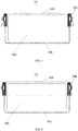
- FIG. 1 it is a sectional view of a conventional button-type lithium cell 10 before the cell is sealed.
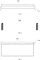
- the conventional button-type lithium cell 10 includes: a cell cover 100 (as illustrated in FIG. 3 ), a sealing ring 200 (as illustrated in FIG. 4 ), a cell casing 300 (as illustrated in FIG. 5 ) and a jelly roll 400.
- the conventional button-type lithium cell 10 is assembled as follows: firstly, the sealing ring 200 is nested in the cell casing 300; secondly, a cathode of the jelly roll 400 is welded to the cell casing 300 and an anode of the jelly roll 400 is welded to the cell cover 100; thirdly, the jelly roll 400 is placed into the cell casing 300 and the cell cover 100 is closed; finally, a special-purpose device is employed to seal the cell cover 100 (as illustrated in FIG. 2 ).
- a circular arc groove 310 of the cell casing 300 having a radius of 0.35 mm is formed 0.7 mm away from an opened end of the cell casing 300 and a circular arc groove 110 of the cell cover 100 having a radius of 0.5 mm is formed 1.3 mm away from the opened end of the cell cover 100. Because the circular arc groove 310 of the cell casing 300 and the circular arc groove 110 of the cell cover 100 both have so small a size that machining accuracy is difficult to guarantee, especially when the special-purpose device is rotated to seal the cell cover 100 (as illustrated in FIG. 2 ).
- the cell cover 100 swings in a rotation sealing process and the circular arc groove 310 of the cell casing 300 has too small a size to cut into the sealing ring 200 like a cutter, so the sealing ring 200 is easily damaged and broken to result in the liquid leakage of the cell, so that the button-type lithium cell 10 is directly scrapped.
- the present disclosure provides a structure and method for sealing the button-type lithium cell so as to prevent a sealing ring from being damaged and broken in a sealing process and avoid the liquid leakage of the cell, thereby improving overall sealing performance of the cell.
- a structure for sealing a button-type lithium cell includes: a cell cover, a sealing ring and a cell casing.
- the cell cover includes an overlapping structure, the overlapping structure includes a first overlapping portion, a second overlapping portion and a third overlapping portion which are connected in sequence, and the third overlapping portion includes a locking portion and a sealing portion, where the first overlapping portion is a cylindrical side structure, the second overlapping portion is a conical side structure, the locking portion is a cylindrical side structure and the sealing portion is a conical side structure.
- the cell casing includes a sealing structure, and the sealing structure includes a first sealing portion, a second sealing portion, a third sealing portion and a fourth sealing portion which are connected in sequence, where the first sealing portion and the third sealing portion are both conical side structures and the second sealing portion and the fourth sealing portion are both cylindrical side structures.
- the first overlapping portion abuts against the fourth sealing portion through the sealing ring
- the second overlapping portion abuts against the third sealing portion through the sealing ring
- the locking portion of the third overlapping portion abuts against the second sealing portion through the sealing ring
- the sealing portion of the third overlapping portion abuts against the first sealing portion through the sealing ring.
- the sealing structure further includes a jelly roll, and the jelly roll is received in a sealed chamber formed by the cell cover and the cell casing.
- the cell cover is a hollow cylindrical structure having a first opened end and a second closed end.
- the cell casing is a hollow cylindrical structure having a first opened end and a second closed end.
- the first overlapping portion, the second overlapping portion and the third overlapping portion are formed integrally.
- first sealing portion, the second sealing portion, the third sealing portion and the fourth sealing portion are formed integrally.
- a method for sealing a button-type lithium cell by use of the structure above, includes the steps described below.
- the sealing ring is nested in the cell casing.
- the cell cover is covered onto the cell casing so that the first overlapping portion abuts against the fourth sealing portion through the sealing ring, the second overlapping portion abuts against the third sealing portion through the sealing ring, the locking portion of the third overlapping portion abuts against the second sealing portion through the sealing ring.
- the sealing portion of the third overlapping portion is hemmed and shrunk so that the sealing portion of the third overlapping portion abuts against the first sealing portion through the sealing ring.
- the structure and method for sealing the button-type lithium cell provided in the present disclosure can prevent the sealing ring from being damaged and broken in the sealing process and avoid the liquid leakage of the cell, thereby improving the overall sealing performance of the cell.
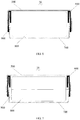
- a structure for sealing the button-type lithium cell 20 includes: a cell cover 500, a sealing ring 600 and a cell casing 700.
- the cell cover 500 and the cell casing 700 are both hollow cylindrical structures having a first opened end and a second closed end.
- the structure 20 further includes a jelly roll 800. The jelly roll 800 is received in a sealed chamber formed by the cell cover 500 and the cell casing 700.
- the cell cover 500 includes an overlapping structure 510.
- the overlapping structure 510 includes a first overlapping portion 521, a second overlapping portion 522 and a third overlapping portion 523 which are connected in sequence.
- the third overlapping portion 523 includes a locking portion 523a and a sealing portion 523b.
- the first overlapping portion 521 is a cylindrical side structure
- the second overlapping portion 522 is a conical side structure
- the locking portion 523a is a cylindrical side structure
- the sealing portion 523b is a conical side structure.
- the cylindrical side structure is a hollow cylindrical structure and the conical side structure is a hollow and truncated conical structure with two opened ends.
- the first overlapping portion 521 is a hollow cylindrical structure with one opened end; the second overlapping portion 522 is a hollow and truncated conical structure with two opened ends; the locking portion 523a is a hollow cylindrical structure with two opened ends; and the sealing portion 523b is a hollow truncated conical structure with two opened ends.
- the cell casing 700 includes a sealing structure 710.
- the sealing structure 710 includes a first sealing portion 721, a second sealing portion 722, a third sealing portion 723 and a fourth sealing portion 724 which are connected in sequence.
- the first sealing portion 721 and the third sealing portion 723 are both conical side structures, and the second sealing portion 722 and the fourth sealing portion 724 are both cylindrical side structures.
- the first overlapping portion 521 abuts against the fourth sealing portion 724through the sealing ring 600.
- the second overlapping portion 522 abuts against the third sealing portion 723 through the sealing ring 600.
- the locking portion 523a of the third overlapping portion 523 abuts against the second sealing portion 722 through the sealing ring 600.
- the sealing portion 523b of the third overlapping portion 523 abuts against the first sealing portion 721 through the sealing ring 600.
- the overlapping structure 510 includes the first overlapping portion 521, the second overlapping portion 522 and the third overlapping portion 523 which are connected in sequence.
- the third overlapping portion 523 includes the locking portion 523a and the sealing portion 523b.
- the sealing structure 710 includes the first sealing portion 721, the second sealing portion 722, the third sealing portion 723 and the fourth sealing portion 724 which are connected in sequence.
- the first overlapping portion 521 abuts against the fourth sealing portion 724
- the second overlapping portion 522 abuts against the third sealing portion 723
- the locking portion 523a of the third overlapping portion 523 abuts against the second sealing portion 722
- the sealing portion 523b of the third overlapping portion 523 abuts against the first sealing portion 721, so as to press the sealing ring 600 tightly between the overlapping structure 510 and the sealing structure 710 and achieve sealing.
- a structure 630 of the sealing ring 600 includes a first sealing surface, a second sealing surface, a third sealing surface and a fourth sealing surface which are connected in sequence.
- the first sealing surface is pressed between the first overlapping portion 521 and the fourth sealing portion 724.
- the second sealing surface is squeezed between the second overlapping portion 522 and the third sealing portion 722.
- the third sealing surface is squeezed between the locking portion 523a of the third overlapping portion 523 and the second sealing portion 723.
- the fourth sealing surface is squeezed between the sealing portion 523b of the third overlapping portion 523 and the first sealing portion 721.
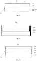
- the second overlapping portion 522 and the sealing portion 523b form conical side sealing structures in reverse directions (as illustrated in FIG. 8 ).
- the first sealing portion 721 and the third sealing portion 723 also form the conical side sealing structures in reverse directions (as illustrated in FIG. 10 ).
- the conical side sealing structures in reverse directions have a more effective fastening function and prevent the sealing portion 523b from swinging when the sealing portion 523b is hemmed and shrunk for sealing by rotation of the cell cover.
- the conical side sealing structures in reverse directions deform the structure 630 of the sealing ring 600 by squeezing the structure 630 of the sealing ring 600, thereby achieving more effective sealing and increasing fastening stability of the cell casing 700, the sealing ring 600 and the cell cover 500.
- An overlapping structure 520 includes the first overlapping portion 521, the second overlapping portion 522 and the third overlapping portion 523 which are connected in sequence.
- the first overlapping portion 521, the second overlapping portion 522 and the third overlapping portion 523 form a rugged structure.
- a sealing structure 720 includes the first sealing portion 721, a second sealing portion 722, a third sealing portion 723 and a fourth sealing portion 724 which are connected sequence.
- the first sealing portion 721, the second sealing portion 722, the third sealing portion 723 and the fourth sealing portion 724 also form a rugged structure.
- the structure 630 of the sealing ring 600 is squeezed tightly between the overlapping structure 520 and the sealing structure 720.
- the structure 630 of the sealing ring 600 has a larger contact area with the cell cover 500 and the cell casing 700, resulting in a larger sealing area and better sealing performance.
- the sealing ring 600 improves the air tightness between the overlapping structure 520 and the sealing structure 720 to prevent the occurrence of the liquid leakage of the cell.
- a protruding structure is trapped in a groove structure to form a latching structure, so that the cell cover 500 is tightly fastened in the cell casing 700 and not easily detached, thereby improving the fastening stability.
- the third overlapping portion 523 includes the sealing portion 523b.
- the sealing portion 523b of the third overlapping portion 523 is hemmed and shrunk by a special-purpose device (as illustrated in FIG. 7 ) to achieve the sealing and further improve the fastening stability.
- the first overlapping portion 521 has a cylindrical shape
- the second overlapping portion 522 has a truncated cone shape
- the locking portion 523a has a cylindrical shape
- the sealing portion 523b has a truncated cone shape.
- such a structure has the overlapping structure 520 which does not produce a sharp cutter-shaped protruding structure and similarly, the sealing structure 720 does not produce the sharp cutter-shaped protruding structure so that the structure 630 of the sealing ring 600 will not be damaged and broken.
- the sealing portion 523b of the third overlapping portion 523 is hemmed and shrunk by a special-purpose device to achieve fastening.
- the sealing ring 600 includes a protruding end 620 protruding from a connection point of the overlapping structure 520 and the sealing structure 720 (as illustrated in FIG. 7 ), so as to more effectively prevent the cell cover 500 and the cell casing 700 from contacting with each other to result in a short circuit.
- the sealing ring 600 further includes a pre-positioned ring structure 610.
- the pre-positioned ring structure 610 is elastically nested in one end surface of the fourth sealing portion 724.
- the sealing ring 600 is pre-fastened by providing the pre-positioned ring structure 610. That is, the sealing ring 600 is nested in the one end surface of the fourth sealing portion 724 of the cell casing 700 with the pre-positioned ring structure 610, thereby preventing the sealing ring 600 from being detached and preparing for the subsequent stable sealing when the cell cover 500 is covered onto the cell casing 700.
- the present embodiment further provides a method for sealing the button-type lithium cell by use of the above structure 20.
- the method includes the steps described below.
- the sealing ring 600 is nested in the cell casing 700.
- the cell cover 500 is covered onto the cell casing 700 so that the first overlapping portion 521 abuts against the fourth sealing portion 724 through the sealing ring 600, the second overlapping portion 522 abuts against the third sealing portion 723through the sealing ring 600, the locking portion 523a of the third overlapping portion 523 abuts against the second sealing portion 722 through the sealing ring 600.
- the sealing portion 523b of the third overlapping portion 523 is hemmed and shrunk so that the sealing portion 523b of the third overlapping portion 523 abuts against the first sealing portion 721 through the sealing ring 600.
- the cell cover 500, the sealing ring 600 and the cell casing 700 are provided, and in particular, the overlapping structure 520 of the cell cover 500 and the sealing structure 720 of the cell casing 700 are optimized, so as to prevent the seal ring 600 from being damaged and broken in the sealing process and avoid the liquid leakage of the cell, thereby improving the overall sealing performance.
- the structure for sealing the button-type lithium cell provided by the present disclosure can prevent the sealing ring from being damaged and broken in the sealing process and avoid the liquid leakage of the cell, thereby improving the overall sealing performance.
Landscapes
- Chemical & Material Sciences (AREA)
- Chemical Kinetics & Catalysis (AREA)
- Electrochemistry (AREA)
- General Chemical & Material Sciences (AREA)
- Engineering & Computer Science (AREA)
- Manufacturing & Machinery (AREA)
- Materials Engineering (AREA)
- Sealing Battery Cases Or Jackets (AREA)
Applications Claiming Priority (2)
| Application Number | Priority Date | Filing Date | Title |
|---|---|---|---|
| CN201710470397.4A CN107425145B (zh) | 2017-06-20 | 2017-06-20 | 一种钮扣式锂电芯密封结构及密封方法 |
| PCT/CN2017/119680 WO2018233267A1 (zh) | 2017-06-20 | 2017-12-29 | 钮扣式锂电芯密封结构及密封方法 |
Publications (2)
| Publication Number | Publication Date |
|---|---|
| EP3550631A1 true EP3550631A1 (de) | 2019-10-09 |
| EP3550631A4 EP3550631A4 (de) | 2020-06-10 |
Family
ID=60427419
Family Applications (1)
| Application Number | Title | Priority Date | Filing Date |
|---|---|---|---|
| EP17908101.3A Pending EP3550631A4 (de) | 2017-06-20 | 2017-12-29 | Knopfartige lithiumzellenabdichtungsstruktur und abdichtungsverfahren |
Country Status (6)
| Country | Link |
|---|---|
| US (1) | US11201369B2 (de) |
| EP (1) | EP3550631A4 (de) |
| JP (1) | JP6734401B2 (de) |
| KR (1) | KR102191720B1 (de) |
| CN (1) | CN107425145B (de) |
| WO (1) | WO2018233267A1 (de) |
Cited By (3)
| Publication number | Priority date | Publication date | Assignee | Title |
|---|---|---|---|---|
| EP4087033A4 (de) * | 2020-07-14 | 2024-01-17 | LG Energy Solution, Ltd. | Sekundärbatterie vom knopftyp |
| EP4145597A4 (de) * | 2020-04-29 | 2024-08-21 | Samsung SDI Co., Ltd. | Wiederaufladbare batterie |
| EP4672448A1 (de) * | 2024-06-25 | 2025-12-31 | Samsung Sdi Co., Ltd. | Sekundärbatterie und verfahren zur herstellung davon |
Families Citing this family (31)
| Publication number | Priority date | Publication date | Assignee | Title |
|---|---|---|---|---|
| CN107425145B (zh) | 2017-06-20 | 2023-06-20 | 惠州亿纬锂能股份有限公司 | 一种钮扣式锂电芯密封结构及密封方法 |
| CN109449320B (zh) * | 2018-11-06 | 2021-01-26 | 河南省鹏辉电源有限公司 | 一种纽扣电池外壳结构、纽扣电池以及用电设备 |
| US11757154B2 (en) * | 2019-02-02 | 2023-09-12 | Guangdong Mic-power New Energy Co., Ltd. | Battery apparatus and electronic device |
| CN110311063A (zh) * | 2019-06-06 | 2019-10-08 | 金能电池(东莞)有限公司 | 一种多级密封多级防爆的电池封口结构 |
| CN110838593B (zh) * | 2019-12-13 | 2024-07-16 | 惠州亿纬锂能股份有限公司 | 叠片式豆式电池 |
| WO2021114324A1 (zh) * | 2019-12-13 | 2021-06-17 | 惠州亿纬锂能股份有限公司 | 卷绕式豆式电池 |
| WO2021114329A1 (zh) * | 2019-12-13 | 2021-06-17 | 惠州亿纬锂能股份有限公司 | 卷绕式豆式电池 |
| CN110797480B (zh) * | 2019-12-13 | 2025-01-03 | 惠州亿纬锂能股份有限公司 | 卷绕式豆式电池 |
| WO2021114323A1 (zh) * | 2019-12-13 | 2021-06-17 | 惠州亿纬锂能股份有限公司 | 卷绕式豆式电池 |
| CN111048702A (zh) * | 2019-12-31 | 2020-04-21 | 广东微电新能源有限公司 | 凸棱电池 |
| TWI900540B (zh) | 2020-03-11 | 2025-10-11 | 南韓商Lg新能源股份有限公司 | 鈕扣型二次電池 |
| CN111180617A (zh) * | 2020-03-16 | 2020-05-19 | 惠州亿纬锂能股份有限公司 | 一种二次锂离子豆式电池及其制作方法 |
| CN111211259A (zh) * | 2020-03-16 | 2020-05-29 | 惠州亿纬锂能股份有限公司 | 一种豆式电池及其制作方法 |
| CN111162209A (zh) * | 2020-03-16 | 2020-05-15 | 惠州亿纬锂能股份有限公司 | 一种二次锂离子豆式电池及其制作方法 |
| CN111162211A (zh) * | 2020-03-16 | 2020-05-15 | 惠州亿纬锂能股份有限公司 | 一种豆式电池及其制作方法 |
| US11641044B1 (en) * | 2020-04-14 | 2023-05-02 | Energizer Brands, Llc | Battery housing and systems and methods of making thereof |
| CN212303778U (zh) * | 2020-05-06 | 2021-01-05 | 广东微电新能源有限公司 | 纽扣电池或柱状电池 |
| KR102927430B1 (ko) * | 2020-05-29 | 2026-02-12 | 삼성에스디아이 주식회사 | 이차 전지 |
| CN112002835B (zh) * | 2020-06-09 | 2025-10-10 | 深圳市格瑞普电池有限公司 | 扣式锂离子电池及其制备方法 |
| KR20210158162A (ko) * | 2020-06-23 | 2021-12-30 | 삼성에스디아이 주식회사 | 이차 전지 |
| WO2022005232A1 (ko) * | 2020-07-01 | 2022-01-06 | 주식회사 엘지에너지솔루션 | 버튼형 이차전지 및 그의 제조방법 |
| KR20220003473A (ko) * | 2020-07-01 | 2022-01-10 | 주식회사 엘지에너지솔루션 | 버튼형 이차전지 및 그의 제조방법 |
| KR102918561B1 (ko) * | 2020-07-17 | 2026-01-27 | 주식회사 엘지에너지솔루션 | 버튼형 이차전지 및 그의 제조방법 |
| EP4120450A4 (de) * | 2020-07-29 | 2024-07-31 | LG Energy Solution, Ltd. | Knopfartige sekundärbatterie und verfahren zur herstellung davon |
| CN111834558B (zh) * | 2020-08-10 | 2024-05-07 | 惠州亿纬锂能股份有限公司 | 一种电子器件及其制作方法 |
| US12592438B2 (en) | 2020-08-10 | 2026-03-31 | Eve Energy Co., Ltd. | Electronic device and manufacturing method therefor |
| CN112331976B (zh) * | 2020-08-31 | 2023-09-01 | 宁德时代新能源科技股份有限公司 | 箱体、电池、用电设备及箱体的组装方法 |
| US20230045132A1 (en) * | 2020-09-16 | 2023-02-09 | Lg Energy Solution, Ltd. | Button-type secondary battery |
| EP4181280A4 (de) * | 2020-09-17 | 2024-04-24 | LG Energy Solution, Ltd. | Knopfartige sekundärbatterie |
| CN116034515A (zh) * | 2020-09-17 | 2023-04-28 | 株式会社Lg新能源 | 纽扣型二次电池 |
| KR102885312B1 (ko) * | 2020-09-21 | 2025-11-13 | 주식회사 엘지에너지솔루션 | 버튼형 이차전지 |
Family Cites Families (20)
| Publication number | Priority date | Publication date | Assignee | Title |
|---|---|---|---|---|
| US3839092A (en) * | 1973-04-02 | 1974-10-01 | Yardney International Corp | Electro-chemical, gasproof button cell |
| US5945230A (en) * | 1997-03-28 | 1999-08-31 | Rayovac Corporation | Toed-in anode can and electrochemical cell made therewith |
| JP3703667B2 (ja) * | 1998-12-24 | 2005-10-05 | 株式会社エスアイアイ・マイクロパーツ | 非水電解質二次電池 |
| US7576969B2 (en) * | 2003-12-03 | 2009-08-18 | Panasonic Corporation | Coin-shaped storage cell |
| JP2005191507A (ja) * | 2003-12-03 | 2005-07-14 | Matsushita Electric Ind Co Ltd | コイン形蓄電素子 |
| US7632605B2 (en) * | 2005-04-29 | 2009-12-15 | Eveready Battery Co., Inc. | Alkaline cell anode casing |
| DE102005058132A1 (de) | 2005-11-30 | 2007-06-06 | Varta Microbattery Gmbh | Galvanisches Element mit neuartigem Gehäuse |
| US20070224495A1 (en) * | 2006-03-22 | 2007-09-27 | Gibbons Daniel W | Zinc/air cell |
| DE102007009295A1 (de) * | 2007-02-16 | 2008-08-21 | Varta Microbattery Gmbh | Galvanisches Element mit hoher Kapazität |
| US20100047666A1 (en) * | 2008-08-25 | 2010-02-25 | Eveready Battery Company, Inc. | Electrochemical Cell with Shaped Catalytic Electrode Casing |
| DE102010012977A1 (de) * | 2010-03-22 | 2011-09-22 | Varta Microbattery Gmbh | Gegen Kurzschluss gesicherte Knopfzelle |
| DE102010033577A1 (de) * | 2010-08-03 | 2012-02-09 | Varta Microbattery Gmbh | Knopfzelle mit Wickelelektrode mit thermischer Sicherung |
| US9564654B2 (en) * | 2010-09-14 | 2017-02-07 | Zhuhai Zhi Li Battery Co. Ltd. | Rechargeable lithium ion button cell battery |
| CN103000832A (zh) * | 2012-12-18 | 2013-03-27 | 河南创力新能源科技有限公司 | 一种扣式电池密封圈及扣式电池 |
| EP2827398B1 (de) * | 2013-07-17 | 2016-02-24 | VARTA Microbattery GmbH | Metall-Luft-Knopfzellen und Verfahren zu ihrer Herstellung |
| CN106129274A (zh) * | 2016-07-15 | 2016-11-16 | 重庆市紫建电子有限公司 | 一种扣式锂离子电池 |
| CN107425145B (zh) * | 2017-06-20 | 2023-06-20 | 惠州亿纬锂能股份有限公司 | 一种钮扣式锂电芯密封结构及密封方法 |
| CN207038560U (zh) * | 2017-06-20 | 2018-02-23 | 惠州亿纬锂能股份有限公司 | 一种钮扣式锂电芯密封结构 |
| CN109449320B (zh) * | 2018-11-06 | 2021-01-26 | 河南省鹏辉电源有限公司 | 一种纽扣电池外壳结构、纽扣电池以及用电设备 |
| CN109585721A (zh) * | 2019-01-17 | 2019-04-05 | 潍坊裕元电子有限公司 | 一种扣式微型可充电锂电池结构组件 |
-
2017
- 2017-06-20 CN CN201710470397.4A patent/CN107425145B/zh active Active
- 2017-12-29 JP JP2018560757A patent/JP6734401B2/ja active Active
- 2017-12-29 US US16/303,032 patent/US11201369B2/en active Active
- 2017-12-29 EP EP17908101.3A patent/EP3550631A4/de active Pending
- 2017-12-29 WO PCT/CN2017/119680 patent/WO2018233267A1/zh not_active Ceased
- 2017-12-29 KR KR1020187033914A patent/KR102191720B1/ko active Active
Cited By (4)
| Publication number | Priority date | Publication date | Assignee | Title |
|---|---|---|---|---|
| EP4145597A4 (de) * | 2020-04-29 | 2024-08-21 | Samsung SDI Co., Ltd. | Wiederaufladbare batterie |
| US12506201B2 (en) | 2020-04-29 | 2025-12-23 | Samsung Sdi Co., Ltd. | Rechargeable battery |
| EP4087033A4 (de) * | 2020-07-14 | 2024-01-17 | LG Energy Solution, Ltd. | Sekundärbatterie vom knopftyp |
| EP4672448A1 (de) * | 2024-06-25 | 2025-12-31 | Samsung Sdi Co., Ltd. | Sekundärbatterie und verfahren zur herstellung davon |
Also Published As
| Publication number | Publication date |
|---|---|
| JP2019523520A (ja) | 2019-08-22 |
| CN107425145A (zh) | 2017-12-01 |
| JP6734401B2 (ja) | 2020-08-05 |
| CN107425145B (zh) | 2023-06-20 |
| WO2018233267A1 (zh) | 2018-12-27 |
| US11201369B2 (en) | 2021-12-14 |
| KR102191720B1 (ko) | 2020-12-16 |
| EP3550631A4 (de) | 2020-06-10 |
| US20210111454A1 (en) | 2021-04-15 |
| KR20190010566A (ko) | 2019-01-30 |
Similar Documents
| Publication | Publication Date | Title |
|---|---|---|
| EP3550631A1 (de) | Knopfartige lithiumzellenabdichtungsstruktur und abdichtungsverfahren | |
| US10950829B2 (en) | Sealing body of cylindrical battery, and cylindrical battery | |
| EP3813171A1 (de) | Knopfbatterie zur verbesserung der nutzungsrate des radialraums | |
| EP3913701A1 (de) | Abgedichtete batterie | |
| EP2515362B1 (de) | Sekundärbatterie | |
| JP2018116799A (ja) | 筒型電池の封口体、筒型電池 | |
| US20220069392A1 (en) | Gasket and cylindrical battery | |
| KR20160031640A (ko) | 이차 전지 | |
| US12206121B2 (en) | Aluminum cover plate of battery | |
| KR20150116249A (ko) | 이차전지 | |
| US11757154B2 (en) | Battery apparatus and electronic device | |
| JP2008166190A (ja) | 電池缶の製造方法及び密閉型電池の製造方法 | |
| CN216698534U (zh) | 一种锂电池封口结构 | |
| US3804671A (en) | Non-aqueous battery construction and method of sealing same by cold welding | |
| EP4683048A1 (de) | Batteriegehäuse, batterie und elektronische vorrichtung | |
| EP3902024A1 (de) | Abgedichtete batterie | |
| WO2017203853A1 (ja) | 密閉型電池および電池ケース | |
| CN223124012U (zh) | 电池盖板及动力电池 | |
| CN216436011U (zh) | 一种密封性可靠的圆柱形动力锂电池顶盖结构 | |
| CN207038560U (zh) | 一种钮扣式锂电芯密封结构 | |
| WO2016042940A1 (ja) | 電流遮断装置を備えた蓄電装置 | |
| JP6032302B2 (ja) | 電池 | |
| KR20210056066A (ko) | 이차 전지 | |
| JP2014170671A (ja) | 角形蓄電素子 | |
| US20250266518A1 (en) | Cell configured for penetration test |
Legal Events
| Date | Code | Title | Description |
|---|---|---|---|
| STAA | Information on the status of an ep patent application or granted ep patent |
Free format text: STATUS: UNKNOWN |
|
| STAA | Information on the status of an ep patent application or granted ep patent |
Free format text: STATUS: THE INTERNATIONAL PUBLICATION HAS BEEN MADE |
|
| PUAI | Public reference made under article 153(3) epc to a published international application that has entered the european phase |
Free format text: ORIGINAL CODE: 0009012 |
|
| STAA | Information on the status of an ep patent application or granted ep patent |
Free format text: STATUS: REQUEST FOR EXAMINATION WAS MADE |
|
| 17P | Request for examination filed |
Effective date: 20181108 |
|
| AK | Designated contracting states |
Kind code of ref document: A1 Designated state(s): AL AT BE BG CH CY CZ DE DK EE ES FI FR GB GR HR HU IE IS IT LI LT LU LV MC MK MT NL NO PL PT RO RS SE SI SK SM TR |
|
| AX | Request for extension of the european patent |
Extension state: BA ME |
|
| R17P | Request for examination filed (corrected) |
Effective date: 20181108 |
|
| A4 | Supplementary search report drawn up and despatched |
Effective date: 20200512 |
|
| RIC1 | Information provided on ipc code assigned before grant |
Ipc: H01M 2/08 20060101ALI20200504BHEP Ipc: H01M 2/02 20060101AFI20200504BHEP Ipc: H01M 2/04 20060101ALI20200504BHEP Ipc: H01M 10/42 20060101ALI20200504BHEP Ipc: H01M 10/0587 20100101ALI20200504BHEP |
|
| DAV | Request for validation of the european patent (deleted) | ||
| DAX | Request for extension of the european patent (deleted) | ||
| STAA | Information on the status of an ep patent application or granted ep patent |
Free format text: STATUS: EXAMINATION IS IN PROGRESS |
|
| 17Q | First examination report despatched |
Effective date: 20220811 |