EP3550760B1 - Procédé et appareil d'émission de signal de référence - Google Patents
Procédé et appareil d'émission de signal de référence Download PDFInfo
- Publication number
- EP3550760B1 EP3550760B1 EP18736499.7A EP18736499A EP3550760B1 EP 3550760 B1 EP3550760 B1 EP 3550760B1 EP 18736499 A EP18736499 A EP 18736499A EP 3550760 B1 EP3550760 B1 EP 3550760B1
- Authority
- EP
- European Patent Office
- Prior art keywords
- reference signal
- sequence
- frequency domain
- zadoff
- value
- Prior art date
- Legal status (The legal status is an assumption and is not a legal conclusion. Google has not performed a legal analysis and makes no representation as to the accuracy of the status listed.)
- Active
Links
Images


Classifications
-
- H—ELECTRICITY
- H04—ELECTRIC COMMUNICATION TECHNIQUE
- H04L—TRANSMISSION OF DIGITAL INFORMATION, e.g. TELEGRAPHIC COMMUNICATION
- H04L27/00—Modulated-carrier systems
- H04L27/26—Systems using multi-frequency codes
- H04L27/2601—Multicarrier modulation systems
- H04L27/2602—Signal structure
- H04L27/261—Details of reference signals
- H04L27/2613—Structure of the reference signals
-
- H—ELECTRICITY
- H04—ELECTRIC COMMUNICATION TECHNIQUE
- H04J—MULTIPLEX COMMUNICATION
- H04J13/00—Code division multiplex systems
- H04J13/0007—Code type
- H04J13/0055—ZCZ [zero correlation zone]
- H04J13/0059—CAZAC [constant-amplitude and zero auto-correlation]
- H04J13/0062—Zadoff-Chu
-
- H—ELECTRICITY
- H04—ELECTRIC COMMUNICATION TECHNIQUE
- H04J—MULTIPLEX COMMUNICATION
- H04J13/00—Code division multiplex systems
- H04J13/0074—Code shifting or hopping
-
- H—ELECTRICITY
- H04—ELECTRIC COMMUNICATION TECHNIQUE
- H04L—TRANSMISSION OF DIGITAL INFORMATION, e.g. TELEGRAPHIC COMMUNICATION
- H04L5/00—Arrangements affording multiple use of the transmission path
-
- H—ELECTRICITY
- H04—ELECTRIC COMMUNICATION TECHNIQUE
- H04L—TRANSMISSION OF DIGITAL INFORMATION, e.g. TELEGRAPHIC COMMUNICATION
- H04L5/00—Arrangements affording multiple use of the transmission path
- H04L5/0001—Arrangements for dividing the transmission path
- H04L5/0003—Two-dimensional division
- H04L5/0005—Time-frequency
-
- H—ELECTRICITY
- H04—ELECTRIC COMMUNICATION TECHNIQUE
- H04L—TRANSMISSION OF DIGITAL INFORMATION, e.g. TELEGRAPHIC COMMUNICATION
- H04L5/00—Arrangements affording multiple use of the transmission path
- H04L5/003—Arrangements for allocating sub-channels of the transmission path
- H04L5/0048—Allocation of pilot signals, i.e. of signals known to the receiver
Definitions
- This application relates to the communications field, and in particular, to a reference signal transmission method and an apparatus in a wireless communications system.
- a reference signal (Reference Signal, RS), also referred to as a pilot signal, is a predefined signal sent by a sending device to a receiving device on a predefined resource.
- the receiving device may obtain channel-related information based on the received reference signal, to complete channel estimation or channel measurement.
- a channel measurement result may be used for resource scheduling and link adaptation, and a channel estimation result may be used by the receiving device to demodulate data.
- different reference signals usually need to be orthogonal. Usually a plurality of mutually orthogonal reference signals may be provided in a time division manner, a frequency division manner, a code division manner, or the like.
- an uplink reference signal includes an uplink demodulation reference signal (demodulation reference signal, DMRS) and an uplink sounding reference signal (sounding reference signal, SRS); and a downlink reference signal includes a cell-specific reference signal (cell-specific reference signal, CRS), a downlink DMRS, a channel state information-reference signal (channel state information-reference signal, CSI-RS), a multimedia broadcast multicast service single frequency network reference signal (multimedia broadcast multicast service single frequency network reference signal, MBSFN RS), and a positioning reference signal (positioning reference signal, PRS).
- DMRS uplink demodulation reference signal
- SRS uplink sounding reference signal
- a downlink reference signal includes a cell-specific reference signal (cell-specific reference signal, CRS), a downlink DMRS, a channel state information-reference signal (channel state information-reference signal, CSI-RS), a multimedia broadcast multicast service single frequency network reference signal (multimedia broadcast multicast service single frequency network reference signal, MBSFN RS),
- each reference signal sequence with a fixed length 30 or 60 signal sequences are defined in consideration of a network deployment requirement. Because of some of the signal sequences, when a transmit power of a cell-edge user is limited, accuracy of measurement of the channel-related information by the receiving device is reduced, and data transmission performance deteriorates.
- EP2194653 relates to radio communication device and sequence length adjusting method.
- This application provides a solution to improve data transmission performance.
- the ZC sequence is used to generate the reference signal sequence, and the reference signal is correspondingly generated.
- the generated reference signal is characterized by a low PAPR/RCM.
- the reference signal is used for data transmission, thereby improving data transmission performance.
- a value of a root of a ZC sequence that meets a low PAPR/RCM requirement may be determined.
- a quantity of reference signal sequences that meet a PAPR/RCM requirement can be further increased through linear phase rotation.
- a sending device and a receiving device in the embodiments of this application may be any transmit end device and any receive end device that transmit data in a wireless manner.
- the sending device and the receiving device may be any devices having a wireless receiving and sending function, including but not limited to: a NodeB NodeB, an evolved NodeB eNodeB, a base station in a 5th Generation (5th generation, 5G) communications system, a base station or a network device in a future communications system, an access node in a Wi-Fi system, a wireless relay node, a wireless backhaul node, and user equipment (user equipment, UE).
- 5th generation 5th generation
- 5G 5th generation
- the UE may also be referred to as a terminal terminal, a mobile station (mobile station, MS), a mobile terminal (mobile terminal, MT), or the like.
- the UE may communicate with one or more core networks over a radio access network (radio access network, RAN), or may access a distributed network in a self-organizing or grant-free manner.
- the UE may access a wireless network in another manner for communication, or the UE may directly perform wireless communication with another UE. This is not limited in the embodiments of this application.
- the sending device and the receiving device in the embodiments of this application may be deployed on land such as indoor or outdoor devices, handheld devices, or in-vehicle devices, or may be deployed on the water, or may be deployed on an airplane, a balloon, or a satellite in the sky.
- the UE in the embodiments of this application may be a mobile phone (mobile phone), a tablet computer (Pad), a computer having a wireless receiving and sending function, a virtual reality (Virtual Reality, VR) terminal device, an augmented reality (Augmented Reality, AR) terminal device, a wireless terminal in industrial control (industrial control), a wireless terminal in self-driving (self-driving), a wireless terminal in telemedicine (remote medical), a wireless terminal in a smart grid (smart grid), a wireless terminal in transportation safety (transportation safety), a wireless terminal in a smart city (smart city), a wireless terminal in a smart home (smart home), or the like.
- An application scenario is not limited in the embodiments of this application.
- FIG 1 is a schematic architectural diagram of a communications system to which embodiments of this application are applied.
- the communications system includes a core network device 110, a base station 120, UE 130, and UE 140 that are connected in a wireless manner, a wired manner, or another manner.
- the UE 130 and the UE 140 may be still or may be mobile.
- FIG 1 is only a schematic diagram, and the communications system may further include one or more other network devices and/or terminal devices, which are not shown in FIG 1 .
- the embodiments of this application may be applied to downlink data transmission, may be applied to uplink data transmission, or may be applied to device-to-device (device to device, D2D) data transmission.
- a sending device is a base station, and a corresponding receiving device is UE.
- a sending device is UE, and a corresponding receiving device is a base station.
- a sending device is UE, and a corresponding receiving device is also UE. This is not limited in the embodiments of this application.
- a block reference signal (block reference signal) method is proposed for a scenario in which a plurality of UEs or a plurality of transmit ports share a same or partially same time-frequency resource, to improve orthogonality between reference signals of different UEs or different transmit ports.
- a reference signal of each UE is divided into a plurality of blocks, and it is ensured that reference signals of different UEs are orthogonal within blocks, to ensure that the overall reference signals of the different UEs are orthogonal.
- time-frequency resources of two UEs may be shared by using a block size as a granularity, and the time-frequency resources of the two UEs in spatial multiplexing do not need to completely overlap. Therefore, allocation of resources between UEs is more flexible.
- a peak-to-average ratio peak-to-average power ratio, PAPR
- a raw cubic metric Raw Cubic Metric, RCM
- a frequency domain filter (spectrum shaping) is added after a discrete Fourier transform spread orthogonal frequency division multiplexing (discrete Fourier transform spread orthogonal frequency division multiplexing, DFT-S-OFDM) signal, to reduce a PAPR/RCM of the data signal.
- DFT-S-OFDM discrete Fourier transform spread orthogonal frequency division multiplexing
- the PAPR of the data signal may be lower than a PAPR of a reference signal, so that when a transmit power of a cell-edge user is limited, accuracy of measuring channel-related information by the receiving device is reduced, and data transmission performance is reduced.
- An embodiment of this application provides a reference signal sequence generation method.
- a reference signal sequence generated by using the method are applied to a communications system, a problem that a reference signal has a high PAPR is resolved, and data transmission performance can be further improved.
- the reference signal sequence may be generated by a module of a sending device, or may be generated by a module of a receiving device.
- the reference signal sequence is determined based on a ZC sequence, and a length value of the ZC sequence is selected from at least two length values.
- m represents a sequence number of an element of the ZC sequence
- m is an integer and 0 ⁇ m ⁇ M k - 1
- M k represents the length value of the ZC sequence
- M k may or may not be a prime number
- k is an integer and 0 ⁇ k ⁇ K -1
- K represents a quantity of length values of the ZC sequence
- K is an integer greater than 1
- q represents a value of a root of the ZC sequence
- q and M k are relatively prime.
- a number of an array or a sequence for example, a value of m and a value of k, may have different numbering manners, and counting may start from 1 or 0. This is not limited in this embodiment of this application.
- the ZC sequence determined based on q may also be referred to as a q th root ZC sequence (the q th root ZC sequence) whose length is M k .
- the ZC sequence has a good autocorrelation. In other words, the sequence has a large autocorrelation peak. There is a good cross-correlation between two ZC sequences that have a same length but different roots. In other words, a cross-correlation value is very small.
- the ZC sequence determined according to the formula (1) is essentially a sequence in a ZC sequence set.
- the ZC sequence set includes at least two ZC sequences, and the length value M k of the ZC sequence in the sequence set has at least two different values.
- n is an integer and 0 ⁇ n ⁇ N -1
- N represents a length of the base sequence
- N is an integer greater than 1.
- the formula (2) may indicate that a reference signal sequence whose length is N is obtained by cyclically extending the ZC sequence whose length is M k .
- the formula (2) may indicate that a reference signal sequence whose length is N is obtained by truncating the ZC sequence whose length is M k .
- different linear phase rotation may be performed on the base sequence R q ( n ) in frequency domain.
- Different reference signal sequences obtained after different linear phase rotation is performed on a same base sequence are completely orthogonal to each other. Therefore, there is no interference between the reference signal sequences obtained through linear phase rotation.
- a reference signal sequence R q ( n ) is obtained after linear phase rotation is performed on the base sequence R q ( n ), as shown in a formula (3):
- R q n e j ⁇ ⁇ ⁇ n R ⁇ q n , where 0 ⁇ n ⁇ N ⁇ 1
- ⁇ represents a phase of linear phase rotation
- ⁇ is a real number.
- ⁇ ( c ⁇ ⁇ ) / 6
- a value of c may range from 0 to 11. Therefore, 12 different mutually-orthogonal reference signal sequences may be obtained by performing different phase rotation on a basic reference signal sequence.
- Linear phase rotation in frequency domain is equivalent to cyclic shift (cyclic shift) in time domain.
- the ZC sequence can be uniquely determined by using a value of the parameter M k and a value of q.
- a ZC sequence that meets a low PAPR/RCM requirement may be obtained in two manners.
- a combination of the value of M k and the value of q is given by using a table or a parameter value set.
- the value of M k is given, and the value of q is obtained through calculation by using a formula.
- a length of each block is four resource blocks (resource block, RB) or 48 subcarriers, and 30 roots are required, assuming that a constraint condition is that an RCM of a reference signal sequence is less than 2.5 and that a maximum cross-correlation amplitude value is less than 0.35, M k and q that meet the constraint condition are shown in Table 1.
- Sequence numbers in Table 1 to Table 3 are only examples of sequence numbers of combinations of the value of M k and the value of q, and do not limit a sequence of the combinations of the value of M k and the value of q.
- the sequence numbers have another numbering form. For example, numbering may start from 0, or may be performed in another sequence.
- the value of M k and the value of q of the ZC sequence in this embodiment of this application are one type in a parameter value set
- M k in the parameter value set has at least two different values
- the parameter value set includes at least two items of the following:
- ⁇ ⁇ represents rounding down, 1 ⁇ Q ⁇ ⁇ M k 2 ⁇
- a larger value of Q usually indicates a higher PAPR/RCM of a reference signal sequence generated based on the determined q.
- Root ZC sequences with a same length have a very good cross-correlation.
- a limited quantity of root ZC sequences that meet the low PAPR/RCM requirement are determined from the ZC sequences with one length.
- More root ZC sequences can be found by determining the root ZC sequence that meets the low PAPR/RCM requirement from the ZC sequences with a plurality of lengths.
- root ZC sequences with different lengths have a relatively poor cross-correlation.
- Determining the root ZC sequence that meets the low PAPR/RCM requirement from the ZC sequences with a plurality of lengths may be applied to a scenario in which there is a low requirement for a cross-correlation of a reference signal. For example, different reference signals do not overlap in frequency domain.
- the foregoing method embodiment provides a reference signal sequence generation method.
- the reference signal sequence generated by using the method are characterized by a low PAPR/RCM.
- data transmission performance can be improved.
- An embodiment of this application further provides a reference signal transmission method, as shown in FIG 4 .
- a sending device converts a frequency domain reference signal from frequency domain to time domain, to generate a time domain reference signal, where the frequency domain reference signal includes a reference signal sequence mapped to a frequency domain resource, the reference signal sequence is determined based on a ZC sequence, and a length value of the ZC sequence is selected from at least two length values.
- the reference signal sequence is generated by using the foregoing method. Details are not described herein again.
- the sending device may further obtain the reference signal sequence.
- a specific obtaining manner may be obtaining a generated reference signal sequence from a memory, or may be generating a reference signal sequence in real time according to a formula.
- the frequency domain resource includes a first frequency domain resource group and a second frequency domain resource group
- the second frequency domain resource group and the first frequency domain resource group include a same quantity of minimum time-frequency resource units and have no overlapping minimum time-frequency resource unit.
- the reference signal sequence includes a first reference signal sequence and a second reference signal sequence. The first reference signal sequence is mapped to the first frequency domain resource group, and the second reference signal sequence is mapped to the second frequency domain resource group.
- the minimum time-frequency resource unit may have different definitions in different systems.
- the minimum time-frequency resource unit in an LTE system is a resource element (resource element, RE).
- the first frequency domain resource group and the second frequency domain resource group may be any two of a frequency domain resource group 0 to a frequency domain resource group G-1 in FIG 3 , where G is an integer greater than 1.
- G reference signal sequences are mapped to G frequency domain resource groups respectively, to generate a frequency domain reference signal, and the frequency domain reference signal is converted from frequency domain to time domain, to generate a time domain reference signal.
- a common method for conversion from frequency domain to time domain is inverse discrete Fourier transform (inverse discrete Fourier transform, IDFT) and inverse fast Fourier transform (inverse fast Fourier transform, IFFT).
- IDFT inverse discrete Fourier transform
- IFFT inverse fast Fourier transform
- the sending device sends the time domain reference signal.
- the sending device may further perform processing such as digital-to-analog conversion (converting a digital signal into an analog signal) and carrier modulation (modulating a baseband signal to a radio frequency carrier), and then transmit the time domain reference signal by using an antenna.
- processing such as digital-to-analog conversion (converting a digital signal into an analog signal) and carrier modulation (modulating a baseband signal to a radio frequency carrier), and then transmit the time domain reference signal by using an antenna.
- An embodiment of this application further provides another reference signal transmission method, as shown in FIG 5 .
- a receiving device receives a time domain reference signal.
- the receiving device receives a radio signal from a radio channel by using an antenna, and the radio signal includes the time domain reference signal.
- the receiving device converts the time domain reference signal from time domain to frequency domain, to generate a frequency domain reference signal, where the frequency domain reference signal includes a reference signal sequence mapped to a frequency domain resource, the reference signal sequence is determined based on a ZC sequence, and a length value of the ZC sequence is selected from at least two length values.
- the reference signal sequence is generated by using the foregoing method. Details are not described herein again.
- a common method for conversion from time domain to frequency domain is discrete Fourier transform (discrete Fourier transform, IDFT) and fast Fourier transform (fast Fourier transform, IFFT).
- IDFT discrete Fourier transform
- IFFT fast Fourier transform
- the receiving device may perform measurement based on the frequency domain reference signal or a time domain reference signal.
- the measurement herein may include: estimating a parameter of a radio channel between a sending device and the receiving device, where a parameter estimation result of the radio channel may be used to demodulate data sent by the sending device; measuring quality of the channel between the sending device and the receiving device, where a quality measurement result of the channel may be used for link adaptation and resource allocation of data transmission between the sending device and the receiving device; and measuring a signal propagation time or a propagation time difference between the sending device and the receiving device, where a measurement result of the propagation time or the propagation time difference may be used to determine a geographical location of the sending device or a geographical location of the receiving device.
- An application and a type of the reference signal are not limited in this application.
- the sending device may select one ZC sequence from ZC sequences that meet a PAPR/RCM requirement, and the selected ZC sequence is used to generate the reference signal sequence.
- a method for obtaining the ZC sequence by the sending device may be obtaining a generated ZC sequence from a memory, or may be generating a ZC sequence in real time based on a related parameter of the ZC sequence.
- the sending device may select one group of related parameters of the ZC sequence or one related parameter of the ZC sequence from a related parameter set of the ZC sequence, to generate the ZC sequence and further generate the reference signal sequence based on the ZC sequence.
- a method for obtaining the related parameter of the ZC sequence by the sending device may be obtaining the related parameter from the memory.
- a network device uniformly allocates the ZC sequence and then sends the related parameter of the ZC sequence to the sending device by using signaling.
- the sending device generates the ZC sequence by using the related parameter of the ZC sequence, to further generate the reference signal sequence.
- the related parameter of the ZC sequence herein may be a related parameter used to indicate M k and q, for example, a root sequence number indication q idx , the length value M k of the ZC sequence, and a value q of a root of the ZC sequence.
- the network device herein may be an NodeB NodeB, an evolved NodeB eNodeB, a base station in a 5G communications system, or another network device.
- a method for obtaining the reference signal sequence by the receiving device may be first obtaining a related parameter of the ZC sequence used to generate the reference signal sequence, and then generating the ZC sequence by using the parameter, to further generate the reference signal sequence.
- a method for obtaining the related parameter of the ZC sequence by the receiving device may be as follows: After obtaining the ZC sequence used for the reference signal sequence, the sending device may send the related parameter of the ZC sequence to the receiving device by using signaling; or the network device may send the related parameter of the ZC sequence to the receiving device by using signaling.
- the sending device and the receiving device may further obtain the related parameter of the ZC sequence in an implicit manner, for example, implicitly determine the related parameter of the ZC sequence by using a cell identifier and a timeslot number, or the like.
- the sending device and the receiving device may store a correspondence between a value of a root sequence number indication q idx and a value of a root q by using a table, or the sending device and the receiving device may calculate a correspondence between a value of a root sequence number indication q idx and a value q of a root based on M k .
- a method for determining the correspondence between a value of a root sequence number indication q idx and a value of a root q by the sending device and the receiving device based on M 0 is shown below by using M 0 as an example.
- the method is described in a form of pseudocode as follows:
- q ⁇ indicates a set of values of the root q that are corresponding to the root sequence number indication q idx (starting from 0).
- a currently used root q q ⁇ ( q idx ) may be obtained.
- N q indicates a required quantity of roots. For example, when there are four RBs, 30 roots are required.
- a quantity of roots determined by using the foregoing loop may be less than a required quantity N q .
- some of remaining root sequence numbers may be selected in ascending order or in descending order as a supplement.
- the value q of the root corresponding to the root sequence number indication q idx determined by using the foregoing loop is shown in Table 4.
- Table 4 for reference signal sequences each with a length of 40 RBs and that are determined based on 30 roots, PAPRs are less than 3.4 dB and RCMs are less than 1.9 dB.
- the reference signal sequences may be used as a reference signal of a waveform with a low PAPR.
- each device such as the sending device or the receiving device includes a corresponding hardware structure and/or a corresponding software module for performing each function.
- each device such as the sending device or the receiving device includes a corresponding hardware structure and/or a corresponding software module for performing each function.
- FIG 6 and FIG 7 are schematic structural diagrams of two possible communications apparatuses according to embodiments of this application.
- the communications apparatus implements a function of a sending device in the foregoing reference signal transmission method embodiment, and therefore, a beneficial effect of the foregoing reference signal transmission method can also be implemented.
- the communications apparatus may be the UE 130, the UE 140, or the base station 120 shown in FIG 1 , or may be another transmit side device that performs wireless communication by using a reference signal.
- a communications apparatus 600 includes a processing unit 610 and a sending unit 620.
- the processing unit 610 is configured to convert a frequency domain reference signal from frequency domain to time domain, to generate a time domain reference signal, where the frequency domain reference signal includes a reference signal sequence mapped to a frequency domain resource, the reference signal sequence is determined based on a ZC sequence, and a length value of the ZC sequence is selected from at least two length values.
- the sending unit 620 is configured to send the time domain reference signal.
- a communications apparatus 700 includes a processor 710, a transceiver 720, and a memory 730.
- the memory 730 may be configured to store code executed by the processor 710.
- Components in the communications apparatus 700 communicate with each other by using an internal connection path. For example, the components transmit a control and/or data signal by using a bus.
- the processor 710 is configured to convert a frequency domain reference signal from frequency domain to time domain, to generate a time domain reference signal, where the frequency domain reference signal includes a reference signal sequence mapped to a frequency domain resource, the reference signal sequence is determined based on a ZC sequence, and a length value of the ZC sequence is selected from at least two length values.
- the transceiver 720 is configured to send the time domain reference signal.
- processing unit 610 the processor 710, the sending unit 620, and the transceiver 720, refer to the foregoing method embodiment. Details are not described herein again.
- FIG. 8 and FIG 9 are schematic structural diagrams of two other possible communications apparatuses according to embodiments of this application.
- the communications apparatus implements a function of a receiving device in the foregoing reference signal transmission method embodiment, and therefore, a beneficial effect of the foregoing reference signal transmission method can also be implemented.
- the communications apparatus may be the UE 130, the UE 140, or the base station 120 shown in FIG 1 , or may be another receive side device that performs wireless communication by using a reference signal.
- a communications apparatus 800 includes a receiving unit 810 and a processing unit 820.
- the receiving unit 810 is configured to receive a time domain reference signal.
- the processing unit 820 is configured to convert the time domain reference signal from time domain to frequency domain, to generate a frequency domain reference signal, where the frequency domain reference signal includes a reference signal sequence mapped to a frequency domain resource, the reference signal sequence is determined based on a ZC sequence, and a length value of the ZC sequence is selected from at least two length values.
- a communications apparatus 900 includes a processor 910, a transceiver 920, and a memory 930.
- the memory 930 may be configured to store code executed by the processor 910.
- Components in the communications apparatus 900 communicate with each other by using an internal connection path. For example, the components transmit a control and/or data signal by using a bus.
- the transceiver 920 is configured to receive a time domain reference signal.
- the processor 910 is configured to convert the time domain reference signal from time domain to frequency domain, to generate a frequency domain reference signal, where the frequency domain reference signal includes a reference signal sequence mapped to a frequency domain resource, the reference signal sequence is determined based on a ZC sequence, and a length value of the ZC sequence is selected from at least two length values.
- FIG 7 and FIG 9 show only designs of the communications apparatus.
- the communications apparatus may include any quantity of transceivers, processors, memories, and the like. All communications apparatuses that can implement this application fall within the protection scope of this application.
- the processor in the embodiments of this application may be a central processing unit (Central Processing Unit, CPU), or may be another general-purpose processor, a digital signal processor (Digital Signal Processor, DSP), an application-specific integrated circuit (Application Specific Integrated Circuit, ASIC), a field programmable gate array (Field Programmable Gate Array, FPGA) or another programmable logic device, a transistor logic device, a hardware component, or any combination thereof.
- the general-purpose processor may be a microprocessor, or may be any conventional processor.
- the method steps in the embodiments of this application may be implemented in a hardware manner or may be implemented in a manner of executing a software instruction by a processor.
- the software instruction may include a corresponding software module.
- the software module may be stored in a random access memory (Random Access Memory, RAM), a flash memory, a read-only memory (Read-Only Memory, ROM), a programmable read-only memory (Programmable ROM, PROM), an erasable programmable read-only memory (Erasable PROM, EPROM), an electrically erasable programmable read-only memory (Electrically EPROM, EEPROM), a register, a hard disk, a removable hard disk, a CD-ROM, or any other form of storage medium well-known in the art.
- RAM Random Access Memory
- ROM read-only memory
- PROM programmable read-only memory
- Erasable PROM Erasable PROM
- EPROM electrically erasable programmable read-only memory
- a storage medium is coupled to a processor, so that the processor can read information from the storage medium or write information into the storage medium.
- the storage medium may be a component of the processor.
- the processor and the storage medium may be located in the ASIC.
- the ASIC may be located in a sending device or a receiving device.
- the processor and the storage medium may exist in the sending device or receiving device as discrete components.
- All or some of the foregoing embodiments may be implemented by using software, hardware, firmware, or any combination thereof.
- all or some of the embodiments may be implemented in a form of a computer program product.
- the computer program product includes one or more computer instructions.
- the computer may be a general-purpose computer, a dedicated computer, a computer network, or another programmable apparatus.
- the computer instruction may be stored in a computer readable storage medium, or may be transmitted by using the computer readable storage medium.
- the computer instruction may be transmitted from one website, computer, server, or data center to another website, computer, server, or data center in a wired (for example, a coaxial cable, an optical fiber, or a digital subscriber line (DSL)) or wireless (for example, infrared, radio, or microwave) manner.
- the computer readable storage medium may be any usable medium accessible by a computer, or a data storage device, such as a server or a data center, integrating one or more usable media.
- the usable medium may be a magnetic medium (for example, a floppy disk, a hard disk, or a magnetic tape), an optical medium (for example, a DVD), a semiconductor medium (for example, a solid state disk (SSD)), or the like.
- sequence numbers of the foregoing processes do not mean execution sequences in the embodiments of this application.
- the execution sequences of the processes should be determined based on functions and internal logic of the processes, and should not be construed as any limitation on the implementation processes of the embodiments of this application.
Landscapes
- Engineering & Computer Science (AREA)
- Signal Processing (AREA)
- Computer Networks & Wireless Communication (AREA)
- Power Engineering (AREA)
- Mobile Radio Communication Systems (AREA)
Claims (9)
- Procédé d'émission de signal de référence, le procédé comprenant :la conversion (S410), par un dispositif d'envoi, d'un signal de référence de domaine fréquentiel de domaine fréquentiel en domaine temporel, pour générer un signal de référence de domaine temporel, le signal de référence de domaine fréquentiel comprenant une séquence de signal de référence mappée sur une ressource de domaine fréquentiel, la séquence de signal de référence est déterminée sur la base d'une séquence de Zadoff-Chu, et une valeur de longueur de la séquence de Zadoff-Chu est sélectionnée parmi au moins deux valeurs de longueur ; etl'envoi (S420), par le dispositif d'envoi, du signal de référence de domaine temporel ;dans lequel la séquence de Zadoff-Chu est Xq (m), et Xq (m) est déterminé selon
 m représente un numéro de séquence d'un élément de la séquence de Zadoff-Chu, m est un entier et 0 ≤ m ≤ Mk - 1, Mk représente la valeur de longueur de la séquence de Zadoff-Chu, k est un entier et 0 ≤ k ≤ K - 1, K représente une quantité de valeurs de longueur de la séquence de Zadoff-Chu, K est un entier supérieur à 1, q représente une valeur d'une racine de la séquence de Zadoff-Chu, et q et Mk sont relativement premiers ;dans lequel une valeur de q est la suivante :
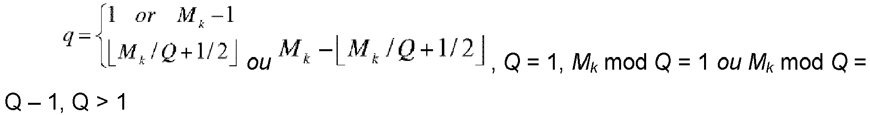 dans lequel└ ┘ représente l'arrondissement par défaut,
 dans lequel une valeur de q est la suivante :
 Mk mod q' = 1 ou Mk mod q' = q' - 1 et 1 ≤ q' ≤ └ Mk / 2┘.
 - Procédé selon la revendication 1, dans lequel une longueur de la séquence de signal de référence est 48, une valeur de Mk et la valeur de q de la séquence de Zadoff-Chu sont un type dans un ensemble de valeurs de paramètres, Mk dans l'ensemble de valeurs de paramètres a au moins deux valeurs différentes et l'ensemble de valeurs de paramètres comprend au moins deux éléments des éléments suivants :Mk = 47 et q = 1 ;Mk = 47 et q = 8 ;Mk = 47 et q = 12 ;Mk = 47 et q = 14 ;Mk = 47 et q = 16 ;Mk = 47 et q = 17 ;Mk = 47 et q = 19 ;Mk = 47 et q = 21 ;Mk = 47 et q = 23 ;Mk = 47 et q = 24 ;Mk = 47 et q = 26 ;Mk = 47 et q = 28 ;Mk = 47 et q = 30 ;Mk = 47 et q = 31 ;Mk = 47 et q = 33 ;Mk = 47 et q = 35 ;Mk = 47 et q = 39 ;Mk = 47 et q = 46 ;Mk = 87 et q = 37 ;Mk = 87 et q = 50 ;Mk = 117 et q = 10 ;Mk = 117 et q = 107 ;Mk = 125 et q = 27 ;Mk = 125 et q = 98 ;Mk = 129 et q = 14 ;Mk = 129 etq = 115 ;Mk = 151 et q = 69 ;Mk = 151 et q = 82 ;Mk = 223 et q = 83 ; etMk = 223 et q = 140.
- Procédé selon la revendication 1 ou 2, dans lequel la séquence de signal de référence est Rq (n), et Rq (n) est déterminé selon Rq (n) = ej·α·nXq (n mod Mk ), dans lequel
n est un entier et 0 ≤ n ≤ N - 1, N représente la longueur de la séquence de signal de référence, N est un entier supérieur à 1, α représente une phase de rotation de phase linéaire et α est un nombre réel. - Procédé selon l'une quelconque des revendications 1 à 3, dans lequella ressource de domaine fréquentiel comprend un premier groupe de ressources de domaine fréquentiel et un second groupe de ressources de domaine fréquentiel, et le second groupe de ressources de domaine fréquentiel et le premier groupe de ressources de domaine fréquentiel comprennent une même quantité d'unités de ressources temps-fréquence minimum et n'ont pas d'unités de ressources temps-fréquence minimum se chevauchant ;la séquence de signal de référence comprend une première séquence de signal de référence et une seconde séquence de signal de référence ; etla première séquence de signal de référence est mappée sur le premier groupe de ressources de domaine fréquentiel, et la seconde séquence de signal de référence est mappée sur le second groupe de ressources de domaine fréquentiel.
- Appareil de communications comprenant :une unité de traitement (610), configurée pour convertir un signal de référence de domaine fréquentiel de domaine fréquentiel en domaine temporel, pour générer un signal de référence de domaine temporel, le signal de référence de domaine fréquentiel comprenant une séquence de signal de référence mappée sur une ressource de domaine fréquentiel, la séquence de signal de référence est déterminée sur la base d'une séquence de Zadoff-Chu, et une valeur de longueur de la séquence de Zadoff-Chu est sélectionnée parmi au moins deux valeurs de longueur ; etune unité d'envoi (620), configurée pour envoyer le signal référence de domaine temporeldans lequel la séquence de Zadoff-Chu est Xq (m), et Xq (m) est déterminé selon
 m représente un numéro de séquence d'un élément de la séquence de Zadoff-Chu, m est un entier et 0 ≤ m ≤ Mk - 1, Mk représente la valeur de longueur de la séquence de Zadoff-Chu, k est un entier et 0 ≤ k ≤ K - 1, K représente une quantité de valeurs de longueur de la séquence de Zadoff-Chu, K est un entier supérieur à 1, q représente une valeur d'une racine de la séquence de Zadoff-Chu, et q et Mk sont relativement premiers ;dans lequel une valeur de q est la suivante :
 └ ┘ représente l'arrondissement par défaut,
 dans lequel une valeur de q est la suivante :
 Mk mod q' = 1 ou Mk mod q' = q'- 1 et 1 ≤ q' ≤ └ Mk / 2┘.
 - Appareil de communication selon la revendication 5, dans lequel une longueur de la séquence de signal de référence est 48, une valeur de Mk et la valeur de q de la séquence de Zadoff-Chu sont un type dans un ensemble de valeurs de paramètres, Mk dans l'ensemble de valeurs de paramètres a au moins deux valeurs différentes et l'ensemble de valeurs de paramètres comprend au moins deux éléments des éléments suivants :Mk = 47 et q = 1 ;Mk = 47 et q = 8 ;Mk = 47 et q = 12 ;Mk = 47 et q = 14 ;Mk = 47 et q = 16 ;Mk = 47 et q = 17 ;Mk = 47 et q = 19 ;Mk = 47 et q = 21 ;Mk = 47 et q = 23 ;Mk = 47 et q = 24 ;Mk = 47 et q = 26 ;Mk = 47 et q = 28 ;Mk = 47 et q = 30 ;Mk = 47 et q = 31 ;Mk = 47 et q = 33 ;Mk = 47 et q = 35 ;Mk = 47 et q = 39 ;Mk = 47 et q = 46 ;Mk = 87 et q = 37 ;Mk = 87 et q = 50 ;Mk = 117 et q = 10 ;Mk = 117 et q = 107 ;Mk = 125 et q = 27 ;Mk = 125 et q = 98 ;Mk = 129 et q = 14 ;Mk = 129 etq = 115 ;Mk = 151 et q = 69 ;Mk = 151 et q = 82 ;Mk = 223 et q = 83 ; etMk = 223 et q = 140.
- Appareil de communication selon la revendication 5 ou 6, dans lequel la séquence de signal de référence est Rq (n), et Rq (n) est déterminé selon Rq (n) = ej·α·nXq (n mod Mk ), dans lequel
n est un entier et 0 ≤ n ≤ N - 1, N représente la longueur de la séquence de signal de référence, N est un entier supérieur à 1, α représente une phase de rotation de phase linéaire et α est un nombre réel. - Appareil de communication selon l'une quelconque des revendications 5 à 7, dans lequella ressource de domaine fréquentiel comprend un premier groupe de ressources de domaine fréquentiel et un second groupe de ressources de domaine fréquentiel, et le second groupe de ressources de domaine fréquentiel et le premier groupe de ressources de domaine fréquentiel comprennent une même quantité d'unités de ressources temps-fréquence minimum et n'ont pas d'unités de ressources temps-fréquence minimum se chevauchant ;la séquence de signal de référence comprend une première séquence de signal de référence et une seconde séquence de signal de référence ; etla première séquence de signal de référence est mappée sur le premier groupe de ressources de domaine fréquentiel, et la seconde séquence de signal de référence est mappée sur le second groupe de ressources de domaine fréquentiel, dans lequelm est le numéro de séquence de l'élément de la séquence de Zadoff-Chu, m est un entier et 0 ≤ m ≤ Mk - 1, Mk représente la valeur de longueur de la séquence de Zadoff-Chu, k est un entier et 0 ≤ k ≤ K - 1, K est la quantité de valeurs de longueur de la séquence de Zadoff-Chu, K est un entier supérieur à 1, q est la valeur de la racine de la séquence de Zadoff-Chu et q et Mk sont relativement premiers.
- Support de stockage lisible par ordinateur, configuré pour stocker un programme informatique ou une instruction, dans lequel lorsque le programme informatique ou l'instruction s'exécute sur un ordinateur, l'ordinateur effectue le procédé suivant selon l'une quelconque des revendications 1 à 4.
Applications Claiming Priority (2)
| Application Number | Priority Date | Filing Date | Title |
|---|---|---|---|
| CN201710011406.3A CN108282305B (zh) | 2017-01-06 | 2017-01-06 | 参考信号的传输方法和设备 |
| PCT/CN2018/071464 WO2018127111A1 (fr) | 2017-01-06 | 2018-01-04 | Procédé et appareil d'émission de signal de référence |
Publications (3)
| Publication Number | Publication Date |
|---|---|
| EP3550760A1 EP3550760A1 (fr) | 2019-10-09 |
| EP3550760A4 EP3550760A4 (fr) | 2019-12-11 |
| EP3550760B1 true EP3550760B1 (fr) | 2022-03-09 |
Family
ID=62791276
Family Applications (1)
| Application Number | Title | Priority Date | Filing Date |
|---|---|---|---|
| EP18736499.7A Active EP3550760B1 (fr) | 2017-01-06 | 2018-01-04 | Procédé et appareil d'émission de signal de référence |
Country Status (5)
| Country | Link |
|---|---|
| US (1) | US11095408B2 (fr) |
| EP (1) | EP3550760B1 (fr) |
| KR (1) | KR20190095431A (fr) |
| CN (1) | CN108282305B (fr) |
| WO (1) | WO2018127111A1 (fr) |
Families Citing this family (18)
| Publication number | Priority date | Publication date | Assignee | Title |
|---|---|---|---|---|
| CN108289021B (zh) * | 2017-01-09 | 2021-10-01 | 华为技术有限公司 | 参考信号的传输方法和设备 |
| WO2019031927A1 (fr) * | 2017-08-10 | 2019-02-14 | 엘지전자 주식회사 | Procédé et dispositif de transmission d'autorisation relative à une transmission de liaison latérale dans un système de communication sans fil |
| CN110868279B (zh) * | 2018-08-27 | 2021-09-14 | 华为技术有限公司 | 一种信号发送、接收方法及装置 |
| CN111147215B (zh) * | 2018-11-02 | 2021-10-15 | 华为技术有限公司 | 无线通信方法、装置及系统 |
| CN111277358A (zh) * | 2018-12-28 | 2020-06-12 | 维沃移动通信有限公司 | 序列生成方法、信号接收方法及装置、终端 |
| CN115189855B (zh) | 2019-01-10 | 2025-02-21 | 华为技术有限公司 | 信号处理的方法和装置 |
| US20200228299A1 (en) * | 2019-01-11 | 2020-07-16 | Mediatek Inc. | Ue multiplexing for dmrs transmission |
| US11824637B2 (en) * | 2019-05-22 | 2023-11-21 | At&T Intellectual Property I, L.P. | Generating wireless reference signals in a different domain for transmission |
| CN112332943B (zh) * | 2019-08-01 | 2022-02-18 | 华为技术有限公司 | 参考信号的处理方法和装置 |
| WO2021062872A1 (fr) * | 2019-10-03 | 2021-04-08 | 华为技术有限公司 | Procédé et dispositif de communication |
| CN111901890A (zh) * | 2020-01-16 | 2020-11-06 | 中兴通讯股份有限公司 | 参考信号处理方法、装置、第一通信节点和第二通信节点 |
| WO2022082792A1 (fr) * | 2020-10-23 | 2022-04-28 | 华为技术有限公司 | Procédé et appareil de transmission de signal et de détection de signal |
| CN112350816B (zh) * | 2020-11-12 | 2023-01-17 | 海能达通信股份有限公司 | 一种数据传输方法、存储介质和通信设备 |
| FI20215005A1 (en) | 2021-01-04 | 2022-07-05 | Nokia Technologies Oy | Reference signal arrangement |
| KR20220101473A (ko) * | 2021-01-11 | 2022-07-19 | 삼성전자주식회사 | 무선 통신 시스템에서 제어 채널 전송을 위한 장치 및 방법 |
| CN115412939B (zh) * | 2022-08-25 | 2024-09-20 | 比科奇微电子(杭州)有限公司 | Zc序列的生成方法、装置、设备、介质和程序产品 |
| CN119544436A (zh) * | 2023-08-29 | 2025-02-28 | 华为技术有限公司 | 一种通信方法及装置 |
| CN120934961A (zh) * | 2024-05-11 | 2025-11-11 | 华为技术有限公司 | 通信方法及装置 |
Family Cites Families (10)
| Publication number | Priority date | Publication date | Assignee | Title |
|---|---|---|---|---|
| GB2458418B (en) * | 2006-12-19 | 2011-08-03 | Lg Electronics Inc | Sequence generating method for efficient detection and method for transmitting and receiving signals using the same |
| US8711814B2 (en) | 2007-09-28 | 2014-04-29 | Panasonic Corporation | Radio communication device and sequence length adjusting method |
| US20100284265A1 (en) * | 2007-12-27 | 2010-11-11 | Panasonic Corporation | Sequence number establishing method, wireless communication terminal apparatus and wireless communication base station apparatus |
| WO2010020291A1 (fr) * | 2008-08-22 | 2010-02-25 | Telefonaktiebolaget Lm Ericsson (Publ) | Génération de séquence de zadoff-chu efficace |
| US8374072B2 (en) * | 2010-04-07 | 2013-02-12 | Qualcomm Incorporated | Efficient zadoff-chu sequence generation |
| CN101917356A (zh) * | 2010-07-19 | 2010-12-15 | 中国科学院计算技术研究所 | LTE系统上行参考信号q阶ZC序列的生成方法及其系统 |
| CN102769592B (zh) * | 2011-05-04 | 2015-03-18 | 普天信息技术研究院有限公司 | 一种用于通信系统的上行参考信号的生成方法及装置 |
| CN103873215B (zh) * | 2012-12-17 | 2017-12-05 | 中兴通讯股份有限公司 | 增强物理混合自动重传请求指示信道传输方法及装置 |
| CN104202712B (zh) | 2014-01-24 | 2019-07-23 | 中兴通讯股份有限公司 | 设备到设备同步信号的发送方法及装置、用户设备 |
| JP6893241B2 (ja) * | 2016-12-19 | 2021-06-23 | オッポ広東移動通信有限公司Guangdong Oppo Mobile Telecommunications Corp., Ltd. | 信号の伝送方法、ネットワーク装置及び端末装置 |
-
2017
- 2017-01-06 CN CN201710011406.3A patent/CN108282305B/zh active Active
-
2018
- 2018-01-04 KR KR1020197021152A patent/KR20190095431A/ko not_active Ceased
- 2018-01-04 WO PCT/CN2018/071464 patent/WO2018127111A1/fr not_active Ceased
- 2018-01-04 EP EP18736499.7A patent/EP3550760B1/fr active Active
-
2019
- 2019-07-02 US US16/460,201 patent/US11095408B2/en active Active
Also Published As
| Publication number | Publication date |
|---|---|
| EP3550760A1 (fr) | 2019-10-09 |
| WO2018127111A1 (fr) | 2018-07-12 |
| KR20190095431A (ko) | 2019-08-14 |
| CN108282305A (zh) | 2018-07-13 |
| CN108282305B (zh) | 2021-09-14 |
| US11095408B2 (en) | 2021-08-17 |
| EP3550760A4 (fr) | 2019-12-11 |
| US20190327053A1 (en) | 2019-10-24 |
Similar Documents
| Publication | Publication Date | Title |
|---|---|---|
| EP3550760B1 (fr) | Procédé et appareil d'émission de signal de référence | |
| US20220400471A1 (en) | Method for sending physical uplink shared channel and apparatus | |
| US11018830B2 (en) | Reference signal transmission method and apparatus | |
| US11153134B2 (en) | Reference signal transmission method, apparatus, and system | |
| US11139906B2 (en) | Wireless communication method and wireless communications apparatus | |
| EP3595385B1 (fr) | Procédé et dispositif de transmission | |
| JP2022179624A (ja) | 検出ウィンドウ指示方法及び装置 | |
| US10616019B2 (en) | Signal sending method, terminal device, and network device | |
| US20240372668A1 (en) | Method for determining frequency-domain resource position, terminal, and storage medium | |
| US20180076980A1 (en) | Terminal device, wireless transmission method, base station device, and channel estimation method | |
| CN108282309B (zh) | 参考信号传输方法和设备 | |
| WO2018127137A1 (fr) | Procédé et appareil de transmission de signal de référence | |
| WO2022147735A1 (fr) | Procédé et appareil de détermination d'une puissance d'émission | |
| US20230208594A1 (en) | Communication method and apparatus | |
| CN103944662A (zh) | 一种发射上行解调参考信号的方法和系统 | |
| WO2020164461A1 (fr) | Procédé de transmission de liaison descendante, et dispositif associé | |
| EP3840281B1 (fr) | Procédé et appareil de communication | |
| CN111294306B (zh) | 一种参考信号的传输方法及装置 | |
| CN107733596A (zh) | 信息传输方法和设备 | |
| WO2020220475A1 (fr) | Procédé et dispositif de communication | |
| CN119921920A (zh) | 通信方法及装置 | |
| CN115706690A (zh) | 信号处理方法及装置 |
Legal Events
| Date | Code | Title | Description |
|---|---|---|---|
| STAA | Information on the status of an ep patent application or granted ep patent |
Free format text: STATUS: THE INTERNATIONAL PUBLICATION HAS BEEN MADE |
|
| PUAI | Public reference made under article 153(3) epc to a published international application that has entered the european phase |
Free format text: ORIGINAL CODE: 0009012 |
|
| STAA | Information on the status of an ep patent application or granted ep patent |
Free format text: STATUS: REQUEST FOR EXAMINATION WAS MADE |
|
| 17P | Request for examination filed |
Effective date: 20190704 |
|
| AK | Designated contracting states |
Kind code of ref document: A1 Designated state(s): AL AT BE BG CH CY CZ DE DK EE ES FI FR GB GR HR HU IE IS IT LI LT LU LV MC MK MT NL NO PL PT RO RS SE SI SK SM TR |
|
| AX | Request for extension of the european patent |
Extension state: BA ME |
|
| REG | Reference to a national code |
Ref country code: DE Ref legal event code: R079 Ref document number: 602018031985 Country of ref document: DE Free format text: PREVIOUS MAIN CLASS: H04L0005000000 Ipc: H04L0027260000 |
|
| A4 | Supplementary search report drawn up and despatched |
Effective date: 20191111 |
|
| RIC1 | Information provided on ipc code assigned before grant |
Ipc: H04L 27/26 20060101AFI20191105BHEP |
|
| DAV | Request for validation of the european patent (deleted) | ||
| DAX | Request for extension of the european patent (deleted) | ||
| GRAP | Despatch of communication of intention to grant a patent |
Free format text: ORIGINAL CODE: EPIDOSNIGR1 |
|
| STAA | Information on the status of an ep patent application or granted ep patent |
Free format text: STATUS: GRANT OF PATENT IS INTENDED |
|
| INTG | Intention to grant announced |
Effective date: 20210910 |
|
| GRAS | Grant fee paid |
Free format text: ORIGINAL CODE: EPIDOSNIGR3 |
|
| GRAA | (expected) grant |
Free format text: ORIGINAL CODE: 0009210 |
|
| STAA | Information on the status of an ep patent application or granted ep patent |
Free format text: STATUS: THE PATENT HAS BEEN GRANTED |
|
| AK | Designated contracting states |
Kind code of ref document: B1 Designated state(s): AL AT BE BG CH CY CZ DE DK EE ES FI FR GB GR HR HU IE IS IT LI LT LU LV MC MK MT NL NO PL PT RO RS SE SI SK SM TR |
|
| REG | Reference to a national code |
Ref country code: CH Ref legal event code: EP Ref country code: AT Ref legal event code: REF Ref document number: 1475074 Country of ref document: AT Kind code of ref document: T Effective date: 20220315 |
|
| REG | Reference to a national code |
Ref country code: DE Ref legal event code: R096 Ref document number: 602018031985 Country of ref document: DE |
|
| REG | Reference to a national code |
Ref country code: IE Ref legal event code: FG4D |
|
| REG | Reference to a national code |
Ref country code: LT Ref legal event code: MG9D |
|
| REG | Reference to a national code |
Ref country code: NL Ref legal event code: MP Effective date: 20220309 |
|
| PG25 | Lapsed in a contracting state [announced via postgrant information from national office to epo] |
Ref country code: SE Free format text: LAPSE BECAUSE OF FAILURE TO SUBMIT A TRANSLATION OF THE DESCRIPTION OR TO PAY THE FEE WITHIN THE PRESCRIBED TIME-LIMIT Effective date: 20220309 Ref country code: RS Free format text: LAPSE BECAUSE OF FAILURE TO SUBMIT A TRANSLATION OF THE DESCRIPTION OR TO PAY THE FEE WITHIN THE PRESCRIBED TIME-LIMIT Effective date: 20220309 Ref country code: NO Free format text: LAPSE BECAUSE OF FAILURE TO SUBMIT A TRANSLATION OF THE DESCRIPTION OR TO PAY THE FEE WITHIN THE PRESCRIBED TIME-LIMIT Effective date: 20220609 Ref country code: LT Free format text: LAPSE BECAUSE OF FAILURE TO SUBMIT A TRANSLATION OF THE DESCRIPTION OR TO PAY THE FEE WITHIN THE PRESCRIBED TIME-LIMIT Effective date: 20220309 Ref country code: HR Free format text: LAPSE BECAUSE OF FAILURE TO SUBMIT A TRANSLATION OF THE DESCRIPTION OR TO PAY THE FEE WITHIN THE PRESCRIBED TIME-LIMIT Effective date: 20220309 Ref country code: BG Free format text: LAPSE BECAUSE OF FAILURE TO SUBMIT A TRANSLATION OF THE DESCRIPTION OR TO PAY THE FEE WITHIN THE PRESCRIBED TIME-LIMIT Effective date: 20220609 |
|
| REG | Reference to a national code |
Ref country code: AT Ref legal event code: MK05 Ref document number: 1475074 Country of ref document: AT Kind code of ref document: T Effective date: 20220309 |
|
| PG25 | Lapsed in a contracting state [announced via postgrant information from national office to epo] |
Ref country code: LV Free format text: LAPSE BECAUSE OF FAILURE TO SUBMIT A TRANSLATION OF THE DESCRIPTION OR TO PAY THE FEE WITHIN THE PRESCRIBED TIME-LIMIT Effective date: 20220309 Ref country code: GR Free format text: LAPSE BECAUSE OF FAILURE TO SUBMIT A TRANSLATION OF THE DESCRIPTION OR TO PAY THE FEE WITHIN THE PRESCRIBED TIME-LIMIT Effective date: 20220610 Ref country code: FI Free format text: LAPSE BECAUSE OF FAILURE TO SUBMIT A TRANSLATION OF THE DESCRIPTION OR TO PAY THE FEE WITHIN THE PRESCRIBED TIME-LIMIT Effective date: 20220309 |
|
| PG25 | Lapsed in a contracting state [announced via postgrant information from national office to epo] |
Ref country code: NL Free format text: LAPSE BECAUSE OF FAILURE TO SUBMIT A TRANSLATION OF THE DESCRIPTION OR TO PAY THE FEE WITHIN THE PRESCRIBED TIME-LIMIT Effective date: 20220309 |
|
| PG25 | Lapsed in a contracting state [announced via postgrant information from national office to epo] |
Ref country code: SM Free format text: LAPSE BECAUSE OF FAILURE TO SUBMIT A TRANSLATION OF THE DESCRIPTION OR TO PAY THE FEE WITHIN THE PRESCRIBED TIME-LIMIT Effective date: 20220309 Ref country code: SK Free format text: LAPSE BECAUSE OF FAILURE TO SUBMIT A TRANSLATION OF THE DESCRIPTION OR TO PAY THE FEE WITHIN THE PRESCRIBED TIME-LIMIT Effective date: 20220309 Ref country code: RO Free format text: LAPSE BECAUSE OF FAILURE TO SUBMIT A TRANSLATION OF THE DESCRIPTION OR TO PAY THE FEE WITHIN THE PRESCRIBED TIME-LIMIT Effective date: 20220309 Ref country code: PT Free format text: LAPSE BECAUSE OF FAILURE TO SUBMIT A TRANSLATION OF THE DESCRIPTION OR TO PAY THE FEE WITHIN THE PRESCRIBED TIME-LIMIT Effective date: 20220711 Ref country code: ES Free format text: LAPSE BECAUSE OF FAILURE TO SUBMIT A TRANSLATION OF THE DESCRIPTION OR TO PAY THE FEE WITHIN THE PRESCRIBED TIME-LIMIT Effective date: 20220309 Ref country code: EE Free format text: LAPSE BECAUSE OF FAILURE TO SUBMIT A TRANSLATION OF THE DESCRIPTION OR TO PAY THE FEE WITHIN THE PRESCRIBED TIME-LIMIT Effective date: 20220309 Ref country code: CZ Free format text: LAPSE BECAUSE OF FAILURE TO SUBMIT A TRANSLATION OF THE DESCRIPTION OR TO PAY THE FEE WITHIN THE PRESCRIBED TIME-LIMIT Effective date: 20220309 Ref country code: AT Free format text: LAPSE BECAUSE OF FAILURE TO SUBMIT A TRANSLATION OF THE DESCRIPTION OR TO PAY THE FEE WITHIN THE PRESCRIBED TIME-LIMIT Effective date: 20220309 |
|
| PG25 | Lapsed in a contracting state [announced via postgrant information from national office to epo] |
Ref country code: PL Free format text: LAPSE BECAUSE OF FAILURE TO SUBMIT A TRANSLATION OF THE DESCRIPTION OR TO PAY THE FEE WITHIN THE PRESCRIBED TIME-LIMIT Effective date: 20220309 Ref country code: IS Free format text: LAPSE BECAUSE OF FAILURE TO SUBMIT A TRANSLATION OF THE DESCRIPTION OR TO PAY THE FEE WITHIN THE PRESCRIBED TIME-LIMIT Effective date: 20220709 Ref country code: AL Free format text: LAPSE BECAUSE OF FAILURE TO SUBMIT A TRANSLATION OF THE DESCRIPTION OR TO PAY THE FEE WITHIN THE PRESCRIBED TIME-LIMIT Effective date: 20220309 |
|
| REG | Reference to a national code |
Ref country code: DE Ref legal event code: R097 Ref document number: 602018031985 Country of ref document: DE |
|
| PLBE | No opposition filed within time limit |
Free format text: ORIGINAL CODE: 0009261 |
|
| STAA | Information on the status of an ep patent application or granted ep patent |
Free format text: STATUS: NO OPPOSITION FILED WITHIN TIME LIMIT |
|
| PG25 | Lapsed in a contracting state [announced via postgrant information from national office to epo] |
Ref country code: DK Free format text: LAPSE BECAUSE OF FAILURE TO SUBMIT A TRANSLATION OF THE DESCRIPTION OR TO PAY THE FEE WITHIN THE PRESCRIBED TIME-LIMIT Effective date: 20220309 |
|
| 26N | No opposition filed |
Effective date: 20221212 |
|
| PG25 | Lapsed in a contracting state [announced via postgrant information from national office to epo] |
Ref country code: SI Free format text: LAPSE BECAUSE OF FAILURE TO SUBMIT A TRANSLATION OF THE DESCRIPTION OR TO PAY THE FEE WITHIN THE PRESCRIBED TIME-LIMIT Effective date: 20220309 |
|
| PG25 | Lapsed in a contracting state [announced via postgrant information from national office to epo] |
Ref country code: IT Free format text: LAPSE BECAUSE OF FAILURE TO SUBMIT A TRANSLATION OF THE DESCRIPTION OR TO PAY THE FEE WITHIN THE PRESCRIBED TIME-LIMIT Effective date: 20220309 |
|
| REG | Reference to a national code |
Ref country code: DE Ref legal event code: R119 Ref document number: 602018031985 Country of ref document: DE |
|
| REG | Reference to a national code |
Ref country code: CH Ref legal event code: PL |
|
| PG25 | Lapsed in a contracting state [announced via postgrant information from national office to epo] |
Ref country code: LU Free format text: LAPSE BECAUSE OF NON-PAYMENT OF DUE FEES Effective date: 20230104 |
|
| REG | Reference to a national code |
Ref country code: BE Ref legal event code: MM Effective date: 20230131 |
|
| PG25 | Lapsed in a contracting state [announced via postgrant information from national office to epo] |
Ref country code: LI Free format text: LAPSE BECAUSE OF NON-PAYMENT OF DUE FEES Effective date: 20230131 Ref country code: DE Free format text: LAPSE BECAUSE OF NON-PAYMENT OF DUE FEES Effective date: 20230801 Ref country code: CH Free format text: LAPSE BECAUSE OF NON-PAYMENT OF DUE FEES Effective date: 20230131 |
|
| PG25 | Lapsed in a contracting state [announced via postgrant information from national office to epo] |
Ref country code: FR Free format text: LAPSE BECAUSE OF NON-PAYMENT OF DUE FEES Effective date: 20230131 Ref country code: BE Free format text: LAPSE BECAUSE OF NON-PAYMENT OF DUE FEES Effective date: 20230131 |
|
| PG25 | Lapsed in a contracting state [announced via postgrant information from national office to epo] |
Ref country code: IE Free format text: LAPSE BECAUSE OF NON-PAYMENT OF DUE FEES Effective date: 20230104 |
|
| PG25 | Lapsed in a contracting state [announced via postgrant information from national office to epo] |
Ref country code: MC Free format text: LAPSE BECAUSE OF FAILURE TO SUBMIT A TRANSLATION OF THE DESCRIPTION OR TO PAY THE FEE WITHIN THE PRESCRIBED TIME-LIMIT Effective date: 20220309 |
|
| PG25 | Lapsed in a contracting state [announced via postgrant information from national office to epo] |
Ref country code: MC Free format text: LAPSE BECAUSE OF FAILURE TO SUBMIT A TRANSLATION OF THE DESCRIPTION OR TO PAY THE FEE WITHIN THE PRESCRIBED TIME-LIMIT Effective date: 20220309 |
|
| PG25 | Lapsed in a contracting state [announced via postgrant information from national office to epo] |
Ref country code: CY Free format text: LAPSE BECAUSE OF FAILURE TO SUBMIT A TRANSLATION OF THE DESCRIPTION OR TO PAY THE FEE WITHIN THE PRESCRIBED TIME-LIMIT; INVALID AB INITIO Effective date: 20180104 |
|
| PG25 | Lapsed in a contracting state [announced via postgrant information from national office to epo] |
Ref country code: HU Free format text: LAPSE BECAUSE OF FAILURE TO SUBMIT A TRANSLATION OF THE DESCRIPTION OR TO PAY THE FEE WITHIN THE PRESCRIBED TIME-LIMIT; INVALID AB INITIO Effective date: 20180104 |
|
| PG25 | Lapsed in a contracting state [announced via postgrant information from national office to epo] |
Ref country code: TR Free format text: LAPSE BECAUSE OF FAILURE TO SUBMIT A TRANSLATION OF THE DESCRIPTION OR TO PAY THE FEE WITHIN THE PRESCRIBED TIME-LIMIT Effective date: 20220309 |
|
| PGFP | Annual fee paid to national office [announced via postgrant information from national office to epo] |
Ref country code: GB Payment date: 20251204 Year of fee payment: 9 |