EP3550895B1 - Procédé de transmission en liaison descendante, station de base, et dispositif terminal - Google Patents
Procédé de transmission en liaison descendante, station de base, et dispositif terminal Download PDFInfo
- Publication number
- EP3550895B1 EP3550895B1 EP17883094.9A EP17883094A EP3550895B1 EP 3550895 B1 EP3550895 B1 EP 3550895B1 EP 17883094 A EP17883094 A EP 17883094A EP 3550895 B1 EP3550895 B1 EP 3550895B1
- Authority
- EP
- European Patent Office
- Prior art keywords
- sets
- base station
- data
- terminal device
- reference signal
- Prior art date
- Legal status (The legal status is an assumption and is not a legal conclusion. Google has not performed a legal analysis and makes no representation as to the accuracy of the status listed.)
- Active
Links
Images




Classifications
-
- H—ELECTRICITY
- H04—ELECTRIC COMMUNICATION TECHNIQUE
- H04W—WIRELESS COMMUNICATION NETWORKS
- H04W52/00—Power management, e.g. Transmission Power Control [TPC] or power classes
- H04W52/04—Transmission power control [TPC]
- H04W52/06—TPC algorithms
- H04W52/14—Separate analysis of uplink or downlink
-
- H—ELECTRICITY
- H04—ELECTRIC COMMUNICATION TECHNIQUE
- H04L—TRANSMISSION OF DIGITAL INFORMATION, e.g. TELEGRAPHIC COMMUNICATION
- H04L5/00—Arrangements affording multiple use of the transmission path
- H04L5/003—Arrangements for allocating sub-channels of the transmission path
- H04L5/0048—Allocation of pilot signals, i.e. of signals known to the receiver
-
- H—ELECTRICITY
- H04—ELECTRIC COMMUNICATION TECHNIQUE
- H04L—TRANSMISSION OF DIGITAL INFORMATION, e.g. TELEGRAPHIC COMMUNICATION
- H04L5/00—Arrangements affording multiple use of the transmission path
- H04L5/0001—Arrangements for dividing the transmission path
- H04L5/0003—Two-dimensional division
- H04L5/0005—Time-frequency
-
- H—ELECTRICITY
- H04—ELECTRIC COMMUNICATION TECHNIQUE
- H04W—WIRELESS COMMUNICATION NETWORKS
- H04W52/00—Power management, e.g. Transmission Power Control [TPC] or power classes
- H04W52/04—Transmission power control [TPC]
- H04W52/06—TPC algorithms
- H04W52/14—Separate analysis of uplink or downlink
- H04W52/143—Downlink power control
-
- H—ELECTRICITY
- H04—ELECTRIC COMMUNICATION TECHNIQUE
- H04W—WIRELESS COMMUNICATION NETWORKS
- H04W52/00—Power management, e.g. Transmission Power Control [TPC] or power classes
- H04W52/04—Transmission power control [TPC]
- H04W52/18—TPC being performed according to specific parameters
- H04W52/24—TPC being performed according to specific parameters using SIR [Signal to Interference Ratio] or other wireless path parameters
-
- H—ELECTRICITY
- H04—ELECTRIC COMMUNICATION TECHNIQUE
- H04W—WIRELESS COMMUNICATION NETWORKS
- H04W52/00—Power management, e.g. Transmission Power Control [TPC] or power classes
- H04W52/04—Transmission power control [TPC]
- H04W52/18—TPC being performed according to specific parameters
- H04W52/24—TPC being performed according to specific parameters using SIR [Signal to Interference Ratio] or other wireless path parameters
- H04W52/243—TPC being performed according to specific parameters using SIR [Signal to Interference Ratio] or other wireless path parameters taking into account interferences
-
- H—ELECTRICITY
- H04—ELECTRIC COMMUNICATION TECHNIQUE
- H04W—WIRELESS COMMUNICATION NETWORKS
- H04W52/00—Power management, e.g. Transmission Power Control [TPC] or power classes
- H04W52/04—Transmission power control [TPC]
- H04W52/30—Transmission power control [TPC] using constraints in the total amount of available transmission power
- H04W52/36—Transmission power control [TPC] using constraints in the total amount of available transmission power with a discrete range or set of values, e.g. step size, ramping or offsets
- H04W52/365—Power headroom reporting
-
- H—ELECTRICITY
- H04—ELECTRIC COMMUNICATION TECHNIQUE
- H04W—WIRELESS COMMUNICATION NETWORKS
- H04W72/00—Local resource management
- H04W72/04—Wireless resource allocation
- H04W72/044—Wireless resource allocation based on the type of the allocated resource
- H04W72/0446—Resources in time domain, e.g. slots or frames
-
- H—ELECTRICITY
- H04—ELECTRIC COMMUNICATION TECHNIQUE
- H04L—TRANSMISSION OF DIGITAL INFORMATION, e.g. TELEGRAPHIC COMMUNICATION
- H04L5/00—Arrangements affording multiple use of the transmission path
- H04L5/0091—Signalling for the administration of the divided path, e.g. signalling of configuration information
- H04L5/0092—Indication of how the channel is divided
-
- H—ELECTRICITY
- H04—ELECTRIC COMMUNICATION TECHNIQUE
- H04W—WIRELESS COMMUNICATION NETWORKS
- H04W52/00—Power management, e.g. Transmission Power Control [TPC] or power classes
- H04W52/04—Transmission power control [TPC]
- H04W52/30—Transmission power control [TPC] using constraints in the total amount of available transmission power
- H04W52/32—TPC of broadcast or control channels
- H04W52/325—Power control of control or pilot channels
-
- H—ELECTRICITY
- H04—ELECTRIC COMMUNICATION TECHNIQUE
- H04W—WIRELESS COMMUNICATION NETWORKS
- H04W72/00—Local resource management
- H04W72/04—Wireless resource allocation
- H04W72/044—Wireless resource allocation based on the type of the allocated resource
- H04W72/0473—Wireless resource allocation based on the type of the allocated resource the resource being transmission power
-
- H—ELECTRICITY
- H04—ELECTRIC COMMUNICATION TECHNIQUE
- H04W—WIRELESS COMMUNICATION NETWORKS
- H04W72/00—Local resource management
- H04W72/20—Control channels or signalling for resource management
- H04W72/23—Control channels or signalling for resource management in the downlink direction of a wireless link, i.e. towards a terminal
-
- H—ELECTRICITY
- H04—ELECTRIC COMMUNICATION TECHNIQUE
- H04W—WIRELESS COMMUNICATION NETWORKS
- H04W72/00—Local resource management
- H04W72/50—Allocation or scheduling criteria for wireless resources
- H04W72/53—Allocation or scheduling criteria for wireless resources based on regulatory allocation policies
-
- H—ELECTRICITY
- H04—ELECTRIC COMMUNICATION TECHNIQUE
- H04W—WIRELESS COMMUNICATION NETWORKS
- H04W72/00—Local resource management
- H04W72/50—Allocation or scheduling criteria for wireless resources
- H04W72/54—Allocation or scheduling criteria for wireless resources based on quality criteria
- H04W72/541—Allocation or scheduling criteria for wireless resources based on quality criteria using the level of interference
Definitions
- Embodiments of this application relate to the communications field, and in particular, to a downlink transmission method, a base station, and a terminal device.
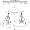
- Self-contained (self-contained) subframes are introduced to the 5th Generation New Radio (5th Generation New Radio, 5G NR) in addition to existing uplink subframes and downlink subframes.
- a structure of a self-contained subframe is shown in FIG 1 .
- the self-contained subframe includes time domain resources for downlink transmission and uplink transmission, and a guard period (Guard Period, GP).
- a base station 1 uses a self-contained subframe for downlink transmission
- a base station 2 uses a downlink subframe for downlink transmission.
- the base station 2 As the tail of the self-contained subframe is used for uplink transmission, if the base station 2 is using the downlink subframe for downlink transmission when the base station 1 is receiving data sent by a terminal device through uplink transmission, the base station 1 is subject to downlink interference from the base station 2.
- base station configuration is not flexible enough to support downlink transmission configuration to reduce interference between base stations.
- ZTE ET AL "Discussion on duplex and interference management", 3GPP DRAFT; R1-1612156, 3RD GENERATION PARTNERSHIP PROJECT (3GPP), MOBILE COMPETENCE CENTRE; 650, ROUTE DES LUCIOLES; F-06921 SOPHIA-ANTIPOLIS CEDEX; FRANCE, vol. RAN WG1, no. Reno, USA discusses duplex, the aspects of interference management and some basic designs for dynamic TDD.
- a proposal is provided that includes options for duplex and cross-link interference mitigation schemes.
- ERICSSON "DL power control for LAA", 3GPP DRAFT; R1-156042, 3RD GENERATION PARTNERSHIP PROJECT (3GPP), MOBILE COMPETENCE CENTRE; 650, ROUTE DES LUCIOLES; F-06921 SOPHIA-ANTIPOLIS CEDEX; FRANCE, vol. RAN WG1, no. Malmo , Sweden discloses that in LTE specification, downlink power control varies a bit between CRS based TMs and TM9/10.
- the CRS transmission power at the eNB is communicated to the UE through RRC signalling from the eNB.
- the power allocated to PDSCH for TM3 and TM4 is set relative to the CRS transmission power.
- NEC "eRNTP Signaling for inter-eNB CoMP", 3GPP DRAFT; R3-150993, 3RD GENERATION PARTNERSHIP PROJECT (3GPP), MOBILE COMPETENCE CENTRE; 650, ROUTE DES LUCIOLES; F-06921 SOPHIA-ANTIPOLIS CEDEX; FRANCE, vol RAN WG3, no. Fukuoka , Japan discloses that an RNTP IE indicating transmit power levels for the first subframe (subframe #0) must always conveyed. The included enhanced RNTP IE can then convey the per-PRB power level information for the second and subsequent subframes.
- Embodiments of this application provide a downlink transmission method, a downlink receiving method, and the corresponding apparatuses, so that flexibility of base station configuration can be improved.
- a downlink transmission method is provided, as defined in claim 1.
- a reference signal and data are sent in a spatial multiplexing manner.
- data can also be transmitted on a time-frequency resource used for reference signal transmission, and data transmission efficiency can be improved.
- a downlink receiving method is provided, as defined in claim 6.
- a reference signal and data are sent in a spatial multiplexing manner.
- data can also be transmitted on a time-frequency resource used for reference signal transmission, and data transmission efficiency can be improved.
- an apparatus as defined in claim 10 provided, and the apparatus is configured to implement the method in any one of the first aspect and the possible implementations of the first aspect.
- the apparatus may include units configured to execute the method in any one of the first aspect and the possible implementations of the first aspect.
- an apparatus as defined in claim 11 is provided, and the apparatus is configured to implement the method in any one of the second aspect and the possible implementations of the second aspect.
- the apparatus may include units configured to execute the method in any one of the second aspect and the possible implementations of the second aspect.
- a Wireless Fidelity (Wi-Fi) system a Worldwide Interoperability for Microwave Access (Worldwide Interoperability for Microwave Access, WiMAX) system, a Global System for Mobile Communications (Global System for Mobile Communications, GSM), a Code Division Multiple Access (Code Division Multiple Access, CDMA) system, a Wideband Code Division Multiple Access (Wideband Code Division Multiple Access, WCDMA) system, a General Packet Radio Service (General Packet Radio Service, GPRS) system, a Long Term Evolution (Long Term Evolution, LTE) system, a Long Term Evolution Advanced (Long Term Evolution Advanced, LTE-A) system, a Universal Mobile Telecommunications System (Universal Mobile Telecommunications System, UMTS), and cellular systems related to the 3rd Generation Partnership Project (The 3rd Generation Partnership Project, 3GPP). This is not limited in the embodiments of this application.
- 3GPP 3rd Generation Partnership Project
- a radio access network may include different network elements in different systems.
- network elements of a radio access network in a 5G network include a gNB
- network elements of a radio access network in Long Term Evolution (Long Term Evolution, LTE) or LTE-A include an eNB (eNodeB, eNB)
- network elements of a radio access network in WCDMA Wideband Code Division Multiple Access, Wideband Code Division Multiple Access
- RNC Radio Network Controller
- a solution similar to that in the embodiments of this application may also be used, with only differences in related modules in a base station system. This is not limited in the embodiments of this application. However, for ease of description, a base station is used as an example for description in the embodiments of this application.
- a terminal device may also be referred to as user equipment (User Equipment, UE), a mobile station (Mobile Station, MS), a mobile terminal (Mobile Terminal), and the like.
- the terminal device may communicate with one or more core networks through a radio access network (Radio Access Network, RAN).
- RAN Radio Access Network
- the terminal device may be a mobile phone (or referred to as a "cellular" phone), or a computer having a communication function.
- the terminal device may alternatively be a portable, pocket-sized, handheld, computer built-in, or in-vehicle mobile apparatus.
- An embodiment of this application provides a reference signal transmission method.
- a base station may send a reference signal and data to a terminal device in a spatial multiplexing manner on a time-frequency resource corresponding to a pattern of the reference signal.
- a time-frequency resource used for reference signal transmission can also be used for data transmission, so that data transmission efficiency can be improved.
- FIG. 3 is a schematic flowchart of a downlink transmission method 300 according to an embodiment of this application. As shown in FIG. 3 , the method 300 includes the following content.
- a base station divides to-be-transmitted data into at least two sets, and configures a transmit power for each of the at least two sets.
- a terminal device determines the at least two sets obtained through division of the to-be-transmitted data by the base station, and determines power information of each of the at least two sets.
- the power information of each set indicates the transmit power configured for each set.
- the power information of each set may be the transmit power configured for each set.
- the power information of each set may be a relative value of the transmit power configured for each set to a preset power.
- the power information of each set may be a difference between the transmit power for each set and a preset power or a ratio of the transmit power for each set to a preset power.
- the preset power may be pre-agreed by the base station and the terminal device, or may be protocol-specified.
- the preset power may be a protocol-specified power for a demodulation reference signal (Demodulation Reference Signal, DMRS).
- DMRS Demodulation Reference Signal
- the base station sends data in each set to the terminal device at a transmit power configured for each set. Specifically, the base station sends the data in each set to the terminal device by using the transmit power configured for each set.
- the terminal device receives the data in each set from the base station based on the power information of each set.
- the to-be-transmitted data is divided into the at least two sets, a transmit power is configured individually for each set, and the data in each set is sent to the terminal device at the transmit power configured for each set. In this way, flexibility of base station configuration can be improved.
- the base station configures a relatively low transmit power for downlink transmission data that may cause interference to a base station in a neighboring cell, and interference to the base station in the neighboring cell can thereby be reduced. Therefore, this embodiment of this application helps reduce interference between base stations.
- the terminal device may use a plurality of methods, to determine the at least two sets obtained through division of the to-be-transmitted data by the base station and the power information of each of the at least two sets. This is not limited in this embodiment of this application.
- a terminal device determines the at least two sets obtained through division of the to-be-transmitted data by the base station, and determines power information of each of the at least two sets includes, that the terminal device receives indication information from the base station, where the indication information indicates the at least two sets and the power information of each of the at least two sets.
- the indication information may be carried in higher layer signaling, media access control (Media Access Control, MAC) layer signaling, or physical layer signaling. This is not limited in this embodiment of this application.
- a rule for division into the at least two sets, and the indication information of the power information of each of the at least two sets may be pre-stored in the terminal device.
- the terminal device may determine the at least two sets based on the pre-stored division rule, and determine the power information of each set according to the pre-stored indication information.
- FIG. 4 shows another embodiment of the method 300 shown in FIG. 3 .
- step 310 that a base station divides to-be-transmitted data into at least two sets includes the following steps:
- the neighboring cell is a cell that can receive interference from the base station.
- the base station when determining that the self-contained subframe is used for transmission in the neighboring cell, divides the to-be-transmitted data into the at least two sets based on a structure of the self-contained subframe, and configures a transmit power individually for each of the at least two sets. This enables flexible adjustment of a transmit power used when data is transmitted on different time domain resources of the self-contained subframe.
- a relatively low transmit power is configured for a set mapped to a time domain resource used for uplink transmission in the self-contained subframe, and interference to signal reception of a base station in a neighboring cell can thereby be reduced.
- the base station in the neighboring cell may configure a relatively low power value for a transmit power for the sent data, to reduce interference to the base station in the neighboring cell. If the base station in the neighboring cell is also sending downlink data when the base station is sending downlink data, the base station does not interfere with the base station in the neighboring cell. In this case, the base station may configure a normal or a relatively high power value for a transmit power for the sent data, to help detection of the terminal device.
- the to-be-transmitted data is divided into the at least two sets with a transmit power configured individually for each of the at least two sets. This enables flexible transmit power configuration for the to-be-transmitted data, and interference between the base stations is reduced.
- the method 300 further includes: sending, by the base station, subframe configuration information of the neighboring cell to the terminal device, where the subframe configuration information indicates that a self-contained subframe is used for transmission in the neighboring cell.
- the terminal device may determine, based on the subframe configuration information, the at least two sets obtained through division of the to-be-transmitted data by the base station, and determine the power information of each of the at least two sets, where at least one of the at least two sets is transmitted by using a time domain resource, in the self-contained subframe, used for uplink transmission in the neighboring cell, and a set of the at least two sets other than the at least one set is transmitted by using a time domain resource, in the self-contained subframe, used for downlink transmission in the neighboring cell.
- a set division rule for the to-be-transmitted data and the power information of each set are pre-agreed by the terminal device and the base station, or protocol-specified, or pre-stored in the terminal device. Therefore, when determining that the self-contained subframe is used for transmission in the neighboring cell, the terminal device may determine, based on the division rule, the at least two sets obtained through division of the to-be-transmitted data by the base station, and determine the power information of each of the at least two sets.
- FIG. 5 shows another embodiment of the method 300 shown in FIG. 3 .
- the at least two sets include a first set and a second set, where the first set and a reference signal occupy a same time-frequency resource, and the second set and the reference signal occupy different time-frequency resources.
- Data in the first set and the reference signal may be sent in a spatial multiplexing manner.
- the base station may divide the to-be-transmitted data into the at least two sets based on time-frequency resources occupied by the to-be-transmitted data.
- the terminal device may further obtain a pattern of the reference signal. How the terminal device obtains the pattern of the reference signal is not limited in this embodiment of this application.
- the method 100 may further include: 321.
- the base station sends configuration information of the reference signal to the terminal device, where the configuration information of the reference signal includes the pattern (pattern) of the reference signal.
- the terminal device may receive the pattern of the reference signal from the base station.
- the pattern of the reference signal may be pre-stored in the terminal device.
- the configuration information of the reference signal may further include a sequence of the reference signal.
- the configuration information of the reference signal may be sent to the terminal device by using higher layer signaling.
- step 330 that the base station sends data in the at least two sets to the terminal device at the transmit powers configured for each set includes the following steps:
- the base station may further configure a transmit power for the reference signal.
- the base station may send the reference signal based on the configured transmit power through the first logical port.
- the reference signal may be used to measure a channel state or channel quality, and may be further used to measure interference between a plurality of users.
- the reference signal may be a channel state information reference signal (Channel State Information Reference Signal, CSI-RS) or a demodulation reference signal (Demodulation Reference Signal, DMRS).
- CSI-RS Channel State Information Reference Signal
- DMRS Demodulation Reference Signal
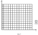
- patterns of the CSI-RS and CSI-RS may be different.
- the CSI-RS may occupy two orthogonal frequency division multiplexing (Orthogonal Frequency Division Multiplexing, OFDM) symbols.
- OFDM Orthogonal Frequency Division Multiplexing
- the DMRS may occupy the first OFDM symbol in a resource block (Resource Block), the first OFDM symbol and the second OFDM symbol in the resource block may be used to transmit control channels, and the DMRS may be carried in a control channel transmitted in the first OFDM symbol.
- Resource Block Resource Block
- FIG. 6 and FIG. 7 are merely examples. Patterns of the CSI-RS and DMRS are not limited in this embodiment of this application.
- the terminal device may determine the pattern of the reference signal. Then, on the time-frequency resource corresponding to the pattern of the reference signal, the terminal device receives the reference signal through the first logical port, and receives the data in the first set through the second logical port.
- the first logical port and the second logical port may correspond to different transport layers. It should be noted that the first logical port may be one or more logical ports, and that the second logical port may be one or more logical ports.
- the base station may send a reference signal and data to one or more terminal devices in a spatial multiplexing manner.
- a reference signal and data that are sent in a spatial multiplexing manner may be sent together to one terminal device, or may be sent together to a plurality of terminal devices, or may be sent separately to different terminal devices.
- a base station when sending data, sends, to a terminal device, indication information such as a location of a time-frequency resource used for reference signal transmission, and when performing resource mapping for data, the base station avoids the location of the time-frequency resource occupied by a reference signal.
- the terminal device may also avoid the location of the time-frequency resource occupied by a reference signal based on the indication from the base station.
- time-frequency resources containing the reference signal are punctured.
- the time-frequency resources occupied by the reference signal are unable to transmit data.
- a reference signal and data are sent in a spatial multiplexing manner.
- data can also be transmitted on a time-frequency resource used for reference signal transmission, and data transmission efficiency can be improved.
- the base station may determine to send a reference signal and data to the terminal device in a spatial multiplexing manner.
- the base station may determine to send the reference signals and data to the terminal device in a spatial multiplexing manner. For example, when the quantity of to-be-transmitted reference signals is less than or equal to a preset threshold, the base station determines to send the reference signals and data to the terminal device in a spatial multiplexing manner on the time-frequency resource used for reference signal transmission.
- the terminal device may receive the signals on the time-frequency resource corresponding to the pattern of the reference signal through at least one logical port.
- the terminal device may further obtain power information of the reference signal.
- the power information of the reference signal indicates power for the reference signal.
- the power information of the reference signal may be the power for the reference signal.
- the power information of the reference signal may be a relative value of the power for the reference signal to another power.
- the power information of the reference signal may be a difference between the transmit power for each set and a preset power or a ratio of the transmit power for each set to a preset power.
- the preset power may be pre-agreed by the base station and the terminal device, or may be protocol-specified.
- the preset power may be a protocol-specified power for a DMRS.
- the terminal device may obtain a correspondence between logical ports and a reference signal and data that are sent by the base station in a spatial multiplexing manner. For example, the terminal device may receive, from the base station, indication information used to indicate the correspondence, and determine the correspondence based on the indication information.
- the terminal device may receive signals through different logical ports, and then perform power detection on the received signal, and determine, based on power information of data and/or a reference signal, whether the received signal is a reference signal or a data signal.
- the base station indicates to the terminal device the power information of the reference signal and/or the data that are/is sent in a spatial multiplexing manner, so that the terminal device can determine, based on the power information and a power detection result, the correspondence between logical ports and a reference signal and data. Then, the terminal device may demodulate the reference signal and the data separately.
- the base station and the terminal device may also pre-agree the correspondence between logical ports and a reference signal and data.
- the terminal device may pre-configure the correspondence, so that the terminal device can receive a reference signal and data through corresponding logical ports according to the correspondence.
- the base station may configure the correspondence between logical ports and a reference signal and data, and indicate the correspondence to the terminal device.
- the correspondence between logical ports and a reference signal and data that are sent in a spatial multiplexing manner is directly indicated to the terminal device, so that the terminal device does not need to determine, based on a power detection result, the correspondence between logical ports and a reference signal and data.
- sequence numbers of the foregoing processes do not mean execution orders.
- the execution orders of the processes should be determined based on functions and internal logic of the processes, and should not be construed as any limitation on the implementation processes of the embodiments of this application.
- FIG. 8 is a schematic structural diagram of a base station 800 according to an embodiment of this application. As shown in FIG. 8 , the base station 800 includes a processing unit 810 and a sending unit 820.
- the processing unit 810 is configured to divide to-be-transmitted data into at least two sets, and configure a transmit power for each of the at least two sets.
- the sending unit 820 is configured to send data in each set to a terminal device at the transmit power configured for each set by the processing unit.
- the to-be-transmitted data is divided into the at least two sets, a transmit power is configured individually for each set, and the data in each set is sent to the terminal device at the transmit power configured for each set. In this way, flexibility of base station configuration can be improved.
- the sending unit 820 is further configured to send indication information to the terminal device, where the indication information indicates the at least two sets and power information of each of the at least two sets.
- the power information of each set is a difference between the transmit power for each set and a preset power or a ratio of the transmit power for each set to a preset power.
- processing unit 810 is specifically configured to:
- the sending unit 820 is further configured to send subframe configuration information of the neighboring cell to the terminal device, where the subframe configuration information indicates that a self-contained subframe is used for transmission in the neighboring cell.
- the at least two sets include a first set and a second set, where the first set and a reference signal occupy a same time-frequency resource, and the second set and the reference signal occupy different time-frequency resources.
- the sending unit 820 is specifically configured to:
- the base station 800 according to this embodiment of this application may be corresponding to the base station in the downlink transmission method 300 according to the embodiments of this application, and the foregoing and other operations and/or functions of the units according to the base station 800 are intended to implement corresponding processes of the method 300 in FIG. 3 to FIG. 5 .
- the base station 800 may be corresponding to the base station in the downlink transmission method 300 according to the embodiments of this application, and the foregoing and other operations and/or functions of the units according to the base station 800 are intended to implement corresponding processes of the method 300 in FIG. 3 to FIG. 5 .
- details are not described herein again.
- the sending unit 820 may be implemented by a transmitter, and the processing unit 810 may be implemented by a processor.
- FIG. 9 is a schematic structural diagram of a base station 900 according to another embodiment of this application.
- the base station 900 includes a processor 910, a transmitter 920, and a memory 930, and the processor 910, the transmitter 920, and the memory 930 communicate with each other through internal connection paths to transfer a control signal and/or a data signal.
- the memory 930 is configured to store an instruction
- the processor 910 is configured to execute the instruction stored in the memory 930.
- the transmitter 920 is configured to implement a function of the sending unit 820 in the base station 800 shown in FIG. 8 .
- the processor 910 is configured to implement a function of the processing unit 810 in the base station 800 shown in FIG. 8 .
- details are not described herein again.
- the base station 900 according to this embodiment of this application may be corresponding to the base station in the downlink transmission method 300 according to the embodiments of this application and the base station 800 according to the embodiments of this application, and the foregoing and other operations and/or functions of the units in the base station 900 are intended to implement corresponding processes of the method 300 in FIG. 3 to FIG. 5 .
- details are not described herein again.
- FIG. 10 is a schematic structural diagram of a terminal device 1000 according to an embodiment of this application. As shown in FIG. 10 , the terminal device 1000 includes a processing unit 1010 and a receiving unit 1020.
- the processing unit 1010 is configured to determine at least two sets obtained through division of to-be-transmitted data by a base station, and determine power information of each of the at least two sets.
- the receiving unit 1020 is configured to receive data in each set from the base station based on the power information of each set determined by the processing unit 1010.
- the terminal device can receive the data in each set based on the power information of each set.
- the receiving unit 1020 is further configured to receive indication information from the base station, where the indication information indicates the at least two sets and the power information of each of the at least two sets.
- the processing unit 1010 is specifically configured to determine the at least two sets and the power information of each set based on the indication information received by the receiving unit 1020.
- the power information of each set is a difference between the transmit power for each set and a preset power or a ratio of the transmit power for each set to a preset power.
- the receiving unit 1020 is further configured to receive subframe configuration information of a neighboring cell from the base station, where the subframe configuration information indicates that a self-contained subframe is used for transmission in the neighboring cell.
- the processing unit 1020 is specifically configured to, based on the subframe configuration information received by the processing unit 1020, determine the at least two sets obtained through division of the to-be-transmitted data by the base station and the power information of each set, where at least one of the at least two sets is transmitted by using a time domain resource, in the self-contained subframe, used for uplink transmission in the neighboring cell, and a set of the at least two sets other than the at least one set is transmitted by using a time domain resource, in the self-contained subframe, used for downlink transmission in the neighboring cell.
- the at least two sets include a first set and a second set, where the first set and a reference signal occupy a same time-frequency resource, and the second set and the reference signal occupy different time-frequency resources.
- the receiving unit 1020 is specifically configured to:
- terminal device 1000 may be corresponding to the terminal device in the downlink transmission method 300 according to the embodiments of this application, and the foregoing and other operations and/or functions of the units in the terminal device 1000 are intended to implement corresponding processes of the method 300 in FIG. 3 to FIG. 5 .
- details are not described herein again.
- receiving unit 1020 may be implemented by a receiver
- processing unit 1010 may be implemented by a processor
- FIG. 11 is a schematic structural diagram of a terminal device 1100 according to another embodiment of this application.
- the terminal device 1100 includes a processor 1110, a receiver 1120, and a memory 1130, and the processor 1110, the receiver 1120, and the memory 1130 communicate with each other through internal connection paths to transfer a control signal and/or a data signal.
- the memory 1130 is configured to store an instruction
- the processor 1110 is configured to execute the instruction stored in the memory 1130.
- the receiver 1120 is configured to implement a function of the receiving unit 1020 in the terminal device 1000 shown in FIG. 10 .
- the processor 1110 is configured to implement a function of the processing unit 1010 in the terminal device 1000 shown in FIG. 10 .
- details are not described herein again.
- the terminal device 1100 according to this embodiment of this application may be corresponding to the terminal device in the downlink transmission method 300 according to the embodiments of this application and the terminal device 1000 according to the embodiments of this application, and the foregoing and other operations and/or functions of the units in the terminal device 1100 are intended to implement corresponding processes of the method 300 in FIG. 3 to FIG. 5 .
- the terminal device 1100 may be corresponding to the terminal device in the downlink transmission method 300 according to the embodiments of this application and the terminal device 1000 according to the embodiments of this application, and the foregoing and other operations and/or functions of the units in the terminal device 1100 are intended to implement corresponding processes of the method 300 in FIG. 3 to FIG. 5 .
- details are not described herein again.
- the memory in the foregoing embodiments may include a volatile memory (volatile memory), for example, a random-access memory (random-access memory, RAM).
- the memory may include a non-volatile memory (non-volatile memory), for example, a flash memory (flash memory), a hard disk drive (hard disk drive, HDD), or a solid-state drive (solid-state drive, SSD).
- the memory may include a combination of the foregoing types of memories.
- the processor in the foregoing embodiments may be a central processing unit (central processing unit, CPU), a network processor (network processor, NP), or a combination of a CPU and an NP.
- the processor may further include a hardware chip.
- the hardware chip may be an application-specific integrated circuit (application-specific integrated circuit, ASIC), a programmable logic device (programmable logic device, PLD), or a combination thereof.
- the PLD may be a complex programmable logic device (complex programmable logic device, CPLD), a field-programmable gate array (field-programmable gate array, FPGA), a generic array logic (generic array logic, GAL) device, or any combination thereof.
- the disclosed system, apparatus, and method may be implemented in other manners.
- the described apparatus embodiments are merely examples.
- the unit division is merely division by logical function and may be other division in actual implementation.
- a plurality of units or components may be combined or integrated into another system, or some features may be ignored or not performed.
- the displayed or discussed mutual couplings or direct couplings or communication connections may be indirect couplings or communication connections through some interfaces, apparatuses or units, and may be implemented in electronical, mechanical, or other forms.
- the units described as separate parts may or may not be physically separate. Parts displayed as units may or may not be physical units, and may be located in one position or distributed on a plurality of network units. Some or all of the units may be selected based on actual requirements to achieve the objectives of the solutions of the embodiments.
- the functions When the functions are implemented in the form of software functional units and sold or used as an independent product, the functions may be stored in a computer-readable storage medium. Based on such an understanding, the technical solutions of the embodiments of this application essentially, or the part contributing to the prior art, or some of the technical solutions may be implemented in a form of a software product.
- the computer software product is stored in a storage medium, and includes several instructions for instructing a computer device (which may be a personal computer, a server, a network device, or the like) to perform all or some of the steps of the methods described in the embodiments of this application.
- the foregoing storage medium includes any medium that can store program code, such as a USB flash drive, a removable hard disk, a read-only memory (Read-Only Memory, ROM), a random access memory (Random Access Memory, RAM), a magnetic disk, or an optical disc.
- program code such as a USB flash drive, a removable hard disk, a read-only memory (Read-Only Memory, ROM), a random access memory (Random Access Memory, RAM), a magnetic disk, or an optical disc.
Landscapes
- Engineering & Computer Science (AREA)
- Signal Processing (AREA)
- Computer Networks & Wireless Communication (AREA)
- Mobile Radio Communication Systems (AREA)
Claims (13)
- Procédé de transmission en liaison descendante, comprenant :la division (312) de données à transmettre se trouvant dans une sous-trame en au moins deux ensembles, et la configuration d'une puissance de transmission pour chacun des au moins deux ensembles ; etl'envoi (330) de données se trouvant dans chaque ensemble à un dispositif terminal à la puissance de transmission configurée pour l'ensemble ;les au moins deux ensembles comprenant un premier ensemble et un second ensemble, le premier ensemble et un signal de référence occupant une même ressource temps-fréquence, et le second ensemble et le signal de référence occupant des ressources temps-fréquence différentes ; etl'envoi de données se trouvant dans chaque ensemble à un dispositif terminal à la puissance de transmission configurée pour l'ensemble comprenant :dans un mode de multiplexage spatial sur une ressource temps-fréquence correspondant à un motif du signal de référence, l'envoi du signal de référence au dispositif terminal par le biais d'un premier port logique, et l'envoi de données se trouvant dans le premier ensemble au dispositif terminal par le biais d'un second port logique à une puissance de transmission configurée pour le premier ensemble ; etl'envoi de données se trouvant dans le second ensemble au dispositif terminal à une puissance de transmission configurée pour le second ensemble.
- Procédé selon la revendication 1, avant l'envoi, de données se trouvant dans chaque ensemble à un dispositif terminal à la puissance de transmission configurée pour l'ensemble, le procédé comprenant en outre :
l'envoi, d'informations d'indication au dispositif terminal, les informations d'indication indiquant les au moins deux ensembles et les informations de puissance de chacun des au moins deux ensembles. - Procédé selon la revendication 2, les informations de puissance de l'ensemble étant une différence entre la puissance de transmission pour l'ensemble et une puissance prédéfinie, ou un rapport de la puissance de transmission pour l'ensemble sur une puissance prédéfinie.
- Procédé selon l'une quelconque des revendications 1 à 3, la division des données à transmettre se trouvant dans une sous-trame en au moins deux ensembles comprenant :la détermination, du fait qu'une sous-trame autonome est utilisée pour la transmission dans une cellule voisine ; etla division des données à transmettre en les au moins deux ensembles, au moins l'un des au moins deux ensembles étant transmis, à l'aide d'une ressource de domaine temporel, dans la sous-trame autonome utilisée pour la transmission en liaison montante dans la cellule voisine, et un ensemble, parmi les au moins deux ensembles, différent de l'au moins un ensemble étant transmis, à l'aide d'une ressource de domaine temporel, dans la sous-trame autonome utilisée pour la transmission en liaison descendante dans la cellule voisine.
- Procédé selon la revendication 4, avant l'envoi, de données se trouvant dans chaque ensemble à un dispositif terminal à la puissance de transmission configurée pour l'ensemble, le procédé comprenant en outre :
l'envoi, au dispositif terminal, d'informations de configuration de sous-trame de la cellule voisine, les informations de configuration de sous-trame indiquant que la sous-trame autonome est utilisée pour la transmission dans la cellule voisine. - Procédé de réception en liaison descendante, comprenant :la détermination (320) d'au moins deux ensembles obtenus en divisant des données à transmettre se trouvant dans une sous-trame par une station de base et des informations de puissance de chacun des au moins deux ensembles ; etla réception (330) de données de chaque ensemble en provenance de la station de base sur la base des informations de puissance de l'ensemble, les au moins deux ensembles comprenant un premier ensemble et un second ensemble, le premier ensemble et un signal de référence occupant une même ressource temps-fréquence, et le second ensemble et le signal de référence occupant des ressources temps-fréquence différentes ;la réception, en provenance de la station de base, de données se trouvant dans chaque ensemble sur la base des informations de puissance de l'ensemble comprenant :l'obtention d'un motif du signal de référence ;la réception, par l'intermédiaire d'un premier port logique, du signal de référence sur une ressource temps-fréquence correspondant au motif du signal de référence, et la réception, par l'intermédiaire d'un second port logique, de données se trouvant dans le premier ensemble sur la base des informations de puissance du premier ensemble ; etla réception de données dans le second ensemble sur la base des informations de puissance du second ensemble.
- Procédé selon la revendication 6, la détermination d'au moins deux ensembles obtenus en divisant des données à transmettre se trouvant dans une sous-trame par une station de base et des informations de puissance de chacun des au moins deux ensembles comprenant :la réception d'informations d'indication provenant de la station de base, les informations d'indication indiquant les au moins deux ensembles et les informations de puissance de chacun des au moins deux ensembles ; etla détermination des au moins deux ensembles et des informations de puissance de l'ensemble sur la base des informations d'indication.
- Procédé selon la revendication 6 ou 7, les informations de puissance de l'ensemble étant une différence entre la puissance de transmission pour l'ensemble et une puissance prédéfinie, ou un rapport de la puissance de transmission pour l'ensemble sur une puissance prédéfinie.
- Procédé selon la revendication 6, la détermination, du fait que des données à transmettre ont été divisées en au moins deux ensembles par une station de base et les informations de puissance de chacun des au moins deux ensembles comprenant :la réception, en provenance de la station de base, d'informations de configuration de sous-trame d'une cellule voisine, les informations de configuration de sous-trame indiquant qu'une sous-trame autonome est utilisée pour la transmission dans la cellule voisine ; etsur la base des informations de configuration de sous-trame, la détermination, des au moins deux ensembles obtenus en divisant des données à transmettre par la station de base et les informations de puissance de l'ensemble, au moins l'un des au moins deux ensembles étant transmis, à l'aide d'une ressource de domaine temporel, dans la sous-trame autonome utilisée pour la transmission en liaison montante dans la cellule voisine, et un ensemble, parmi les au moins deux ensembles, différent de l'au moins un ensemble étant transmis, à l'aide d'une ressource de domaine temporel, dans la sous-trame autonome utilisée pour la transmission en liaison descendante dans la cellule voisine.
- Appareil comprenant des moyens permettant d'exécuter le procédé selon l'une quelconque des revendications 1 à 5.
- Appareil comprenant des moyens permettant d'exécuter le procédé selon l'une quelconque des revendications 6 à 9.
- Système de communication comprenant au moins un appareil selon la revendication 10 et au moins un appareil selon la revendication 11.
- Programme informatique comprenant des instructions qui, lorsque le programme est exécuté par un ordinateur, amènent l'ordinateur à exécuter le procédé selon l'une quelconque des revendications 1 à 5 ou l'une quelconque des revendications 6 à 9.
Applications Claiming Priority (2)
| Application Number | Priority Date | Filing Date | Title |
|---|---|---|---|
| CN201611196919.8A CN108235417B (zh) | 2016-12-22 | 2016-12-22 | 下行传输方法、基站和终端设备 |
| PCT/CN2017/115781 WO2018113558A1 (fr) | 2016-12-22 | 2017-12-13 | Procédé de transmission en liaison descendante, station de base, et dispositif terminal |
Publications (3)
| Publication Number | Publication Date |
|---|---|
| EP3550895A1 EP3550895A1 (fr) | 2019-10-09 |
| EP3550895A4 EP3550895A4 (fr) | 2019-11-13 |
| EP3550895B1 true EP3550895B1 (fr) | 2021-03-03 |
Family
ID=62624455
Family Applications (1)
| Application Number | Title | Priority Date | Filing Date |
|---|---|---|---|
| EP17883094.9A Active EP3550895B1 (fr) | 2016-12-22 | 2017-12-13 | Procédé de transmission en liaison descendante, station de base, et dispositif terminal |
Country Status (4)
| Country | Link |
|---|---|
| US (1) | US10912036B2 (fr) |
| EP (1) | EP3550895B1 (fr) |
| CN (1) | CN108235417B (fr) |
| WO (1) | WO2018113558A1 (fr) |
Families Citing this family (4)
| Publication number | Priority date | Publication date | Assignee | Title |
|---|---|---|---|---|
| CN110536395B (zh) * | 2018-08-03 | 2022-09-13 | 中兴通讯股份有限公司 | 功率确定、信号发送方法、装置、网络设备和存储介质 |
| MX2021001509A (es) * | 2018-08-09 | 2021-06-23 | Guangdong Oppo Mobile Telecommunications Corp Ltd | Método para la transmision de información, dispositivo terminal y dispositivo de red. |
| US12267715B2 (en) * | 2019-09-03 | 2025-04-01 | Qualcomm Incorporated | Sounding reference signal channel measurement for sidelink communication |
| CN120857264A (zh) * | 2024-04-25 | 2025-10-28 | 华为技术有限公司 | 通信方法及相关装置 |
Family Cites Families (33)
| Publication number | Priority date | Publication date | Assignee | Title |
|---|---|---|---|---|
| FI973837A7 (fi) * | 1997-09-29 | 1999-03-30 | Nokia Telecommunications Oy | Tiedonsiirtoresurssien allokointi |
| US7492749B2 (en) * | 2004-05-19 | 2009-02-17 | The Directv Group, Inc. | Method and system for providing multi-input-multi-output (MIMO) downlink transmission |
| EP1940048A4 (fr) * | 2005-09-21 | 2012-04-25 | Fujitsu Ltd | Dispositif de calcul de valeur cible de commande de puissance d'envoi |
| CN1953349B (zh) | 2005-10-17 | 2011-10-26 | 华为技术有限公司 | 一种上行资源分配方法 |
| JP2008035079A (ja) * | 2006-07-27 | 2008-02-14 | Toshiba Corp | 無線通信システム、基地局、端末装置及び無線通信システムのパイロット信号制御方法 |
| US7715485B1 (en) * | 2007-01-08 | 2010-05-11 | L-3 Communications, Corp. | MIMO communication using interference cancellation and unequal transmit power distribution |
| TWI354977B (en) * | 2007-04-18 | 2011-12-21 | Au Optronics Corp | Display panel and opto-electronic apparatus |
| US10447094B2 (en) * | 2016-05-03 | 2019-10-15 | Origin Wireless, Inc. | Method, system, and apparatus for wireless power transmission based on power waveforming |
| JP5373055B2 (ja) | 2009-03-10 | 2013-12-18 | シャープ株式会社 | 移動局装置、通信システム、通信方法及びプログラム |
| TWI578811B (zh) * | 2009-03-12 | 2017-04-11 | 內數位專利控股公司 | 執行分量載波特定再配置方法及裝置 |
| WO2011020217A1 (fr) * | 2009-08-18 | 2011-02-24 | 上海贝尔股份有限公司 | Procédé d'attribution de puissance de transmission sur la liaison descendante et appareil correspondant |
| CN108173635B (zh) * | 2009-10-29 | 2022-05-10 | 日本电气株式会社 | 无线通信系统、无线通信方法、无线台站、以及程序 |
| JP5622840B2 (ja) * | 2010-04-05 | 2014-11-12 | パナソニックインテレクチュアル プロパティ コーポレーション オブアメリカPanasonic Intellectual Property Corporation of America | 送信装置、送信電力制御方法及び送信判定方法 |
| WO2013062362A1 (fr) * | 2011-10-26 | 2013-05-02 | 엘지전자 주식회사 | Procédé et appareil pour contrôler des interférences entre cellules dans un système de communication sans fil |
| CN102427608B (zh) * | 2011-12-06 | 2015-07-01 | 电信科学技术研究院 | 一种发送srs和指示srs发送的方法及设备 |
| WO2013103219A1 (fr) * | 2012-01-03 | 2013-07-11 | 엘지전자 주식회사 | Procédé de réglage de puissance d'émission de liaison descendante dans un système d'accès sans fil, et appareil correspondant |
| WO2013113151A1 (fr) * | 2012-01-31 | 2013-08-08 | 富士通株式会社 | Procédé d'indication de signalisation pour attribution de puissance de liaison descendante, et station de base et équipement utilisateur correspondants |
| JP5851914B2 (ja) * | 2012-03-30 | 2016-02-03 | 富士通株式会社 | 移動局位置検出方法、移動通信システム、および移動局位置情報管理装置 |
| CN103369657B (zh) * | 2012-04-06 | 2017-05-24 | 中兴通讯股份有限公司 | 一种功率分配方法和通信节点 |
| US9668267B2 (en) * | 2012-09-27 | 2017-05-30 | Lg Electronics Inc. | Method and apparatus for controlling interference in wireless communication system |
| EP2894908B1 (fr) * | 2012-09-28 | 2019-12-04 | Huawei Technologies Co., Ltd. | Procédé d'ajustement de la puissance, station de base, et équipement utilisateur |
| CN103874181B (zh) * | 2012-12-10 | 2017-05-31 | 中国移动通信集团设计院有限公司 | 一种为终端分配下行信道的方法和设备 |
| CN110336654B (zh) * | 2013-03-28 | 2024-01-30 | 华为技术有限公司 | 带宽分配方法、装置、用户设备和基站 |
| KR20140125926A (ko) * | 2013-04-19 | 2014-10-30 | 삼성전자주식회사 | 협력 통신을 위한 기지국 간 정보 교환 방법 및 장치 |
| WO2014201638A1 (fr) * | 2013-06-19 | 2014-12-24 | 华为技术有限公司 | Procédé et dispositif de mesure de qualité de communication |
| JP6671173B2 (ja) * | 2013-07-09 | 2020-03-25 | シャープ株式会社 | 端末装置、基地局装置、通信方法、および集積回路 |
| US9578539B1 (en) * | 2013-07-19 | 2017-02-21 | Sprint Spectrum L.P. | Transmitting a data packet over a wireless communication link |
| JP6207297B2 (ja) * | 2013-08-19 | 2017-10-04 | 株式会社Nttドコモ | 無線通信システムおよびユーザ装置 |
| JP6313095B2 (ja) * | 2014-04-01 | 2018-04-18 | 株式会社Nttドコモ | 基地局 |
| US9432124B2 (en) * | 2014-09-16 | 2016-08-30 | Mitsubishi Electric Research Laboratories, Inc. | Inter-channel interference management for optical super-channels |
| US10390241B2 (en) * | 2015-09-25 | 2019-08-20 | Osram Sylvania Inc. | Wireless mesh network health determination |
| US9913146B2 (en) * | 2016-01-06 | 2018-03-06 | Southern Methodist University | Using geographical features to reduce in-field propagation experimentation |
| US10306630B2 (en) * | 2016-09-29 | 2019-05-28 | Sharp Kabushiki Kaisha | Systems and methods for determining frame structure and association timing |
-
2016
- 2016-12-22 CN CN201611196919.8A patent/CN108235417B/zh active Active
-
2017
- 2017-12-13 WO PCT/CN2017/115781 patent/WO2018113558A1/fr not_active Ceased
- 2017-12-13 EP EP17883094.9A patent/EP3550895B1/fr active Active
-
2019
- 2019-06-19 US US16/446,094 patent/US10912036B2/en active Active
Non-Patent Citations (1)
| Title |
|---|
| None * |
Also Published As
| Publication number | Publication date |
|---|---|
| CN108235417B (zh) | 2021-03-30 |
| US20190306802A1 (en) | 2019-10-03 |
| BR112019012933A2 (pt) | 2019-12-10 |
| EP3550895A4 (fr) | 2019-11-13 |
| CN108235417A (zh) | 2018-06-29 |
| US10912036B2 (en) | 2021-02-02 |
| WO2018113558A1 (fr) | 2018-06-28 |
| EP3550895A1 (fr) | 2019-10-09 |
Similar Documents
| Publication | Publication Date | Title |
|---|---|---|
| US12425282B2 (en) | Method and apparatus for determining reference signal sequence, computer program product, and computer readable storage medium | |
| US11777680B2 (en) | Resource indication method, terminal device, and network device | |
| EP3598676B1 (fr) | Procédé d'émission de données, dispositif terminal, et dispositif de réseau | |
| US11395267B2 (en) | Wireless communication method, terminal device, and network device | |
| CN109076526B (zh) | 一种数据传输方法、网络侧设备及终端设备 | |
| EP3429118A1 (fr) | Dispositif et procédé de configuration de puissance | |
| US10912036B2 (en) | Downlink transmission method, base station, and terminal device | |
| CN103546259B (zh) | 传输信号的发送、接收方法及终端、基站 | |
| US20210392631A1 (en) | Control channel resource configuration method, base station, and terminal device | |
| EP3439401A1 (fr) | Procédé et dispositif de transmission de données multipoint |
Legal Events
| Date | Code | Title | Description |
|---|---|---|---|
| STAA | Information on the status of an ep patent application or granted ep patent |
Free format text: STATUS: THE INTERNATIONAL PUBLICATION HAS BEEN MADE |
|
| PUAI | Public reference made under article 153(3) epc to a published international application that has entered the european phase |
Free format text: ORIGINAL CODE: 0009012 |
|
| STAA | Information on the status of an ep patent application or granted ep patent |
Free format text: STATUS: REQUEST FOR EXAMINATION WAS MADE |
|
| 17P | Request for examination filed |
Effective date: 20190702 |
|
| AK | Designated contracting states |
Kind code of ref document: A1 Designated state(s): AL AT BE BG CH CY CZ DE DK EE ES FI FR GB GR HR HU IE IS IT LI LT LU LV MC MK MT NL NO PL PT RO RS SE SI SK SM TR |
|
| AX | Request for extension of the european patent |
Extension state: BA ME |
|
| A4 | Supplementary search report drawn up and despatched |
Effective date: 20191016 |
|
| RIC1 | Information provided on ipc code assigned before grant |
Ipc: H04W 72/08 20090101ALI20191010BHEP Ipc: H04W 52/32 20090101ALI20191010BHEP Ipc: H04W 72/04 20090101ALI20191010BHEP Ipc: H04L 5/00 20060101ALI20191010BHEP Ipc: H04W 52/24 20090101ALI20191010BHEP Ipc: H04W 52/14 20090101AFI20191010BHEP |
|
| DAV | Request for validation of the european patent (deleted) | ||
| DAX | Request for extension of the european patent (deleted) | ||
| GRAP | Despatch of communication of intention to grant a patent |
Free format text: ORIGINAL CODE: EPIDOSNIGR1 |
|
| STAA | Information on the status of an ep patent application or granted ep patent |
Free format text: STATUS: GRANT OF PATENT IS INTENDED |
|
| INTG | Intention to grant announced |
Effective date: 20201009 |
|
| RIC1 | Information provided on ipc code assigned before grant |
Ipc: H04W 72/04 20090101ALI20200925BHEP Ipc: H04L 5/00 20060101ALI20200925BHEP Ipc: H04W 52/24 20090101ALI20200925BHEP Ipc: H04W 72/08 20090101ALI20200925BHEP Ipc: H04W 52/14 20090101AFI20200925BHEP Ipc: H04W 52/32 20090101ALI20200925BHEP |
|
| GRAS | Grant fee paid |
Free format text: ORIGINAL CODE: EPIDOSNIGR3 |
|
| GRAA | (expected) grant |
Free format text: ORIGINAL CODE: 0009210 |
|
| STAA | Information on the status of an ep patent application or granted ep patent |
Free format text: STATUS: THE PATENT HAS BEEN GRANTED |
|
| AK | Designated contracting states |
Kind code of ref document: B1 Designated state(s): AL AT BE BG CH CY CZ DE DK EE ES FI FR GB GR HR HU IE IS IT LI LT LU LV MC MK MT NL NO PL PT RO RS SE SI SK SM TR |
|
| REG | Reference to a national code |
Ref country code: GB Ref legal event code: FG4D |
|
| REG | Reference to a national code |
Ref country code: AT Ref legal event code: REF Ref document number: 1368638 Country of ref document: AT Kind code of ref document: T Effective date: 20210315 Ref country code: CH Ref legal event code: EP |
|
| REG | Reference to a national code |
Ref country code: DE Ref legal event code: R096 Ref document number: 602017034100 Country of ref document: DE |
|
| REG | Reference to a national code |
Ref country code: IE Ref legal event code: FG4D |
|
| REG | Reference to a national code |
Ref country code: LT Ref legal event code: MG9D |
|
| PG25 | Lapsed in a contracting state [announced via postgrant information from national office to epo] |
Ref country code: LT Free format text: LAPSE BECAUSE OF FAILURE TO SUBMIT A TRANSLATION OF THE DESCRIPTION OR TO PAY THE FEE WITHIN THE PRESCRIBED TIME-LIMIT Effective date: 20210303 Ref country code: BG Free format text: LAPSE BECAUSE OF FAILURE TO SUBMIT A TRANSLATION OF THE DESCRIPTION OR TO PAY THE FEE WITHIN THE PRESCRIBED TIME-LIMIT Effective date: 20210603 Ref country code: HR Free format text: LAPSE BECAUSE OF FAILURE TO SUBMIT A TRANSLATION OF THE DESCRIPTION OR TO PAY THE FEE WITHIN THE PRESCRIBED TIME-LIMIT Effective date: 20210303 Ref country code: GR Free format text: LAPSE BECAUSE OF FAILURE TO SUBMIT A TRANSLATION OF THE DESCRIPTION OR TO PAY THE FEE WITHIN THE PRESCRIBED TIME-LIMIT Effective date: 20210604 Ref country code: FI Free format text: LAPSE BECAUSE OF FAILURE TO SUBMIT A TRANSLATION OF THE DESCRIPTION OR TO PAY THE FEE WITHIN THE PRESCRIBED TIME-LIMIT Effective date: 20210303 Ref country code: NO Free format text: LAPSE BECAUSE OF FAILURE TO SUBMIT A TRANSLATION OF THE DESCRIPTION OR TO PAY THE FEE WITHIN THE PRESCRIBED TIME-LIMIT Effective date: 20210603 |
|
| REG | Reference to a national code |
Ref country code: NL Ref legal event code: MP Effective date: 20210303 |
|
| REG | Reference to a national code |
Ref country code: AT Ref legal event code: MK05 Ref document number: 1368638 Country of ref document: AT Kind code of ref document: T Effective date: 20210303 |
|
| PG25 | Lapsed in a contracting state [announced via postgrant information from national office to epo] |
Ref country code: SE Free format text: LAPSE BECAUSE OF FAILURE TO SUBMIT A TRANSLATION OF THE DESCRIPTION OR TO PAY THE FEE WITHIN THE PRESCRIBED TIME-LIMIT Effective date: 20210303 Ref country code: LV Free format text: LAPSE BECAUSE OF FAILURE TO SUBMIT A TRANSLATION OF THE DESCRIPTION OR TO PAY THE FEE WITHIN THE PRESCRIBED TIME-LIMIT Effective date: 20210303 Ref country code: RS Free format text: LAPSE BECAUSE OF FAILURE TO SUBMIT A TRANSLATION OF THE DESCRIPTION OR TO PAY THE FEE WITHIN THE PRESCRIBED TIME-LIMIT Effective date: 20210303 Ref country code: PL Free format text: LAPSE BECAUSE OF FAILURE TO SUBMIT A TRANSLATION OF THE DESCRIPTION OR TO PAY THE FEE WITHIN THE PRESCRIBED TIME-LIMIT Effective date: 20210303 |
|
| PG25 | Lapsed in a contracting state [announced via postgrant information from national office to epo] |
Ref country code: NL Free format text: LAPSE BECAUSE OF FAILURE TO SUBMIT A TRANSLATION OF THE DESCRIPTION OR TO PAY THE FEE WITHIN THE PRESCRIBED TIME-LIMIT Effective date: 20210303 |
|
| PG25 | Lapsed in a contracting state [announced via postgrant information from national office to epo] |
Ref country code: SM Free format text: LAPSE BECAUSE OF FAILURE TO SUBMIT A TRANSLATION OF THE DESCRIPTION OR TO PAY THE FEE WITHIN THE PRESCRIBED TIME-LIMIT Effective date: 20210303 Ref country code: AT Free format text: LAPSE BECAUSE OF FAILURE TO SUBMIT A TRANSLATION OF THE DESCRIPTION OR TO PAY THE FEE WITHIN THE PRESCRIBED TIME-LIMIT Effective date: 20210303 Ref country code: EE Free format text: LAPSE BECAUSE OF FAILURE TO SUBMIT A TRANSLATION OF THE DESCRIPTION OR TO PAY THE FEE WITHIN THE PRESCRIBED TIME-LIMIT Effective date: 20210303 Ref country code: CZ Free format text: LAPSE BECAUSE OF FAILURE TO SUBMIT A TRANSLATION OF THE DESCRIPTION OR TO PAY THE FEE WITHIN THE PRESCRIBED TIME-LIMIT Effective date: 20210303 |
|
| PG25 | Lapsed in a contracting state [announced via postgrant information from national office to epo] |
Ref country code: IS Free format text: LAPSE BECAUSE OF FAILURE TO SUBMIT A TRANSLATION OF THE DESCRIPTION OR TO PAY THE FEE WITHIN THE PRESCRIBED TIME-LIMIT Effective date: 20210703 Ref country code: PT Free format text: LAPSE BECAUSE OF FAILURE TO SUBMIT A TRANSLATION OF THE DESCRIPTION OR TO PAY THE FEE WITHIN THE PRESCRIBED TIME-LIMIT Effective date: 20210705 Ref country code: RO Free format text: LAPSE BECAUSE OF FAILURE TO SUBMIT A TRANSLATION OF THE DESCRIPTION OR TO PAY THE FEE WITHIN THE PRESCRIBED TIME-LIMIT Effective date: 20210303 Ref country code: SK Free format text: LAPSE BECAUSE OF FAILURE TO SUBMIT A TRANSLATION OF THE DESCRIPTION OR TO PAY THE FEE WITHIN THE PRESCRIBED TIME-LIMIT Effective date: 20210303 |
|
| REG | Reference to a national code |
Ref country code: DE Ref legal event code: R097 Ref document number: 602017034100 Country of ref document: DE |
|
| PLBE | No opposition filed within time limit |
Free format text: ORIGINAL CODE: 0009261 |
|
| STAA | Information on the status of an ep patent application or granted ep patent |
Free format text: STATUS: NO OPPOSITION FILED WITHIN TIME LIMIT |
|
| PG25 | Lapsed in a contracting state [announced via postgrant information from national office to epo] |
Ref country code: ES Free format text: LAPSE BECAUSE OF FAILURE TO SUBMIT A TRANSLATION OF THE DESCRIPTION OR TO PAY THE FEE WITHIN THE PRESCRIBED TIME-LIMIT Effective date: 20210303 Ref country code: DK Free format text: LAPSE BECAUSE OF FAILURE TO SUBMIT A TRANSLATION OF THE DESCRIPTION OR TO PAY THE FEE WITHIN THE PRESCRIBED TIME-LIMIT Effective date: 20210303 Ref country code: AL Free format text: LAPSE BECAUSE OF FAILURE TO SUBMIT A TRANSLATION OF THE DESCRIPTION OR TO PAY THE FEE WITHIN THE PRESCRIBED TIME-LIMIT Effective date: 20210303 |
|
| 26N | No opposition filed |
Effective date: 20211206 |
|
| PG25 | Lapsed in a contracting state [announced via postgrant information from national office to epo] |
Ref country code: SI Free format text: LAPSE BECAUSE OF FAILURE TO SUBMIT A TRANSLATION OF THE DESCRIPTION OR TO PAY THE FEE WITHIN THE PRESCRIBED TIME-LIMIT Effective date: 20210303 |
|
| PG25 | Lapsed in a contracting state [announced via postgrant information from national office to epo] |
Ref country code: IT Free format text: LAPSE BECAUSE OF FAILURE TO SUBMIT A TRANSLATION OF THE DESCRIPTION OR TO PAY THE FEE WITHIN THE PRESCRIBED TIME-LIMIT Effective date: 20210303 |
|
| PG25 | Lapsed in a contracting state [announced via postgrant information from national office to epo] |
Ref country code: IS Free format text: LAPSE BECAUSE OF FAILURE TO SUBMIT A TRANSLATION OF THE DESCRIPTION OR TO PAY THE FEE WITHIN THE PRESCRIBED TIME-LIMIT Effective date: 20210703 |
|
| PG25 | Lapsed in a contracting state [announced via postgrant information from national office to epo] |
Ref country code: MC Free format text: LAPSE BECAUSE OF FAILURE TO SUBMIT A TRANSLATION OF THE DESCRIPTION OR TO PAY THE FEE WITHIN THE PRESCRIBED TIME-LIMIT Effective date: 20210303 |
|
| REG | Reference to a national code |
Ref country code: CH Ref legal event code: PL |
|
| REG | Reference to a national code |
Ref country code: BE Ref legal event code: MM Effective date: 20211231 |
|
| PG25 | Lapsed in a contracting state [announced via postgrant information from national office to epo] |
Ref country code: LU Free format text: LAPSE BECAUSE OF NON-PAYMENT OF DUE FEES Effective date: 20211213 Ref country code: IE Free format text: LAPSE BECAUSE OF NON-PAYMENT OF DUE FEES Effective date: 20211213 |
|
| PG25 | Lapsed in a contracting state [announced via postgrant information from national office to epo] |
Ref country code: FR Free format text: LAPSE BECAUSE OF NON-PAYMENT OF DUE FEES Effective date: 20211231 Ref country code: BE Free format text: LAPSE BECAUSE OF NON-PAYMENT OF DUE FEES Effective date: 20211231 |
|
| PG25 | Lapsed in a contracting state [announced via postgrant information from national office to epo] |
Ref country code: LI Free format text: LAPSE BECAUSE OF NON-PAYMENT OF DUE FEES Effective date: 20211231 Ref country code: CH Free format text: LAPSE BECAUSE OF NON-PAYMENT OF DUE FEES Effective date: 20211231 |
|
| PG25 | Lapsed in a contracting state [announced via postgrant information from national office to epo] |
Ref country code: CY Free format text: LAPSE BECAUSE OF FAILURE TO SUBMIT A TRANSLATION OF THE DESCRIPTION OR TO PAY THE FEE WITHIN THE PRESCRIBED TIME-LIMIT Effective date: 20210303 |
|
| PG25 | Lapsed in a contracting state [announced via postgrant information from national office to epo] |
Ref country code: HU Free format text: LAPSE BECAUSE OF FAILURE TO SUBMIT A TRANSLATION OF THE DESCRIPTION OR TO PAY THE FEE WITHIN THE PRESCRIBED TIME-LIMIT; INVALID AB INITIO Effective date: 20171213 |
|
| PG25 | Lapsed in a contracting state [announced via postgrant information from national office to epo] |
Ref country code: MK Free format text: LAPSE BECAUSE OF FAILURE TO SUBMIT A TRANSLATION OF THE DESCRIPTION OR TO PAY THE FEE WITHIN THE PRESCRIBED TIME-LIMIT Effective date: 20210303 |
|
| PG25 | Lapsed in a contracting state [announced via postgrant information from national office to epo] |
Ref country code: TR Free format text: LAPSE BECAUSE OF FAILURE TO SUBMIT A TRANSLATION OF THE DESCRIPTION OR TO PAY THE FEE WITHIN THE PRESCRIBED TIME-LIMIT Effective date: 20210303 |
|
| PG25 | Lapsed in a contracting state [announced via postgrant information from national office to epo] |
Ref country code: MT Free format text: LAPSE BECAUSE OF FAILURE TO SUBMIT A TRANSLATION OF THE DESCRIPTION OR TO PAY THE FEE WITHIN THE PRESCRIBED TIME-LIMIT Effective date: 20210303 |
|
| PGFP | Annual fee paid to national office [announced via postgrant information from national office to epo] |
Ref country code: DE Payment date: 20251104 Year of fee payment: 9 |
|
| PGFP | Annual fee paid to national office [announced via postgrant information from national office to epo] |
Ref country code: GB Payment date: 20251030 Year of fee payment: 9 |