EP3550947A1 - Dissipateur thermique et produit de communication - Google Patents
Dissipateur thermique et produit de communication Download PDFInfo
- Publication number
- EP3550947A1 EP3550947A1 EP17887331.1A EP17887331A EP3550947A1 EP 3550947 A1 EP3550947 A1 EP 3550947A1 EP 17887331 A EP17887331 A EP 17887331A EP 3550947 A1 EP3550947 A1 EP 3550947A1
- Authority
- EP
- European Patent Office
- Prior art keywords
- heat sink
- passage
- heated area
- sink according
- dropping pipe
- Prior art date
- Legal status (The legal status is an assumption and is not a legal conclusion. Google has not performed a legal analysis and makes no representation as to the accuracy of the status listed.)
- Granted
Links
Images

Classifications
-
- H—ELECTRICITY
- H05—ELECTRIC TECHNIQUES NOT OTHERWISE PROVIDED FOR
- H05K—PRINTED CIRCUITS; CASINGS OR CONSTRUCTIONAL DETAILS OF ELECTRIC APPARATUS; MANUFACTURE OF ASSEMBLAGES OF ELECTRICAL COMPONENTS
- H05K7/00—Constructional details common to different types of electric apparatus
- H05K7/20—Modifications to facilitate cooling, ventilating, or heating
- H05K7/2029—Modifications to facilitate cooling, ventilating, or heating using a liquid coolant with phase change in electronic enclosures
- H05K7/20336—Heat pipes, e.g. wicks or capillary pumps
-
- H—ELECTRICITY
- H05—ELECTRIC TECHNIQUES NOT OTHERWISE PROVIDED FOR
- H05K—PRINTED CIRCUITS; CASINGS OR CONSTRUCTIONAL DETAILS OF ELECTRIC APPARATUS; MANUFACTURE OF ASSEMBLAGES OF ELECTRICAL COMPONENTS
- H05K7/00—Constructional details common to different types of electric apparatus
- H05K7/20—Modifications to facilitate cooling, ventilating, or heating
-
- H—ELECTRICITY
- H05—ELECTRIC TECHNIQUES NOT OTHERWISE PROVIDED FOR
- H05K—PRINTED CIRCUITS; CASINGS OR CONSTRUCTIONAL DETAILS OF ELECTRIC APPARATUS; MANUFACTURE OF ASSEMBLAGES OF ELECTRICAL COMPONENTS
- H05K7/00—Constructional details common to different types of electric apparatus
- H05K7/20—Modifications to facilitate cooling, ventilating, or heating
- H05K7/20218—Modifications to facilitate cooling, ventilating, or heating using a liquid coolant without phase change in electronic enclosures
- H05K7/20281—Thermal management, e.g. liquid flow control
-
- H—ELECTRICITY
- H05—ELECTRIC TECHNIQUES NOT OTHERWISE PROVIDED FOR
- H05K—PRINTED CIRCUITS; CASINGS OR CONSTRUCTIONAL DETAILS OF ELECTRIC APPARATUS; MANUFACTURE OF ASSEMBLAGES OF ELECTRICAL COMPONENTS
- H05K7/00—Constructional details common to different types of electric apparatus
- H05K7/20—Modifications to facilitate cooling, ventilating, or heating
- H05K7/20218—Modifications to facilitate cooling, ventilating, or heating using a liquid coolant without phase change in electronic enclosures
-
- H—ELECTRICITY
- H05—ELECTRIC TECHNIQUES NOT OTHERWISE PROVIDED FOR
- H05K—PRINTED CIRCUITS; CASINGS OR CONSTRUCTIONAL DETAILS OF ELECTRIC APPARATUS; MANUFACTURE OF ASSEMBLAGES OF ELECTRICAL COMPONENTS
- H05K7/00—Constructional details common to different types of electric apparatus
- H05K7/20—Modifications to facilitate cooling, ventilating, or heating
- H05K7/20218—Modifications to facilitate cooling, ventilating, or heating using a liquid coolant without phase change in electronic enclosures
- H05K7/20263—Heat dissipaters releasing heat from coolant
-
- H—ELECTRICITY
- H05—ELECTRIC TECHNIQUES NOT OTHERWISE PROVIDED FOR
- H05K—PRINTED CIRCUITS; CASINGS OR CONSTRUCTIONAL DETAILS OF ELECTRIC APPARATUS; MANUFACTURE OF ASSEMBLAGES OF ELECTRICAL COMPONENTS
- H05K7/00—Constructional details common to different types of electric apparatus
- H05K7/20—Modifications to facilitate cooling, ventilating, or heating
- H05K7/20218—Modifications to facilitate cooling, ventilating, or heating using a liquid coolant without phase change in electronic enclosures
- H05K7/20272—Accessories for moving fluid, for expanding fluid, for connecting fluid conduits, for distributing fluid, for removing gas or for preventing leakage, e.g. pumps, tanks or manifolds
-
- H—ELECTRICITY
- H10—SEMICONDUCTOR DEVICES; ELECTRIC SOLID-STATE DEVICES NOT OTHERWISE PROVIDED FOR
- H10W—GENERIC PACKAGES, INTERCONNECTIONS, CONNECTORS OR OTHER CONSTRUCTIONAL DETAILS OF DEVICES COVERED BY CLASS H10
- H10W40/00—Arrangements for thermal protection or thermal control
- H10W40/70—Fillings or auxiliary members in containers or in encapsulations for thermal protection or control
- H10W40/73—Fillings or auxiliary members in containers or in encapsulations for thermal protection or control for cooling by change of state
Definitions
- the present invention relates to the field of communications technologies, and in particular, to a heat sink and a communications product to which the heat sink is applied.
- a wireless module is widely applied in the field of communications technologies.
- the wireless module is disposed in a communications product to implement signal transmitting and receiving.
- the wireless module generates heat in a working process, and a heat sink is disposed to provide the wireless module with heat dissipation.
- An existing heat sink includes a base and a heat sink fin that is formed on the base.
- a height of the heat sink fin needs to be continuously increased when a length and a width of the heat sink are fixed.
- heat dissipation efficiency of the heat sink fin gradually decreases as the height of the heat sink fin is increased, causing a mismatch between an increase in an overall heat dissipation capability and an increase in weight.
- Embodiments of the present invention provide a heat sink with high heat dissipation efficiency and a communications product using the heat sink.
- the present invention provides a heat sink, including a base and a plurality of fins, where the plurality of fins are disposed on the base to form a cooling fin structure, and each of the fins includes a root and a tip that are disposed opposite to each other.
- the root is connected to the base, and the tip is located on a side, far away from the base, of the fin.
- the fin is erected on a surface of the base by combining the root and the base.
- the fin and the base may be perpendicular to each other, or there may be a specific tilt angle between the fin and the base.
- a standard for setting the tilt angle is to ensure that the tip far away from the base reaches a temperature making a working medium in the fin turn from a gas state to a liquid state.
- a heated area, a dropping pipe, and a spacing strip that separates the heated area from the dropping pipe are formed in the fin.
- the heated area is located between the root and the spacing strip.
- the dropping pipe is located between the spacing strip and the tip.
- a first passage and a second passage are formed between the heated area and the dropping pipe.
- a hydraulic diameter of a pipeline in the heated area is less than a critical dimension, so that the working medium in the heated area is heated to form a gas-liquid plug flow flowing toward the first passage and flowing into the dropping pipe through the first passage.
- a hydraulic diameter of the dropping pipe is greater than or equal to the critical dimension, and a pressure of liquid at an intersection of the second passage and the dropping pipe is greater than a pressure of liquid at an intersection of the second passage and the heated area, so that liquid in the dropping pipe flows toward the heated area through the second passage.
- the hydraulic diameter is a ratio of four times a flow cross-sectional area to a wetted perimeter.
- the critical dimension is a maximum hydraulic diameter of a pipeline that can be used when the working medium in the heated area is heated in the pipeline to form a gas-liquid plug flow. In other words, when the hydraulic diameter of the pipeline is greater than the critical dimension, the working medium heated in the pipeline cannot become in the gas-liquid plug flow state.
- a required hydraulic diameter of the pipeline varies according to different working media.
- the pipeline in the heated area and the dropping pipe are formed in the fin, the heated area and the dropping pipe are isolated from each other by the spacing strip, and the first passage and the second passage are disposed at two ends of the spacing strip, so that the heated area and the dropping pipe are communicated with each other.
- the base is close to a heat source, the working medium in the heated area is heated.
- the working medium can form the gas-liquid plug flow after being heated. Air bubbles in the liquid push the liquid to flow toward the first passage at a top.
- the first passage is equivalent to a transverse flow gathering area at the top of the fin.
- the hydraulic diameter of the dropping pipe is greater than or equal to the critical dimension.
- the pressure of the liquid at the intersection of the second passage and the dropping pipe is greater than the pressure of the liquid at the intersection of the second passage and the heated area, so that the liquid in the dropping pipe flows toward the heated area through the second passage. In this way, the working medium inside the fin is circulated from the heated area to the first passage, the dropping pipe, and the second passage, and then back to the heated area.
- a size of the pipeline in the heated area of the heat sink is restricted, that is, the hydraulic diameter of the pipeline in the heated area is less than the critical dimension, so that the working medium in the heated area is heated to form the gas-liquid plug flow.
- a size of a pipeline of the dropping pipe is restricted. In other words, the hydraulic diameter of the dropping pipe is greater than or equal to the critical dimension. In this way, self-circulation is formed inside the fin of the heat sink, so that the gas-liquid plug flow drives more liquid working media to participate in heat exchange, thereby improving heat dissipation efficiency.
- the pipeline in the heated area includes a plurality of longitudinal pipelines and a transverse pipeline that is communicated between the plurality of longitudinal pipelines, the longitudinal pipelines extend in a direction from the second passage to the first passage, and the transverse pipeline is configured to perform pressure balancing and temperature balancing of liquid and vapor.
- the heated area includes a plurality of spacing zones, and each of the spacing zones separates the heated area to form the longitudinal pipelines and the transverse pipeline.
- the spacing zones may be in a shape of a polygon (for example, hexagons or octagons) or circle.
- the plurality of spacing zones are arranged in two columns, and the two columns of spacing zones are interlaced.
- a pipeline between two spacing zones in one column is disposed opposite to a pipeline between two spacing zones in the other column.
- the two columns of spacing zones form three longitudinal pipelines.
- the longitudinal pipeline extends in a shape of a wave line.
- a side, adjacent to the heated area, of the spacing strip is in a shape of a wave line, and a side, adjacent to the dropping pipe, of the spacing strip is straight-lined.
- each of the spacing zones is bar-shaped, each of the spacing zones includes two straight-lined long sides, the two long sides are connected by curved sides, the spacing zones are arranged in two columns, the longitudinal pipeline is formed between two adjacent columns of spacing zones, and the transverse pipeline is formed between two adjacent spacing zones in one column.
- both the side, adjacent to the heated area, of the spacing strip and the side, adjacent to the dropping pipe, of the spacing strip are straight-lined.
- the first passage is honeycombed, and the first passage includes at least two crisscrossed pipelines.
- a range of the critical dimension is 0.5 mm to 20 mm. Selection of the critical dimension is associated with selection of the working medium.
- the pipeline in the heated area of the fin and the pipeline of the dropping pipe are formed by using an extrusion molding technology.
- the pipeline in the heated area of the fin and the pipeline of the dropping pipe are formed by using a blow molding technology.
- a fin manufactured by using the extrusion molding technology or the blow molding technology is lighter and thinner, facilitating development of light and thin communications products.
- a manner such as mechanical processing or welding may alternatively be used for the fin to form the pipeline in the heated area and the dropping pipe.
- the fin is plate-like.
- the fin and the base may be perpendicular or basically perpendicular to each other.
- the fin includes a curved surface, and a curving direction of the curved surface extends between the root and the tip, and the fin vertically extends between the top and the bottom.
- the fin has a partially-cylindrical surface or a semi-cylindrical surface, and a design of the curved surface is conducive to increasing a windward area within a same size between the root and the tip, thereby improving a heat dissipation capability.
- Heat of the fin is usually dissipated through air cooling in a product, and airflow flows over the fin to take away the heat. Because the tip is far away from the heat source, a temperature of the tip is lower than that of the root. In other words, temperatures from the root to the tip are distributed in a descending manner.
- the curved surface is curved and extends in a smooth arc shape.
- the extension in the smooth arc shape does not affect mutual communication between the pipelines in the heated area, and the transverse pipeline in the heated area may also extend in an arc shape.
- the longitudinal pipelines in the heated area are not affected by the curved surface and still maintain a vertical tube shape, because the curving direction of the curved surface extends between the root and the tip.
- the heat sink further includes a connecting piece, and the connecting piece is connected between tips of two adjacent fins.
- the two adjacent fins are connected to each other by disposing the connecting piece. In this way, efficiency can be improved both in a process of making the fins and in a process of installing the fins onto the base.
- a plurality of holes are disposed on the connecting piece.
- the holes may be of a shutter structure, or openings may be directly disposed on the connecting piece.
- the holes can be disposed not only to help decrease a mass of the heat sink, but also help improve a heat dissipation capability, because the holes make space between the fins be communicated with the outside.
- a quantity of fins is twice a quantity of connecting pieces.
- a passage is disposed between two adjacent fins, and two adjacent connecting pieces are isolated by the passage.
- two fins and one connecting piece together form a U-shaped heat dissipation unit
- the heat sink includes a plurality of heat dissipation units, and adjacent heat dissipation units are kept separated.
- the connecting piece and the two adjacent fins form such an integrated structure.
- the integrated structure can be more easily made.
- pipeline areas of two independent fins may be directly made by using the blow molding technology on one plate.
- the pipeline areas of the two independent fins are spaced apart from each other by using the connecting piece, and then the two fins and the connecting piece are bent by using a bending technology, to form a U-shaped heat dissipation unit.
- the heat sink includes a cover plate.
- a position of the cover plate is the same as a position of the connecting piece.
- the connecting piece is replaced with the cover plate structure.
- the connecting piece may be considered as a strip structure between two adjacent fins.
- the cover plate in this implementation may be considered as an overall plate structure.
- the cover plate covers a side of tips of all fins, and the cover plate is combined with the tips of the fins.
- the cover plate and the tips of the fins may be fastened to each other in a welding or riveting manner, or in a sliding-fit detachable connection manner.
- a slot may be disposed on a surface of the cover plate, and the tip is nested into the slot and cooperates with the slot, so as to implement cooperation between the cover plate and the fin.
- a structure of the cover plate is similar to a structure of the base. Differences between the two structures include the following: No electronic element is disposed on the cover plate, and the cover plate is configured only to fasten the fin and assist in heat dissipation; in addition to the fin fastened to the base, an electronic element is also disposed on the base.
- the cover plate may be disposed in parallel to the base.
- a detachable connection structure is used between the root of the fin and the base.
- a slot is disposed on the base, and the root is nested into the slot to cooperate with the slot, so as to implement fastening between the base and the fin.
- the root of the fin and the base are fastened and connected to each other in a shrink-fit, riveting, welding, or gluing manner.
- the present invention further provides a communications product, including the heat sink and a heat emitting element, where a side, which backs on a side of the fin, of the base of the heat sink is connected to the heat emitting element in a thermally conductive manner, and the heat emitting element may be directly disposed on the base.
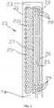
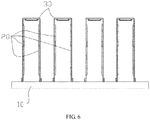
- a heat sink in an embodiment of the present invention includes a base 10 and a plurality of fins 20, where the plurality of fins 20 are spaced apart on the base 10 to form a cooling fin structure. Specifically, the plurality of fins 20 are spaced apart from each other at an equal distance.
- the base 10 is made of a thermally conductive material, such as a metal plate or a ceramic base 10.
- the base 10 includes two surfaces that are opposite to each other.
- One of the two surfaces of the base 10 is configured to get in contact with a heat emitting element in a communications product, and may be disposed, by using thermally conductive adhesive or a thermally conductive medium, between the base 10 and the heat emitting element, so that the base 10 and the heat emitting element are thermally in contact with each other.
- the other surface of the base 10 is configured to install the plurality of fins 20.
- each of the fins 20 includes a root 21 and a tip 22 that are disposed opposite to each other.
- Each of the fins 20 further includes a top 23 and a bottom 24 that are disposed opposite to each other and connected between the root 21 and the tip 22.
- the fin 20 is in a square or rectangle as a whole, and the root 21, the tip 22, the top 23, and the bottom 24 are respectively located on four sides of the fin 20.
- the root 21 is connected to the base 10.
- the fin 20 is erected on a surface of the base 10 by combining the root 21 and the base 10.
- the fin 20 and the base 10 may be perpendicular to each other, or there may be a specific tilt angle between the fin 20 and the base 10.
- a standard for setting the tilt angle is to ensure that the tip 22 far away from the base 10 reaches a temperature making a working medium in the fin 20 turn from a gas state to a liquid state.
- the fin 20 is roughly in a rectangular plate shape, the root 21 and the tip 22 are located on two opposite long sides of the rectangular plate shape, and the top 23 and the bottom 24 are located on two opposite short sides of the rectangular plate shape.
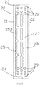
- a heated area 25, a dropping pipe 26, and a spacing strip 27 that separates the heated area 25 from the dropping pipe 26 are formed in the fin 20.
- An area represented by a dashed line box in FIG. 1 or FIG. 2 is the heated area 25.
- the root 21 is closest to a heat source, and heat is transferred from the root 21 to other parts of the fin 20; therefore, a working medium in the heated area 25 is heated and starts working first.
- the heated area 25 is located between the root 21 and the spacing strip 27.
- the dropping pipe 26 is located between the spacing strip 27 and the tip 22.
- a first passage 28 and a second passage 29 are formed between the heated area 25 and the dropping pipe 26.
- the first passage 28 is located between the spacing strip 27 and the top 23, and the second passage 29 is located between the spacing strip 27 and the bottom 24.
- a hydraulic diameter of a pipeline in the heated area 25 is less than a critical dimension, so that the working medium in the heated area 25 is heated to form a gas-liquid plug flow flowing toward the first passage 28 and flowing into the dropping pipe 26 through the first passage 28.
- a hydraulic diameter of a pipeline of the dropping pipe 26 is greater than or equal to the critical dimension, and a pressure of liquid at an intersection of the second passage 29 and the dropping pipe 26 is greater than a pressure of liquid at an intersection of the second passage 29 and the heated area 25, so that liquid in the dropping pipe 26 flows toward the heated area 25 through the second passage 29.
- the hydraulic diameter is a ratio of four times a flow cross-sectional area to a wetted perimeter.
- the critical dimension is a maximum hydraulic diameter of a pipeline that can be used when the working medium in the heated area is heated in the pipeline to form a gas-liquid plug flow. In other words, when the hydraulic diameter of the pipeline is greater than the critical dimension, the working medium heated in the pipeline cannot become in the gas-liquid plug flow state.
- a required hydraulic diameter of the pipeline varies according to different working media.
- the pipeline in the heated area 25 and the dropping pipe 26 are formed in the fin 20, the heated area 25 and the dropping pipe 26 are isolated from each other by the spacing strip 27, and the first passage 28 and the second passage 29 are disposed at two ends of the spacing strip 27, so that the heated area 25 and the dropping pipe 26 are communicated with each other.
- the base 10 is close to the heat source, the working medium in the heated area 25 is heated.
- the hydraulic diameter of the pipeline in the heated area 25 is less than the critical dimension, the working medium can form the gas-liquid plug flow after being heated. Air bubbles in the liquid push the liquid to flow toward the first passage 28 at the top 23.
- the first passage 28 is equivalent to a transverse flow gathering area at the top 23 of the fin 20.
- the first passage 28 and the second passage 29 are honeycombed. Specifically, the first passage 28 and the second passage 29 each include at least two crisscrossed pipelines.
- the pipeline in the heated area 25 includes a plurality of longitudinal pipelines that extend from the bottom 24 to the top 23, and a plurality of transverse pipelines that are communicated between the longitudinal pipelines.
- the transverse pipeline is configured to perform pressure balancing and temperature balancing of liquid and vapor.
- the longitudinal pipelines extend in a direction from the second passage 29 to the first passage 28.
- working medium circulation also exists inside the heated area 25.
- the transverse pipeline is communicated between the longitudinal pipelines in the heated area 25.
- liquid levels of the longitudinal pipelines are different in height, liquid in a longitudinal pipeline whose liquid level is relatively high flows through the transverse pipeline into a longitudinal pipeline whose liquid level is relatively low, so that a pressure and a temperature of liquid and vapor in the heated area are balanced.
- the pipelines in the heated area 25 are honeycombed, and the heated area 25 is separated by a plurality of polygonal (which may be hexagonal, octagonal, or the like) or small round cake-shaped spacing zones 251 in the heated area 25 to form the pipelines (the pipelines herein are the longitudinal passage and the transverse passage).
- a pipeline is formed between two adjacent spacing zones 251.
- the small cake-shaped spacing zones 251 are vertically arranged in two columns, and the two columns of small cake-shaped spacing zones 251 are interlaced.
- a pipeline between two spacing zones 251 in one column is exactly disposed opposite to a pipeline between two spacing zones 251 in the other column.
- the two columns of spacing zones 251 form three longitudinal pipelines.
- the longitudinal pipelines are rising pipelines.
- the longitudinal pipeline extends in a shape of a wave line.
- a side, adjacent to the heated area 25, of the spacing strip 27 is in a shape of a wave line, and a side, adjacent to the dropping pipe 26, of the spacing strip 27 is straight-lined.
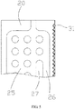
- the heated area 25 is separated by a plurality of bar-shaped spacing zones 252 in the heated area 25 to form the pipelines.
- the bar-shaped spacing zone 252 includes two straight-lined long sides, and the two long sides are connected by curved sides.
- the bar-shaped spacing zones 252 are vertically arranged in two columns, and the transverse pipeline is formed between two adjacent spacing zones 252 in one column.
- the longitudinal pipelines extend as straight-lined pipelines.
- the spacing strip 27 is also bar-shaped. A shape of the spacing strip 27 is similar to a shape of the spacing zone 252. Both the side, adjacent to the heated area 25, of the spacing strip 27 and the side, adjacent to the dropping pipe 26, of the spacing strip 27 are straight-lined.
- a range of the critical dimension is 0.5 mm to 20 mm. Selection of the critical dimension is associated with selection of the working medium.
- the pipeline in the heated area 25 of the fin 20 and the pipeline of the dropping pipe 26 are formed by using an extrusion molding technology.
- the pipeline in the heated area 25 of the fin 20 and the pipeline of the dropping pipe 26 are formed by using a blow molding technology. Compared with a cast fin 20, a fin 20 manufactured by using the extrusion molding technology or the blow molding technology is lighter and thinner, facilitating development of light and thin communications products.
- the fin 20 is plate-like.
- the fin 20 and the base 10 may be perpendicular or basically perpendicular to each other.
- the fin 20 may be a non-plate structure, and the fin 20 includes a curved surface. Specifically, a curving direction of the curved surface extends between the root 21 and the tip 22, and the fin 20 vertically extends between the top 23 and the bottom 24.
- the fin 20 has a partially-cylindrical surface or a semi-cylindrical surface, and a design of the curved surface is conducive to increasing a windward area within a same size between the root 21 and the tip 22, thereby improving a heat dissipation capability.
- Heat of the fin 20 is usually dissipated through air cooling in a product, and airflow flows over the fin 20 to take away the heat. Because the tip 22 is far away from the heat source, a temperature of the tip 22 is lower than that of the root 21. In other words, temperatures from the root 21 to the tip 22 are distributed in a descending manner.
- the curved surface is curved and extends in a smooth arc shape.
- the extension in the smooth arc shape does not affect mutual communication between the pipelines in the heated area 25, and the transverse pipeline in the heated area 25 may also extend in an arc shape.
- the longitudinal pipelines in the heated area 25 are not affected by the curved surface and still maintain a vertical tube shape, because the curving direction of the curved surface extends between the root 21 and the tip 22.
- the heat sink further includes a connecting piece 30, and the connecting piece 30 is connected between tips 22 of two adjacent fins 20.
- the two adjacent fins 20 are connected to each other by disposing the connecting piece 30. In this way, efficiency can be improved both in a process of making the fins 20 and in a process of installing the fins 20 onto the base 10.
- a plurality of holes 31 are disposed on the connecting piece 30.
- the holes 31 may be of a shutter structure, or openings may be directly disposed on the connecting piece 30.
- the holes 31 can be disposed not only to help decrease a mass of the heat sink, but also help improve a heat dissipation capability, because the holes 31 make space between the fins 20 be communicated with the outside.
- a quantity of fins 20 is twice a quantity of connecting pieces 30.
- a passage is disposed between two adjacent fins 20, and two adjacent connecting pieces 30 are isolated by the passage.
- two fins 20 and one connecting piece 30 together form a U-shaped heat dissipation unit
- the heat sink includes a plurality of heat dissipation units, and adjacent heat dissipation units are kept separated through the passage.
- pipelines of the fins 20 of the heat dissipation unit are formed on an inner side.
- each fin 20 includes two faces.
- Pipelines are disposed on one face, and the other face is a plane.
- pipelines are disposed on faces that are of one fin 20 and the other fin 20 and that are opposite to each other, and the other face of each fin 20 is a plane.
- Such a design makes the pipelines of the heat sink be concealed in an inner side of space that is formed by a pair of fins 20, the connecting piece 30, and the base 10, so that an appearance of the heat sink is smooth and flat.
- the connecting piece 30 and the two adjacent fins 20 form such an integrated structure.
- the integrated structure can be more easily made.
- pipeline areas of two independent fins 20 may be directly made by using the blow molding technology on one plate.
- the pipeline areas of the two independent fins 20 are spaced apart from each other by using the connecting piece 30, and then the two fins 20 and the connecting piece 30 are bent by using a bending technology, to form a U-shaped heat dissipation unit.
- a detached structure may alternatively be used between the connecting piece 30 and the two adjacent fins 20, to install the connecting piece 30 onto the fins 20 through structural cooperation (for example, by using a connection manner such as welding, gluing, or screw fastening).
- the connecting piece 30 is connected to the fins 20, to ensure structural stability of the fins 20.
- the heat sink includes a cover plate.
- a position of the cover plate is the same as a position of the connecting piece 30.
- the connecting piece 30 is replaced with the cover plate structure.
- the connecting piece 30 may be considered as a strip structure between two adjacent fins.
- the cover plate in this implementation may be considered as an overall plate structure.
- the cover plate covers a side of tips 22 of all fins 20, and the cover plate is combined with the tips 22 of the fins 20.
- the cover plate and the tips 22 of the fins 20 may be fastened to each other in a welding or riveting manner, or in a sliding-fit detachable connection manner.
- a slot may be disposed on a surface of the cover plate, and the tip 22 is nested into the slot and cooperates with the slot, so as to implement cooperation between the cover plate and the fin 20.
- a structure of the cover plate is similar to a structure of the base 10. Differences between the two structures include the following: No electronic element is disposed on the cover plate, and the cover plate is configured only to fasten the fin and assist in heat dissipation; in addition to the fin 20 fastened to the base, an electronic element is also disposed on the base 10.
- the base 10 may be a circuit board on which an electronic element and a connection interface are disposed, and the heat emitting element is disposed on a side, which backs on a side of the fin 20, of the base 10.
- the cover plate may be disposed in parallel to the base 10.
- a detachable connection structure is used between the root 21 of the fin 20 and the base 10.
- a slot is disposed on the base 10, and the root 21 is nested into the slot to cooperate with the slot, so as to implement fastening between the base 10 and the fin 20.
- the root 21 of the fin 20 and the base 10 are fastened and connected to each other in a welding or gluing manner.
- the present invention further provides a communications product, including the heat sink and a heat emitting element.
- a side, which backs on a side of the fin 20, of the base 10 of the heat sink is connected to the heat emitting element in a thermally conductive manner.
- the heat emitting element and the base 10 may be fit by using a thermally conductive medium, or may be directly in contact with each other.
- a position of the heat emitting element on the base 10 is exactly opposite to a middle area between the top 23 and the bottom 24 of the fin 20.
- a size of the pipeline in the heated area of the heat sink is restricted, that is, the hydraulic diameter of the pipeline in the heated area is less than the critical dimension, so that the working medium in the heated area is heated to form the gas-liquid plug flow.
- a size of a pipeline of the dropping pipe is restricted.
- the hydraulic diameter of the dropping pipe is greater than or equal to the critical dimension.
- the heat sink provided in the present invention can implement a same amount of dissipated heat, with only a relatively small size and volume.
Landscapes
- Engineering & Computer Science (AREA)
- Microelectronics & Electronic Packaging (AREA)
- Physics & Mathematics (AREA)
- Thermal Sciences (AREA)
- Cooling Or The Like Of Electrical Apparatus (AREA)
- Gears, Cams (AREA)
- Heat-Exchange Devices With Radiators And Conduit Assemblies (AREA)
Applications Claiming Priority (2)
| Application Number | Priority Date | Filing Date | Title |
|---|---|---|---|
| CN201611260377.6A CN106686947B (zh) | 2016-12-30 | 2016-12-30 | 散热器及通信产品 |
| PCT/CN2017/118641 WO2018121533A1 (fr) | 2016-12-30 | 2017-12-26 | Dissipateur thermique et produit de communication |
Publications (3)
| Publication Number | Publication Date |
|---|---|
| EP3550947A1 true EP3550947A1 (fr) | 2019-10-09 |
| EP3550947A4 EP3550947A4 (fr) | 2020-01-01 |
| EP3550947B1 EP3550947B1 (fr) | 2021-04-28 |
Family
ID=58873566
Family Applications (1)
| Application Number | Title | Priority Date | Filing Date |
|---|---|---|---|
| EP17887331.1A Active EP3550947B1 (fr) | 2016-12-30 | 2017-12-26 | Dissipateur thermique et produit de communication |
Country Status (4)
| Country | Link |
|---|---|
| US (2) | US10820448B2 (fr) |
| EP (1) | EP3550947B1 (fr) |
| CN (1) | CN106686947B (fr) |
| WO (1) | WO2018121533A1 (fr) |
Cited By (2)
| Publication number | Priority date | Publication date | Assignee | Title |
|---|---|---|---|---|
| EP3848662A1 (fr) * | 2020-01-13 | 2021-07-14 | Cooler Master Co., Ltd. | Ailette d'échangeur de chaleur et son procédé de fabrication |
| EP3859261A1 (fr) * | 2020-01-29 | 2021-08-04 | Cooler Master Co., Ltd. | Ailette d'échangeur de chaleur et son procédé de fabrication |
Families Citing this family (15)
| Publication number | Priority date | Publication date | Assignee | Title |
|---|---|---|---|---|
| CN106686947B (zh) | 2016-12-30 | 2018-11-09 | 华为机器有限公司 | 散热器及通信产品 |
| KR102173228B1 (ko) * | 2019-01-04 | 2020-11-03 | 한국과학기술원 | 연성 평판 진동형 히트파이프 및 이의 제작 방법 |
| TWI699508B (zh) * | 2019-06-11 | 2020-07-21 | 大陸商深圳興奇宏科技有限公司 | 流道型二相流散熱器 |
| CN112243333B (zh) * | 2019-07-17 | 2022-02-25 | 华为技术有限公司 | 一种齿片、散热器和通信设备 |
| CN110868838A (zh) * | 2019-10-12 | 2020-03-06 | 太仓市华盈电子材料有限公司 | 一种均温板散热器 |
| CN111473670A (zh) * | 2020-04-09 | 2020-07-31 | 浙江嘉熙科技有限公司 | 热超导传热板及散热器 |
| CN111609743A (zh) * | 2020-04-27 | 2020-09-01 | 浙江嘉熙科技有限公司 | 热超导散热板、散热器及5g基站设备 |
| WO2021217789A1 (fr) * | 2020-04-27 | 2021-11-04 | 浙江嘉熙科技有限公司 | Plaque de dissipation de la chaleur à supraconduction de la chaleur, dispositif de dissipation de la chaleur et appareil de station de base 5g |
| CN113883947A (zh) * | 2020-07-01 | 2022-01-04 | 讯凯国际股份有限公司 | 热交换器鳍片与用于制造热交换器鳍片的方法 |
| US12453039B2 (en) * | 2021-01-04 | 2025-10-21 | Telefonaktiebolaget Lm Ericsson (Publ) | Heatsink and communication device having the heatsink |
| IT202100004793A1 (it) * | 2021-03-02 | 2022-09-02 | Wieland Provides SRL | Scambiatore di calore a microcanali |
| CN113757846B (zh) * | 2021-08-24 | 2023-06-16 | 华为数字能源技术有限公司 | 复合制冷系统和数据中心 |
| CN117355082A (zh) * | 2022-06-29 | 2024-01-05 | 中兴智能科技南京有限公司 | 一种导热板、散热装置和电子设备 |
| EP4387405A1 (fr) | 2022-12-14 | 2024-06-19 | Huawei Technologies Co., Ltd. | Appareil pour transférer de la chaleur d'une source de chaleur à l'air |
| CN119983873B (zh) * | 2025-02-28 | 2026-03-03 | 深圳三星通信技术研究有限公司 | 一种相变散热器 |
Family Cites Families (25)
| Publication number | Priority date | Publication date | Assignee | Title |
|---|---|---|---|---|
| US4125122A (en) * | 1975-08-11 | 1978-11-14 | Stachurski John Z O | Direct energy conversion device |
| US5170319A (en) * | 1990-06-04 | 1992-12-08 | International Business Machines Corporation | Enhanced multichip module cooling with thermally optimized pistons and closely coupled convective cooling channels |
| US6496375B2 (en) * | 2001-04-30 | 2002-12-17 | Hewlett-Packard Company | Cooling arrangement for high density packaging of electronic components |
| US7286355B2 (en) * | 2002-09-11 | 2007-10-23 | Kioan Cheon | Cooling system for electronic devices |
| US20080062652A1 (en) * | 2006-09-07 | 2008-03-13 | Wayne Lieberman | Vapor heat spreader |
| US7965508B2 (en) * | 2007-03-27 | 2011-06-21 | Denso Corporation | Cooling device for electronic component and power converter equipped with the same |
| US20090002951A1 (en) * | 2007-06-29 | 2009-01-01 | Qimonda Ag | System having a heat transfer apparatus |
| US8919426B2 (en) * | 2007-10-22 | 2014-12-30 | The Peregrine Falcon Corporation | Micro-channel pulsating heat pipe |
| US7755897B2 (en) * | 2007-12-27 | 2010-07-13 | Fu Zhun Precision Industry (Shen Zhen) Co., Ltd. | Memory module assembly with heat dissipation device |
| US9157687B2 (en) * | 2007-12-28 | 2015-10-13 | Qcip Holdings, Llc | Heat pipes incorporating microchannel heat exchangers |
| CN101216209A (zh) * | 2008-01-18 | 2008-07-09 | 上海精励汽车科技有限公司 | 汽车空调平行流蒸发器 |
| US9342121B2 (en) * | 2008-05-06 | 2016-05-17 | International Business Machines Corporatoin | Cooling system for electronic components |
| WO2010014878A1 (fr) * | 2008-07-31 | 2010-02-04 | Georgia Tech Research Corporation | Système d'échelle microscopique de transfert de chaleur ou de transfert de chaleur et de masse |
| US8720536B2 (en) * | 2009-09-04 | 2014-05-13 | Modine Manufacturing Company | Heat exchanger having flow diverter |
| CN102130080B (zh) * | 2010-11-11 | 2012-12-12 | 华为技术有限公司 | 一种散热装置 |
| EP2722877A4 (fr) * | 2011-06-15 | 2015-06-17 | Toyota Motor Co Ltd | Structure de refroidissement pour élément semi-conducteur |
| US20130005372A1 (en) * | 2011-06-29 | 2013-01-03 | Rosemount Inc. | Integral thermoelectric generator for wireless devices |
| KR20130111035A (ko) * | 2012-03-30 | 2013-10-10 | 엘에스산전 주식회사 | 진동세관형 히트파이프 방열핀을 접착한 히트싱크 |
| EP2677261B1 (fr) * | 2012-06-20 | 2018-10-10 | ABB Schweiz AG | Système de refroidissement biphasé pour composants électroniques |
| US9497888B2 (en) * | 2013-02-27 | 2016-11-15 | International Business Machines Corporation | Thermal transfer structure(s) and attachment mechanism(s) facilitating cooling of electronics card(s) |
| EP2876400B1 (fr) | 2013-11-20 | 2016-10-05 | ABB Technology Oy | Élément de refroidissement |
| CN107078659A (zh) * | 2014-11-13 | 2017-08-18 | 日立汽车系统株式会社 | 电力转换装置 |
| CN205104482U (zh) | 2015-07-03 | 2016-03-23 | 浙江嘉熙光电设备制造有限公司 | 热超导散热器 |
| CN106686947B (zh) * | 2016-12-30 | 2018-11-09 | 华为机器有限公司 | 散热器及通信产品 |
| US10602638B2 (en) * | 2018-03-01 | 2020-03-24 | Dell Products L.P. | System and method of transferring energy |
-
2016
- 2016-12-30 CN CN201611260377.6A patent/CN106686947B/zh active Active
-
2017
- 2017-12-26 EP EP17887331.1A patent/EP3550947B1/fr active Active
- 2017-12-26 WO PCT/CN2017/118641 patent/WO2018121533A1/fr not_active Ceased
-
2019
- 2019-07-01 US US16/458,711 patent/US10820448B2/en active Active
-
2020
- 2020-10-23 US US17/079,408 patent/US11330737B2/en active Active
Cited By (2)
| Publication number | Priority date | Publication date | Assignee | Title |
|---|---|---|---|---|
| EP3848662A1 (fr) * | 2020-01-13 | 2021-07-14 | Cooler Master Co., Ltd. | Ailette d'échangeur de chaleur et son procédé de fabrication |
| EP3859261A1 (fr) * | 2020-01-29 | 2021-08-04 | Cooler Master Co., Ltd. | Ailette d'échangeur de chaleur et son procédé de fabrication |
Also Published As
| Publication number | Publication date |
|---|---|
| CN106686947B (zh) | 2018-11-09 |
| EP3550947B1 (fr) | 2021-04-28 |
| US20190327857A1 (en) | 2019-10-24 |
| US20210045263A1 (en) | 2021-02-11 |
| US11330737B2 (en) | 2022-05-10 |
| WO2018121533A1 (fr) | 2018-07-05 |
| US10820448B2 (en) | 2020-10-27 |
| CN106686947A (zh) | 2017-05-17 |
| EP3550947A4 (fr) | 2020-01-01 |
Similar Documents
| Publication | Publication Date | Title |
|---|---|---|
| US11330737B2 (en) | Heat sink and communications product | |
| JP3206206U (ja) | 気液分離構造を有するベイパーチャンバー | |
| US9273909B2 (en) | Heat pipe structure, and thermal module and electronic device using same | |
| US8757247B2 (en) | Heat pipe structure | |
| CN106376214B (zh) | 薄型均温板 | |
| JP5342392B2 (ja) | 冷却装置 | |
| CN106033749B (zh) | 并联式平行微通道多芯片散热器 | |
| TWI765775B (zh) | 散熱裝置 | |
| US20130175021A1 (en) | Servo amplifier with heat sink having two sets of heat-releasing plates perpendicular to each other | |
| EP2541138B1 (fr) | Appareil d'éclairage à diodes électroluminescentes | |
| KR20130111035A (ko) | 진동세관형 히트파이프 방열핀을 접착한 히트싱크 | |
| CN101840257A (zh) | 散热模组及其固定装置 | |
| CN102042777A (zh) | 平板式热管 | |
| KR20150075122A (ko) | 열전소자가 구비된 열교환기 | |
| CN109945698A (zh) | 一种协同增强换热的微通道换热器结构设计方法及装置 | |
| CN100414692C (zh) | 热管散热装置 | |
| CN110679207B (zh) | 冷却装置 | |
| CN220733292U (zh) | 一种翼型均温板 | |
| CN201039638Y (zh) | 散热器结构 | |
| CN104329650B (zh) | 采用金属‑聚合物‑热管复合的led台灯的散热结构 | |
| RU83684U1 (ru) | Радиатор (варианты) | |
| CN102444876A (zh) | 一种紊流散热器 | |
| KR20090000383U (ko) | 방열판 | |
| CN102263355B (zh) | 气体或固体激光器散热装置 | |
| CN214896514U (zh) | 一种cpu散热器 |
Legal Events
| Date | Code | Title | Description |
|---|---|---|---|
| STAA | Information on the status of an ep patent application or granted ep patent |
Free format text: STATUS: THE INTERNATIONAL PUBLICATION HAS BEEN MADE |
|
| PUAI | Public reference made under article 153(3) epc to a published international application that has entered the european phase |
Free format text: ORIGINAL CODE: 0009012 |
|
| STAA | Information on the status of an ep patent application or granted ep patent |
Free format text: STATUS: REQUEST FOR EXAMINATION WAS MADE |
|
| 17P | Request for examination filed |
Effective date: 20190705 |
|
| AK | Designated contracting states |
Kind code of ref document: A1 Designated state(s): AL AT BE BG CH CY CZ DE DK EE ES FI FR GB GR HR HU IE IS IT LI LT LU LV MC MK MT NL NO PL PT RO RS SE SI SK SM TR |
|
| AX | Request for extension of the european patent |
Extension state: BA ME |
|
| A4 | Supplementary search report drawn up and despatched |
Effective date: 20191128 |
|
| RIC1 | Information provided on ipc code assigned before grant |
Ipc: H01L 23/36 20060101ALI20191122BHEP Ipc: H05K 7/20 20060101AFI20191122BHEP Ipc: F28D 15/00 20060101ALI20191122BHEP Ipc: F28D 15/02 20060101ALI20191122BHEP |
|
| DAV | Request for validation of the european patent (deleted) | ||
| DAX | Request for extension of the european patent (deleted) | ||
| GRAP | Despatch of communication of intention to grant a patent |
Free format text: ORIGINAL CODE: EPIDOSNIGR1 |
|
| STAA | Information on the status of an ep patent application or granted ep patent |
Free format text: STATUS: GRANT OF PATENT IS INTENDED |
|
| RIC1 | Information provided on ipc code assigned before grant |
Ipc: F28D 15/00 20060101ALI20201026BHEP Ipc: H01L 23/36 20060101ALI20201026BHEP Ipc: H05K 7/20 20060101AFI20201026BHEP Ipc: F28D 15/02 20060101ALI20201026BHEP Ipc: H01L 23/427 20060101ALI20201026BHEP |
|
| INTG | Intention to grant announced |
Effective date: 20201109 |
|
| GRAS | Grant fee paid |
Free format text: ORIGINAL CODE: EPIDOSNIGR3 |
|
| GRAA | (expected) grant |
Free format text: ORIGINAL CODE: 0009210 |
|
| STAA | Information on the status of an ep patent application or granted ep patent |
Free format text: STATUS: THE PATENT HAS BEEN GRANTED |
|
| AK | Designated contracting states |
Kind code of ref document: B1 Designated state(s): AL AT BE BG CH CY CZ DE DK EE ES FI FR GB GR HR HU IE IS IT LI LT LU LV MC MK MT NL NO PL PT RO RS SE SI SK SM TR |
|
| REG | Reference to a national code |
Ref country code: GB Ref legal event code: FG4D |
|
| REG | Reference to a national code |
Ref country code: CH Ref legal event code: EP |
|
| REG | Reference to a national code |
Ref country code: AT Ref legal event code: REF Ref document number: 1388631 Country of ref document: AT Kind code of ref document: T Effective date: 20210515 |
|
| REG | Reference to a national code |
Ref country code: DE Ref legal event code: R096 Ref document number: 602017037856 Country of ref document: DE |
|
| REG | Reference to a national code |
Ref country code: IE Ref legal event code: FG4D |
|
| REG | Reference to a national code |
Ref country code: LT Ref legal event code: MG9D |
|
| REG | Reference to a national code |
Ref country code: AT Ref legal event code: MK05 Ref document number: 1388631 Country of ref document: AT Kind code of ref document: T Effective date: 20210428 |
|
| PG25 | Lapsed in a contracting state [announced via postgrant information from national office to epo] |
Ref country code: AT Free format text: LAPSE BECAUSE OF FAILURE TO SUBMIT A TRANSLATION OF THE DESCRIPTION OR TO PAY THE FEE WITHIN THE PRESCRIBED TIME-LIMIT Effective date: 20210428 Ref country code: BG Free format text: LAPSE BECAUSE OF FAILURE TO SUBMIT A TRANSLATION OF THE DESCRIPTION OR TO PAY THE FEE WITHIN THE PRESCRIBED TIME-LIMIT Effective date: 20210728 Ref country code: HR Free format text: LAPSE BECAUSE OF FAILURE TO SUBMIT A TRANSLATION OF THE DESCRIPTION OR TO PAY THE FEE WITHIN THE PRESCRIBED TIME-LIMIT Effective date: 20210428 Ref country code: NL Free format text: LAPSE BECAUSE OF FAILURE TO SUBMIT A TRANSLATION OF THE DESCRIPTION OR TO PAY THE FEE WITHIN THE PRESCRIBED TIME-LIMIT Effective date: 20210428 Ref country code: LT Free format text: LAPSE BECAUSE OF FAILURE TO SUBMIT A TRANSLATION OF THE DESCRIPTION OR TO PAY THE FEE WITHIN THE PRESCRIBED TIME-LIMIT Effective date: 20210428 Ref country code: FI Free format text: LAPSE BECAUSE OF FAILURE TO SUBMIT A TRANSLATION OF THE DESCRIPTION OR TO PAY THE FEE WITHIN THE PRESCRIBED TIME-LIMIT Effective date: 20210428 |
|
| PG25 | Lapsed in a contracting state [announced via postgrant information from national office to epo] |
Ref country code: IS Free format text: LAPSE BECAUSE OF FAILURE TO SUBMIT A TRANSLATION OF THE DESCRIPTION OR TO PAY THE FEE WITHIN THE PRESCRIBED TIME-LIMIT Effective date: 20210828 Ref country code: GR Free format text: LAPSE BECAUSE OF FAILURE TO SUBMIT A TRANSLATION OF THE DESCRIPTION OR TO PAY THE FEE WITHIN THE PRESCRIBED TIME-LIMIT Effective date: 20210729 Ref country code: LV Free format text: LAPSE BECAUSE OF FAILURE TO SUBMIT A TRANSLATION OF THE DESCRIPTION OR TO PAY THE FEE WITHIN THE PRESCRIBED TIME-LIMIT Effective date: 20210428 Ref country code: PT Free format text: LAPSE BECAUSE OF FAILURE TO SUBMIT A TRANSLATION OF THE DESCRIPTION OR TO PAY THE FEE WITHIN THE PRESCRIBED TIME-LIMIT Effective date: 20210830 Ref country code: PL Free format text: LAPSE BECAUSE OF FAILURE TO SUBMIT A TRANSLATION OF THE DESCRIPTION OR TO PAY THE FEE WITHIN THE PRESCRIBED TIME-LIMIT Effective date: 20210428 Ref country code: NO Free format text: LAPSE BECAUSE OF FAILURE TO SUBMIT A TRANSLATION OF THE DESCRIPTION OR TO PAY THE FEE WITHIN THE PRESCRIBED TIME-LIMIT Effective date: 20210728 Ref country code: RS Free format text: LAPSE BECAUSE OF FAILURE TO SUBMIT A TRANSLATION OF THE DESCRIPTION OR TO PAY THE FEE WITHIN THE PRESCRIBED TIME-LIMIT Effective date: 20210428 Ref country code: SE Free format text: LAPSE BECAUSE OF FAILURE TO SUBMIT A TRANSLATION OF THE DESCRIPTION OR TO PAY THE FEE WITHIN THE PRESCRIBED TIME-LIMIT Effective date: 20210428 |
|
| REG | Reference to a national code |
Ref country code: NL Ref legal event code: MP Effective date: 20210428 |
|
| PG25 | Lapsed in a contracting state [announced via postgrant information from national office to epo] |
Ref country code: RO Free format text: LAPSE BECAUSE OF FAILURE TO SUBMIT A TRANSLATION OF THE DESCRIPTION OR TO PAY THE FEE WITHIN THE PRESCRIBED TIME-LIMIT Effective date: 20210428 Ref country code: DK Free format text: LAPSE BECAUSE OF FAILURE TO SUBMIT A TRANSLATION OF THE DESCRIPTION OR TO PAY THE FEE WITHIN THE PRESCRIBED TIME-LIMIT Effective date: 20210428 Ref country code: CZ Free format text: LAPSE BECAUSE OF FAILURE TO SUBMIT A TRANSLATION OF THE DESCRIPTION OR TO PAY THE FEE WITHIN THE PRESCRIBED TIME-LIMIT Effective date: 20210428 Ref country code: SM Free format text: LAPSE BECAUSE OF FAILURE TO SUBMIT A TRANSLATION OF THE DESCRIPTION OR TO PAY THE FEE WITHIN THE PRESCRIBED TIME-LIMIT Effective date: 20210428 Ref country code: SK Free format text: LAPSE BECAUSE OF FAILURE TO SUBMIT A TRANSLATION OF THE DESCRIPTION OR TO PAY THE FEE WITHIN THE PRESCRIBED TIME-LIMIT Effective date: 20210428 Ref country code: EE Free format text: LAPSE BECAUSE OF FAILURE TO SUBMIT A TRANSLATION OF THE DESCRIPTION OR TO PAY THE FEE WITHIN THE PRESCRIBED TIME-LIMIT Effective date: 20210428 Ref country code: ES Free format text: LAPSE BECAUSE OF FAILURE TO SUBMIT A TRANSLATION OF THE DESCRIPTION OR TO PAY THE FEE WITHIN THE PRESCRIBED TIME-LIMIT Effective date: 20210428 |
|
| REG | Reference to a national code |
Ref country code: DE Ref legal event code: R097 Ref document number: 602017037856 Country of ref document: DE |
|
| PLBE | No opposition filed within time limit |
Free format text: ORIGINAL CODE: 0009261 |
|
| STAA | Information on the status of an ep patent application or granted ep patent |
Free format text: STATUS: NO OPPOSITION FILED WITHIN TIME LIMIT |
|
| 26N | No opposition filed |
Effective date: 20220131 |
|
| PG25 | Lapsed in a contracting state [announced via postgrant information from national office to epo] |
Ref country code: IS Free format text: LAPSE BECAUSE OF FAILURE TO SUBMIT A TRANSLATION OF THE DESCRIPTION OR TO PAY THE FEE WITHIN THE PRESCRIBED TIME-LIMIT Effective date: 20210828 Ref country code: AL Free format text: LAPSE BECAUSE OF FAILURE TO SUBMIT A TRANSLATION OF THE DESCRIPTION OR TO PAY THE FEE WITHIN THE PRESCRIBED TIME-LIMIT Effective date: 20210428 |
|
| PG25 | Lapsed in a contracting state [announced via postgrant information from national office to epo] |
Ref country code: MC Free format text: LAPSE BECAUSE OF FAILURE TO SUBMIT A TRANSLATION OF THE DESCRIPTION OR TO PAY THE FEE WITHIN THE PRESCRIBED TIME-LIMIT Effective date: 20210428 Ref country code: IT Free format text: LAPSE BECAUSE OF FAILURE TO SUBMIT A TRANSLATION OF THE DESCRIPTION OR TO PAY THE FEE WITHIN THE PRESCRIBED TIME-LIMIT Effective date: 20210428 |
|
| REG | Reference to a national code |
Ref country code: CH Ref legal event code: PL |
|
| REG | Reference to a national code |
Ref country code: BE Ref legal event code: MM Effective date: 20211231 |
|
| PG25 | Lapsed in a contracting state [announced via postgrant information from national office to epo] |
Ref country code: LU Free format text: LAPSE BECAUSE OF NON-PAYMENT OF DUE FEES Effective date: 20211226 Ref country code: IE Free format text: LAPSE BECAUSE OF NON-PAYMENT OF DUE FEES Effective date: 20211226 |
|
| PG25 | Lapsed in a contracting state [announced via postgrant information from national office to epo] |
Ref country code: BE Free format text: LAPSE BECAUSE OF NON-PAYMENT OF DUE FEES Effective date: 20211231 |
|
| PG25 | Lapsed in a contracting state [announced via postgrant information from national office to epo] |
Ref country code: LI Free format text: LAPSE BECAUSE OF NON-PAYMENT OF DUE FEES Effective date: 20211231 Ref country code: CH Free format text: LAPSE BECAUSE OF NON-PAYMENT OF DUE FEES Effective date: 20211231 |
|
| P01 | Opt-out of the competence of the unified patent court (upc) registered |
Effective date: 20230524 |
|
| PG25 | Lapsed in a contracting state [announced via postgrant information from national office to epo] |
Ref country code: CY Free format text: LAPSE BECAUSE OF FAILURE TO SUBMIT A TRANSLATION OF THE DESCRIPTION OR TO PAY THE FEE WITHIN THE PRESCRIBED TIME-LIMIT Effective date: 20210428 |
|
| PG25 | Lapsed in a contracting state [announced via postgrant information from national office to epo] |
Ref country code: HU Free format text: LAPSE BECAUSE OF FAILURE TO SUBMIT A TRANSLATION OF THE DESCRIPTION OR TO PAY THE FEE WITHIN THE PRESCRIBED TIME-LIMIT; INVALID AB INITIO Effective date: 20171226 |
|
| PG25 | Lapsed in a contracting state [announced via postgrant information from national office to epo] |
Ref country code: MK Free format text: LAPSE BECAUSE OF FAILURE TO SUBMIT A TRANSLATION OF THE DESCRIPTION OR TO PAY THE FEE WITHIN THE PRESCRIBED TIME-LIMIT Effective date: 20210428 |
|
| PG25 | Lapsed in a contracting state [announced via postgrant information from national office to epo] |
Ref country code: TR Free format text: LAPSE BECAUSE OF FAILURE TO SUBMIT A TRANSLATION OF THE DESCRIPTION OR TO PAY THE FEE WITHIN THE PRESCRIBED TIME-LIMIT Effective date: 20210428 |
|
| PG25 | Lapsed in a contracting state [announced via postgrant information from national office to epo] |
Ref country code: MT Free format text: LAPSE BECAUSE OF FAILURE TO SUBMIT A TRANSLATION OF THE DESCRIPTION OR TO PAY THE FEE WITHIN THE PRESCRIBED TIME-LIMIT Effective date: 20210428 |
|
| PGFP | Annual fee paid to national office [announced via postgrant information from national office to epo] |
Ref country code: DE Payment date: 20251104 Year of fee payment: 9 |
|
| PGFP | Annual fee paid to national office [announced via postgrant information from national office to epo] |
Ref country code: GB Payment date: 20251114 Year of fee payment: 9 |
|
| PGFP | Annual fee paid to national office [announced via postgrant information from national office to epo] |
Ref country code: FR Payment date: 20251110 Year of fee payment: 9 |