EP3551103B1 - Dispositif d'introduction ayant des capacités d'extension - Google Patents
Dispositif d'introduction ayant des capacités d'extension Download PDFInfo
- Publication number
- EP3551103B1 EP3551103B1 EP17832615.3A EP17832615A EP3551103B1 EP 3551103 B1 EP3551103 B1 EP 3551103B1 EP 17832615 A EP17832615 A EP 17832615A EP 3551103 B1 EP3551103 B1 EP 3551103B1
- Authority
- EP
- European Patent Office
- Prior art keywords
- liner
- introducer
- spine
- examples
- rib members
- Prior art date
- Legal status (The legal status is an assumption and is not a legal conclusion. Google has not performed a legal analysis and makes no representation as to the accuracy of the status listed.)
- Active
Links
Images





Classifications
-
- A—HUMAN NECESSITIES
- A61—MEDICAL OR VETERINARY SCIENCE; HYGIENE
- A61B—DIAGNOSIS; SURGERY; IDENTIFICATION
- A61B17/00—Surgical instruments, devices or methods
- A61B17/34—Trocars; Puncturing needles
- A61B17/3417—Details of tips or shafts, e.g. grooves, expandable, bendable; Multiple coaxial sliding cannulas, e.g. for dilating
- A61B17/3421—Cannulas
- A61B17/3423—Access ports, e.g. toroid shape introducers for instruments or hands
-
- A—HUMAN NECESSITIES
- A61—MEDICAL OR VETERINARY SCIENCE; HYGIENE
- A61B—DIAGNOSIS; SURGERY; IDENTIFICATION
- A61B17/00—Surgical instruments, devices or methods
- A61B17/34—Trocars; Puncturing needles
- A61B17/3417—Details of tips or shafts, e.g. grooves, expandable, bendable; Multiple coaxial sliding cannulas, e.g. for dilating
- A61B17/3421—Cannulas
- A61B17/3431—Cannulas being collapsible, e.g. made of thin flexible material
-
- A—HUMAN NECESSITIES
- A61—MEDICAL OR VETERINARY SCIENCE; HYGIENE
- A61B—DIAGNOSIS; SURGERY; IDENTIFICATION
- A61B17/00—Surgical instruments, devices or methods
- A61B17/34—Trocars; Puncturing needles
- A61B17/3417—Details of tips or shafts, e.g. grooves, expandable, bendable; Multiple coaxial sliding cannulas, e.g. for dilating
- A61B17/3421—Cannulas
- A61B17/3439—Cannulas with means for changing the inner diameter of the cannula, e.g. expandable
-
- A—HUMAN NECESSITIES
- A61—MEDICAL OR VETERINARY SCIENCE; HYGIENE
- A61M—DEVICES FOR INTRODUCING MEDIA INTO, OR ONTO, THE BODY; DEVICES FOR TRANSDUCING BODY MEDIA OR FOR TAKING MEDIA FROM THE BODY; DEVICES FOR PRODUCING OR ENDING SLEEP OR STUPOR
- A61M25/00—Catheters; Hollow probes
- A61M25/0021—Catheters; Hollow probes characterised by the form of the tubing
- A61M25/0023—Catheters; Hollow probes characterised by the form of the tubing by the form of the lumen, e.g. cross-section, variable diameter
-
- A—HUMAN NECESSITIES
- A61—MEDICAL OR VETERINARY SCIENCE; HYGIENE
- A61B—DIAGNOSIS; SURGERY; IDENTIFICATION
- A61B17/00—Surgical instruments, devices or methods
- A61B17/34—Trocars; Puncturing needles
- A61B17/3498—Valves therefor, e.g. flapper valves, slide valves
-
- A—HUMAN NECESSITIES
- A61—MEDICAL OR VETERINARY SCIENCE; HYGIENE
- A61B—DIAGNOSIS; SURGERY; IDENTIFICATION
- A61B17/00—Surgical instruments, devices or methods
- A61B17/34—Trocars; Puncturing needles
- A61B17/3417—Details of tips or shafts, e.g. grooves, expandable, bendable; Multiple coaxial sliding cannulas, e.g. for dilating
- A61B2017/3454—Details of tips
-
- A—HUMAN NECESSITIES
- A61—MEDICAL OR VETERINARY SCIENCE; HYGIENE
- A61B—DIAGNOSIS; SURGERY; IDENTIFICATION
- A61B90/00—Instruments, implements or accessories specially adapted for surgery or diagnosis and not covered by any of the groups A61B1/00 - A61B50/00, e.g. for luxation treatment or for protecting wound edges
- A61B90/39—Markers, e.g. radio-opaque or breast lesions markers
- A61B2090/3966—Radiopaque markers visible in an X-ray image
-
- A—HUMAN NECESSITIES
- A61—MEDICAL OR VETERINARY SCIENCE; HYGIENE
- A61M—DEVICES FOR INTRODUCING MEDIA INTO, OR ONTO, THE BODY; DEVICES FOR TRANSDUCING BODY MEDIA OR FOR TAKING MEDIA FROM THE BODY; DEVICES FOR PRODUCING OR ENDING SLEEP OR STUPOR
- A61M25/00—Catheters; Hollow probes
- A61M25/0021—Catheters; Hollow probes characterised by the form of the tubing
- A61M25/0023—Catheters; Hollow probes characterised by the form of the tubing by the form of the lumen, e.g. cross-section, variable diameter
- A61M2025/0024—Expandable catheters or sheaths
-
- A—HUMAN NECESSITIES
- A61—MEDICAL OR VETERINARY SCIENCE; HYGIENE
- A61M—DEVICES FOR INTRODUCING MEDIA INTO, OR ONTO, THE BODY; DEVICES FOR TRANSDUCING BODY MEDIA OR FOR TAKING MEDIA FROM THE BODY; DEVICES FOR PRODUCING OR ENDING SLEEP OR STUPOR
- A61M25/00—Catheters; Hollow probes
- A61M25/0009—Making of catheters or other medical or surgical tubes
-
- A—HUMAN NECESSITIES
- A61—MEDICAL OR VETERINARY SCIENCE; HYGIENE
- A61M—DEVICES FOR INTRODUCING MEDIA INTO, OR ONTO, THE BODY; DEVICES FOR TRANSDUCING BODY MEDIA OR FOR TAKING MEDIA FROM THE BODY; DEVICES FOR PRODUCING OR ENDING SLEEP OR STUPOR
- A61M25/00—Catheters; Hollow probes
- A61M25/0043—Catheters; Hollow probes characterised by structural features
- A61M25/0045—Catheters; Hollow probes characterised by structural features multi-layered, e.g. coated
-
- A—HUMAN NECESSITIES
- A61—MEDICAL OR VETERINARY SCIENCE; HYGIENE
- A61M—DEVICES FOR INTRODUCING MEDIA INTO, OR ONTO, THE BODY; DEVICES FOR TRANSDUCING BODY MEDIA OR FOR TAKING MEDIA FROM THE BODY; DEVICES FOR PRODUCING OR ENDING SLEEP OR STUPOR
- A61M25/00—Catheters; Hollow probes
- A61M25/01—Introducing, guiding, advancing, emplacing or holding catheters
- A61M25/06—Body-piercing guide needles or the like
- A61M25/0662—Guide tubes
-
- A—HUMAN NECESSITIES
- A61—MEDICAL OR VETERINARY SCIENCE; HYGIENE
- A61M—DEVICES FOR INTRODUCING MEDIA INTO, OR ONTO, THE BODY; DEVICES FOR TRANSDUCING BODY MEDIA OR FOR TAKING MEDIA FROM THE BODY; DEVICES FOR PRODUCING OR ENDING SLEEP OR STUPOR
- A61M25/00—Catheters; Hollow probes
- A61M25/01—Introducing, guiding, advancing, emplacing or holding catheters
- A61M25/06—Body-piercing guide needles or the like
- A61M25/0662—Guide tubes
- A61M25/0668—Guide tubes splittable, tear apart
Definitions
- the disclosure relates generally to medical devices and more particularly to medical devices that are adapted for use in percutaneous medical procedures.
- performing percutaneous medical procedures may require the insertion and/or maneuvering of relatively large medical devices through a patient's vasculature.
- inserting the medical device into the vasculature may result in undesirable forces being applied to the vessel walls.
- the medical device may make undesirable contact with one or more vessel walls. This interference may cause injury to the vessel as the medical device is navigated into calcified or diseased vessels. Therefore, in some instances an introducer is utilized to facilitate the insertion of medical devices into the vessel.
- vessel trauma resulting from forces applied to the vessel wall by a medical device may be lessened by minimizing the size of an introducer used to access the vessel. Therefore, it may be desirable to design an introducer having a reduced insertion profile, yet capable of expansion when necessary (e.g., during the passage of a medical device therethrough).
- the present invention is directed to an introducer as set forth in the appended claims.
- the introducer in accordance with the invention includes an inner liner including a lumen, a proximal region, and at least one folded portion extending longitudinally along the proximal region.
- the introducer further includes an expandable support member.
- the support member includes a spine extending along the length of the support member and a plurality of ribs extending along a length of the support member, the plurality of ribs including a first set of rib members and a second set of rib members.
- the introducer further includes a sheath attached to at least a portion of the support member.
- the at least one folded portion extends along at least a portion of an inner surface of the support member.
- ribcage 31 includes a first set of rib members 33 positioned adjacent (e.g., interdigitated with) a second set of rib members 43.
- first expandable section 14 may include a spine member 40.
- Spine member 40 may include reinforcement members 38.
- introducer 10 may include one or more tapered regions (not shown).
- a tapered region may be positioned along either second expandable portion 12 and/or first expandable portion 14 of introducer 10.
- at least a portion of first expandable portion 14 of introducer 10 may have a substantially constant outer diameter which transitions into tapered portion.
- at least a portion of second expandable portion 12 of introducer 10 may have a substantially constant outer diameter which transitions into tapered portion.
- any portion of the introducer 10 may include any number of tapers, constant diameter regions or combinations thereof.
- proximal portion 24 of liner 20 and/or sheath 30 may be attached to hub 15.
- liner 20 may extend along the inner surface of the spine member 40 (of first expandable section 14) and/or the ribcage 31 (of second expandable section 12).
- sheath 30 may extend along the outer surface of spine member 40 and/or ribcage 31.
- spine member 40 and/or ribcage 31 may be positioned between liner 20 and/or sheath 30.
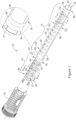
- FIG. 1 illustrates outer sheath 30, ribcage 31 and/or spine member (e.g., support member) 40 fixedly attached to liner 20.
- outer sheath 30, ribcage 31 and/or spine 40 may be disposed (e.g., attached) along a portion of liner 20 from distal portion 26 to proximal portion 24.
- outer sheath 30 may include one or more apertures (e.g., openings) 32 extending through at least a portion of the wall thickness of sheath 30. As shown in FIG. 1 , the one or more apertures 32 may be aligned with one another along the central longitudinal axis 35 of introducer 10. For example, FIG.
- FIG. 1 shows the one or more apertures 32 positioned along the first expandable portion 14, whereby the one or more apertures 32 are aligned with the longitudinal axis 35 of the first expandable portion 14. Additionally, apertures 32 may be positioned between adjacent reinforcement members 38. For example, FIG. 1 shows apertures 32 positioned between two reinforcement members 38. As will be described in greater detail below, the distal portion 26 of introducer 10 may include an atraumatic tip member 28. The above discussion is not intended to be limiting. Rather, it is contemplated that the one or more apertures 32 may be located on any portion of introducer 10.
- collar 39 it can be appreciated that in some instances it may be desirable for collar 39 to be positioned overtop (e.g., overlap, extend around, cover, etc.) a portion of the distal portion 37 of ribcage 31. In other words, in some instances it may be desirable for a portion of collar 39 to be positioned radially outward of the distal portion 37 of ribcage 31.
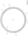
- FIG. 2 illustrates an example ribcage 31.
- ribcage 31 includes a first set of rib members 43 positioned adjacent (e.g., interdigitated, interlaced, etc.) a second set of rib members 33.
- FIG. 2 illustrates that both the first set of rib members 43 and the second set of rib members 33 include a curved portion.
- FIG. 2 further illustrates that the first set of rib members 43 and the second set of rib members 33 extend away from a central spine portion 45. Specifically, the first set of rib members 43 extend away from the central spine portion 45 in a clockwise direction while the second set of rib members 33 extend away from the central spine portion 45 in a counterclockwise direction.
- first set of rib members 43 may be described as extending away from a first lateral edge 47 of central spine member 45 and the second set of rib members 33 may be described as extending away from a second lateral edge 49 of central spine member 45.
- first set of rib members 43 and second set of rib members 33 extend away from the first lateral edge 47 and second lateral edge 49 of spine member 45, they eventually begin to curve back toward and interdigitate with one another.
- the curved shape of both first set of rib members 43 and second set of rib members 33 forms a lumen 51.
- Lumen 51 may include a diameter depicted as "D 1 " in FIG. 2 .
- liner 20 may extend within lumen 51.
- ribcage 31 is able to shift (e.g., radially expand) from a non-expanded configuration (such as that shown in FIG. 2 ) to an expandable configuration shown in FIG. 3 .
- the diameter of lumen 51 shown in FIG. 2 may increase to define a larger diameter (depicted as "D 2 " in FIG. 3 ).
- FIG. 3 illustrates in accordance with the invention that as ribcage 31 expands, the first set of rib members 43 and the second set of rib members 33 radially separate from one another.
- FIG. 3 depicts the radial separation of the first set of rib members 43 from the second set of rib members 33 via a plurality of double-ended arrows.
- the tips of the double-ended arrows shown in FIG. 3 represent the radial separation between the ends of each of the first set of rib members 43 and the second set of rib members 33, respectively.
- FIG. 4 shows an example step in manufacturing introducer 10.
- FIG. 4 shows liner 20 (discussed above with respect to FIG. 1 ) having a substantially annular shape and a lumen 22 extending at least partially therethrough.
- the lumen 22 may extend from a proximal end 24 of liner 20 to a distal end 26 of liner 20. Additionally, the lumen 22 may extend completely through an entire length of liner 20. It is contemplated that other shapes and/or configurations are possible within the scope of the present disclosure, as will be apparent from the discussion below, and other shapes or configurations discussed herein may be used in the configuration(s) schematically shown in the FIGs.
- liner 20 may be described as having a compliant elongated tubular structure having a lumen 22 extending therethrough from proximal end 24 to a distal end 26.
- Liner 20 may include a wall having an inner surface and an outer surface. In some examples, a thickness of the wall may be defined by the inner surface and the outer surface.
- liner 20 and/or lumen 22 may be configured to radially expand from a delivery configuration to an expanded configuration when subjected to a radially outward force from within the lumen 22 and/or liner 20.
- liner 20 may be substantially or completely compliant and/or liner 20 may have no radial self-bias - that is, no radially inward self-bias and/or no radially outward self-bias.
- liner 20 may be non-self-supporting and may not include a mechanism to radially expand and/or open on its own, such as absent a radially outward force exerted upon liner 20.
- liner 20 may require a device or object that has a greater outer diameter than an inner diameter of lumen 22 and/or liner 20 to be disposed within lumen 22 to push and/or force liner 20 radially outward toward the expanded configuration.
- liner 20 may not require a radially inward force be applied upon itself to collapse itself inward when there is no device, object, etc. disposed within lumen 22. In other words, liner 20 may not be held open or maintain a particular expanded size on its own, or liner 20 may be non-self-supporting as mentioned above. Similarly, liner 20 may not be biased to collapse inwardly on its own. In other words, liner 20 may take the shape and/or form of surrounding tissue(s) after being expanded.
- a constriction in or of a vessel or body lumen in which liner 20 is disposed may urge liner 20 radially inward, but liner 20 is not self-biased inwardly on its own, for example, liner 20 may have zero return force after expanding/opening.
- lumen 22 may have a first inner diameter defined by the inner surface of the wall of liner 20.
- the first inner diameter may be defined as a first inner radial extent and/or distance from a central longitudinal axis 35 of liner 20 and/or the expandable introducer 10.
- lumen 22 may have a second inner diameter defined by the inner surface of the wall.
- the second inner diameter may instead be defined as a second inner radial extent and/or distance from a central longitudinal axis 35 of liner 20 and/or the expandable introducer 10.
- the second inner diameter may be greater than the first inner diameter.
- the second inner radial extent may be greater than the first inner radial extent.
- liner 20 may have an outer diameter and/or outer radial extent defined by the outer surface of the wall of liner 20.
- liner 20 may have a first outer diameter and/or first outer radial extent defined by the outer surface of the wall.
- liner 20 may have a second outer diameter and/or a second outer radial extent defined by the outer surface of the wall.
- the second outer diameter may be greater than the first outer diameter.
- the second outer radial extent may be greater than the first outer radial extent.
- liner 20 includes one or more folds 34 formed therein in the delivery configuration.
- the one or more folds 34 may include two folds, three folds, four folds, five folds, six folds, seven folds, eight folds, nine folds, ten folds, or another desirable number or quantity of folds.
- liner 20 may be disposed radially inward of outer sheath 30.
- the one or more folds 34 may each fold back on themselves to form, for example, a wave shape, an S-shape, T-shape and/or a Z-shape when viewed in cross-section.
- liner 20 may be made from an inelastic material, it may be configured to expand radially outward to a predetermined maximum second inner diameter and/or a second inner radial extent, but may not stretch or expand radially outward beyond the predetermined maximum second inner diameter and/or second inner radial extent.
- the inner surface of the wall of liner 20 may include one or more layers or coatings, such as a lubricious coating, a hydrophilic coating, a hydrophobic coating, or other suitable coatings, and the like, or liner 20 may include a lubricant disposed within the lumen 22.
- an outer surface of the expandable introducer 10 and/or outer sheath 30 may include one or more layers or coatings, such as a lubricious coating, a hydrophilic coating, a hydrophobic coating, or other suitable coating, and the like, or the expandable introducer 10 and/or outer sheath 30 may include a lubricant disposed upon the outer surface thereof.
- FIG. 4 shows both ribcage 31 and spine member 40 positioned along the outer surface of liner 20.
- Ribcage 31 may have the first set of rib members 43 and a second set of rib members 33 (discussed above) extending along an outer surface of liner 20.
- spine member 40 may have one or more reinforcement member 38 extending along an outer surface of liner 20.
- both ribcage 31 and/or spine member 40 may be positioned (e.g., attached, fused, glued, tacked, adhered, etc.) to the outer surface of liner 20 during the manufacturing process.
- ribcage 31 and/or spine member 40 may be positioned on the outer surface of liner 20 prior to outer sheath 30 being positioned over the combination of liner 20 and outer sheath 30.
- outer sheath 30 may be formed from a polymeric material, which may form at least a portion of a wall of outer sheath 30. In some examples, outer sheath 30 may be formed from the same material as liner 20. In some examples, outer sheath 30 may be formed from a different material than liner 20. In some examples, some or all of outer sheath 30 may be fixedly attached to the outer surface of the wall of liner 20. In some examples, the entire outer sheath 30 may be fixedly attached to the outer surface of the wall of liner 20, ribcage 31 and/or spine 40. However, as will be discussed in greater detail below, in some examples outer sheath 30 may be free from attachment to all or a portion of liner 20, ribcage 31 and/or spine 40.
- outer sheath 30 may extend continuously around a circumference of liner 20 in a first configuration. In some examples, at least a portion of outer sheath 30 may be discontinuous. As will be discussed in greater detail below, in some examples outer sheath 30 may include a plurality of apertures 32 (e.g., openings, cutouts, perforations, notches, holes, apertures, or other weakening features) formed in the wall of outer sheath 30 which effectively remove at least (or in some cases, only) a portion of the wall of outer sheath 30. While apertures 32 shown in FIG. 5 are substantially hexagonal, it is contemplated that apertures 32 may be any shape. For example, apertures 32 may be circular, square, rectangular, ovular, triangular, diamond shaped, or the like.
- apertures 32 may be circular, square, rectangular, ovular, triangular, diamond shaped, or the like.
- the plurality of apertures 32 formed in the wall of outer sheath 30 may be arranged in one or more longitudinal lines along the length of the expandable introducer 10, liner 20, and/or outer sheath 30. As discussed above, apertures 32 may be positioned in distal portion 55 and thereby aligned with spine member 40 along first expandable portion 14. Further, the plurality of apertures 32, or other weakening features formed in the wall of outer sheath 30 may extend laterally and/or transversely through the wall of outer sheath 30 relative to the central longitudinal axis 35.
- a wall thickness of the outer sheath may be tapered about the circumference of liner 20 such that a reduced thickness region of outer sheath 30 is disposed adjacent to, radially outward of, in communication with, and/or directly over the one or more folds 34 of liner 20.
- the apertures 32 included in outer sheath 30 may be spaced apart from one another.
- FIG. 5 shows adjacent apertures 32 located near the distal end 26 of outer sheath 30 spaced apart from one another a distance "W”.
- FIG. 5 shows two other adjacent apertures 32 located near the proximal end 24 of outer sheath 30 spaced apart from one another a distance "Z”.
- distance "W” and distance "Z” may be equal.
- all the apertures 32 positioned along outer sheath 30 may be spaced equidistant from one another.
- distances "W” and "Z” may be different.
- apertures 32 may include variable spacing between one another. For example, it can be appreciated that the spacing between apertures 32 may gradually increase from the distal portion 26 to the proximal portion 24 of outer sheath 30.
- FIG. 5 illustrates the apertures 32 having a surface area. While the term surface area may be used to herein, the "surface area,” of a given aperture 32 as described herein may be defined as the "area" bounded by the shape of a given aperture 32. For example, in FIG. 5 , the surface area of a given aperture 32 may be defined as the area bounded by an individual hexagon. Further, FIG. 5 shows two different individual apertures 42 and 44. Aperture 42 may be positioned near the distal end 26 of outer sheath 30 while aperture 44 may be positioned near the proximal end 24 of outer sheath 30. In some examples, the surface area of the apertures 32 of outer sheath 30 may be equal. In other examples, such as that shown in FIG.
- the surface area of apertures 32 may be different.
- the surface area of aperture 42 may be larger than that of aperture 44.
- the area of apertures 32 may decrease along outer sheath 30 from the distal portion 26 to the proximal portion 24.
- the size, shape and/or spacing between apertures 32 may change.
- smaller apertures e.g., aperture 44
- various arrangements, spacing, areas, surface areas and/or alignments of apertures 32 may be utilized in the design of outer sheath 30.
- FIG. 6 illustrates liner 20 including three folded sections 34 extending along the inner surface of liner 20. While FIG. 6 shows three folded sections 34, it is contemplated that liner 20 may include more or less than three folded sections 34. For example, liner 20 may include 1, 2, 3, 4, 5, 6, 7, 8, 9, 10 or more folded sections 34. Further, FIG. 6 illustrates that a portion of ribcage 31 may attached (e.g., tacked, fused, integrated, engaged, etc.) with the tubular wall of outer sheath 30 at attachment location 41. In other words, FIG.
- FIG. 6 further illustrates first rib member 43 and second rib member 33 extending away from spine portion 45 in a clockwise direction and counterclockwise direction, respectively.
- both first rib member 43 and second rib member 33 include a curved portion which is positioned along the inner surface of sheath member 30, whereby the curved portion of first rib member 43 extends away from spine portion 45 in a first direction (e.g., clockwise direction) and the second rib member 33 extends away from the spine portion 45 in a second direction (e.g., counterclockwise direction).
- An example methodology to construct the introducer 10 may include configuring ribcage 31, spine member 40, outer sheath 30 and liner 20 as shown in FIG. 6 followed by applying heat such that outer sheath member melts (e.g., reflows) around ribcage 31 and/or liner 20.
- liner 20 may be constructed from a material that has a higher melting point than either outer sheath 30 and/or ribcage 31, and therefore, will not melt upon the application of heat sufficient to melt outer sheath 30 and/or ribcage 31 together.
- FIG. 7 represents the cross-section of introducer 10 after manufacturing.
- FIG. 7 illustrates that spine 40 is incorporated into the tubular wall of outer sheath 30.
- FIG. 7 illustrates that in some examples, outer sheath 30 and spine member 40 may be manufactured (e.g., melted/reflowed together) such that they form a unitary member.
- spine member 40 may include greater or less than three support members 38.
- spine 40 may include 1, 2, 3, 4, 5, 6, 7, 8, 9, 10 or more support members 38.
- outer sheath 30 may include one or more apertures 32 extending at least partially through the wall thickness of outer sheath 30.
- the detailed view in FIG. 7 shows one example of an aperture 32 having extending partially through the tubular wall of outer sheath 30.
- the reduced wall thickness of aperture 32 is depicted as thickness "X.”
- a portion of the tubular wall of outer sheath 30 adjacent to aperture 32 is depicted as "Y.” It can be seen that the thickness "X" of aperture 32 is less than the thickness "Y.”
- the reduced wall thickness "X" (as compared to wall thickness "Y”) may create a preferential "tear point" within outer sheath 30.
- aperture(s) 32 may define a perforated tear line extending along introducer 10.
- the apertures 32 e.g., openings, cutouts, perforations, notches, holes
- the apertures 32 may be positioned adjacent to, radially outward of, in communication with, and/or directly over the one or more folds 34 formed in liner 20.
- FIG. 7 shows apertures 32 positioned directly over the one or more folds 34 in liner 20.
- apertures 32 may be aligned at a point along outer sheath 30 in which fold 34 begins to wrap underneath outer sheath 30. It can be appreciated that the point at which aperture 32 is aligned with fold 34 may be the point at which fold 34 initially begins to separate when liner 20 shifts from the configuration shown in FIG. 7 to an expanded configuration.
- an example methodology to construct the introducer 10 may include configuring spine 40, outer sheath 30 and liner 20 as shown in FIG. 8 (which depicts the introducer 10 in an intermediate state/configuration during the example manufacturing process) followed by applying heat such that outer sheath member 30 melts (e.g., reflows) and encapsulates spine member 40 as shown in FIG. 7 (FIG. 7 depicts the introducer shown in FIG. 8 after the application of heat and melting/reflow process).
- liner 20 may be constructed from a material that has a higher melting point than either outer sheath 30 or spine member 40, and therefore, will not melt upon the application of heat sufficient to melt outer sheath 30 and/or spine member 40 together.
- liner 20 may be constructed from a non-thermoplastic material designed to resist melting while heat is applied to reflow outer sheath 30 and spine 40 together.
- arrangement of liner 20, outer sheath 30 and spine member 40 may include a variety of configurations throughout the manufacturing steps.
- examples contemplated herein may include different positions, alignment, spacing, sizes, dimensions, etc. of spine 40, liner 20 and/or sheath 30 relative to one another during the manufacturing process and/or final design.
- outer sheath 30 may include a given wall thickness at various locations along its length. It can further be appreciated that the wall thickness of outer sheath 30 may vary along its length. For example, while some examples contemplated herein may include apertures 32 being defined as "holes" through the wall of outer sheath 30, in other examples, apertures 32 may be defined as substantially “thinner” sections of the wall of outer sheath 30.
- outer sheath 30 may be configured to separate, split, or tear as liner 20 is expanded from a first configuration to a second, expanded configuration. The expansion may be due to a radially outward force applied from within liner 20.
- outer sheath 30 may be configured to separate, split, perforate and/or tear along and/or through the plurality of apertures 32, or other weakening features formed in the wall of outer sheath 30.
- outer sheath 30 may separate, split, or tear where outer sheath 30 is discontinuous and/or constructed of a thinner material.
- the expansion of sheath 30 may correlate with the expansion of the lumen 22.
- Lumen 22 may expand from a first inner diameter and/or the first inner radial extent to a second inner diameter and/or a second inner radial extent.
- the plurality of apertures 32, or other weakening features formed in the wall of outer sheath 30 may be positioned adjacent to, radially outward of, in communication with, and/or directly over the one or more folds 34 formed in liner 20.
- the plurality of apertures 32, or other weakening features formed in the wall of outer sheath 30 may be arranged in one or more longitudinal lines along the length of the expandable introducer 10, liner 20 and/or outer sheath 30.
- the reduced thickness region and/or a substantially thinner thickness of outer sheath 30 may be disposed adjacent to, radially outward of, in communication with, and/or directly over the one or more folds 34 and/or the two or more secondary folds of liner 20.
- FIG. 9 is a cross-sectional view (along line 6-6 of FIG. 1 ) of the second expandable section 12 of introducer 10 in an expanded configuration.
- FIG. 9 may depict the expanded configuration of the unexpanded introducer illustrated in FIG. 6 .
- FIG. 6 may depict introducer 10 prior to a medical device being inserted through second expandable section 12 of introducer 10
- FIG. 9 may depict introducer 10 after a medical device has been inserted through second expandable section 12.
- liner 20 has expanded to a position in which the three folded sections 34 (shown in FIG. 6 ) have expanded (e.g., unfolded) to a position in which the outer surface of liner 20 contacts the inner surface of first rib member 43 and second rib member 33 of ribcage 31. Additionally, it can be appreciated that liner 20 may continue to expand after it initially contacts the inner surface of ribcage 31, thereby applying a radially outward force on the first rib member 43 and second rib member 33 of ribcage 31.
- first rib member 43 and second rib member 33 of ribcage 31 may expand (e.g., flex) radially outward to accommodate the outward expansion of liner 20.
- FIG. 9 illustrates the increased distance between the ends of first rib member 43 and second rib member 33.
- first rib member 43 and second rib member 33 of ribcage 31 may slide along the outer surface of liner 20.
- sheath 30 may slide along the outer surface of ribcage 31 and/or liner 20. Further, in some instances a portion of sheath member 30 may stretch to accommodate the expanded configuration (e.g., increased diameters) of both liner 20 and/or ribcage 31). It is contemplated that as sheath 30 stretches, its wall thickness may decrease.
- introducer 10 may contract to a configuration that resembles the unexpanded configuration of introducer 10 described above. It can be appreciated that after introducer 10 has been expanded, its configuration may be different from its configuration pre-expansion. For example, after having been expanded, a portion of liner 20 may extend beyond first rib member 43 and second rib member 33 of ribcage 31. In other words, a portion of liner 20 may be positioned between the outer surface of first rib member 43 and/or second rib member 33 and the inner surface of sheath 30.
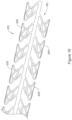
- FIG. 10 is a perspective view of an example spine member 40 including reinforcement members 38 extending from a distal end 26 of spine 40 to a proximal end 24 of spine 40.
- FIG. 6 shows spine member 40 member having openings 46 defined between adjacent reinforcement members 38. While FIG. 6 shows spine member 40 having three reinforcement members 38, it is contemplated that spine member 40 may have less than or greater than three reinforcement members 38. For example, spine member 40 may have 1, 2, 3, 4, 5, 6, 7, 8, 9, 10 or more reinforcement members 38. Further, FIG. 6 shows that in some examples, the width of reinforcement members 38 may be substantially uniform. In other words, the width of reinforcement members 38 may remain substantially uniform along spine member 40 from proximal end 24 to distal end 26. Additionally, FIG. 6 shows reinforcement members 38 spaced substantially equidistant around longitudinal axis 34. However, it is further contemplated that reinforcement members 38 may be spaced at variable distances around longitudinal axis 34.
- FIG. 11 illustrates another example spine member 48.
- the spine member 48 of FIG. 11 may be similar to the spine member 40 shown in FIG. 10 .
- the spine member 48 of FIG. 11 may include one or more reinforcement members 38 having a variable width along the length of spine member 48.
- FIG. 11 shows an example reinforcement member 38 having a width "A" at one location and a different width "B" at a different location.
- width "B" may be substantially less than width "A.”
- width "B” may be substantially greater than width "A.”
- the width of one or more of reinforcement members 38 may taper in any direction along spine member 48. As illustrated in FIG.
- the width of reinforcement members 38 may taper from width "A" to a width "B," whereby width "B" remains substantially constant in at least a portion of the distal region 26 of introducer 10.
- any example spine member described herein may include a given wall thickness at various locations along its length. It can further be appreciated that the wall thickness of any spine member described herein may vary along its length
- FIG. 10 and FIG. 11 show spine members 40 and 48 including collar portions 82.
- Collars 82 may be utilized during the manufacturing process and may or may not be positioned at the distal 26 and/or proximal 24 end of spine members 40 and 48. In some instances, collars 82 may be removed during the manufacturing process.
- manufacturing introducer 10 may result in introducer 10 having one or more radially extending bumps (e.g., raised portions, ridges, etc.).
- the raised portions may extend radially away from the outer surface of introducer 10.
- the one or more raised portions may extend radially away from the outer surface of outer sheath 30.
- a raised portion may substantially align with (e.g., be positioned above) a folded portion 34 of liner 20.
- FIG. 12 illustrates an example section of liner 20 which may be removed prior to performing one or more manufacturing steps.
- FIG. 12 shows a line 70 along which a cut, skive, grinding, shaving, etc. may be performed to remove material prior to performing one or more manufacturing steps. It can appreciated that any suitable method may be utilized to remove a portion of liner 20.
- the material removed from liner 20 may include a portion of one or more folded sections 34.
- FIG. 12 shows line 70 which may represent a cut which removed a portion of folded section 34.
- FIG. 12 shows reinforcement members 38.
- Reinforcement members 38 may have material removed from a distal end thereof.
- one or more reinforcement members 38 may include a tapered, beveled or chamfered distal end.
- FIG. 13 shows a side view of the end of liner 20, which may or may not include outer sheath 30 and/or reinforcement members 38.
- reference number 76 may define a liner 20, outer sheath 30, spine 40 or any combination thereof.
- reference numeral 74 may define a spine member or folded section 34 of liner 20.
- the distal end 26 of example member 76 may include a radius, chamfer and/or bevel around the circumference example member 76.
- This bevel, chamfer and/or radius may represent material which has been removed from the distal end of example member 76 prior to performing additional manufacturing steps.
- the liner/spine 20/40 discussed above may have a bevel, chamfer and/or radius applied to its distal end during the manufacturing process.
- An example method of use of introducer 10 may include inserting introducer 10 into and/or navigated within a vessel or body lumen to a target site or area of interest.
- the vessel or body lumen may include a partial or total occlusion or obstruction formed therein.
- the introducer 10 may be used in a vessel or body lumen that does not include a partial or total occlusion therein.
Landscapes
- Health & Medical Sciences (AREA)
- Life Sciences & Earth Sciences (AREA)
- Surgery (AREA)
- General Health & Medical Sciences (AREA)
- Public Health (AREA)
- Engineering & Computer Science (AREA)
- Biomedical Technology (AREA)
- Heart & Thoracic Surgery (AREA)
- Veterinary Medicine (AREA)
- Animal Behavior & Ethology (AREA)
- Medical Informatics (AREA)
- Pathology (AREA)
- Nuclear Medicine, Radiotherapy & Molecular Imaging (AREA)
- Molecular Biology (AREA)
- Pulmonology (AREA)
- Hematology (AREA)
- Biophysics (AREA)
- Anesthesiology (AREA)
- Media Introduction/Drainage Providing Device (AREA)
- Surgical Instruments (AREA)
Claims (9)
- Dispositif d'introduction (10), comprenant :un revêtement intérieur (20) incluant une lumière (22), une région proximale (24), et au moins une partie pliée (34) s'étendant longitudinalement le long de la région proximale ;un élément de support extensible (31), l'élément de support incluant une colonne vertébrale (40) s'étendant le long de la longueur de l'élément de support (31) et une pluralité de nervures (33, 43) s'étendant le long d'une longueur de l'élément de support (31), la pluralité de nervures incluant un premier ensemble d'éléments de nervure (43) et un second ensemble d'éléments de nervure (33) ; etune gaine (30) fixée à au moins une partie de l'élément de support (31) ; caractérisé en ce quel'élément de support (31) est conçu pour passer d'une première position dans laquelle le premier ensemble d'éléments de nervure (43) est interdigité avec le second ensemble d'éléments de nervure (33) à une position déployée dans laquelle le premier ensemble d'éléments de nervure (43) et le second ensemble d'éléments de nervure (33) se séparent radialement l'un de l'autre, en ce que la colonne vertébrale est fixée à la gaine, et en ce que la pluralité de nervures (33, 43) sont libres de se déplacer par rapport au revêtement (20), à la gaine (30), ou à la fois au revêtement (20) et à la gaine (30).
- Dispositif d'introduction selon la revendication 1, dans lequel l'élément de support extensible (31) s'étend autour d'au moins une partie du revêtement intérieur (20).
- Dispositif d'introduction selon l'une quelconque des revendications 1 à 2, dans lequel l'élément de support (31) est positionné entre le revêtement intérieur (20) et la gaine (30).
- Dispositif d'introduction selon l'une quelconque des revendications 1 à 3, dans lequel l'au moins une partie pliée (34) permet au revêtement intérieur (20) de se déployer radialement.
- Dispositif d'introduction selon l'une quelconque des revendications 1 à 4, dans lequel l'au moins une partie pliée (34) s'étend le long au moins d'une partie d'une surface intérieure de l'élément de support (31).
- Dispositif d'introduction selon l'une quelconque des revendications 1 à 5, dans lequel au moins une partie de la gaine (30) est configurée pour se déployer lorsque l'au moins une partie pliée (34) se déploie radialement.
- Dispositif d'introduction selon la revendication 1, dans lequel le premier ensemble d'éléments de nervure (43) sont fixés à un premier bord latéral (47) de la colonne vertébrale (40), et dans lequel le second ensemble d'éléments de nervure (33) sont fixés à un second bord latéral (49) de la colonne vertébrale (40).
- Dispositif d'introduction selon l'une quelconque des revendications précédentes,dans lequel le premier ensemble d'éléments de nervure (43) est fixé à la colonne vertébrale (40), dans lequel chacun du premier ensemble d'éléments de nervure (43) s'étend vers l'extérieur à partir de la colonne vertébrale (40) dans une première direction ; etdans lequel le second ensemble d'éléments de nervure (33) est fixé à la colonne vertébrale (40), dans lequel chacun du second ensemble d'éléments de nervure (33) s'étend vers l'extérieur à partir de la colonne vertébrale (40) dans une seconde direction différente de la première direction.
- Dispositif d'introduction selon l'une quelconque des revendications précédentes, dans lequel les premier et second ensembles d'éléments de nervure s'enroulent autour d'au moins une partie du revêtement intérieur (20).
Applications Claiming Priority (2)
| Application Number | Priority Date | Filing Date | Title |
|---|---|---|---|
| US201662431972P | 2016-12-09 | 2016-12-09 | |
| PCT/US2017/065534 WO2018107147A1 (fr) | 2016-12-09 | 2017-12-11 | Dispositif d'introduction ayant des capacités d'extension |
Publications (2)
| Publication Number | Publication Date |
|---|---|
| EP3551103A1 EP3551103A1 (fr) | 2019-10-16 |
| EP3551103B1 true EP3551103B1 (fr) | 2025-03-12 |
Family
ID=61007773
Family Applications (1)
| Application Number | Title | Priority Date | Filing Date |
|---|---|---|---|
| EP17832615.3A Active EP3551103B1 (fr) | 2016-12-09 | 2017-12-11 | Dispositif d'introduction ayant des capacités d'extension |
Country Status (5)
| Country | Link |
|---|---|
| US (1) | US10980569B2 (fr) |
| EP (1) | EP3551103B1 (fr) |
| JP (1) | JP6861281B2 (fr) |
| CN (1) | CN110300557B (fr) |
| WO (1) | WO2018107147A1 (fr) |
Families Citing this family (24)
| Publication number | Priority date | Publication date | Assignee | Title |
|---|---|---|---|---|
| US8790387B2 (en) | 2008-10-10 | 2014-07-29 | Edwards Lifesciences Corporation | Expandable sheath for introducing an endovascular delivery device into a body |
| US12194256B2 (en) | 2015-04-10 | 2025-01-14 | Edwards Lifesciences Corporation | Expandable sheath |
| US10327896B2 (en) | 2015-04-10 | 2019-06-25 | Edwards Lifesciences Corporation | Expandable sheath with elastomeric cross sectional portions |
| US10792471B2 (en) | 2015-04-10 | 2020-10-06 | Edwards Lifesciences Corporation | Expandable sheath |
| US10548631B2 (en) | 2016-03-04 | 2020-02-04 | Boston Scientific Scimed Inc. | Introducer with expandable capabilities |
| US10912919B2 (en) | 2017-01-23 | 2021-02-09 | Edwards Lifesciences Corporation | Expandable sheath |
| US10799685B2 (en) | 2017-03-09 | 2020-10-13 | Edwards Lifesciences Corporation | Expandable sheath with longitudinally extending reinforcing members |
| CN110753566A (zh) * | 2017-06-13 | 2020-02-04 | 波士顿科学国际有限公司 | 具有可扩张能力的导引器 |
| EP3752236B1 (fr) | 2018-02-15 | 2023-12-27 | Boston Scientific Scimed, Inc. | Dispositif d'introduction avec capacités de déploiement |
| WO2019199692A1 (fr) | 2018-04-09 | 2019-10-17 | Edwards Lifesciences Corporation | Gaine expansible |
| US11786695B2 (en) | 2018-07-25 | 2023-10-17 | Edwards Lifesciences Corporation | Methods of making an expandable sheath |
| EP3849646B1 (fr) * | 2018-09-10 | 2022-10-26 | Boston Scientific Scimed, Inc. | Introducteur avec capacités de déploiement |
| EP4275629A3 (fr) * | 2018-09-20 | 2023-12-27 | Three Peaks Medical Pty Ltd | Dispositif de gaine ajustable |
| WO2020123486A1 (fr) | 2018-12-10 | 2020-06-18 | Boston Scientific Scimed, Inc. | Système d'administration de dispositif médical comprenant un élément de résistance |
| CN111134755B (zh) * | 2019-12-17 | 2021-07-20 | 先健科技(深圳)有限公司 | 支撑件和医疗器械 |
| US12589218B2 (en) | 2020-08-03 | 2026-03-31 | C. R. Bard, Inc. | Intermittent-catheter assembly and methods thereof |
| CN113209446A (zh) * | 2021-03-25 | 2021-08-06 | 上海苏畅医疗科技有限公司 | 一种导引导管及导引导管系统 |
| USD1117752S1 (en) | 2023-01-19 | 2026-03-10 | Mirus Llc | Expandable medical sheath |
| USD1118925S1 (en) | 2023-01-23 | 2026-03-17 | Mirus Llc | Expandable medical sheath |
| CN113456990B (zh) * | 2021-07-30 | 2025-04-04 | 北京迈迪斯医疗技术有限公司 | 介入导管器械 |
| EP4395862A1 (fr) * | 2021-09-02 | 2024-07-10 | Edwards Lifesciences Corporation | Gaine expansible pour pose d'implant |
| WO2023144693A1 (fr) * | 2022-01-28 | 2023-08-03 | Medtronic, Inc. | Gaine d'introduction extensible |
| EP4598618A1 (fr) * | 2022-10-05 | 2025-08-13 | The Cleveland Clinic Foundation | Appareil et procédé d'utilisation d'un introducteur perforé |
| US11969188B1 (en) | 2023-09-18 | 2024-04-30 | Laplace Interventional Inc. | Dilating introducer devices and methods for vascular access |
Citations (8)
| Publication number | Priority date | Publication date | Assignee | Title |
|---|---|---|---|---|
| US20040143286A1 (en) * | 2003-01-17 | 2004-07-22 | Johnson Eric G. | Catheter with disruptable guidewire channel |
| WO2009108816A1 (fr) * | 2008-02-26 | 2009-09-03 | Boston Scientific Scimed, Inc. | Cathéter à ballonnet avec partie d’extrémité durable |
| US20100082000A1 (en) * | 2008-09-30 | 2010-04-01 | Medtronic, Inc. | Catheter system with reinforced member |
| WO2017123802A1 (fr) * | 2016-01-13 | 2017-07-20 | Medtronic Inc. | Dispositif de placement pour une valvule cardiaque endoprothétique |
| WO2017151659A1 (fr) * | 2016-03-04 | 2017-09-08 | Boston Scientific Scimed, Inc. | Dispositif d'introduction à capacités extensibles |
| WO2017172451A1 (fr) * | 2016-03-31 | 2017-10-05 | Medtronic Vascular Inc. | Gaine d'introducteur extensible munie d'un mécanisme de direction |
| WO2018009416A1 (fr) * | 2016-07-08 | 2018-01-11 | Edwards Lifesciences Corporation | Gaine extensible et les procédés d'utilisation de celle-ci. |
| WO2019027956A1 (fr) * | 2017-07-31 | 2019-02-07 | Boston Scientific Scimed, Inc. | Système d'introduction avec capacités d'extension |
Family Cites Families (15)
| Publication number | Priority date | Publication date | Assignee | Title |
|---|---|---|---|---|
| US5256150A (en) * | 1991-12-13 | 1993-10-26 | Endovascular Technologies, Inc. | Large-diameter expandable sheath and method |
| CN101336094A (zh) * | 2005-12-08 | 2008-12-31 | 新特斯有限责任公司 | 用于治疗骨头的装置和方法 |
| US8377036B2 (en) | 2007-09-14 | 2013-02-19 | Avalon Laboratories, Inc. | Cannula reinforcing band and method |
| US20120095432A1 (en) * | 2010-10-15 | 2012-04-19 | Nath Iyunni Venkata Sesha Sayi | Catheter and method of insertion |
| US8690936B2 (en) * | 2008-10-10 | 2014-04-08 | Edwards Lifesciences Corporation | Expandable sheath for introducing an endovascular delivery device into a body |
| US10046141B2 (en) * | 2008-12-30 | 2018-08-14 | Biosense Webster, Inc. | Deflectable sheath introducer |
| US8518106B2 (en) | 2010-02-17 | 2013-08-27 | Medtronic, Inc. | Catheter assembly with valve crimping accessories |
| JP2012040145A (ja) * | 2010-08-18 | 2012-03-01 | Terumo Corp | 医療用チューブ保護カバー |
| US9907931B2 (en) * | 2012-10-26 | 2018-03-06 | Medtronic, Inc. | Elastic introducer sheath |
| US9192751B2 (en) | 2012-10-26 | 2015-11-24 | Medtronic, Inc. | Elastic introducer sheath |
| US9788943B2 (en) | 2013-06-11 | 2017-10-17 | Medtronic, Inc. | Delivery system with inline sheath |
| US9801657B2 (en) * | 2014-09-12 | 2017-10-31 | Freudenberg Medical, Llc | Expandable introducer sheath |
| US10792471B2 (en) | 2015-04-10 | 2020-10-06 | Edwards Lifesciences Corporation | Expandable sheath |
| US10327896B2 (en) | 2015-04-10 | 2019-06-25 | Edwards Lifesciences Corporation | Expandable sheath with elastomeric cross sectional portions |
| EP3405126A1 (fr) | 2016-01-21 | 2018-11-28 | Boston Scientific Scimed, Inc. | Dispositifs médicaux et procédés d'utilisation associés |
-
2017
- 2017-12-11 EP EP17832615.3A patent/EP3551103B1/fr active Active
- 2017-12-11 US US15/837,174 patent/US10980569B2/en active Active
- 2017-12-11 JP JP2019530712A patent/JP6861281B2/ja active Active
- 2017-12-11 CN CN201780086057.XA patent/CN110300557B/zh active Active
- 2017-12-11 WO PCT/US2017/065534 patent/WO2018107147A1/fr not_active Ceased
Patent Citations (8)
| Publication number | Priority date | Publication date | Assignee | Title |
|---|---|---|---|---|
| US20040143286A1 (en) * | 2003-01-17 | 2004-07-22 | Johnson Eric G. | Catheter with disruptable guidewire channel |
| WO2009108816A1 (fr) * | 2008-02-26 | 2009-09-03 | Boston Scientific Scimed, Inc. | Cathéter à ballonnet avec partie d’extrémité durable |
| US20100082000A1 (en) * | 2008-09-30 | 2010-04-01 | Medtronic, Inc. | Catheter system with reinforced member |
| WO2017123802A1 (fr) * | 2016-01-13 | 2017-07-20 | Medtronic Inc. | Dispositif de placement pour une valvule cardiaque endoprothétique |
| WO2017151659A1 (fr) * | 2016-03-04 | 2017-09-08 | Boston Scientific Scimed, Inc. | Dispositif d'introduction à capacités extensibles |
| WO2017172451A1 (fr) * | 2016-03-31 | 2017-10-05 | Medtronic Vascular Inc. | Gaine d'introducteur extensible munie d'un mécanisme de direction |
| WO2018009416A1 (fr) * | 2016-07-08 | 2018-01-11 | Edwards Lifesciences Corporation | Gaine extensible et les procédés d'utilisation de celle-ci. |
| WO2019027956A1 (fr) * | 2017-07-31 | 2019-02-07 | Boston Scientific Scimed, Inc. | Système d'introduction avec capacités d'extension |
Also Published As
| Publication number | Publication date |
|---|---|
| WO2018107147A1 (fr) | 2018-06-14 |
| CN110300557B (zh) | 2022-06-28 |
| JP2020500636A (ja) | 2020-01-16 |
| JP6861281B2 (ja) | 2021-04-21 |
| EP3551103A1 (fr) | 2019-10-16 |
| US10980569B2 (en) | 2021-04-20 |
| CN110300557A (zh) | 2019-10-01 |
| US20180161064A1 (en) | 2018-06-14 |
Similar Documents
| Publication | Publication Date | Title |
|---|---|---|
| US11931068B2 (en) | Introducer with expandable capabilities | |
| EP3551103B1 (fr) | Dispositif d'introduction ayant des capacités d'extension | |
| US12303651B2 (en) | Fully compliant large bore expandable sheath | |
| US10751178B2 (en) | Introducer with expandable capabilities | |
| EP4085853B1 (fr) | Système d'introduction avec capacités d'extension | |
| US20190083082A1 (en) | Introducer with expandable capabilities | |
| EP3661585B1 (fr) | Dilatateur avec région de mise en prise | |
| US20180325548A1 (en) | Introducer with expandable capabilities |
Legal Events
| Date | Code | Title | Description |
|---|---|---|---|
| STAA | Information on the status of an ep patent application or granted ep patent |
Free format text: STATUS: UNKNOWN |
|
| STAA | Information on the status of an ep patent application or granted ep patent |
Free format text: STATUS: THE INTERNATIONAL PUBLICATION HAS BEEN MADE |
|
| PUAI | Public reference made under article 153(3) epc to a published international application that has entered the european phase |
Free format text: ORIGINAL CODE: 0009012 |
|
| STAA | Information on the status of an ep patent application or granted ep patent |
Free format text: STATUS: REQUEST FOR EXAMINATION WAS MADE |
|
| 17P | Request for examination filed |
Effective date: 20190704 |
|
| AK | Designated contracting states |
Kind code of ref document: A1 Designated state(s): AL AT BE BG CH CY CZ DE DK EE ES FI FR GB GR HR HU IE IS IT LI LT LU LV MC MK MT NL NO PL PT RO RS SE SI SK SM TR |
|
| AX | Request for extension of the european patent |
Extension state: BA ME |
|
| DAV | Request for validation of the european patent (deleted) | ||
| DAX | Request for extension of the european patent (deleted) | ||
| STAA | Information on the status of an ep patent application or granted ep patent |
Free format text: STATUS: EXAMINATION IS IN PROGRESS |
|
| 17Q | First examination report despatched |
Effective date: 20220519 |
|
| GRAP | Despatch of communication of intention to grant a patent |
Free format text: ORIGINAL CODE: EPIDOSNIGR1 |
|
| STAA | Information on the status of an ep patent application or granted ep patent |
Free format text: STATUS: GRANT OF PATENT IS INTENDED |
|
| INTG | Intention to grant announced |
Effective date: 20240517 |
|
| RAP3 | Party data changed (applicant data changed or rights of an application transferred) |
Owner name: BOSTON SCIENTIFIC SCIMED, INC. |
|
| GRAC | Information related to communication of intention to grant a patent modified |
Free format text: ORIGINAL CODE: EPIDOSCIGR1 |
|
| INTG | Intention to grant announced |
Effective date: 20241007 |
|
| GRAS | Grant fee paid |
Free format text: ORIGINAL CODE: EPIDOSNIGR3 |
|
| GRAA | (expected) grant |
Free format text: ORIGINAL CODE: 0009210 |
|
| STAA | Information on the status of an ep patent application or granted ep patent |
Free format text: STATUS: THE PATENT HAS BEEN GRANTED |
|
| AK | Designated contracting states |
Kind code of ref document: B1 Designated state(s): AL AT BE BG CH CY CZ DE DK EE ES FI FR GB GR HR HU IE IS IT LI LT LU LV MC MK MT NL NO PL PT RO RS SE SI SK SM TR |
|
| REG | Reference to a national code |
Ref country code: GB Ref legal event code: FG4D |
|
| REG | Reference to a national code |
Ref country code: CH Ref legal event code: EP |
|
| REG | Reference to a national code |
Ref country code: DE Ref legal event code: R096 Ref document number: 602017088324 Country of ref document: DE |
|
| REG | Reference to a national code |
Ref country code: IE Ref legal event code: FG4D |
|
| REG | Reference to a national code |
Ref country code: NL Ref legal event code: FP |
|
| PG25 | Lapsed in a contracting state [announced via postgrant information from national office to epo] |
Ref country code: RS Free format text: LAPSE BECAUSE OF FAILURE TO SUBMIT A TRANSLATION OF THE DESCRIPTION OR TO PAY THE FEE WITHIN THE PRESCRIBED TIME-LIMIT Effective date: 20250612 |
|
| PG25 | Lapsed in a contracting state [announced via postgrant information from national office to epo] |
Ref country code: FI Free format text: LAPSE BECAUSE OF FAILURE TO SUBMIT A TRANSLATION OF THE DESCRIPTION OR TO PAY THE FEE WITHIN THE PRESCRIBED TIME-LIMIT Effective date: 20250312 |
|
| PG25 | Lapsed in a contracting state [announced via postgrant information from national office to epo] |
Ref country code: ES Free format text: LAPSE BECAUSE OF FAILURE TO SUBMIT A TRANSLATION OF THE DESCRIPTION OR TO PAY THE FEE WITHIN THE PRESCRIBED TIME-LIMIT Effective date: 20250312 |
|
| REG | Reference to a national code |
Ref country code: LT Ref legal event code: MG9D |
|
| PG25 | Lapsed in a contracting state [announced via postgrant information from national office to epo] |
Ref country code: NO Free format text: LAPSE BECAUSE OF FAILURE TO SUBMIT A TRANSLATION OF THE DESCRIPTION OR TO PAY THE FEE WITHIN THE PRESCRIBED TIME-LIMIT Effective date: 20250612 |
|
| PG25 | Lapsed in a contracting state [announced via postgrant information from national office to epo] |
Ref country code: HR Free format text: LAPSE BECAUSE OF FAILURE TO SUBMIT A TRANSLATION OF THE DESCRIPTION OR TO PAY THE FEE WITHIN THE PRESCRIBED TIME-LIMIT Effective date: 20250312 |
|
| PG25 | Lapsed in a contracting state [announced via postgrant information from national office to epo] |
Ref country code: LV Free format text: LAPSE BECAUSE OF FAILURE TO SUBMIT A TRANSLATION OF THE DESCRIPTION OR TO PAY THE FEE WITHIN THE PRESCRIBED TIME-LIMIT Effective date: 20250312 |
|
| PG25 | Lapsed in a contracting state [announced via postgrant information from national office to epo] |
Ref country code: GR Free format text: LAPSE BECAUSE OF FAILURE TO SUBMIT A TRANSLATION OF THE DESCRIPTION OR TO PAY THE FEE WITHIN THE PRESCRIBED TIME-LIMIT Effective date: 20250613 Ref country code: BG Free format text: LAPSE BECAUSE OF FAILURE TO SUBMIT A TRANSLATION OF THE DESCRIPTION OR TO PAY THE FEE WITHIN THE PRESCRIBED TIME-LIMIT Effective date: 20250312 |
|
| REG | Reference to a national code |
Ref country code: AT Ref legal event code: MK05 Ref document number: 1774361 Country of ref document: AT Kind code of ref document: T Effective date: 20250312 |
|
| PG25 | Lapsed in a contracting state [announced via postgrant information from national office to epo] |
Ref country code: SE Free format text: LAPSE BECAUSE OF FAILURE TO SUBMIT A TRANSLATION OF THE DESCRIPTION OR TO PAY THE FEE WITHIN THE PRESCRIBED TIME-LIMIT Effective date: 20250312 |
|
| PG25 | Lapsed in a contracting state [announced via postgrant information from national office to epo] |
Ref country code: SM Free format text: LAPSE BECAUSE OF FAILURE TO SUBMIT A TRANSLATION OF THE DESCRIPTION OR TO PAY THE FEE WITHIN THE PRESCRIBED TIME-LIMIT Effective date: 20250312 |
|
| PG25 | Lapsed in a contracting state [announced via postgrant information from national office to epo] |
Ref country code: PT Free format text: LAPSE BECAUSE OF FAILURE TO SUBMIT A TRANSLATION OF THE DESCRIPTION OR TO PAY THE FEE WITHIN THE PRESCRIBED TIME-LIMIT Effective date: 20250714 |
|
| PG25 | Lapsed in a contracting state [announced via postgrant information from national office to epo] |
Ref country code: IT Free format text: LAPSE BECAUSE OF FAILURE TO SUBMIT A TRANSLATION OF THE DESCRIPTION OR TO PAY THE FEE WITHIN THE PRESCRIBED TIME-LIMIT Effective date: 20250312 Ref country code: PL Free format text: LAPSE BECAUSE OF FAILURE TO SUBMIT A TRANSLATION OF THE DESCRIPTION OR TO PAY THE FEE WITHIN THE PRESCRIBED TIME-LIMIT Effective date: 20250312 |
|
| PG25 | Lapsed in a contracting state [announced via postgrant information from national office to epo] |
Ref country code: AT Free format text: LAPSE BECAUSE OF FAILURE TO SUBMIT A TRANSLATION OF THE DESCRIPTION OR TO PAY THE FEE WITHIN THE PRESCRIBED TIME-LIMIT Effective date: 20250312 |
|
| PG25 | Lapsed in a contracting state [announced via postgrant information from national office to epo] |
Ref country code: EE Free format text: LAPSE BECAUSE OF FAILURE TO SUBMIT A TRANSLATION OF THE DESCRIPTION OR TO PAY THE FEE WITHIN THE PRESCRIBED TIME-LIMIT Effective date: 20250312 Ref country code: CZ Free format text: LAPSE BECAUSE OF FAILURE TO SUBMIT A TRANSLATION OF THE DESCRIPTION OR TO PAY THE FEE WITHIN THE PRESCRIBED TIME-LIMIT Effective date: 20250312 |
|
| PG25 | Lapsed in a contracting state [announced via postgrant information from national office to epo] |
Ref country code: RO Free format text: LAPSE BECAUSE OF FAILURE TO SUBMIT A TRANSLATION OF THE DESCRIPTION OR TO PAY THE FEE WITHIN THE PRESCRIBED TIME-LIMIT Effective date: 20250312 |
|
| PG25 | Lapsed in a contracting state [announced via postgrant information from national office to epo] |
Ref country code: SK Free format text: LAPSE BECAUSE OF FAILURE TO SUBMIT A TRANSLATION OF THE DESCRIPTION OR TO PAY THE FEE WITHIN THE PRESCRIBED TIME-LIMIT Effective date: 20250312 |
|
| PG25 | Lapsed in a contracting state [announced via postgrant information from national office to epo] |
Ref country code: IS Free format text: LAPSE BECAUSE OF FAILURE TO SUBMIT A TRANSLATION OF THE DESCRIPTION OR TO PAY THE FEE WITHIN THE PRESCRIBED TIME-LIMIT Effective date: 20250712 |
|
| PGFP | Annual fee paid to national office [announced via postgrant information from national office to epo] |
Ref country code: NL Payment date: 20251119 Year of fee payment: 9 |
|
| REG | Reference to a national code |
Ref country code: DE Ref legal event code: R097 Ref document number: 602017088324 Country of ref document: DE |
|
| PGFP | Annual fee paid to national office [announced via postgrant information from national office to epo] |
Ref country code: DE Payment date: 20251126 Year of fee payment: 9 |
|
| PG25 | Lapsed in a contracting state [announced via postgrant information from national office to epo] |
Ref country code: DK Free format text: LAPSE BECAUSE OF FAILURE TO SUBMIT A TRANSLATION OF THE DESCRIPTION OR TO PAY THE FEE WITHIN THE PRESCRIBED TIME-LIMIT Effective date: 20250312 |
|
| PLBE | No opposition filed within time limit |
Free format text: ORIGINAL CODE: 0009261 |
|
| STAA | Information on the status of an ep patent application or granted ep patent |
Free format text: STATUS: NO OPPOSITION FILED WITHIN TIME LIMIT |
|
| PGFP | Annual fee paid to national office [announced via postgrant information from national office to epo] |
Ref country code: IE Payment date: 20251121 Year of fee payment: 9 |
|
| REG | Reference to a national code |
Ref country code: CH Ref legal event code: L10 Free format text: ST27 STATUS EVENT CODE: U-0-0-L10-L00 (AS PROVIDED BY THE NATIONAL OFFICE) Effective date: 20260121 |
|
| 26N | No opposition filed |
Effective date: 20251215 |