EP3551331B1 - Dispositif de régulation de température - Google Patents
Dispositif de régulation de température Download PDFInfo
- Publication number
- EP3551331B1 EP3551331B1 EP17795022.7A EP17795022A EP3551331B1 EP 3551331 B1 EP3551331 B1 EP 3551331B1 EP 17795022 A EP17795022 A EP 17795022A EP 3551331 B1 EP3551331 B1 EP 3551331B1
- Authority
- EP
- European Patent Office
- Prior art keywords
- thermal
- site
- active
- sites
- substrate
- Prior art date
- Legal status (The legal status is an assumption and is not a legal conclusion. Google has not performed a legal analysis and makes no representation as to the accuracy of the status listed.)
- Active
Links
Images





Classifications
-
- G—PHYSICS
- G05—CONTROLLING; REGULATING
- G05D—SYSTEMS FOR CONTROLLING OR REGULATING NON-ELECTRIC VARIABLES
- G05D23/00—Control of temperature
- G05D23/19—Control of temperature characterised by the use of electric means
- G05D23/1927—Control of temperature characterised by the use of electric means using a plurality of sensors
- G05D23/193—Control of temperature characterised by the use of electric means using a plurality of sensors sensing the temperaure in different places in thermal relationship with one or more spaces
- G05D23/1932—Control of temperature characterised by the use of electric means using a plurality of sensors sensing the temperaure in different places in thermal relationship with one or more spaces to control the temperature of a plurality of spaces
-
- B—PERFORMING OPERATIONS; TRANSPORTING
- B01—PHYSICAL OR CHEMICAL PROCESSES OR APPARATUS IN GENERAL
- B01L—CHEMICAL OR PHYSICAL LABORATORY APPARATUS FOR GENERAL USE
- B01L7/00—Heating or cooling apparatus; Heat insulating devices
- B01L7/52—Heating or cooling apparatus; Heat insulating devices with provision for submitting samples to a predetermined sequence of different temperatures, e.g. for treating nucleic acid samples
-
- G—PHYSICS
- G05—CONTROLLING; REGULATING
- G05D—SYSTEMS FOR CONTROLLING OR REGULATING NON-ELECTRIC VARIABLES
- G05D23/00—Control of temperature
-
- G—PHYSICS
- G05—CONTROLLING; REGULATING
- G05D—SYSTEMS FOR CONTROLLING OR REGULATING NON-ELECTRIC VARIABLES
- G05D23/00—Control of temperature
- G05D23/19—Control of temperature characterised by the use of electric means
- G05D23/1927—Control of temperature characterised by the use of electric means using a plurality of sensors
- G05D23/193—Control of temperature characterised by the use of electric means using a plurality of sensors sensing the temperaure in different places in thermal relationship with one or more spaces
-
- G—PHYSICS
- G05—CONTROLLING; REGULATING
- G05D—SYSTEMS FOR CONTROLLING OR REGULATING NON-ELECTRIC VARIABLES
- G05D23/00—Control of temperature
- G05D23/19—Control of temperature characterised by the use of electric means
- G05D23/20—Control of temperature characterised by the use of electric means with sensing elements having variation of electric or magnetic properties with change of temperature
- G05D23/2033—Control of temperature characterised by the use of electric means with sensing elements having variation of electric or magnetic properties with change of temperature details of the sensing element
-
- H—ELECTRICITY
- H10—SEMICONDUCTOR DEVICES; ELECTRIC SOLID-STATE DEVICES NOT OTHERWISE PROVIDED FOR
- H10N—ELECTRIC SOLID-STATE DEVICES NOT OTHERWISE PROVIDED FOR
- H10N10/00—Thermoelectric devices comprising a junction of dissimilar materials, i.e. devices exhibiting Seebeck or Peltier effects
- H10N10/10—Thermoelectric devices comprising a junction of dissimilar materials, i.e. devices exhibiting Seebeck or Peltier effects operating with only the Peltier or Seebeck effects
- H10N10/13—Thermoelectric devices comprising a junction of dissimilar materials, i.e. devices exhibiting Seebeck or Peltier effects operating with only the Peltier or Seebeck effects characterised by the heat-exchanging means at the junction
-
- H—ELECTRICITY
- H10—SEMICONDUCTOR DEVICES; ELECTRIC SOLID-STATE DEVICES NOT OTHERWISE PROVIDED FOR
- H10W—GENERIC PACKAGES, INTERCONNECTIONS, CONNECTORS OR OTHER CONSTRUCTIONAL DETAILS OF DEVICES COVERED BY CLASS H10
- H10W40/00—Arrangements for thermal protection or thermal control
- H10W40/20—Arrangements for cooling
- H10W40/28—Arrangements for cooling comprising Peltier coolers
-
- B—PERFORMING OPERATIONS; TRANSPORTING
- B01—PHYSICAL OR CHEMICAL PROCESSES OR APPARATUS IN GENERAL
- B01L—CHEMICAL OR PHYSICAL LABORATORY APPARATUS FOR GENERAL USE
- B01L2200/00—Solutions for specific problems relating to chemical or physical laboratory apparatus
- B01L2200/12—Specific details about manufacturing devices
-
- B—PERFORMING OPERATIONS; TRANSPORTING
- B01—PHYSICAL OR CHEMICAL PROCESSES OR APPARATUS IN GENERAL
- B01L—CHEMICAL OR PHYSICAL LABORATORY APPARATUS FOR GENERAL USE
- B01L2200/00—Solutions for specific problems relating to chemical or physical laboratory apparatus
- B01L2200/14—Process control and prevention of errors
- B01L2200/143—Quality control, feedback systems
- B01L2200/147—Employing temperature sensors
-
- B—PERFORMING OPERATIONS; TRANSPORTING
- B01—PHYSICAL OR CHEMICAL PROCESSES OR APPARATUS IN GENERAL
- B01L—CHEMICAL OR PHYSICAL LABORATORY APPARATUS FOR GENERAL USE
- B01L2300/00—Additional constructional details
- B01L2300/08—Geometry, shape and general structure
- B01L2300/0861—Configuration of multiple channels and/or chambers in a single devices
-
- B—PERFORMING OPERATIONS; TRANSPORTING
- B01—PHYSICAL OR CHEMICAL PROCESSES OR APPARATUS IN GENERAL
- B01L—CHEMICAL OR PHYSICAL LABORATORY APPARATUS FOR GENERAL USE
- B01L2300/00—Additional constructional details
- B01L2300/18—Means for temperature control
- B01L2300/1805—Conductive heating, heat from thermostatted solids is conducted to receptacles, e.g. heating plates, blocks
- B01L2300/1827—Conductive heating, heat from thermostatted solids is conducted to receptacles, e.g. heating plates, blocks using resistive heater
-
- B—PERFORMING OPERATIONS; TRANSPORTING
- B01—PHYSICAL OR CHEMICAL PROCESSES OR APPARATUS IN GENERAL
- B01L—CHEMICAL OR PHYSICAL LABORATORY APPARATUS FOR GENERAL USE
- B01L2300/00—Additional constructional details
- B01L2300/18—Means for temperature control
- B01L2300/1838—Means for temperature control using fluid heat transfer medium
- B01L2300/185—Means for temperature control using fluid heat transfer medium using a liquid as fluid
-
- B—PERFORMING OPERATIONS; TRANSPORTING
- B01—PHYSICAL OR CHEMICAL PROCESSES OR APPARATUS IN GENERAL
- B01L—CHEMICAL OR PHYSICAL LABORATORY APPARATUS FOR GENERAL USE
- B01L2300/00—Additional constructional details
- B01L2300/18—Means for temperature control
- B01L2300/1883—Means for temperature control using thermal insulation
Definitions
- the present technique relates to the field of temperature control, more particularly, it relates to controlling temperatures at multiple sites of a medium.
- Controlling the pattern of heat applied at different sites in a medium can be useful for some applications, such as for control of chemical reactions at the respective sites for example, as chemical reactions can be exponentially dependent on temperature.
- a medium e.g. a fluid or solid
- chemical reactions can be exponentially dependent on temperature.
- EP 0545736 describes independent control of multiple samples which are in close proximity. All the samples in a sample container designed for rapid heat transfer and can be independently regulated to a set point using a temperature feedback control with the temperature monitored by a temperature sensitive element. This is implemented by heating each sample independently and at the same time a cooling means produces a substantial and continuous heat flow from the sample in order to permit an adequate rate of cooling when required. The rate of heat flow through the cooling means is partly determined by a thermal resistance which is including to control the pattern and maximum rate of heat flow to designed levels. By keeping the thermal mass of the temperature controlled components to a minimum it is also possible to change the temperature of the samples very rapidly.
- EP 1974816 describes an integrated microfluidic device having a plurality of chambers on a substrate for handling fluids, a chamber circuit integrated on the substrate for switching signals related to that chamber, and an integrated circuit chip bonded to the substrate, the integrated circuit chip having signal processing circuitry (controller) coupled to the chamber circuit.
- Lower performance switching functions can be carried out on chamber circuitry implemented in low temperature poly silicon, and higher performance signal processing functions can be carried out on the integrated circuit implemented in crystalline silicon.
- the substrate can be glass.
- a controller on the integrated circuit chip can control or read from many chamber circuits in a multiplexed manner, using active matrix techniques.
- the chambers can be used for PCR and the chamber circuits used for temperature sensing and heating.
- Dreinhoefer L H "Controller tuning for a slow nonlinear process", IEEE Control Systems Magazine, IEEE Service Center, Piscataway, NJ, US, vol. 8, no. 2, 30 April 1988, pages 56-50 describes the results obtained by using the Ziegler-Nichols open-loop method of determining the tuning constants for a classical PID temperature controller for a heat-treat furnace. The process being controlled is described, and open-loop test data are presented.
- the invention provides a temperature control device according to claim 1.
- the invention provides a method for controlling temperatures at a plurality of sites of a medium, according to claim 9.
- a temperature control device for controlling temperatures at multiple sites of a medium comprises a number of active thermal sites disposed at respective locations on a substrate, with each active thermal site comprising a heating element for applying a variable amount of heat to a corresponding site of the medium, and a thermal insulation layer disposed between the heating element and the substrate.
- One or more passive thermal regions are disposed between the active thermal sites on the substrate, with each passive thermal region comprising a thermal conduction layer for conducting heat from a corresponding portion of the medium to the substrate.
- the thermal conduction layer of the passive cooling region(s) has a lower thermal resistance in a direction perpendicular to a plane of the substrate than the insulating layer of the active thermal sites.
- the substrate When in use, the substrate can act as a heat sink (either by having the substrate exposed to room temperature, or by providing cooling of the substrate if lower temperatures are required).
- the thermal conduction layer in the passive regions enables the passive regions to provide cooling of the medium in the regions between the active thermal sites, so that less cooling needs to be provided by the active thermal sites themselves.
- This enables the active thermal sites to be designed to be more efficient for heating, since a thermal insulation layer which has a higher thermal resistance can be used between the heating element and the substrate as it is no longer required to allow so much heat to pass to the substrate to support cooling. This means that during heating less heat is lost to the substrate and therefore the overall temperature range supported by the device can be higher.
- the temperature at the corresponding site on the medium is relatively high, then the temperature difference across the heating site would be much larger and so the amount of heat lost to the substrate would be large. Therefore, to heat the corresponding site of the medium to even higher temperature, this would require a great amount of power to be applied to the heating element to counteract the heat lost to the substrate below.
- the maximum power supported by the heating element may be limited due to design constraints. Hence, an approach which uses the same site to provide the full heating/cooling functionality will be limited in the range of temperatures which can be controlled at a given site of the medium.
- the passive thermal regions between the active thermal sites include a layer which is more thermally conductive than the thermal insulation layer between the heating element and the substrate in the active sites.
- cooling can be provided by the passive thermal regions, this means that the active sites do not need to provide as much cooling, and so can be made from a more thermally insulating material, so that less heat is lost to the substrate at the active sites and so more of the power of the heating element can be used for heating the medium itself.
- the maximum temperature achievable can be increased compared to the alternative approach discussed above.
- a wider range of temperatures can be controlled at each site using the temperature control device.
- the passive sites are passive in the sense that, while the amount of cooling provided at the passive sites will depend on the temperature difference across them (which may indirectly depend on the temperature settings at neighbouring active sites), the temperature control device does not directly control the amount of heat flow at the passive sites, and instead the thermal conduction layer simply provides a given amount of thermal resistance to heat flow, which is a lower resistance than the thermal insulation layer at the active sites.
- the passive regions can also help to reduce the "history" effect of heating at previous sites passed by the fluid, as the passive regions can cool the fluid closer to the substrate temperature to reduce the variability of the temperature of the fluid entering a given active site. This reduces the necessary loop gain of the control loop for controlling the heater at each site (see further discussion below).
- the active sites are active in the sense that the amount of heating or cooling provided can be controlled by varying the power provided by the heating element. Nevertheless, the amount of heat flow to or from the medium at the active sites depends not only on the amount of heat provided by the heating element, but also on the temperatures around the active site, which may affect how much of the heat from the heating element is lost to the substrate or to surrounding passive thermal sites.
- control circuitry may be provided to control whether a selected active thermal site provides heating of a corresponding site of the medium using the heating element or cooling of the corresponding site by heat flow through the thermal insulation layer to the substrate, in dependence on whether an amount of heat generated by the heating element in that active thermal site is greater or smaller than a threshold amount.
- the threshold amount may effectively represent the amount of heat that has to be generated by the heating element in order to counteract the heat lost to the substrate or the surrounding passive thermal sites.
- This threshold amount may depend on a number of factors, including the thermal resistance of the thermal insulation layer of the active thermal site in a direction perpendicular to the plane of the substrate. For a given maximum heater power, the range of temperatures supported will tend to be shifted towards lower temperatures if the thermal insulation layer has a lower thermal resistance than if it has a higher thermal resistance. Hence, the bias point, at which the heating element counteracts the heat lost to surrounding areas other than the medium heat sink, can be carefully controlled by selecting an insulation layer with a given thermal resistance. Hence, different embodiments may be designed for different applications (depending on the required temperature ranges) by choosing insulation materials with different thermal resistance (e.g. by choosing different materials themselves, or by varying the physical structure of a given insulation material, such as by including voids).
- the threshold amount may also be temperature dependent, e.g. a hotter active site will tend to lose more heat to the substrate than a cooler active site as there is a larger temperature difference across it. Hence, depending on the temperature of an active site, different amounts of the power may need to be delivered by the heating element in order to achieve a given amount of heat flow to the medium. This makes control of the heating element in order to provide a given temperature setting more complex.
- each active thermal site may comprise a temperature sensor for sensing a temperature at the corresponding active thermal site.
- a number of feedback loops may be provided, each corresponding to one of the active thermal sites for controlling the heating element of that active thermal site.
- Each feedback loop may implement a transfer function for determining a target amount of heat to be applied to the corresponding site of the medium in dependence on the temperature sensed by the temperature sensor of the corresponding active thermal site and a target temperature specified for the corresponding site of the medium.
- a further function (referred to as a lineariser function below) may then map the target amount of heat determined by the transfer function to an input signal for controlling the heating element of the corresponding active thermal site.
- the lineariser function may be a function of the temperature sensed by the temperature sensor of the corresponding active thermal site, and may determine the input signal in dependence on a sum of the target amount of heat and an amount of heat lost from the heating element of the active thermal site to the substrate and surrounding passive thermal regions.
- the first part of control is the transfer function mapping the error between the measured and target temperatures to the target amount of heat to be supplied to the fluid (without considering how to control the heater to provide that target amount of heat).
- the loop gain can be made independent of the temperature of the site, which allows the loop to be modelled as a linear time invariant system according to classical control theory.
- the subsequent lineariser function maps the target amount of heat determined by the transfer function to the heater control input.
- the lineariser function can be designed according to a model of the heat flow at a given active site (dependent on the measured temperature of the active site). By bringing the temperature-dependent heat loss out of the closed-loop transfer function, the loop gain can effectively be “linearised” (approximated to a linear time invariant system), hence the term “lineariser function”. This allows for design of a stable control loop.
- the closed-loop controller is provided, if one can already model the heat flow at an active site using the lineariser function - could a heat flow model representing the relationship between the target temperature and the power to be supplied by the heater be used without a closed loop transfer function?
- the amount of heat required to be supplied to the medium to set a given target temperature depends not only on the target temperature, but also on the previous temperature of the medium to be heated (there is some "history" to be accounted for).
- the history depends on previous temperature settings at a given active site (which could change over time).
- the history depends on the heating applied at other sites which the fluid passed before reaching the current active site.
- the relation used for the lineariser function can be derived as a function representing an analytic inversion of a thermal model of the temperature control device as will be described in more detail in the examples below.
- the thermal model may be a model in which thermal properties of heat flow, thermal resistance and thermal mass may be represented by electrical current, electrical resistance and electrical capacitance respectively, to allow the required non-linear control function to be derived by analogy to an electrical circuit.
- the heating element may comprise a resistive heating element.
- a resistive heating element can be simpler to manufacture and control.
- the thermal insulation layer in the active thermal sites may have a greater thermal resistance in a direction parallel to the plane of the substrate than in a direction perpendicular to the plane of the substrate. Making the thermal insulation layer less "leaky" in the lateral direction than across the thickness of the substrate allows the thermal insulation layer to support a given amount of cooling at the active thermal sites by heat flow to the substrate, while reducing the amount of heat lost through parasitic paths via surrounding passive thermal regions.
- the thermal insulation layer can be constructed to have a greater thermal resistance in the direction running in the plane of the substrate than in the transverse direction.
- the insulating layer could have a thin film structure, where the thickness z of the thermal insulation layer in the direction perpendicular to the plane of the substrate is substantially smaller than a smallest dimension L of the thermal insulation layer of the active thermal site in a direction parallel to the plane of the substrate.
- z/L could be less than 0.1.
- z/L could be made smaller than 0.1, e.g. ⁇ 0.05, or ⁇ 0.01.
- the thin film approach can be suitable for some types of insulating material.
- insulating material may not have enough thermal resistance to provide sufficient insulation in the direction perpendicular to the plane if the thickness is reduced.
- silicon dioxide is used as the insulator, its inherent thermal conductivity may limit how thin the layer can be made if the thermal insulation layer is to provide enough insulation.
- silicon dioxide can be simpler to manufacture as it can allow the insulator to be formed by oxidisation of silicon used as a substrate for other parts of the device.
- a thermal insulation layer which comprises at least one void.
- the voids can be holes or pockets of air, another gas, or vacuum within the body of the temperature control device.
- the thermal conductivity of air or vacuum can be relatively high compared to solid insulator materials, providing some voids can allow the thermal resistance in the in-plane and cross-plane directions to be controlled more carefully than is possible in a layer of a solid material.
- the voids can extend substantially perpendicular to the substrate, with other portions of the thermal insulation layer made from a solid insulator material.
- the thermal insulation layer may comprise one or more pillars of a first thermal insulation material extending substantially perpendicular to the plane of the substrate in the area of the active thermal site between the heating element and the substrate, and the voids may be disposed between or around the pillars.
- the voids and pillars may have a wide variety of shapes, and could pass through the entire thickness of the insulating layer, or only partially through part of the thickness.
- voids and pillars which extend substantially perpendicular to the plane of the substrate, this can allow relatively efficient heat transfer in the direction perpendicular to the plane of the substrate (since heat can pass more easily through the more conductive pillars), but it can be more difficult for heat to flow laterally towards the passive cooling regions, because lateral heat flow would require crossing of one or more voids of air, gas or vacuum.
- the fill ratio fraction of the total area taken up by the pillars or voids
- Manufacturing of the device including a layer with voids can be achieved by forming the one or more voids within a device layer provided at a first surface of a primary wafer, and bonding the first surface of the primary wafer to a secondary wafer for supporting other elements of the thermal control device such as the heating element of each active thermal site and at least part of the thermal conduction layer of each passive thermal region.
- the voids could be formed either before or after the bonding of the primary and secondary wafers. Hence, by bonding primary and secondary wafers, it is possible to form voids within the body of the temperature control device.
- the pillars can be formed in the device layer of the primary wafer prior to bonding it with the secondary wafer, and after bonding the primary wafer and the secondary wafer, the voids can be formed by etching away portions of the device layer between the pillars from an opposite side of the device layer to the first surface.
- the first thermal insulation material may comprise an oxide (e.g. silicon dioxide), and the pillars may be formed in the device layer by etching holes in the device layer and oxidising material of the device layer at the edges of the holes to define the walls of the pillars.
- the primary wafer may comprise a buried oxide layer at an opposite side of the device layer from the first surface, and after bonding the primary wafer and the secondary wafer, the primary wafer can be etched back to the buried oxide layer, holes can be etched in the buried oxide layer at locations of the voids, and then parts of the device layer can be etched away via the holes in the buried oxide layer to form the voids. The holes in the buried oxide layer can then be filled by depositing more oxide to cover the holes. This approach allows the pillared structure to be manufactured using available silicon CMOS and silicon MEMS industrial processes.
- the thickness of the device layer between the first surface and the buried oxide layer of the primary wafer will determine the height of the pillars in the thermal insulation layer, and the size of the holes etched into the primary wafer determines the size of the pillars and hence the fill ratio of pillars to voids.
- the size of the etch holes can be varied using a mask, allowing careful control over the ratio between the thermal resistances in the directions perpendicular and parallel to the plane of the substrate.
- the temperature control device may comprise a cooling mechanism to cool the substrate to act as a heat sink.
- the temperature control device may be provided without a cooling mechanism, and an external cooling mechanism can be used (e.g. the temperature control device can be placed with the substrate in contact with a cooling device to maintain the substrate at a given temperature), or the substrate could simply be held at room temperature.
- the temperature of the substrate limits the lowest temperature that can be controlled at the active thermal sites, so depending on the particular application different amounts of cooling may be required.
- the temperature control device can be used to heat sites in a solid surface (e.g. for semiconductor temperature control) or in a static fluid, it is particularly useful for controlling the temperature at various sites within a flowing fluid.
- the temperature control device may comprise a fluid flow control element for controlling flow of the fluid over the plurality of active thermal sites and the one or more passive thermal regions.
- the flow of fluid may supply reagents for the reactions, and as the reagent flows over the various active thermal sites and passive thermal regions, it can be heated or cooled to desired temperatures suited to the reactions at each site.
- the temperature can be used to control whether a reaction at a given site is triggered.
- the active thermal sites may be disposed in one or more rows oriented substantially parallel to the direction of fluid flow controlled by the fluid flow control element.
- Each row may comprise two or more active thermal sites with a passive cooling region disposed between each pair of adjacent active thermal sites of the row. Disposing the sites in rows can make manufacture of the device more straightforward.
- the active thermal sites can be arranged in a matrix structure, which can simplify addressing of individual sites for routing control signals to each site and reading out the temperatures measured at each site (e.g. a row/column addressing scheme can be used).
- each active thermal site may have a length along the row direction that is greater than a length along the row direction of each passive cooling region disposed between adjacent active thermal sites of the row.
- each active thermal site may include a reaction surface at the surface in contact with the medium.
- the reaction surface could be made of gold, which can provide a neutral platform for many chemical or biological reactions.
- a method for precisely controlling the temperature within spatially localised regions, 'virtual wells', of an extended body of flowing or static fluid is described.
- Figure 1 shows an example of a temperature control device 2 for controlling temperatures at respective sites in the medium.
- a fluid flow element e.g. a pump
- a fluid flow path 4 across the top of the temperature control device 2.
- a number of active thermal sites 6 are provided at various locations across the plane of the temperature control device 2.
- the top of each active thermal site 6 may include a reaction surface (e.g. a gold cap) on which reactions can take place.
- Each active thermal site 6 includes a heating element to apply heat to the corresponding part of the fluid flowing over that site, to control the temperature of the fluid.
- the active thermal sites 6 are arranged in a two-dimensional matrix (grid), arranged in two or more rows where the row direction is parallel to the direction that fluid flows through the fluid flow path 4.
- the regions lying between the active thermal sites 6 form one or more passive thermal regions 8 which do not comprise any heating element, but provide passive cooling by conducting heat away from the fluid towards the substrate 10 of the device 2.
- the length x of each thermal site 6 in the row direction is longer than the length y of each passive thermal region 8 lying between a pair of adjacent active thermal sites 6 in the same row.
- a cooling mechanism 12 may be provided to cool the substrate 10 to act as a heat sink.
- the same thermal site could both transfer heat into the fluid and transfer heat out of the fluid.
- this could be achieved by a thermoelectric element, capable of bidirectional heat pumping.
- active and passive sites 6, 8 two separate species of thermal site, which we refer to as active and passive sites 6, 8.
- a desirable attribute of the separated active and passive sites is that they can be fabricated by standard semiconductor processing techniques and by using materials available within that industry.
- FIG 3 shows a cross-section through the temperature control device 2 in more detail ( Figure 3 is schematic and is not intended to be to scale).
- the active thermal site 6 includes a heater 13 and thermometer (temperature sensor) 14.
- the heater 13 is operated under closed-loop control, with its output power set to maintain a certain temperature in the fluid above the site.
- the thermometer 14 in the active site provides the measurement for closed-loop control.
- the active site is primarily used to heat the fluid, at small heater powers, it is also capable of a small (relative to its ability to heat) amount of cooling, due to heat flow to the substrate 10.
- a thermal insulation layer 16 is provided between the heater 13 and the substrate 10 to control the amount of heat lost to the substrate 10.
- the fluid On top of the active site, the fluid is in contact with either an electrical insulator 20 or a gold pad 22, placed on the electrical insulator.
- the passive site 8 does not operate under closed-loop control and is responsible for transferring heat out of the fluid to a heat-sink at or underneath the substrate 10: the main role of the passive site is to act as a good thermal conductor.
- the passive region 8 includes a thermal conduction layer 18 for conducting heat from the fluid to the substrate 10.
- the temperature of the substrate 10 is maintained by a separate cooling mechanism 12 and can be assumed to be at a constant value.
- the passive sites are also covered by an electrically insulating region 20.
- the thermal conduction layer 18 of the passive site 8 has a lower thermal resistance in the direction perpendicular to the plane of the substrate than the thermal insulation layer 16 in the active site 6.
- a heat spreading layer could be provided to spread heat from the heater 13 across the active thermal sites, to provide more uniform application of heat to the corresponding site.
- FIG. 4 shows a sketch of the temperature above an active-passive-active sequence. The leftmost active site pumps heat into the fluid, increasing its temperature to a maximum value of 80 °C. Then as the fluid passes over the passive site it cools down towards 20 °C. And finally as the fluid passes the rightmost active site heat flows in, and its temperature increases to 40 °C.
- the active sites may have greater spatial extent than the passive sites (length x > length y). While the active sites provide a region of constant temperature for chemical reactions to take place, the only requirement of the passive sites is that they cool the fluid entering the active sites. This pre-cooling reduces the cooling requirement of the active sites, enabling them to more efficiently transfer heat into the fluid.
- a block may consist of an active or passive thermal site or a block of fluid above one of these sites.
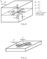
- each active site As a first order approximation of our system, we consider each active site to be surrounded by 4 passive sites ( Figure 6 ). By describing each active and passive site as a single thermal block, it is possible to draw a circuit diagram that describes an electrical model of the thermal behaviour of an active site ( Figure 7 ), where “conductor” or “conductive site” refers to the passive thermal region 8 and “insulator” or “insulating site” refers to the active thermal site 6, and:
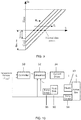
- Figure 9 plots heat flow into the fluid (q fi ), for several constant values of fluid temperature.
- the heat flow from the insulator into the fluid (q fi ) is negative: i.e. the active site cools the fluid.
- the maximum amount of cooling provided by the active site is tuned by the thermal resistance R iz of the thermal insulation layer 16 between the active site and the heat sink in the direction perpendicular to the plane of the substrate, and therefore that resistance R iz is a key design parameter for the active site.
- the bias point where the heat q from the heater exactly counteracts the loss of heat to the substrate 10 and surrounding passive regions 8 decreases with increasing insulator thermal resistance R iz .
- the insulator resistance R iz can be tuned to change the balance between heating and cooling at the active thermal sites 6.
- the minimum available cooling power which occurs when the heater is off and the temperature of the fluid is at a minimum, is set by the heatsink temperature and the thermal resistance of the site.
- the heatsink temperature is held at unrealistically low values, the amount of heat flowing through the site increases with the temperature of the fluid, i.e. q HS,max >> q HS,min .
- This inefficiency ultimately limits the cooling power that can be applied by the active site, because of the finite capacity of the heatsink to remove the waste heat. This is why providing the passive sites for pre-cooling the fluid between active sites enables more efficient heating and a larger temperature range for a given amount of heater power.
- thermofluidic chip described here has intrinsic non-linearity caused by the variable temperature of the fluid above the active sites.
- a thermal control system see Figure 10 , which includes a non-linear control function ("lineariser") in order to achieve the necessary temperature control.
- lineariser non-linear control function
- the electrical current passing through the heater 13 can be controlled in order to maintain a constant temperature in the fluid.
- FIG 10 shows the feedback loop for a single active site 6.
- Each active site 6 may have a separate instance of such a feedback loop.
- the target temperature T target is input to a controller 30 which also receives the temperature T i measured by the temperature sensor 14 of the corresponding active site.
- the controller 30 determines the target amount of heat q fi to be supplied by the active site 6 to the fluid based on a transfer function of the form C(s).(T target - T i ), where C(s) is a transfer function whose poles and zeros have been placed according to classical control theory.
- a lineariser 32 comprises mapping circuitry which maps the target amount of heat q wi supplied by the controller 30 to an input signal I defining the amount of current to be supplied by a current driver 34 to the heater 13, in dependence on T i and T HS , the temperature of the substrate 10.
- the substrate temperature T HS can be measured by a single sensor 36 shared between all active sites 6 or by individual sensors local to each active site 6.
- the lineariser 32 provides a non-linear mapping function which enables the controller 30 to use a linear transfer function (hence the term "lineariser”).
- the non-linear function provided by the lineariser 32 may be a function representing an analytic inversion of the thermal model.
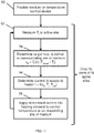
- FIG 11 is a flow diagram illustrating the temperature control method.
- the medium in which the temperature is to be controlled is provided on the temperature control device.
- the medium can be a fluid flowing over the temperature control device.
- the temperature T i is measured at an active thermal site 6.
- step 58 the determined amount of current I is supplied to the heating element 13 by the current driver 34 to control the temperature at the corresponding site of the medium.
- the method then returns to step 52 to continue to control the temperature at the site based on the measured temperature T i and target temperature T target , taking into account the heat flow from the active site 6 to regions other than the medium itself according to the thermal model discussed above.
- Steps 52 to 58 are performed N times in parallel, once for each active site in the temperature control device 2.
- the required thermal resistances of the active and passive regions 6, 8 are determined, so that suitable materials and geometries can be chosen. There are two conditions which a 3D block of an active site should meet:
- One way to satisfy the condition for small heat leakage between sites is to, by patterning, make the active site material thermally anisotropic.
- the active site material thermally anisotropic.
- one can produce a structure where vertical pillars of SiO 2 are separated by spaces of air (k air 0.024 W/m/K).
- the required vertical height of the material in this case the height of the pillars, is multiplied by the pillar fill factor.
- the insulating pillars may take a number of different geometries, several examples of which are shown in Figure 12 .
- the pillars 60 are surrounded by voids comprising air, gas or vacuum. In other examples the pillars could enclose the voids.
- a pillared structure comprising pillars extending in the direction perpendicular to the substrate and voids around or between the pillars, we maintain the same thermal resistance in the vertical direction (R iz ⁇ 27,000 K/W) but it is clear that the lateral resistance is reduced, mainly because k air ⁇ k SiO2 but also because of the lower height of the active material.
- the lateral thermal resistance can be further increased by reducing the pillar height, and simultaneously reducing the fill-factor.
- the silicon pillars can be separated by vacuum, providing a significant further increase in lateral resistance.
- thermal insulator to consist of insulating pillars separated by air (or vacuum) provides a method of satisfying the thermal conditions of an active site.
- the limit of this case (where fill-factor goes to zero and the void covers the entire area of the active site) results in a free standing membrane which can be considered as an alternative approach to satisfying the thermal requirements.
- Figure 13 shows how the pillared approach can be integrated into a complete device.
- the figure shows a cross-section through the device substrate, passing through two active and several passive thermal sites.
- Silicon 70 is shown using vertical hatching, silicon dioxide 72 using diagonal hatching, and the metal layers 74 are shown using horizontal hatching.
- the voids are shown in white. Note that the figure is not to scale, the upper layers are shown magnified in the vertical direction.
- Silicon provides a highly thermally conducting material for the substrate and is capable of being thermally oxidised in order to produce thermally insulating pillars 60 with voids 62 between the pillars.
- On top of the substrate containing the pillar structure there are a number of layers which contain the heater; a heat spreader (to evenly distribute the heat produced); a thermometer (to enable thermal control); and a surface capping layer.
- the device 2 of Figure 13 can be built using processes available to the silicon CMOS and silicon MEMS industries.
- Figures 14 and 15 show a process flow which achieves the required thermal resistances in the passive and active regions.
- the process starts with a silicon-on-insulator (SOI) wafer 100 comprising a relatively thick silicon handle 102, a buried oxide layer 104, and a silicon device layer 106.
- SOI silicon-on-insulator
- the thickness of the silicon device layer 106 gives the height of the silicon dioxide pillars and the thickness of the buried oxide is approximately 1 ⁇ m. Since a second wafer is later used in the processing, we refer to the SOI wafer as the 'primary'.
- the surface of the primary wafer 100 at which the device layer 106 is formed is referred to below as the 'first surface'.
- the primary wafer 100 is photolithographically patterned and, using photoresist as an etch mask, the silicon device layer 106 is anisotropically etched down to the buried oxide 104 to form holes 108.
- a deep reactive ion etch is used.
- the wafer is oxidised, giving a thermal oxide with thickness of approximately 1 ⁇ m for example.
- the edges of the holes 108 are oxidised to form the walls of the silicon dioxide pillars 110.
- a secondary wafer 120 is provided.
- the secondary wafer 120 comprises a processed CMOS wafer, containing the electrically active and electrically passive devices needed for the heating and control functionality (e.g. the heater 13, temperature sensor 14, and upper parts of the thermal conductor layer of the passive sites 8). These metal layers and the devices within the secondary CMOS wafer 120 are not shown in Figure 15 but can be provided as shown in Figure 13 .
- the primary wafer 100 is turned upside down and the first surface of the primary wafer 100 is bonded to the secondary wafer 120.
- the wafer bonding could be achieved by thermo-compression bonding, in which case metal (e.g. gold) layers are needed on the surface of both the primary and secondary wafers.
- step 90 the backside of the bonded primary wafer (the original handle layer 102 of the SOI wafer) is etched back to leave the buried oxide 104 of that SOI wafer 100 as at the top of the stack.
- metal tracks for the heater/thermometer/heat-spreader stack can be built on the secondary wafer 120 (not shown in Figure 15 ).
- etch holes 122 are photolithographically patterned and etched in the top silicon dioxide layer 104. Then, in a subsequent process step 94 (part g of Figure 15 ), an anisotropic dry etch (e.g. with XeF 2 ) of these silicon regions is performed, to form the voids 124 by etching away parts of the silicon device layer 106 via the etch holes 122 in the oxide 104. At step 96, the etch holes 122 in the oxide layer 104 are filled with dielectric (part h of Figure 15 ), completing the processing of the active and passive thermal sites.
- dielectric part h of Figure 15
- the words “configured to" are used to mean that an element of an apparatus has a configuration able to carry out the defined operation.
- a “configuration” means an arrangement or manner of interconnection of hardware or software.
- the apparatus may have dedicated hardware which provides the defined operation, or a processor or other processing device may be programmed to perform the function.
- Configured to does not imply that the apparatus element needs to be changed in any way in order to provide the defined operation.
Landscapes
- Engineering & Computer Science (AREA)
- Physics & Mathematics (AREA)
- General Physics & Mathematics (AREA)
- Automation & Control Theory (AREA)
- Chemical & Material Sciences (AREA)
- Health & Medical Sciences (AREA)
- Remote Sensing (AREA)
- Biochemistry (AREA)
- Life Sciences & Earth Sciences (AREA)
- General Health & Medical Sciences (AREA)
- Molecular Biology (AREA)
- Clinical Laboratory Science (AREA)
- Chemical Kinetics & Catalysis (AREA)
- Control Of Temperature (AREA)
- Cooling Or The Like Of Semiconductors Or Solid State Devices (AREA)
- Control Of Resistance Heating (AREA)
Claims (9)
- Dispositif de régulation de température destiné à réguler des températures en une pluralité de sites d'un milieu, comportant :une pluralité de sites thermiques actifs (6) disposés à des emplacements respectifs sur un substrat (10), chaque site thermique actif comportant un élément chauffant (13) configuré pour appliquer une quantité variable de chaleur à un site correspondant dudit milieu et une couche (16) d'isolation thermique disposée entre l'élément chauffant et le substrat ; etune ou plusieurs régions thermiques passives disposées (8) entre la pluralité de sites thermiques actifs sur le substrat, chaque région thermique passive comportant une couche (18) de conduction thermique configurée pour conduire de la chaleur d'une partie correspondante du milieu au substrat ;la couche (18) de conduction thermique de ladite ou desdites régions thermiques passives présentant une plus faible résistance thermique dans une direction perpendiculaire à un plan du substrat que la couche d'isolation thermique de ladite pluralité de sites thermiques actifs ;caractérisé en ce que la couche (16) d'isolation thermique d'un site thermique actif donné comporte :un ou plusieurs piliers (60) d'un premier matériau d'isolation thermique s'étendant sensiblement perpendiculairement au plan du substrat dans la zone du site thermique actif entre l'élément chauffant et le substrat ; etun ou plusieurs vides disposés entre les piliers ou autour de ceux-ci.
- Dispositif de régulation de température selon l'une quelconque des revendications précédentes, chaque site thermique actif comportant un capteur (36) de température configuré pour détecter une température au niveau du site thermique actif correspondant.
- Dispositif de régulation de température selon la revendication 2, comportant une pluralité de boucles de réaction correspondant chacune à un site thermique actif respectif ;
chaque boucle de réaction étant configurée pour mettre en œuvre une fonction de transfert servant à déterminer une quantité cible de chaleur à appliquer au site correspondant du milieu en fonction de la température détectée par le capteur de température du site thermique actif correspondant et d'une température cible spécifiée pour le site correspondant du milieu. - Dispositif de régulation de température selon l'une quelconque des revendications précédentes, la couche d'isolation thermique de ladite pluralité de sites thermiques actifs présentant une résistance thermique plus élevée dans une direction parallèle au plan du substrat que dans une direction perpendiculaire au plan du substrat.
- Dispositif de régulation de température selon l'une quelconque des revendications précédentes, comportant un mécanisme (12) de refroidissement servant à refroidir le substrat pour agir comme un dissipateur de chaleur.
- Dispositif de régulation de température selon l'une quelconque des revendications précédentes, le milieu comportant un fluide, et le dispositif de régulation de température comportant un élément de régulation d'écoulement de fluide configuré pour réguler un écoulement du fluide par-dessus la pluralité de sites thermiques actifs et la ou les régions thermiques passives.
- Dispositif de régulation de température selon la revendication 6, les sites thermiques actifs étant disposés en une ou plusieurs rangées orientées sensiblement parallèlement à la direction d'écoulement de fluide régulé par l'élément de régulation d'écoulement de fluide ;
chaque rangée comportant au moins deux sites thermiques actifs, une région de refroidissement passif étant disposée entre chaque paire de sites thermiques actifs adjacents de la rangée. - Dispositif de régulation de température selon la revendication 7, chaque site thermique actif présentant une longueur suivant la direction des rangées qui est supérieure à une longueur suivant la direction des rangées de chaque région de refroidissement passif disposée entre des sites thermiques actifs adjacents de la rangée.
- Procédé de régulation de températures en une pluralité de sites d'un milieu, comportant les étapes consistant à :mettre en place le milieu sur un dispositif de régulation de température comportant une pluralité de sites thermiques actifs disposés à des emplacements respectifs sur un substrat et une ou plusieurs régions thermiques passives disposées entre la pluralité de sites thermiques actifs sur le substrat ;chaque site thermique actif comportant un élément chauffant configuré pour appliquer une quantité variable de chaleur à un site correspondant dudit milieu et une couche d'isolation thermique disposée entre l'élément chauffant et le substrat ;chaque région thermique passive comportant une couche de conduction thermique configurée pour conduire de la chaleur d'une partie correspondante du milieu au substrat ; etla couche de conduction thermique de ladite ou desdites régions thermiques passives présentant une plus faible résistance thermique dans une direction perpendiculaire à un plan du substrat que la couche d'isolation thermique de ladite pluralité de sites thermiques actifs ; etréguler la quantité de chaleur appliquée par les éléments chauffants de la pluralité de sites thermiques actifs pour réguler les températures sur ladite pluralité de sites du milieu ;caractérisé en ce que la couche d'isolation thermique d'un site thermique actif donné comporte :un ou plusieurs piliers d'un premier matériau d'isolation thermique s'étendant sensiblement perpendiculairement au plan du substrat dans la zone du site thermique actif entre l'élément chauffant et le substrat ; etun ou plusieurs vides disposés entre les piliers ou autour de ceux-ci.
Applications Claiming Priority (2)
| Application Number | Priority Date | Filing Date | Title |
|---|---|---|---|
| GB1620982.7A GB2557592A (en) | 2016-12-09 | 2016-12-09 | Temperature control device |
| PCT/GB2017/053297 WO2018104698A1 (fr) | 2016-12-09 | 2017-11-02 | Dispositif de régulation de température |
Publications (2)
| Publication Number | Publication Date |
|---|---|
| EP3551331A1 EP3551331A1 (fr) | 2019-10-16 |
| EP3551331B1 true EP3551331B1 (fr) | 2021-12-29 |
Family
ID=58222245
Family Applications (1)
| Application Number | Title | Priority Date | Filing Date |
|---|---|---|---|
| EP17795022.7A Active EP3551331B1 (fr) | 2016-12-09 | 2017-11-02 | Dispositif de régulation de température |
Country Status (12)
| Country | Link |
|---|---|
| US (1) | US11577251B2 (fr) |
| EP (1) | EP3551331B1 (fr) |
| JP (1) | JP7022130B2 (fr) |
| KR (1) | KR102488179B1 (fr) |
| CN (1) | CN110022981B (fr) |
| AU (1) | AU2017371801B2 (fr) |
| CA (1) | CA3042610C (fr) |
| GB (1) | GB2557592A (fr) |
| HU (1) | HUE057490T2 (fr) |
| IL (1) | IL266815B2 (fr) |
| TW (1) | TWI751231B (fr) |
| WO (1) | WO2018104698A1 (fr) |
Cited By (1)
| Publication number | Priority date | Publication date | Assignee | Title |
|---|---|---|---|---|
| WO2024245594A1 (fr) * | 2023-06-02 | 2024-12-05 | Ers Electronic Gmbh | Dispositif et procédé de test de plaquettes de semi-conducteurs |
Families Citing this family (13)
| Publication number | Priority date | Publication date | Assignee | Title |
|---|---|---|---|---|
| FR3032529B1 (fr) * | 2015-02-06 | 2019-06-07 | Saint-Gobain Isover | Determination de la resistance thermique d'une paroi |
| DE102018204378A1 (de) * | 2018-03-22 | 2019-09-26 | Audi Ag | Ermittlung des Isolationswiderstands eines Brennstoffzellensystems |
| GB2576304B (en) * | 2018-07-26 | 2020-09-09 | Evonetix Ltd | Accessing data storage provided using double-stranded nucleic acid molecules |
| TWI675287B (zh) | 2018-09-10 | 2019-10-21 | 群光電子股份有限公司 | 加熱散熱模組 |
| CN109484680B (zh) * | 2018-12-21 | 2021-12-14 | 深圳航天东方红卫星有限公司 | 一种基于三浦折叠的辐射热控机构 |
| CN113993624B (zh) * | 2019-06-21 | 2024-02-09 | 亚德诺半导体国际无限责任公司 | 热平台和制造热平台的方法 |
| DE102019122364A1 (de) * | 2019-08-20 | 2021-02-25 | Schreiner Group Gmbh & Co. Kg | Gegenstand zur Durchführung einer elektrischen Messung an einer Messschicht |
| JP2021096208A (ja) * | 2019-12-19 | 2021-06-24 | ソニーセミコンダクタソリューションズ株式会社 | 電位測定装置 |
| WO2021257151A1 (fr) * | 2020-06-19 | 2021-12-23 | Embr Labs Inc. | Systèmes thermoélectriques à faible puissance |
| KR102748381B1 (ko) * | 2021-12-30 | 2024-12-27 | 주식회사 수젠텍 | 인큐베이터 온도 제어 시스템 및 그의 제작방법 |
| CN114924041A (zh) * | 2022-05-20 | 2022-08-19 | 艾感科技(广东)有限公司 | 一种用于高灵敏度气体传感装置的加热装置 |
| GB2621385A (en) | 2022-08-11 | 2024-02-14 | Evonetix Ltd | Reaction duration control for reaction performed on biomolecule samples |
| GB202300626D0 (en) | 2023-01-16 | 2023-03-01 | Evonetix Ltd | Hybridisation detection |
Family Cites Families (28)
| Publication number | Priority date | Publication date | Assignee | Title |
|---|---|---|---|---|
| GB8900688D0 (en) * | 1989-01-12 | 1989-07-05 | Thorn Emi Electronics Ltd | Thermal imaging device |
| FI915731A0 (fi) * | 1991-12-05 | 1991-12-05 | Derek Henry Potter | Foerfarande och anordning foer reglering av temperaturen i ett flertal prov. |
| CA2082080A1 (fr) * | 1992-04-20 | 1993-10-21 | Gordon Walter Culp | Surface a plusieurs cavites thermocommandees individuellement |
| JPH0725047A (ja) | 1993-07-13 | 1995-01-27 | Graphtec Corp | サーマルヘッド |
| US5700715A (en) * | 1994-06-14 | 1997-12-23 | Lsi Logic Corporation | Process for mounting a semiconductor device to a circuit substrate |
| US5751315A (en) | 1996-04-16 | 1998-05-12 | Xerox Corporation | Thermal ink-jet printhead with a thermally isolated heating element in each ejector |
| JPH11339937A (ja) * | 1998-05-22 | 1999-12-10 | Komatsu Ltd | 温度制御装置、温度制御装置の製造方法、温度センサおよび温度センサの製造方法 |
| TW557527B (en) | 2001-03-26 | 2003-10-11 | Schlumberger Technologies Inc | Method and apparatus for calibration of integrated circuit tester timing |
| US6762049B2 (en) * | 2001-07-05 | 2004-07-13 | Institute Of Microelectronics | Miniaturized multi-chamber thermal cycler for independent thermal multiplexing |
| US20050233540A1 (en) * | 2004-04-15 | 2005-10-20 | Texas Instruments, Incorporated | Minimizing transistor variations due to shallow trench isolation stress |
| US6988826B2 (en) * | 2004-05-17 | 2006-01-24 | General Electric Company | Nano-calorimeter device and associated methods of fabrication and use |
| EP1637228A1 (fr) * | 2004-09-16 | 2006-03-22 | Roche Diagnostics GmbH | Procédé et dispositif pour réaliser des cyclages thermiques rapides et systeme microfluidique |
| TWI248667B (en) | 2004-11-25 | 2006-02-01 | Advanced Semiconductor Eng | Semiconductor package having heat pipes |
| US7691334B2 (en) * | 2005-09-20 | 2010-04-06 | Yamaha Corporation | Temperature control apparatus for microchemical chip |
| TWI338355B (en) | 2007-03-01 | 2011-03-01 | Advanced Semiconductor Eng | Buried electronic device structure and manufacturing method thereof |
| CN101641150B (zh) * | 2007-03-23 | 2014-05-07 | 皇家飞利浦电子股份有限公司 | 具有降低的峰值功耗的集成微流体器件 |
| EP1974816A1 (fr) * | 2007-03-23 | 2008-10-01 | Koninklijke Philips Electronics N.V. | Dispositif à microfluide intégré avec circuit intégré |
| EP1976034A3 (fr) * | 2007-03-29 | 2011-11-09 | Stichting IMEC Nederland | Procédé de fabrication d'une thermopile, thermopile ainsi obtenue et générateur thermoélectrique comportant de telles thermopiles |
| JP5675138B2 (ja) | 2010-03-25 | 2015-02-25 | 東京エレクトロン株式会社 | プラズマ処理装置 |
| CN202189788U (zh) * | 2011-08-26 | 2012-04-11 | 厦门市三安光电科技有限公司 | 一种阵列式发光二极管 |
| KR20150061678A (ko) * | 2013-11-27 | 2015-06-05 | 에스케이하이닉스 주식회사 | 수직형 반도체 장치 및 그 제조 방법 |
| TWI563780B (en) * | 2014-12-10 | 2016-12-21 | Ind Tech Res Inst | Power heat dissipation device and heat dissipation control method thereof |
| CN104626422B (zh) * | 2015-02-09 | 2017-05-24 | 辽宁奇点节能科技股份有限公司 | 一种单面传热压机热板 |
| WO2016197106A1 (fr) * | 2015-06-05 | 2016-12-08 | Miroculus Inc. | Gestion de l'évaporation dans des dispositifs microfluidiques numériques |
| TWI557527B (zh) * | 2015-12-28 | 2016-11-11 | 財團法人工業技術研究院 | 具儲熱元件的微機電溫度控制系統 |
| JP7104029B2 (ja) * | 2016-10-14 | 2022-07-20 | エフ.ホフマン-ラ ロシュ アーゲー | 試験要素支持体 |
| CN113993624B (zh) * | 2019-06-21 | 2024-02-09 | 亚德诺半导体国际无限责任公司 | 热平台和制造热平台的方法 |
| FR3103552B1 (fr) * | 2019-11-22 | 2021-12-10 | Commissariat Energie Atomique | procede de fabrication d’un dispositif de detection presentant une protection amelioree du getter |
-
2016
- 2016-12-09 GB GB1620982.7A patent/GB2557592A/en not_active Withdrawn
-
2017
- 2017-11-02 EP EP17795022.7A patent/EP3551331B1/fr active Active
- 2017-11-02 AU AU2017371801A patent/AU2017371801B2/en active Active
- 2017-11-02 CA CA3042610A patent/CA3042610C/fr active Active
- 2017-11-02 KR KR1020197018581A patent/KR102488179B1/ko active Active
- 2017-11-02 WO PCT/GB2017/053297 patent/WO2018104698A1/fr not_active Ceased
- 2017-11-02 US US16/461,913 patent/US11577251B2/en active Active
- 2017-11-02 HU HUE17795022A patent/HUE057490T2/hu unknown
- 2017-11-02 IL IL266815A patent/IL266815B2/en unknown
- 2017-11-02 CN CN201780074729.5A patent/CN110022981B/zh active Active
- 2017-11-02 JP JP2019530166A patent/JP7022130B2/ja active Active
- 2017-11-28 TW TW106141277A patent/TWI751231B/zh active
Non-Patent Citations (1)
| Title |
|---|
| None * |
Cited By (1)
| Publication number | Priority date | Publication date | Assignee | Title |
|---|---|---|---|---|
| WO2024245594A1 (fr) * | 2023-06-02 | 2024-12-05 | Ers Electronic Gmbh | Dispositif et procédé de test de plaquettes de semi-conducteurs |
Also Published As
| Publication number | Publication date |
|---|---|
| EP3551331A1 (fr) | 2019-10-16 |
| CN110022981A (zh) | 2019-07-16 |
| GB2557592A (en) | 2018-06-27 |
| KR102488179B1 (ko) | 2023-01-13 |
| US20190275527A1 (en) | 2019-09-12 |
| CA3042610A1 (fr) | 2018-06-14 |
| IL266815B1 (en) | 2023-07-01 |
| GB201620982D0 (en) | 2017-01-25 |
| TW201828422A (zh) | 2018-08-01 |
| CN110022981B (zh) | 2022-04-12 |
| WO2018104698A1 (fr) | 2018-06-14 |
| AU2017371801B2 (en) | 2022-06-30 |
| JP7022130B2 (ja) | 2022-02-17 |
| IL266815A (en) | 2019-07-31 |
| US11577251B2 (en) | 2023-02-14 |
| AU2017371801A1 (en) | 2019-06-06 |
| HUE057490T2 (hu) | 2022-05-28 |
| CA3042610C (fr) | 2024-01-16 |
| JP2020501271A (ja) | 2020-01-16 |
| IL266815B2 (en) | 2023-11-01 |
| KR20190093595A (ko) | 2019-08-09 |
| TWI751231B (zh) | 2022-01-01 |
Similar Documents
| Publication | Publication Date | Title |
|---|---|---|
| EP3551331B1 (fr) | Dispositif de régulation de température | |
| Briand et al. | Thermal optimization of micro-hotplates that have a silicon island | |
| Zhang et al. | Silicon microchannel heat sinks: theories and phenomena | |
| Silvério et al. | Design, fabrication and test of an integrated multi-microchannel heat sink for electronics cooling | |
| Zhang et al. | Experimental and numerical study of transient electronic chip cooling by liquid flow in microchannel heat sinks | |
| Goncalves et al. | On-chip array of thermoelectric Peltier microcoolers | |
| CN106064805B (zh) | 一种带恒温控制的热式驱动mems器件 | |
| Sahu et al. | Experimental characterization of hybrid solid-state and fluidic cooling for thermal management of localized hotspots | |
| Chen et al. | Onset of thermal convection in an anisotropic and inhomogeneous porous layer underlying a fluid layer | |
| Cai et al. | Design, development and tests of a compact thermofluid system | |
| HK40014024A (en) | Temperature control device | |
| HK40014024B (en) | Temperature control device | |
| JP2003180350A (ja) | 温度制御装置 | |
| Rightley et al. | Innovative wick design for multi-source, flat plate heat pipes | |
| Takács et al. | Improved thermal characterization method of integrated microscale heat sinks | |
| Eng et al. | An experimental study on an electro-osmotic flow-based silicon heat spreader | |
| Fonseca et al. | Use of boron heavily doped silicon slabs for gas sensors based on free-standing membranes | |
| CN116194218A (zh) | 微热循环仪 | |
| Bonnema et al. | Inline microfluidic thermal conductivity sensor using a suspended highly-doped silicon heater | |
| Wijngaards et al. | Single-chip micro-thermostat applying both active heating and active cooling | |
| Xie et al. | Seal and encapsulate cavities for complementary metal-oxide-semiconductor microelectromechanical system thermoelectric power generators | |
| Zhang et al. | An experimental study on the effect of configuration of multiple microchannels on heat removal for electronic cooling | |
| JPS6345847A (ja) | 極低温用温度計 | |
| Furmanczyk et al. | Multiphysics modeling of integrated microfluidic-thermoelectric cooling for stacked 3D ICs | |
| Yan et al. | Integrated thin film heater and sensor with planar lightwave circuits |
Legal Events
| Date | Code | Title | Description |
|---|---|---|---|
| STAA | Information on the status of an ep patent application or granted ep patent |
Free format text: STATUS: UNKNOWN |
|
| STAA | Information on the status of an ep patent application or granted ep patent |
Free format text: STATUS: THE INTERNATIONAL PUBLICATION HAS BEEN MADE |
|
| PUAI | Public reference made under article 153(3) epc to a published international application that has entered the european phase |
Free format text: ORIGINAL CODE: 0009012 |
|
| STAA | Information on the status of an ep patent application or granted ep patent |
Free format text: STATUS: REQUEST FOR EXAMINATION WAS MADE |
|
| 17P | Request for examination filed |
Effective date: 20190610 |
|
| AK | Designated contracting states |
Kind code of ref document: A1 Designated state(s): AL AT BE BG CH CY CZ DE DK EE ES FI FR GB GR HR HU IE IS IT LI LT LU LV MC MK MT NL NO PL PT RO RS SE SI SK SM TR |
|
| AX | Request for extension of the european patent |
Extension state: BA ME |
|
| DAV | Request for validation of the european patent (deleted) | ||
| DAX | Request for extension of the european patent (deleted) | ||
| STAA | Information on the status of an ep patent application or granted ep patent |
Free format text: STATUS: EXAMINATION IS IN PROGRESS |
|
| 17Q | First examination report despatched |
Effective date: 20200409 |
|
| 17Q | First examination report despatched |
Effective date: 20200513 |
|
| REG | Reference to a national code |
Ref country code: HK Ref legal event code: DE Ref document number: 40014024 Country of ref document: HK |
|
| 111Z | Information provided on other rights and legal means of execution |
Free format text: AL AT BE BG CH CY CZ DE DK EE ES FI FR GB GR HR HU IE IS IT LT LU LV MC MK MT NL NO PL PT RO RS SE SI SK SM TR Effective date: 20201109 |
|
| RAP1 | Party data changed (applicant data changed or rights of an application transferred) |
Owner name: EVONETIX LTD |
|
| GRAP | Despatch of communication of intention to grant a patent |
Free format text: ORIGINAL CODE: EPIDOSNIGR1 |
|
| STAA | Information on the status of an ep patent application or granted ep patent |
Free format text: STATUS: GRANT OF PATENT IS INTENDED |
|
| INTG | Intention to grant announced |
Effective date: 20210721 |
|
| GRAS | Grant fee paid |
Free format text: ORIGINAL CODE: EPIDOSNIGR3 |
|
| RIN1 | Information on inventor provided before grant (corrected) |
Inventor name: TEMPLE, STEPHEN Inventor name: JUNCU, VASILE DAN Inventor name: FERGUSON, ANDREW JAMES Inventor name: HAYES, MATTHEW JAMES |
|
| GRAA | (expected) grant |
Free format text: ORIGINAL CODE: 0009210 |
|
| STAA | Information on the status of an ep patent application or granted ep patent |
Free format text: STATUS: THE PATENT HAS BEEN GRANTED |
|
| AK | Designated contracting states |
Kind code of ref document: B1 Designated state(s): AL AT BE BG CH CY CZ DE DK EE ES FI FR GB GR HR HU IE IS IT LI LT LU LV MC MK MT NL NO PL PT RO RS SE SI SK SM TR |
|
| REG | Reference to a national code |
Ref country code: GB Ref legal event code: FG4D |
|
| REG | Reference to a national code |
Ref country code: CH Ref legal event code: EP |
|
| REG | Reference to a national code |
Ref country code: AT Ref legal event code: REF Ref document number: 1458278 Country of ref document: AT Kind code of ref document: T Effective date: 20220115 |
|
| REG | Reference to a national code |
Ref country code: IE Ref legal event code: FG4D |
|
| REG | Reference to a national code |
Ref country code: DE Ref legal event code: R096 Ref document number: 602017051633 Country of ref document: DE |
|
| REG | Reference to a national code |
Ref country code: NL Ref legal event code: FP |
|
| REG | Reference to a national code |
Ref country code: LT Ref legal event code: MG9D |
|
| PG25 | Lapsed in a contracting state [announced via postgrant information from national office to epo] |
Ref country code: RS Free format text: LAPSE BECAUSE OF FAILURE TO SUBMIT A TRANSLATION OF THE DESCRIPTION OR TO PAY THE FEE WITHIN THE PRESCRIBED TIME-LIMIT Effective date: 20211229 Ref country code: LT Free format text: LAPSE BECAUSE OF FAILURE TO SUBMIT A TRANSLATION OF THE DESCRIPTION OR TO PAY THE FEE WITHIN THE PRESCRIBED TIME-LIMIT Effective date: 20211229 Ref country code: FI Free format text: LAPSE BECAUSE OF FAILURE TO SUBMIT A TRANSLATION OF THE DESCRIPTION OR TO PAY THE FEE WITHIN THE PRESCRIBED TIME-LIMIT Effective date: 20211229 Ref country code: BG Free format text: LAPSE BECAUSE OF FAILURE TO SUBMIT A TRANSLATION OF THE DESCRIPTION OR TO PAY THE FEE WITHIN THE PRESCRIBED TIME-LIMIT Effective date: 20220329 |
|
| REG | Reference to a national code |
Ref country code: HU Ref legal event code: AG4A Ref document number: E057490 Country of ref document: HU |
|
| PG25 | Lapsed in a contracting state [announced via postgrant information from national office to epo] |
Ref country code: SE Free format text: LAPSE BECAUSE OF FAILURE TO SUBMIT A TRANSLATION OF THE DESCRIPTION OR TO PAY THE FEE WITHIN THE PRESCRIBED TIME-LIMIT Effective date: 20211229 Ref country code: NO Free format text: LAPSE BECAUSE OF FAILURE TO SUBMIT A TRANSLATION OF THE DESCRIPTION OR TO PAY THE FEE WITHIN THE PRESCRIBED TIME-LIMIT Effective date: 20220329 Ref country code: LV Free format text: LAPSE BECAUSE OF FAILURE TO SUBMIT A TRANSLATION OF THE DESCRIPTION OR TO PAY THE FEE WITHIN THE PRESCRIBED TIME-LIMIT Effective date: 20211229 Ref country code: HR Free format text: LAPSE BECAUSE OF FAILURE TO SUBMIT A TRANSLATION OF THE DESCRIPTION OR TO PAY THE FEE WITHIN THE PRESCRIBED TIME-LIMIT Effective date: 20211229 Ref country code: GR Free format text: LAPSE BECAUSE OF FAILURE TO SUBMIT A TRANSLATION OF THE DESCRIPTION OR TO PAY THE FEE WITHIN THE PRESCRIBED TIME-LIMIT Effective date: 20220330 |
|
| PG25 | Lapsed in a contracting state [announced via postgrant information from national office to epo] |
Ref country code: SM Free format text: LAPSE BECAUSE OF FAILURE TO SUBMIT A TRANSLATION OF THE DESCRIPTION OR TO PAY THE FEE WITHIN THE PRESCRIBED TIME-LIMIT Effective date: 20211229 Ref country code: SK Free format text: LAPSE BECAUSE OF FAILURE TO SUBMIT A TRANSLATION OF THE DESCRIPTION OR TO PAY THE FEE WITHIN THE PRESCRIBED TIME-LIMIT Effective date: 20211229 Ref country code: RO Free format text: LAPSE BECAUSE OF FAILURE TO SUBMIT A TRANSLATION OF THE DESCRIPTION OR TO PAY THE FEE WITHIN THE PRESCRIBED TIME-LIMIT Effective date: 20211229 Ref country code: PT Free format text: LAPSE BECAUSE OF FAILURE TO SUBMIT A TRANSLATION OF THE DESCRIPTION OR TO PAY THE FEE WITHIN THE PRESCRIBED TIME-LIMIT Effective date: 20220429 Ref country code: ES Free format text: LAPSE BECAUSE OF FAILURE TO SUBMIT A TRANSLATION OF THE DESCRIPTION OR TO PAY THE FEE WITHIN THE PRESCRIBED TIME-LIMIT Effective date: 20211229 Ref country code: EE Free format text: LAPSE BECAUSE OF FAILURE TO SUBMIT A TRANSLATION OF THE DESCRIPTION OR TO PAY THE FEE WITHIN THE PRESCRIBED TIME-LIMIT Effective date: 20211229 |
|
| PG25 | Lapsed in a contracting state [announced via postgrant information from national office to epo] |
Ref country code: PL Free format text: LAPSE BECAUSE OF FAILURE TO SUBMIT A TRANSLATION OF THE DESCRIPTION OR TO PAY THE FEE WITHIN THE PRESCRIBED TIME-LIMIT Effective date: 20211229 |
|
| PG25 | Lapsed in a contracting state [announced via postgrant information from national office to epo] |
Ref country code: IS Free format text: LAPSE BECAUSE OF FAILURE TO SUBMIT A TRANSLATION OF THE DESCRIPTION OR TO PAY THE FEE WITHIN THE PRESCRIBED TIME-LIMIT Effective date: 20220429 |
|
| REG | Reference to a national code |
Ref country code: DE Ref legal event code: R097 Ref document number: 602017051633 Country of ref document: DE |
|
| PG25 | Lapsed in a contracting state [announced via postgrant information from national office to epo] |
Ref country code: DK Free format text: LAPSE BECAUSE OF FAILURE TO SUBMIT A TRANSLATION OF THE DESCRIPTION OR TO PAY THE FEE WITHIN THE PRESCRIBED TIME-LIMIT Effective date: 20211229 Ref country code: AL Free format text: LAPSE BECAUSE OF FAILURE TO SUBMIT A TRANSLATION OF THE DESCRIPTION OR TO PAY THE FEE WITHIN THE PRESCRIBED TIME-LIMIT Effective date: 20211229 |
|
| PLBE | No opposition filed within time limit |
Free format text: ORIGINAL CODE: 0009261 |
|
| STAA | Information on the status of an ep patent application or granted ep patent |
Free format text: STATUS: NO OPPOSITION FILED WITHIN TIME LIMIT |
|
| 26N | No opposition filed |
Effective date: 20220930 |
|
| PG25 | Lapsed in a contracting state [announced via postgrant information from national office to epo] |
Ref country code: SI Free format text: LAPSE BECAUSE OF FAILURE TO SUBMIT A TRANSLATION OF THE DESCRIPTION OR TO PAY THE FEE WITHIN THE PRESCRIBED TIME-LIMIT Effective date: 20211229 |
|
| REG | Reference to a national code |
Ref country code: AT Ref legal event code: UEP Ref document number: 1458278 Country of ref document: AT Kind code of ref document: T Effective date: 20211229 |
|
| P01 | Opt-out of the competence of the unified patent court (upc) registered |
Effective date: 20230428 |
|
| PG25 | Lapsed in a contracting state [announced via postgrant information from national office to epo] |
Ref country code: MC Free format text: LAPSE BECAUSE OF FAILURE TO SUBMIT A TRANSLATION OF THE DESCRIPTION OR TO PAY THE FEE WITHIN THE PRESCRIBED TIME-LIMIT Effective date: 20211229 |
|
| REG | Reference to a national code |
Ref country code: CH Ref legal event code: PL |
|
| PG25 | Lapsed in a contracting state [announced via postgrant information from national office to epo] |
Ref country code: LI Free format text: LAPSE BECAUSE OF NON-PAYMENT OF DUE FEES Effective date: 20221130 Ref country code: CH Free format text: LAPSE BECAUSE OF NON-PAYMENT OF DUE FEES Effective date: 20221130 |
|
| PG25 | Lapsed in a contracting state [announced via postgrant information from national office to epo] |
Ref country code: LU Free format text: LAPSE BECAUSE OF NON-PAYMENT OF DUE FEES Effective date: 20221102 |
|
| PG25 | Lapsed in a contracting state [announced via postgrant information from national office to epo] |
Ref country code: CY Free format text: LAPSE BECAUSE OF FAILURE TO SUBMIT A TRANSLATION OF THE DESCRIPTION OR TO PAY THE FEE WITHIN THE PRESCRIBED TIME-LIMIT Effective date: 20211229 |
|
| PG25 | Lapsed in a contracting state [announced via postgrant information from national office to epo] |
Ref country code: MK Free format text: LAPSE BECAUSE OF FAILURE TO SUBMIT A TRANSLATION OF THE DESCRIPTION OR TO PAY THE FEE WITHIN THE PRESCRIBED TIME-LIMIT Effective date: 20211229 |
|
| PG25 | Lapsed in a contracting state [announced via postgrant information from national office to epo] |
Ref country code: MT Free format text: LAPSE BECAUSE OF FAILURE TO SUBMIT A TRANSLATION OF THE DESCRIPTION OR TO PAY THE FEE WITHIN THE PRESCRIBED TIME-LIMIT Effective date: 20211229 |
|
| PG25 | Lapsed in a contracting state [announced via postgrant information from national office to epo] |
Ref country code: TR Free format text: LAPSE BECAUSE OF FAILURE TO SUBMIT A TRANSLATION OF THE DESCRIPTION OR TO PAY THE FEE WITHIN THE PRESCRIBED TIME-LIMIT Effective date: 20211229 |
|
| PGFP | Annual fee paid to national office [announced via postgrant information from national office to epo] |
Ref country code: HU Payment date: 20251027 Year of fee payment: 9 |
|
| PGFP | Annual fee paid to national office [announced via postgrant information from national office to epo] |
Ref country code: NL Payment date: 20251124 Year of fee payment: 9 |
|
| PGFP | Annual fee paid to national office [announced via postgrant information from national office to epo] |
Ref country code: DE Payment date: 20251126 Year of fee payment: 9 |
|
| PGFP | Annual fee paid to national office [announced via postgrant information from national office to epo] |
Ref country code: GB Payment date: 20251119 Year of fee payment: 9 |
|
| PGFP | Annual fee paid to national office [announced via postgrant information from national office to epo] |
Ref country code: AT Payment date: 20251118 Year of fee payment: 9 |
|
| PGFP | Annual fee paid to national office [announced via postgrant information from national office to epo] |
Ref country code: IT Payment date: 20251120 Year of fee payment: 9 |
|
| PGFP | Annual fee paid to national office [announced via postgrant information from national office to epo] |
Ref country code: FR Payment date: 20251124 Year of fee payment: 9 |
|
| PGFP | Annual fee paid to national office [announced via postgrant information from national office to epo] |
Ref country code: BE Payment date: 20251124 Year of fee payment: 9 |
|
| PGFP | Annual fee paid to national office [announced via postgrant information from national office to epo] |
Ref country code: IE Payment date: 20251118 Year of fee payment: 9 Ref country code: CZ Payment date: 20251016 Year of fee payment: 9 |