EP3551345B1 - Dispositif pour l'impression d'une image sur la surface d'un sol - Google Patents
Dispositif pour l'impression d'une image sur la surface d'un sol Download PDFInfo
- Publication number
- EP3551345B1 EP3551345B1 EP17822540.5A EP17822540A EP3551345B1 EP 3551345 B1 EP3551345 B1 EP 3551345B1 EP 17822540 A EP17822540 A EP 17822540A EP 3551345 B1 EP3551345 B1 EP 3551345B1
- Authority
- EP
- European Patent Office
- Prior art keywords
- nozzle
- colorant
- image
- robot
- controller
- Prior art date
- Legal status (The legal status is an assumption and is not a legal conclusion. Google has not performed a legal analysis and makes no representation as to the accuracy of the status listed.)
- Active
Links
Images


Classifications
-
- B—PERFORMING OPERATIONS; TRANSPORTING
- B05—SPRAYING OR ATOMISING IN GENERAL; APPLYING FLUENT MATERIALS TO SURFACES, IN GENERAL
- B05B—SPRAYING APPARATUS; ATOMISING APPARATUS; NOZZLES
- B05B13/00—Machines or plants for applying liquids or other fluent materials to surfaces of objects or other work by spraying, not covered by groups B05B1/00 - B05B11/00
- B05B13/005—Machines or plants for applying liquids or other fluent materials to surfaces of objects or other work by spraying, not covered by groups B05B1/00 - B05B11/00 mounted on vehicles or designed to apply a liquid on a very large surface, e.g. on the road, on the surface of large containers
-
- B—PERFORMING OPERATIONS; TRANSPORTING
- B05—SPRAYING OR ATOMISING IN GENERAL; APPLYING FLUENT MATERIALS TO SURFACES, IN GENERAL
- B05B—SPRAYING APPARATUS; ATOMISING APPARATUS; NOZZLES
- B05B12/00—Arrangements for controlling delivery; Arrangements for controlling the spray area
- B05B12/02—Arrangements for controlling delivery; Arrangements for controlling the spray area for controlling time, or sequence, of delivery
- B05B12/04—Arrangements for controlling delivery; Arrangements for controlling the spray area for controlling time, or sequence, of delivery for sequential operation or multiple outlets
-
- B—PERFORMING OPERATIONS; TRANSPORTING
- B05—SPRAYING OR ATOMISING IN GENERAL; APPLYING FLUENT MATERIALS TO SURFACES, IN GENERAL
- B05B—SPRAYING APPARATUS; ATOMISING APPARATUS; NOZZLES
- B05B12/00—Arrangements for controlling delivery; Arrangements for controlling the spray area
- B05B12/08—Arrangements for controlling delivery; Arrangements for controlling the spray area responsive to condition of liquid or other fluent material to be discharged, of ambient medium or of target ; responsive to condition of spray devices or of supply means, e.g. pipes, pumps or their drive means
- B05B12/084—Arrangements for controlling delivery; Arrangements for controlling the spray area responsive to condition of liquid or other fluent material to be discharged, of ambient medium or of target ; responsive to condition of spray devices or of supply means, e.g. pipes, pumps or their drive means responsive to condition of liquid or other fluent material already sprayed on the target, e.g. coating thickness, weight or pattern
-
- B—PERFORMING OPERATIONS; TRANSPORTING
- B05—SPRAYING OR ATOMISING IN GENERAL; APPLYING FLUENT MATERIALS TO SURFACES, IN GENERAL
- B05B—SPRAYING APPARATUS; ATOMISING APPARATUS; NOZZLES
- B05B12/00—Arrangements for controlling delivery; Arrangements for controlling the spray area
- B05B12/08—Arrangements for controlling delivery; Arrangements for controlling the spray area responsive to condition of liquid or other fluent material to be discharged, of ambient medium or of target ; responsive to condition of spray devices or of supply means, e.g. pipes, pumps or their drive means
- B05B12/12—Arrangements for controlling delivery; Arrangements for controlling the spray area responsive to condition of liquid or other fluent material to be discharged, of ambient medium or of target ; responsive to condition of spray devices or of supply means, e.g. pipes, pumps or their drive means responsive to conditions of ambient medium or target, e.g. humidity, temperature position or movement of the target relative to the spray apparatus
-
- B—PERFORMING OPERATIONS; TRANSPORTING
- B05—SPRAYING OR ATOMISING IN GENERAL; APPLYING FLUENT MATERIALS TO SURFACES, IN GENERAL
- B05B—SPRAYING APPARATUS; ATOMISING APPARATUS; NOZZLES
- B05B13/00—Machines or plants for applying liquids or other fluent materials to surfaces of objects or other work by spraying, not covered by groups B05B1/00 - B05B11/00
- B05B13/002—Machines or plants for applying coating liquids or other fluent materials by inkjet
-
- B—PERFORMING OPERATIONS; TRANSPORTING
- B05—SPRAYING OR ATOMISING IN GENERAL; APPLYING FLUENT MATERIALS TO SURFACES, IN GENERAL
- B05B—SPRAYING APPARATUS; ATOMISING APPARATUS; NOZZLES
- B05B13/00—Machines or plants for applying liquids or other fluent materials to surfaces of objects or other work by spraying, not covered by groups B05B1/00 - B05B11/00
- B05B13/02—Means for supporting work; Arrangement or mounting of spray heads; Adaptation or arrangement of means for feeding work
- B05B13/04—Means for supporting work; Arrangement or mounting of spray heads; Adaptation or arrangement of means for feeding work the spray heads being moved during spraying operation
- B05B13/0431—Means for supporting work; Arrangement or mounting of spray heads; Adaptation or arrangement of means for feeding work the spray heads being moved during spraying operation with spray heads moved by robots or articulated arms, e.g. for applying liquid or other fluent material to three-dimensional [3D] surfaces
-
- B—PERFORMING OPERATIONS; TRANSPORTING
- B05—SPRAYING OR ATOMISING IN GENERAL; APPLYING FLUENT MATERIALS TO SURFACES, IN GENERAL
- B05B—SPRAYING APPARATUS; ATOMISING APPARATUS; NOZZLES
- B05B15/00—Details of spraying plant or spraying apparatus not otherwise provided for; Accessories
- B05B15/50—Arrangements for cleaning; Arrangements for preventing deposits, drying-out or blockage; Arrangements for detecting improper discharge caused by the presence of foreign matter
- B05B15/55—Arrangements for cleaning; Arrangements for preventing deposits, drying-out or blockage; Arrangements for detecting improper discharge caused by the presence of foreign matter using cleaning fluids
-
- B—PERFORMING OPERATIONS; TRANSPORTING
- B05—SPRAYING OR ATOMISING IN GENERAL; APPLYING FLUENT MATERIALS TO SURFACES, IN GENERAL
- B05B—SPRAYING APPARATUS; ATOMISING APPARATUS; NOZZLES
- B05B15/00—Details of spraying plant or spraying apparatus not otherwise provided for; Accessories
- B05B15/50—Arrangements for cleaning; Arrangements for preventing deposits, drying-out or blockage; Arrangements for detecting improper discharge caused by the presence of foreign matter
- B05B15/55—Arrangements for cleaning; Arrangements for preventing deposits, drying-out or blockage; Arrangements for detecting improper discharge caused by the presence of foreign matter using cleaning fluids
- B05B15/555—Arrangements for cleaning; Arrangements for preventing deposits, drying-out or blockage; Arrangements for detecting improper discharge caused by the presence of foreign matter using cleaning fluids discharged by cleaning nozzles
-
- B—PERFORMING OPERATIONS; TRANSPORTING
- B41—PRINTING; LINING MACHINES; TYPEWRITERS; STAMPS
- B41J—TYPEWRITERS; SELECTIVE PRINTING MECHANISMS, i.e. MECHANISMS PRINTING OTHERWISE THAN FROM A FORME; CORRECTION OF TYPOGRAPHICAL ERRORS
- B41J2/00—Typewriters or selective printing mechanisms characterised by the printing or marking process for which they are designed
- B41J2/005—Typewriters or selective printing mechanisms characterised by the printing or marking process for which they are designed characterised by bringing liquid or particles selectively into contact with a printing material
- B41J2/01—Ink jet
- B41J2/135—Nozzles
- B41J2/165—Prevention or detection of nozzle clogging, e.g. cleaning, capping or moistening for nozzles
- B41J2/16517—Cleaning of print head nozzles
- B41J2/16552—Cleaning of print head nozzles using cleaning fluids
-
- B—PERFORMING OPERATIONS; TRANSPORTING
- B41—PRINTING; LINING MACHINES; TYPEWRITERS; STAMPS
- B41J—TYPEWRITERS; SELECTIVE PRINTING MECHANISMS, i.e. MECHANISMS PRINTING OTHERWISE THAN FROM A FORME; CORRECTION OF TYPOGRAPHICAL ERRORS
- B41J3/00—Typewriters or selective printing or marking mechanisms characterised by the purpose for which they are constructed
- B41J3/28—Typewriters or selective printing or marking mechanisms characterised by the purpose for which they are constructed for printing downwardly on flat surfaces, e.g. of books, drawings, boxes, envelopes, e.g. flat-bed ink-jet printers
-
- B—PERFORMING OPERATIONS; TRANSPORTING
- B41—PRINTING; LINING MACHINES; TYPEWRITERS; STAMPS
- B41J—TYPEWRITERS; SELECTIVE PRINTING MECHANISMS, i.e. MECHANISMS PRINTING OTHERWISE THAN FROM A FORME; CORRECTION OF TYPOGRAPHICAL ERRORS
- B41J3/00—Typewriters or selective printing or marking mechanisms characterised by the purpose for which they are constructed
- B41J3/407—Typewriters or selective printing or marking mechanisms characterised by the purpose for which they are constructed for marking on special material
-
- G—PHYSICS
- G05—CONTROLLING; REGULATING
- G05D—SYSTEMS FOR CONTROLLING OR REGULATING NON-ELECTRIC VARIABLES
- G05D1/00—Control of position, course, altitude or attitude of land, water, air or space vehicles, e.g. using automatic pilots
- G05D1/02—Control of position or course in two dimensions
- G05D1/021—Control of position or course in two dimensions specially adapted to land vehicles
- G05D1/0231—Control of position or course in two dimensions specially adapted to land vehicles using optical position detecting means
- G05D1/0234—Control of position or course in two dimensions specially adapted to land vehicles using optical position detecting means using optical markers or beacons
- G05D1/0236—Control of position or course in two dimensions specially adapted to land vehicles using optical position detecting means using optical markers or beacons in combination with a laser
-
- G—PHYSICS
- G05—CONTROLLING; REGULATING
- G05D—SYSTEMS FOR CONTROLLING OR REGULATING NON-ELECTRIC VARIABLES
- G05D1/00—Control of position, course, altitude or attitude of land, water, air or space vehicles, e.g. using automatic pilots
- G05D1/02—Control of position or course in two dimensions
- G05D1/021—Control of position or course in two dimensions specially adapted to land vehicles
- G05D1/0268—Control of position or course in two dimensions specially adapted to land vehicles using internal positioning means
- G05D1/0272—Control of position or course in two dimensions specially adapted to land vehicles using internal positioning means comprising means for registering the travel distance, e.g. revolutions of wheels
-
- G—PHYSICS
- G05—CONTROLLING; REGULATING
- G05D—SYSTEMS FOR CONTROLLING OR REGULATING NON-ELECTRIC VARIABLES
- G05D1/00—Control of position, course, altitude or attitude of land, water, air or space vehicles, e.g. using automatic pilots
- G05D1/02—Control of position or course in two dimensions
- G05D1/021—Control of position or course in two dimensions specially adapted to land vehicles
- G05D1/0276—Control of position or course in two dimensions specially adapted to land vehicles using signals provided by a source external to the vehicle
- G05D1/0278—Control of position or course in two dimensions specially adapted to land vehicles using signals provided by a source external to the vehicle using satellite positioning signals, e.g. GPS
-
- B—PERFORMING OPERATIONS; TRANSPORTING
- B05—SPRAYING OR ATOMISING IN GENERAL; APPLYING FLUENT MATERIALS TO SURFACES, IN GENERAL
- B05B—SPRAYING APPARATUS; ATOMISING APPARATUS; NOZZLES
- B05B9/00—Spraying apparatus for discharge of liquids or other fluent material, without essentially mixing with gas or vapour
- B05B9/03—Spraying apparatus for discharge of liquids or other fluent material, without essentially mixing with gas or vapour characterised by means for supplying liquid or other fluent material
- B05B9/04—Spraying apparatus for discharge of liquids or other fluent material, without essentially mixing with gas or vapour characterised by means for supplying liquid or other fluent material with pressurised or compressible container; with pump
- B05B9/0403—Spraying apparatus for discharge of liquids or other fluent material, without essentially mixing with gas or vapour characterised by means for supplying liquid or other fluent material with pressurised or compressible container; with pump with pumps for liquids or other fluent material
- B05B9/0413—Spraying apparatus for discharge of liquids or other fluent material, without essentially mixing with gas or vapour characterised by means for supplying liquid or other fluent material with pressurised or compressible container; with pump with pumps for liquids or other fluent material with reciprocating pumps, e.g. membrane pump, piston pump, bellow pump
Definitions
- the invention relates to a device such as an autonomous mobile robot or a remote-controlled vehicle for printing images pixel by pixel on ground surfaces.
- the object on which the invention is based is consequently to develop a device and a method that allows images to be applied over a large area Floor areas such as grass, snow, asphalt or gravel surfaces are inexpensive, quick and reliable.
- the device comprises a controller and a printing system.
- the printing system has at least one ink tank with ink and at least one spray bar with several nozzle assemblies arranged next to one another.
- the nozzle assemblies each have a valve that can be controlled by the controller and a paint nozzle that can be used to apply paint to the floor surface.
- the printing system also has a cleaning agent tank which is connected to at least some of the nozzle assemblies via one or more feed lines.
- Each of the nozzle assemblies has a cleaning nozzle, which is supplied via the supply line and is assigned to the respective paint nozzle, which is arranged such that cleaning agent can be sprayed onto the paint nozzle from the outside.
- the paint nozzle is connected to the supply line via a valve so that cleaning agent can be directed into the interior of the paint nozzle and sprayed out of the paint nozzle.
- a method for printing an image on a floor surface by means of a device which, according to an exemplary embodiment, has a printing system which comprises at least one spray bar with a plurality of nozzle assemblies arranged next to one another.
- the nozzle assemblies in turn each have a controllable valve and a paint nozzle.
- the printing system also has a cleaning agent tank which is connected to at least some of the nozzle assemblies via one or more feed lines.
- Each of the nozzle assemblies has a cleaning nozzle that is supplied via the supply line and assigned to the respective paint nozzle.
- the paint nozzle is connected to the supply line via a valve.
- the method comprises traversing a first path segment with the mobile robot and activating the valves of the nozzle assemblies to dispense paint through a paint nozzle assigned to the valve. For each pixel, and each color, depending on the position of the robot, generates a pressure command for the valves, so that the image is applied pixel by pixel on the floor surface.
- the method further comprises the regular cleaning of the paint nozzles by spraying cleaning agent onto the paint nozzles from the outside by means of the cleaning nozzles arranged in the nozzle assemblies and the regular cleaning of the paint nozzles by guiding them inside the paint nozzle and spraying cleaning agent out of the paint nozzle.
- One embodiment relates to a cleaning method for cleaning the nozzle assemblies of a spray bar, each nozzle assembly having a paint nozzle and a cleaning nozzle assigned to it.
- the method comprises supplying detergent to the cleaning nozzle so that detergent emerges from the cleaning nozzle and is sprayed onto the paint nozzle from the outside and supplying detergent inside the paint nozzle so that the detergent emerges from the paint nozzle.
- Figure 1 illustrates an example of a robot 100 for pixel-by-pixel printing of floor areas on the basis of a schematic top view.
- the robot 100 has a housing 101 which can be mechanically connected to at least a chassis or can be arranged on it.
- the running gear has a chain drive with the two chains 102 and 103.
- the robot can also have wheels. A combination of chains and wheels is also possible.
- the chains or the wheels are driven, for example, by an electric motor that is supplied with energy via a battery arranged in the robot 100.
- an electric motor that is supplied with energy via a battery arranged in the robot 100.
- At least one colorant container e.g. paint tanks 110, 111 and 112
- a cleaning agent container cleaning agent tank 113
- an electrical converter 116 current / voltage converter
- the controller 117 can be designed to receive control commands with the aid of an antenna 118 or to send status information (for example about a charge level of the battery or the progress of the printing process).
- the antenna 118 can be a WLAN antenna, for example.
- the converter 116 is, for example, a DC / DC converter for converting the battery voltage into the operating voltage (e.g. 24 V) required for the operation of the robot.
- the paint tanks 110, 111 and 112 and the detergent tank 113 can be replaceable plastic containers. For a quick exchange of the tanks, they can be attached to the housing (directly or indirectly), e.g. with quick-change fasteners.
- the controller 117 can be designed to autonomously navigate the robot over the floor area.
- the controller 117 can move the robot in accordance with control commands received from a remote controller operated by an operator.
- the controller can provide driver assistance functions that enable at least partially automatic navigation of the device.
- Statutory regulations may require a driver to ride with the vehicle.
- the device or the robot moves along a trajectory.
- the path of the robot can be divided into several path segments in which the trajectory can run essentially in a straight line. When driving through one of these path segments, several image lines of a partial image of the image to be printed are printed pixel by pixel on the floor surface.
- the device / the robot 100 can have sensors for determining its own position (location and location).
- the sensors for determining the position can be based on different measuring principles, for example odometry (e.g. using one or more wheel rotation sensors), camera-based odometry, position determination using GPS (e.g. differential GPS), etc.
- 201, 202, 203 which are also referred to as spray bars.
- the boom 120 holds the spray bars 201, 202, 203 at a defined distance above the surface to be printed. This distance can be adjustable.
- the robot can, for example, have an actuator (not shown) that can pivot the boom 120 and thus raise or lower the spray bars 201, 202, 203.
- the spray bars 201, 202, 203 can be separate components or can also be connected to form one component.
- At least one nozzle assembly 210 may be attached to the second end of the lift arm 120.
- Five nozzle assemblies 210 can form a nozzle module, and multiple nozzle modules can each form a nozzle bar 201, 202, or 203.
- the robot 100 has three nozzle bars 201, 202 and 203, each with 40 nozzle assemblies.
- Each spray bar can consist of one or more spray modules, with each spray module having a plurality of nozzles through which paint can be sprayed onto the floor surface.
- Each nozzle colors exactly one pixel of the image to be printed with a certain color. In the case of multi-color printing, each pixel of the image to be printed is colored accordingly several times with different colors.
- a spray bar comprises eight spray modules with five nozzles each, so that a spray bar has forty nozzles and consequently can color forty pixels in a row at the same time.
- the robot 100 is shown from below.
- the three spray bars 201, 202 and 203 with nozzles 210, 220 or 230 are shown.
- the distance between two adjacent nozzles corresponds to the pixel pitch (pixel pitch).
- the spray bars 201, 202 and 203 are arranged parallel to one another, so that three parallel rows are formed by nozzles, wherein the nozzles 210, 220, 230 can each be arranged along a longitudinal axis 201a, 202a, 203a of the respective spray bar 201, 202, 203.
- the distance a between two adjacent spray bars can be an integral multiple of the distance between two adjacent nozzles (ie the pixel distance). In an exemplary implementation, the distance a is equal to five times the pixel pitch.
- Figure 3 is a schematic front view of the robot 100.
- the robot 100 stands with the chains 102 and 103 of the chain drive on a floor surface 1 which is to be printed during operation while the robot moves over the floor surface.
- the floor area 1 to be printed can be of almost any configuration, for example a lawn, an asphalt floor, a snow-covered slope, etc.
- the floor area does not have to be flat.
- only the spray bar 201 can be seen (it covers the spray bars 202 and 203 located behind it).
- paint can be applied pixel by pixel to the floor surface 1 while the robot 100 is moving over it.
- each individual pixel can be colored with a specific color by means of subtractive color mixing.
- the spray bar 201 can be supplied with magenta colorant, the spray bar 202 with yellow colorant and the spray bar 203 with cyan colorant.
- the individual pixels with a defined position on the floor area 1 can be colored successively magenta, yellow and cyan.
- the amount of dye dispensed via the individual nozzles can be controlled.
- the ratio of the amounts of color magenta / yellow / cyan determines the hue and the absolute amount of color determines the color saturation.
- a fourth spray bar with black or white color can also be used. More than three spray bars can also be provided in order to implement multi-color printing, for example five spray bars for the colors cyan, magenta, yellow, black and white, in order to enable color mixing according to the CMYK color model (depending on the color of the floor area, a white color may be necessary).
- the printing system 200 of the robot 100 is exemplified in FIG Fig. 4 shown.
- the printing system includes the spray bars 201, 202, 203, the ink tanks 110, 111, 112, the cleaning agent tank 113, diaphragm pumps 250, 251, 252, 253 for conveying the colors from the ink tanks and the cleaning agent from the cleaning agent tank, overflow valves 260, 261, 262, 263, and the connecting lines that connect the individual components.
- the diagram in Fig. 4 shows, similar to a signal flow diagram, the supply of the spray bars 201, 202, 203 with colorant from the paint tanks 110, 111, 112 as well as with detergent from the detergent tank 113.
- the diaphragm pumps 250, 251, 252 convey colorant from the paint tanks 110, 111, 112 to the spray bars 201, 202, 203 (or to the spray modules from which the spray bars can be composed).
- the structure of the spray bars or individual spray modules will be explained in more detail later.
- the present example is suitable for three-color printing. For a print with four, five or more colors, more ink tanks and spray bars can be provided accordingly.
- the suction sides of the diaphragm pumps 250, 251 and 252 are hydraulically connected to the paint tanks 110, 111, 112, the pressure sides to the spray bars 201, 202, 203.
- overflow valves 260, 261, 262 can be arranged between the pressure sides of the diaphragm pumps 250, 251, 252 and the paint tanks 110, 111, 112 overflow valves 260, 261, 262 can be arranged. Excess paint can be fed back into the respective paint tank via the overflow valves 260, 261, 262. This can be the case when the diaphragm pumps deliver more paint than is dispensed via the spray bar. In this way, the overflow valves 260, 261, 262 can prevent the diaphragm pumps 250, 251, 252 from being overloaded.
- the diaphragm pumps 250, 251 and 252 can also have pulsation dampers, which ensure a uniform delivery of the colorant from the color tanks.
- the delivery of cleaning agent from the cleaning agent tank 113 to the spray bars 201, 202, 203 can be implemented in the same way as the delivery of paint.
- the diaphragm pumps 250, 251, 252 for delivering paint from the paint tanks also applies to the diaphragm pump 253 for delivering detergent from the detergent tank 113.
- the diaphragm pump 253 can also be equipped with an overflow valve 263 can be combined in order to prevent the diaphragm pump 253 from being overloaded and to guide excess detergent back into the detergent tank 113.
- other types of pumps can also be used. Pressure systems that manage without pumps are also possible.
- the paint tanks could be under Pressure can be set (e.g. by means of compressed air).
- the printing system 200 must contain components which are designed to provide the spray bar (or the individual spray modules) with paint and cleaning agent at a defined pressure.
- the individual paint nozzles 210 are arranged in the spray bar 201 (see also Fig. 2 ), each paint nozzle 210 being assigned to an assembly 211 (nozzle assembly) which contains a valve 212 for controlling the amount of paint to be dispensed via the paint nozzle 210, a cleaning nozzle 214 and a check valve 215 which enables the supply of cleaning agent to the paint nozzle 210, however prevents paint from flowing off to the feed line 217 for the cleaning agent.
- An exemplary structure of the nozzle assembly 211 mentioned is shown in FIG Figure 5 shown.
- the nozzle assembly 211 can also be constructed differently.
- the separate cleaning nozzle 214 is not absolutely necessary and external cleaning of the paint nozzle 210 is not necessary.
- the check valve 215 can be omitted and the cleaning of the paint nozzle 210 only takes place from the outside.
- the nozzle assembly 211 has a supply line 216 for paint and a supply line 217 for cleaning agent.
- Colorant 10 can be fed from one of the colorant containers 110, 111 and 112 to the nozzle assembly 210 via the supply line 216.
- Water 11 can be fed from the water tank 113 to the nozzle assembly 210 via the feed line 217.
- the feed line 216 is hydraulically connected to the inlet of the paint nozzle 210, for example via a controllable valve 212.
- the valve 212 can be an electromechanically controllable 2/2-way valve (for example a solenoid valve) and can control the amount of paint dispensed via the paint nozzle 210.
- the inlet of the cleaning agent nozzle 214 can be connected to the cleaning agent container 213 via the feed line 217 and can be supplied with cleaning agent 11 by this.
- the cleaning agent nozzle 214 can be directed at the colorant nozzle 211, so that the cleaning agent 11 exiting from the cleaning agent nozzle 214 is sprayed from the outside onto the paint nozzle 210 and this is cleaned of paint residues.
- the inlet of the paint nozzle 210 can also be connected to the supply line 217 via the check valve 215, so that the cleaning agent 11 is also used during cleaning flows through the paint nozzle 210 and cleans it inside.
- the check valve 215 prevents the ink from flowing to the feed line 217 for the cleaning agent.
- FIG. 6 shows a schematic structure of a spray module.
- the spray bars 201, 202, 203 can each be constructed from one or more spray modules.
- the spray module has five nozzle assemblies 211 (each with a paint nozzle 210) that are hydraulically connected to the paint containers 110, 111 and 112 and the water container 113 via a distributor unit 300.
- the distributor unit 300 can be a metallic, cuboid-shaped block that has a plurality of bores, some of which are hydraulically connected to one another.
- the distributor unit 300 can have at least one inlet 331, one outlet 332, one or more outlets 310 and one outlet 320.
- the inlet 331 is hydraulically connected to one of the colorant tanks 110, 111 and 112.
- the inlet 332 is hydraulically connected to the water tank 113.
- the manifold block 300 connects the inlet 331 for paint to the outlets 310, and the inlet 332 for detergent to the outlet 320.
- the outlets 310 can also be designed as seats for the nozzle assemblies 211. According to one example, the paint nozzles 10 of the nozzle assemblies 211 can be screwed into the outlets 310.
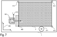
- FIG. 3 is a plan view of a floor surface 1 on which the robot 100 is located, a portion of the floor surface being printed with an image 2.
- Fig. 7 serves to illustrate the printing process carried out with the aid of the robot 100.
- the robot 100 can first be positioned at a starting point 400 and oriented in a desired direction.
- the starting point 400 can be a corner point of the image 2.
- the robot 100 is positioned with a corner of the foremost spray bar 201 at the starting point 400.
- the position of the robot 100 can be defined as the position of the rightmost paint nozzle 210 of the foremost spray bar 201.
- the image 2 to be printed can initially be present as a raster graphic that is stored electronically in an image file.
- Any common file format e.g. JPEG File Interchange Format (JFIF), Portable Network Graphics (PNG), Tagged Image File Format (TIFF), etc.
- JFIF JPEG File Interchange Format
- PNG Portable Network Graphics
- TIFF Tagged Image File Format
- the image file is then using software (Resizer software) in Image data which can be further processed by the robot 100 are converted and stored in a machine-readable file.
- a color separation is carried out first. This means that the color data contained in the image file (e.g. red, green and blue values with 8 bits each for 24 bit color depth) for the individual pixels are converted into corresponding amounts of color of the colorants used (in the colorant containers 110, 111 and 112).
- the raster graphics are also scaled to the required size. The number of pixels is adjusted so that the pixel spacing corresponds to the spacing of the paint nozzles 210 in the spray bar of
- the communication interface can be a USB interface, for example.
- a wireless transmission for example via a WLAN module integrated in the robot 100, is possible.
- other wireless connections e.g. Bluetooth, ZigBee, etc.
- the controller 117 of the robot can, for example, be designed to calculate a travel path of the robot 100 (robot path, trajectory) from the image data and then to control the chassis of the (e.g. chains 102 and 103) with appropriate travel commands so that the robot follows the calculated robot path follows.
- the controller 117 can also generate control commands for the diaphragm pumps 250, 251, 252 and 253 and for the valves 212 in the robot 100 from the image data.
- the amount of paint applied to the floor surface 1 is controlled directly via the valves 212.
- the coordinates x r t and y r t denotes the location of the robot 100 in the global coordinate system of the robot 900 and ⁇ r t the orientation of the robot (angle between the x-axis of the global coordinate system 900 and a local coordinate system 910 moved with the robot).
- Sensor data recorded by the robot are generally available in the local coordinate system 910 of the robot and can be transformed into the global coordinate system via a coordinate transformation.
- the robot 100 has a certain (global) position x ⁇ r t has reached a print command b x ⁇ r t and paint is applied to the floor surface 1 via the spray bars 201, 202, 203. While the robot moves along the previously calculated (eg meandering) path, the image is "printed" 2 pixel by pixel on the floor surface.
- the robot 100 can move along a straight trajectory of a straight path segment, practically any number of image points (pixels) can be printed along an image line, whereby as many image lines can be printed simultaneously as a spray bar has color nozzles (in the examples described above, these are 40 paint nozzles).
- the color nozzles can be controlled (print commands b x ⁇ r t ).
- the robot 100 must regularly determine its position (including orientation) in the global coordinate system 900. This process is also known as localization.
- the robot 100 can evaluate sensor data from one or more sensors.
- One possible method for locating the robot 100 is odometry.
- the robot determines its position based on the distance covered, which in turn can be determined using a rotary encoder on the (chain) wheels, for example. Odometry for determining the position and orientation of mobile robots in a coordinate system is known per se and is therefore not explained further here.
- Odometry based on encoder sensor data is only accurate over short distances and the position determined by the robot can drift away from the actual position (e.g. due to slippage).
- other sensors can be used that implement other measuring principles, such as a camera for camera-based odometry, distance sensors such as laser scanners for SLAM ( Simultaneous Localization on Mapping ), receivers for satellite-based positioning (e.g. GPS location and DGPS location).
- the controller 117 of the robot can be designed to merge sensor data from different sensors (sensor data fusion).
- the means Odometry (by means of rotary encoder) determined position can be regularly corrected based on the sensor data of other sensors (e.g. DGPS receiver).
- the robot can also detect landmarks by means of distance sensors (for example laser scanners), measure the position of the robot 100 relative to the detected landmarks (for example by means of triangulation), and use the position thus determined to correct the odometry.
- Landmarks are generally objects with a known position. In Fig. 7 objects 911 (eg a tree) and objects 912 (eg marker poles with reflectors) are shown.
- the positions of the objects 911 and 912 can be stored by the robot 100 in an electronic map.
- the map can also contain the positions of the individual pixels of the image 2 to be printed.
- the robot controller can generate a print command which activates the valves 212 in the spray bar accordingly.
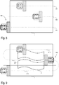
- Figure 8 shows an example of a possible path (trajectory) along which the robot moves when printing image 2.
- the robot path can have several straight path segments 401, 402 and 403, which the robot traverses sequentially.
- the robot 100 moves along the path segments 401, 402 and 403 over the floor area 1.
- Each of the path segments 401, 402 and 403 is driven over in the same direction.
- the robot 100 travels at the end of each path segment 401, 402 to the beginning of the respective next path segment 402, 403.
- the robot path also consists of parallel, straight path segments 611, 612 and 613. Unlike in the previous example, the robot travels through path segments 611, 612 and 613 in a meandering manner.
- the printing method performed by the robot 100 is summarized below. First, the robot 100 is parked at the starting point 400 (cf. Fig. 7 ). Before or after this, as explained above, further processable image data are calculated from an image file for the robot, which image data is transmitted to the controller 117 of the robot 100. Based on this image data, the controller 117 of the robot can plan a robot path along the The robot then moves over the floor area 1.
- the robot While the robot is moving, the robot continuously determines its position (and orientation) in a global coordinate system in which the positions of the individual image points (pixels) are also defined. As soon as the robot reaches a position at which one or more image points are to be printed, the robot controller 117 generates a print command to control the valves 212 in the spray bar 201, 202, 203 (cf. Fig. 1-5 ).
- a "picture element" or pixel can be, for example, an approximately oval or rectangular area with a length in the range from 20 to 38 mm and a width in the range from 10 to 19 mm.
- Each pixel can be individually sprayed with colorant 10 by the robot 100.
- the spray bars 201, 202 and 203 can each apply different colors to the floor surface 1, with different colors (e.g. white, cyan, magenta, yellow and black) being applied one after the other to the same image point (pixel) for a multi-color print.
- a pixel can also be divided into several subpixels, each subpixel being colored with a different color.
- the ink nozzles 210 can be cleaned at regular intervals or at certain events (for example the end of a web segment or after the color has changed, etc.).
- cleaning agent 11 can be passed from cleaning agent container 113 through paint nozzles 210 and paint residues can be removed from paint nozzles 210 (cf. Fig. 5 ).
- cleaning agent 11 can be sprayed onto paint nozzles 211 from outside via cleaning nozzles 214. This also removes paint residues that are in contact with the outside of the nozzles 210. Valves 212 may be closed during cleaning. As a result of regular cleaning, the function of the nozzle assemblies 211 can be maintained over the duration of the entire printing project and a good quality of the finished image 2 can be guaranteed.
- the robot 100 rotates 180 ° and then moves along the path 612 in the opposite direction to the path 611 over the floor area 1 and prints another part of the image 2.
- the robot 100 can be guided exactly along an already printed area will.
- the robot 100 can be equipped with a camera system that forwards the analysis of the already printed areas of the floor area 1 by means of image processing and the information obtained thereby to the controller 117.
- the image processing is essentially designed to compare an already printed partial image recorded by means of a camera with a “target image” and to determine any deviations that may be present.
- the positioning and alignment of the robot 100 can be performed prior to the printing of a further part of the image (for example the partial image to be printed when passing through the second path segment 402, see Fig. 8 ) be improved.
- the robot 100 can (e.g. before printing or also during printing of the second partial image) the partial image previously printed when traveling through the preceding (first) path segment using camera recordings and image processing analyze and align the second path segment (and thus the second partial image) with the first partial image.
- the actual course of the second path segment can deviate from a theoretical target course, since the robot trajectors can be continuously corrected when driving through the second path segment in order to adapt the robot trajectors of the second path segment (and thus the second partial image) to the first partial image.
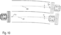
- This situation is in Fig. 10 shown.
- Figure 10 illustrates the above-described adaptation of the robot trajectory of a path segment 402 to the partial image that was printed when the previous path segment 401 was traversed.
- the robot trajectory of the first path segment 401 actually executed when the first partial image is printed begins at a starting point S 401 .
- the value d does not have to be constant. In the present example, the value d increases with increasing distance from the starting point S 401 .
- this deviation can be analyzed by means of a camera and image processing of the printed partial image, and the trajectories in the following path segment 402 can be corrected accordingly by the determined value d.
- This correction can take place once before the start of printing in the second path segment (to determine the starting point S 402 of the trajectory of the second path segment 402) and also be continuously adapted when passing through the second path segment 402 (based on accumulating measurements carried out using a camera and image processing).
- the print commands i.e. those positions at which the printing of a pixel is triggered
- the robot 100 can also be equipped with level sensors in the paint tank 110, 111 and 112 and the detergent tank 113. If the level in one of the containers falls below a predefined level, the controller 117 of the robot 100 can trigger at least one acoustic or visual alarm. As an alternative to this, the controller 117 can also autonomously guide the robot 100 back to the starting point 400 or to another predefined point. As a result, the colorants 10 and the cleaning agent 11 can be refilled in good time and an unplanned termination of a printing process can be prevented. Irregular transitions caused by this in the print motif 2 can thus be prevented and a web 611, 612 and 613 can each be printed seamlessly in one pass.
- images with side lengths of 20 to 150 m can be printed. These images can be divided into smaller sub-images with sides of 30 m each and then printed one after the other. On the basis of the described systems for localizing the robot 100, the robot 100 can "seamlessly" join the individual partial images.
Landscapes
- Engineering & Computer Science (AREA)
- Physics & Mathematics (AREA)
- Radar, Positioning & Navigation (AREA)
- Remote Sensing (AREA)
- Aviation & Aerospace Engineering (AREA)
- General Physics & Mathematics (AREA)
- Automation & Control Theory (AREA)
- Robotics (AREA)
- Optics & Photonics (AREA)
- Electromagnetism (AREA)
- Spray Control Apparatus (AREA)
- Manipulator (AREA)
Claims (15)
- Procédé comprenant :la réception, par un dispositif sans fil (110), d'un ou de plusieurs messages de commande de ressources radio comprenant des paramètres de configuration de rapports d'informations d'état de canal, CSI, semi-persistants à transmettre par l'intermédiaire d'un canal partagé de liaison montante physique, PUSCH, d'une première cellule dans un groupe d'avance temporelle ;la réception d'informations de commande de liaison descendante, DCI, indiquant l'activation d'une pluralité de ressources PUSCH du PUSCH de la première cellule pour les rapports CSI semi-persistants ; eten réponse à l'expiration d'un temporisateur d'alignement temporel du groupe d'avance temporelle, l'effacement de premières ressources PUSCH parmi la pluralité de ressources PUSCH, dans lequel les premières ressources PUSCH se produisent après l'expiration du temporisateur d'alignement temporel.
- Procédé selon la revendication 1, comprenant en outre la transmission d'un premier rapport CSI semi-persistant, parmi les rapports CSI semi-persistants, par l'intermédiaire de secondes ressources PUSCH parmi la pluralité de ressources PUSCH, dans lequel les secondes ressources PUSCH se produisent avant l'expiration du temporisateur d'alignement temporel.
- Procédé selon l'une quelconque des revendications 1 et 2, dans lequel les un ou plusieurs messages de commande de ressources radio comprennent en outre :des premiers paramètres de configuration d'une ou de plusieurs cellules regroupées dans le groupe d'avance temporelle ; etdes seconds paramètres de configuration du temporisateur d'alignement temporel pour le groupe d'avance temporelle.
- Procédé selon l'une quelconque des revendications 1 à 3, dans lequel la pluralité de ressources PUSCH de la première cellule sont déterminées sur la base :des DCI ; etdes paramètres de configuration des rapports CSI semi-persistants.
- Procédé selon l'une quelconque des revendications 1 à 4, dans lequel les un ou plusieurs messages de commande de ressources radio sont un ou plusieurs messages de commande de ressources radio comprenant les paramètres de configuration des rapports CSI semi-persistants.
- Procédé selon l'une quelconque des revendications 1 à 5, comprenant en outre :la réception de secondes DCI indiquant l'activation d'une seconde pluralité de ressources PUSCH, dans lequel la seconde pluralité de ressources PUSCH sont déterminées sur la base :des secondes DCI ; etdes paramètres de configuration des rapports CSI semi-persistants ; etla transmission d'un second rapport CSI semi-persistant, parmi les rapports CSI semi-persistants, par l'intermédiaire de ressources de la seconde pluralité de ressources PUSCH.
- Dispositif sans fil (110) comprenant un ou plusieurs processeurs et une mémoire stockant des instructions qui, lorsqu'elles sont exécutées par les un ou plusieurs processeurs, amènent le dispositif sans fil à exécuter le procédé selon l'une quelconque des revendications 1 à 6.
- Support lisible par ordinateur non transitoire comprenant des instructions qui, lorsqu'elles sont exécutées par un ou plusieurs processeurs, amènent le ou les processeurs à exécuter le procédé selon l'une quelconque des revendications 1 à 6.
- Procédé comprenant :la transmission, par une station de base (120), d'un ou de plusieurs messages de commande de ressources radio comprenant des paramètres de configuration de rapports d'informations d'état de canal, CSI, semi-persistants à transmettre par l'intermédiaire d'un canal partagé de liaison montante physique, PUSCH, d'une première cellule dans un groupe d'avance temporelle ;la transmission d'informations de commande de liaison descendante, DCI, indiquant l'activation d'une pluralité de ressources PUSCH de la première cellule pour les rapports CSI semi-persistants ; eten réponse à l'expiration d'un temporisateur d'alignement temporel du groupe d'avance temporelle, l'effacement de premières ressources PUSCH parmi la pluralité de ressources PUSCH, dans lequel les premières ressources PUSCH se produisent après l'expiration du temporisateur d'alignement temporel.
- Procédé selon la revendication 9, comprenant en outre la réception d'un premier rapport CSI semi-persistant, parmi les rapports CSI semi-persistants, par l'intermédiaire de secondes ressources PUSCH parmi la pluralité de ressources PUSCH, dans lequel les secondes ressources PUSCH se produisent avant l'expiration du temporisateur d'alignement temporel.
- Procédé selon l'une quelconque des revendications 9 et 10, dans lequel les un ou plusieurs messages de commande de ressources radio comprennent en outre :des premiers paramètres de configuration d'une ou de plusieurs cellules regroupées dans le groupe d'avance temporelle ; etdes seconds paramètres de configuration du temporisateur d'alignement temporel pour le groupe d'avance temporelle.
- Procédé selon l'une quelconque des revendications 9 à 11, dans lequel la pluralité de ressources PUSCH de la première cellule sont déterminées sur la base :des DCI ; etdes paramètres de configuration des rapports CSI semi-persistants.
- Procédé selon l'une quelconque des revendications 9 à 12, dans lequel les un ou plusieurs messages de commande de ressources radio sont un ou plusieurs messages de commande de ressources radio comprenant les paramètres de configuration des rapports CSI semi-persistants.
- Station de base (120) comprenant un ou plusieurs processeurs et une mémoire stockant des instructions qui, lorsqu'elles sont exécutées par les un ou plusieurs processeurs, amènent la station de base à exécuter le procédé selon l'une quelconque des revendications 9 à 13.
- Support lisible par ordinateur non transitoire comprenant des instructions qui, lorsqu'elles sont exécutées par un ou plusieurs processeurs, amènent les un ou plusieurs processeurs à exécuter le procédé selon l'une quelconque des revendications 9 à 13.
Applications Claiming Priority (2)
| Application Number | Priority Date | Filing Date | Title |
|---|---|---|---|
| DE102016123731.0A DE102016123731B4 (de) | 2016-12-07 | 2016-12-07 | Roboter zum Drucken von Bildern auf Bodenflächen |
| PCT/AT2017/060329 WO2018102846A1 (fr) | 2016-12-07 | 2017-12-07 | Dispositif pour imprimer des images sur des surfaces de sol |
Publications (2)
| Publication Number | Publication Date |
|---|---|
| EP3551345A1 EP3551345A1 (fr) | 2019-10-16 |
| EP3551345B1 true EP3551345B1 (fr) | 2021-01-20 |
Family
ID=60888054
Family Applications (1)
| Application Number | Title | Priority Date | Filing Date |
|---|---|---|---|
| EP17822540.5A Active EP3551345B1 (fr) | 2016-12-07 | 2017-12-07 | Dispositif pour l'impression d'une image sur la surface d'un sol |
Country Status (6)
| Country | Link |
|---|---|
| US (1) | US11090672B2 (fr) |
| EP (1) | EP3551345B1 (fr) |
| CN (1) | CN110325287A (fr) |
| AU (1) | AU2017371377A1 (fr) |
| DE (1) | DE102016123731B4 (fr) |
| WO (1) | WO2018102846A1 (fr) |
Families Citing this family (43)
| Publication number | Priority date | Publication date | Assignee | Title |
|---|---|---|---|---|
| DE102016014944A1 (de) | 2016-12-14 | 2018-06-14 | Dürr Systems Ag | Beschichtungsverfahren und entsprechende Beschichtungseinrichtung |
| DE102016014946A1 (de) | 2016-12-14 | 2018-06-14 | Dürr Systems Ag | Druckkopf zur Applikation eines Beschichtungsmittels auf ein Bauteil |
| DE102016014948A1 (de) | 2016-12-14 | 2018-06-14 | Dürr Systems Ag | Druckkopf und zugehöriges Betriebsverfahren |
| DE102016014920A1 (de) | 2016-12-14 | 2018-06-14 | Dürr Systems Ag | Druckkopf mit Verschiebe- und/oder Drehmechanik für zumindest eine Düsenreihe |
| DE102016014951A1 (de) | 2016-12-14 | 2018-06-14 | Dürr Systems Ag | Beschichtungseinrichtung und zugehöriges Betriebsverfahren |
| DE102016014952A1 (de) | 2016-12-14 | 2018-06-14 | Dürr Systems Ag | Beschichtungseinrichtung zur Beschichtung von Bauteilen |
| DE102016014947A1 (de) | 2016-12-14 | 2018-06-14 | Dürr Systems Ag | Druckkopf zur Applikation eines Beschichtungsmittels |
| DE102016014956A1 (de) | 2016-12-14 | 2018-06-14 | Dürr Systems Ag | Beschichtungseinrichtung und zugehöriges Betriebsverfahren |
| DE102016014955A1 (de) | 2016-12-14 | 2018-06-14 | Dürr Systems Ag | Beschichtungseinrichtung und entsprechendes Beschichtungsverfahren |
| DE102016014953A1 (de) | 2016-12-14 | 2018-06-14 | Dürr Systems Ag | Lackieranlage und entsprechendes Lackierverfahren |
| DE102016014919A1 (de) | 2016-12-14 | 2018-06-14 | Dürr Systems Ag | Applikationsvorrichtung und Verfahren zum Applizieren eines Beschichtungsmittels |
| DE102016014943A1 (de) | 2016-12-14 | 2018-06-14 | Dürr Systems Ag | Druckkopf mit Temperiereinrichtung |
| US12526374B1 (en) * | 2017-04-20 | 2026-01-13 | Newtonoid Technologies, L.L.C. | Mobile printer |
| US12539525B2 (en) | 2017-11-30 | 2026-02-03 | Axalta Coating Systems Ip Co., Llc | Coating compositions for application utilizing a high transfer efficiency applicator and methods and systems thereof |
| KR102634160B1 (ko) | 2017-11-30 | 2024-02-06 | 악살타 코팅 시스템즈 게엠베하 | 고 전달 효율 어플리케이터를 활용하는 코팅 조성물의 적용을 위한 시스템, 코팅 층 및 상응하는 방법 |
| US11872580B2 (en) * | 2018-01-30 | 2024-01-16 | Ford Motor Company | Composite ultrasonic material applicators with embedded shaping gas micro-applicators and methods of use thereof |
| US11222147B2 (en) * | 2018-02-21 | 2022-01-11 | Image Clone, Llc | System and method for automated layout of buildings |
| CN109261407B (zh) * | 2018-10-19 | 2021-07-16 | 飞码机器人私人有限公司 | 一种表面涂装机器人作业系统及方法 |
| US12296459B2 (en) * | 2018-11-21 | 2025-05-13 | Dusty Robotics, Inc. | Mobile printing robot and related methods |
| WO2021030480A1 (fr) | 2019-08-12 | 2021-02-18 | Dusty Robotics, Inc. | Système d'impression de robot mobile à précision de position améliorée |
| US11338576B2 (en) | 2019-09-13 | 2022-05-24 | Dusty Robotics, Inc. | Mobile robot printing with wind protection |
| JP7401277B2 (ja) * | 2019-12-04 | 2023-12-19 | ファナック株式会社 | ロボットプログラミング装置 |
| CN113431301B (zh) * | 2020-03-20 | 2022-04-12 | 广东博智林机器人有限公司 | 一种喷涂路径确定方法、装置、电子设备及存储介质 |
| US12122932B2 (en) | 2020-05-29 | 2024-10-22 | Axalta Coating Systems Ip Co., Llc | Coating compositions for application utilizing a high transfer efficiency applicator and methods and systems thereof |
| CN111907215A (zh) * | 2020-08-06 | 2020-11-10 | 王金星 | 基于移动物联网环保作业系统 |
| FR3115716B1 (fr) * | 2020-11-05 | 2023-12-22 | Exel Ind | Procede et installation d’application d’un produit de revetement sur une surface |
| JP7764177B2 (ja) * | 2021-09-24 | 2025-11-05 | 株式会社トプコン | 墨出し装置、墨出し装置の制御方法およびプログラム |
| DE102021133047A1 (de) | 2021-12-14 | 2023-06-15 | Homag Gmbh | Druckvorrichtung und Verfahren zum Bedrucken eines Werkstücks |
| GB202204971D0 (en) | 2022-04-05 | 2022-05-18 | Micropply Ltd | Ground marking robot, method of ground marking using a guide |
| GB2616895A (en) | 2022-03-24 | 2023-09-27 | Micropply Ltd | Autonomous deposition machine with improved deposition layout features |
| WO2023180761A2 (fr) | 2022-03-24 | 2023-09-28 | Micropply Limited | Système de navigation amélioré pour un robot mobile autonome (amr) |
| GB2617090A (en) * | 2022-03-29 | 2023-10-04 | Micropply Ltd | Improved ground deposition robot deposition accounting for overspray |
| WO2023187367A1 (fr) * | 2022-03-29 | 2023-10-05 | Micropply Limited | Disposition de cartographie de dépôt améliorée pour une machine de dépôt au sol autonome et procédé associé |
| GB202205018D0 (en) | 2022-04-06 | 2022-05-18 | Micropply Ltd | Autonomous ground deposition machine with multiple accessory means |
| US20250222482A1 (en) | 2022-04-06 | 2025-07-10 | Micropply Limited | Improved deposition arrangement for a ground deposition machine |
| US20250222341A1 (en) | 2022-04-06 | 2025-07-10 | Micropply Limited | A coupling arrangement for a detachable ground deposition accessory |
| EP4543186A1 (fr) | 2022-04-06 | 2025-04-30 | Micropply Limited | Accessoire de dépôt au sol détachable |
| US12521748B2 (en) | 2022-04-06 | 2026-01-13 | Micropply Limited | Ground deposition machine for sloping surfaces |
| CA3265362A1 (fr) * | 2022-08-19 | 2024-02-22 | Rugged Robotics Inc. | Plateforme de mobilité pour navigation autonome de chantiers |
| WO2024064685A1 (fr) * | 2022-09-19 | 2024-03-28 | Dusty Robotics, Inc. | Système et procédé de commande à deux étages de robot imprimeur de terrain |
| TWI815730B (zh) * | 2022-11-16 | 2023-09-11 | 樹德科技大學 | 道路繪圖裝置 |
| EP4698327A1 (fr) * | 2023-04-20 | 2026-02-25 | Sika Technology AG | Appareil de pulvérisation mobile autonome |
| CN117506898B (zh) * | 2023-11-06 | 2026-04-17 | 珠海格力电器股份有限公司 | 标记构建方法、装置、清洁机器人和存储介质 |
Family Cites Families (19)
| Publication number | Priority date | Publication date | Assignee | Title |
|---|---|---|---|---|
| GB2266863A (en) | 1992-05-15 | 1993-11-17 | Charles Francis Thompson | Selective marking of large areas such as landscapes. |
| US6330503B1 (en) * | 1999-02-22 | 2001-12-11 | Trimble Navigation Limited | Global positioning system controlled staking apparatus |
| FR2814395B1 (fr) * | 2000-09-26 | 2003-03-28 | Imaje Sa | Procede et dispositif de nettoyage de buses pour imprimantes a jet d'encre, et tete d'impression et imprimante integrant un tel dispositif |
| DE10202553A1 (de) | 2002-01-24 | 2003-08-07 | Burkhard Buestgens | Verfahren zum Auftragen von Farben oder Lacken |
| JP5195128B2 (ja) * | 2008-07-31 | 2013-05-08 | セイコーエプソン株式会社 | 記録装置及び記録装置の制御方法 |
| US20120325924A1 (en) * | 2009-11-04 | 2012-12-27 | American Roadprinting, Llc | Apparatus and method for applying a fluid to a surface |
| US20120291819A1 (en) * | 2010-02-12 | 2012-11-22 | Honda Motor Co., Ltd. | Cleaning apparatus and cleaning method for coating gun |
| CN102019252B (zh) * | 2010-06-01 | 2013-02-20 | 陈尚文 | 一种气能雾化喷涂设备 |
| EP2799150B1 (fr) * | 2013-05-02 | 2016-04-27 | Hexagon Technology Center GmbH | Système d'application graphique |
| EP2433716A1 (fr) * | 2010-09-22 | 2012-03-28 | Hexagon Technology Center GmbH | Dispositif d'éclaboussure de surfaces avec un mécanisme de régulation de buse et procédé correspondant |
| US20120186606A1 (en) * | 2011-01-20 | 2012-07-26 | Barss Steven H | Cleaning of Nozzle Plate |
| EP2641661B1 (fr) * | 2012-03-20 | 2016-05-11 | Hexagon Technology Center GmbH | Système d'application graphique |
| US9598826B2 (en) * | 2012-10-30 | 2017-03-21 | Capstan Ag Systems, Inc. | Paint spraying system |
| ES2537222A1 (es) | 2013-07-16 | 2015-06-03 | Joaquín Alcázar García | Máquina para el tratamiento de una lámina de cartón, papel o similares |
| GB2516426B (en) * | 2013-07-17 | 2015-10-07 | Gurulogic Microsystems Oy | Encoder, decoder and method of operation using interpolation |
| CN103657919A (zh) * | 2013-10-24 | 2014-03-26 | 江苏凯富铸业有限公司 | V法铸造用涂料喷涂机 |
| CN103611648B (zh) * | 2013-11-03 | 2016-02-03 | 大连华工创新科技股份有限公司 | 喷嘴自动清洗装置 |
| EP2985385A1 (fr) * | 2014-08-11 | 2016-02-17 | Xavier Blanch Andreu | Dispositif de pulvérisation permettant de pulvériser un produit liquide sur une feuille de papier |
| CN104607331B (zh) * | 2014-11-26 | 2017-01-25 | 兰考三强木业有限公司 | 全自动自冲洗喷漆系统 |
-
2016
- 2016-12-07 DE DE102016123731.0A patent/DE102016123731B4/de not_active Expired - Fee Related
-
2017
- 2017-12-07 WO PCT/AT2017/060329 patent/WO2018102846A1/fr not_active Ceased
- 2017-12-07 AU AU2017371377A patent/AU2017371377A1/en not_active Abandoned
- 2017-12-07 CN CN201780084373.3A patent/CN110325287A/zh active Pending
- 2017-12-07 EP EP17822540.5A patent/EP3551345B1/fr active Active
- 2017-12-07 US US16/466,937 patent/US11090672B2/en not_active Expired - Fee Related
Also Published As
| Publication number | Publication date |
|---|---|
| DE102016123731B4 (de) | 2019-03-21 |
| DE102016123731A1 (de) | 2018-06-07 |
| WO2018102846A1 (fr) | 2018-06-14 |
| AU2017371377A1 (en) | 2019-07-25 |
| US11090672B2 (en) | 2021-08-17 |
| US20190381529A1 (en) | 2019-12-19 |
| EP3551345A1 (fr) | 2019-10-16 |
| CN110325287A (zh) | 2019-10-11 |
Similar Documents
| Publication | Publication Date | Title |
|---|---|---|
| EP3551345B1 (fr) | Dispositif pour l'impression d'une image sur la surface d'un sol | |
| EP3482622B1 (fr) | Procédé de guidage automatique d'un véhicule le long d'un système de rails virtuel | |
| DE69805160T2 (de) | Fahrzeugkombination | |
| EP3676112B1 (fr) | Système d'identification d'une remorque et d'assistance d'un processus d'accouplement à un véhicule tracteur | |
| DE102016011324A1 (de) | Verfahren zur Steuerung eines Zugfahrzeugs bei dessen Heranfahren und Ankuppeln an ein Anhängerfahrzeug | |
| DE102020121899A1 (de) | System zum ausrichten einer standort-kennung einer fahrzeugkupplung mit einem anhängerkoppler | |
| EP3153940B1 (fr) | Dispositif et méthode pour contrôle un véhicule | |
| DE10202553A1 (de) | Verfahren zum Auftragen von Farben oder Lacken | |
| EP3333049A1 (fr) | Procédé de manoeuvre autonome d'un véhicule automobile sur un parking à partir d'un couloir de circulation en fonction d'une carte numérique, dispositif d'infrastructure, systèmes d'aide à la conduite, véhicules automobiles ainsi que systèmes de communication | |
| DE102018210340B4 (de) | Verfahren und System zum Ermitteln einer Relativpose zwischen einem Zielobjekt und einem Fahrzeug | |
| DE102021110287A1 (de) | Verfahren und System zum automatisierten Kalibrieren von Sensoren | |
| DE102019203394A1 (de) | Verfahren zum Einstellen eines Parameters einer landwirtschaftlichen Spritzvorrichtung | |
| DE102019116951A1 (de) | System zur Erfassung von und Reaktion auf einen zurückweichenden Anhänger | |
| EP4102330B1 (fr) | Procédé de déplacement d'un véhicule vers un composant d'un objet espacé de celui-ci (transformation de coordonnées) | |
| DE102014103787A1 (de) | Verfahren zum Ausbringen von Pflanzenschutzmittel | |
| DE10328395B4 (de) | Verfahren zur Steuerung einer Landmaschine | |
| DE102021204363A1 (de) | Verfahren zur Kalibrierung eines Sensors mittels eines Fortbewegungsmittels | |
| DE102018008792A1 (de) | Vorrichtung zum zeitgleichen Kalibrieren eines Mehrsensorsystems | |
| EP4344908A2 (fr) | Système d'alignement pour l'approche d'un véhicule à un objet cible espacé de l'espace à cet effet | |
| EP4102329B1 (fr) | Procédé de déplacement d'un véhicule vers un composant d'un objet espacé de celui-ci (point de positionnement préalable) | |
| EP2603403B1 (fr) | Methode d'affichage d'images sur un panneau d'affichage dans un véhicule automobile, système d'aide à la conduite et véhicule | |
| DE102015208913A1 (de) | Verfahren und Vorrichtung zum Betreiben eines Fahrzeugs | |
| DE102023126316A1 (de) | Automatische erkennung spiegelreflektierender strabenoberflächen unter verwendung polarimetrischer bilddaten | |
| DE102021110739A1 (de) | System und verfahren zur steuerung von gefesselten selbstfahrenden plattformen | |
| DE102016212426A1 (de) | Verfahren zur Bestimmung einer Position und/oder einer Orientierung eines Kraftfahrzeugs |
Legal Events
| Date | Code | Title | Description |
|---|---|---|---|
| STAA | Information on the status of an ep patent application or granted ep patent |
Free format text: STATUS: UNKNOWN |
|
| STAA | Information on the status of an ep patent application or granted ep patent |
Free format text: STATUS: THE INTERNATIONAL PUBLICATION HAS BEEN MADE |
|
| PUAI | Public reference made under article 153(3) epc to a published international application that has entered the european phase |
Free format text: ORIGINAL CODE: 0009012 |
|
| STAA | Information on the status of an ep patent application or granted ep patent |
Free format text: STATUS: REQUEST FOR EXAMINATION WAS MADE |
|
| 17P | Request for examination filed |
Effective date: 20190705 |
|
| AK | Designated contracting states |
Kind code of ref document: A1 Designated state(s): AL AT BE BG CH CY CZ DE DK EE ES FI FR GB GR HR HU IE IS IT LI LT LU LV MC MK MT NL NO PL PT RO RS SE SI SK SM TR |
|
| AX | Request for extension of the european patent |
Extension state: BA ME |
|
| DAV | Request for validation of the european patent (deleted) | ||
| DAX | Request for extension of the european patent (deleted) | ||
| GRAP | Despatch of communication of intention to grant a patent |
Free format text: ORIGINAL CODE: EPIDOSNIGR1 |
|
| STAA | Information on the status of an ep patent application or granted ep patent |
Free format text: STATUS: GRANT OF PATENT IS INTENDED |
|
| RIC1 | Information provided on ipc code assigned before grant |
Ipc: B41J 2/165 20060101ALI20200630BHEP Ipc: B41J 3/407 20060101ALI20200630BHEP Ipc: B05B 12/08 20060101ALI20200630BHEP Ipc: B05B 15/555 20180101ALI20200630BHEP Ipc: B41J 3/28 20060101ALI20200630BHEP Ipc: B05B 12/12 20060101ALI20200630BHEP Ipc: B05B 13/04 20060101ALI20200630BHEP Ipc: B05B 9/04 20060101ALN20200630BHEP Ipc: B05B 12/04 20060101AFI20200630BHEP Ipc: B05B 13/00 20060101ALI20200630BHEP Ipc: B05B 15/55 20180101ALI20200630BHEP |
|
| INTG | Intention to grant announced |
Effective date: 20200715 |
|
| GRAS | Grant fee paid |
Free format text: ORIGINAL CODE: EPIDOSNIGR3 |
|
| GRAA | (expected) grant |
Free format text: ORIGINAL CODE: 0009210 |
|
| STAA | Information on the status of an ep patent application or granted ep patent |
Free format text: STATUS: THE PATENT HAS BEEN GRANTED |
|
| AK | Designated contracting states |
Kind code of ref document: B1 Designated state(s): AL AT BE BG CH CY CZ DE DK EE ES FI FR GB GR HR HU IE IS IT LI LT LU LV MC MK MT NL NO PL PT RO RS SE SI SK SM TR |
|
| REG | Reference to a national code |
Ref country code: GB Ref legal event code: FG4D Free format text: NOT ENGLISH |
|
| REG | Reference to a national code |
Ref country code: CH Ref legal event code: EP |
|
| REG | Reference to a national code |
Ref country code: AT Ref legal event code: REF Ref document number: 1355915 Country of ref document: AT Kind code of ref document: T Effective date: 20210215 |
|
| REG | Reference to a national code |
Ref country code: IE Ref legal event code: FG4D Free format text: LANGUAGE OF EP DOCUMENT: GERMAN |
|
| REG | Reference to a national code |
Ref country code: DE Ref legal event code: R096 Ref document number: 502017009173 Country of ref document: DE |
|
| REG | Reference to a national code |
Ref country code: CH Ref legal event code: NV Representative=s name: PINTZ AND PARTNERS LLC, CH |
|
| REG | Reference to a national code |
Ref country code: NL Ref legal event code: FP |
|
| REG | Reference to a national code |
Ref country code: LT Ref legal event code: MG9D |
|
| PG25 | Lapsed in a contracting state [announced via postgrant information from national office to epo] |
Ref country code: GR Free format text: LAPSE BECAUSE OF FAILURE TO SUBMIT A TRANSLATION OF THE DESCRIPTION OR TO PAY THE FEE WITHIN THE PRESCRIBED TIME-LIMIT Effective date: 20210421 Ref country code: HR Free format text: LAPSE BECAUSE OF FAILURE TO SUBMIT A TRANSLATION OF THE DESCRIPTION OR TO PAY THE FEE WITHIN THE PRESCRIBED TIME-LIMIT Effective date: 20210120 Ref country code: FI Free format text: LAPSE BECAUSE OF FAILURE TO SUBMIT A TRANSLATION OF THE DESCRIPTION OR TO PAY THE FEE WITHIN THE PRESCRIBED TIME-LIMIT Effective date: 20210120 Ref country code: PT Free format text: LAPSE BECAUSE OF FAILURE TO SUBMIT A TRANSLATION OF THE DESCRIPTION OR TO PAY THE FEE WITHIN THE PRESCRIBED TIME-LIMIT Effective date: 20210520 Ref country code: NO Free format text: LAPSE BECAUSE OF FAILURE TO SUBMIT A TRANSLATION OF THE DESCRIPTION OR TO PAY THE FEE WITHIN THE PRESCRIBED TIME-LIMIT Effective date: 20210420 Ref country code: BG Free format text: LAPSE BECAUSE OF FAILURE TO SUBMIT A TRANSLATION OF THE DESCRIPTION OR TO PAY THE FEE WITHIN THE PRESCRIBED TIME-LIMIT Effective date: 20210420 Ref country code: LT Free format text: LAPSE BECAUSE OF FAILURE TO SUBMIT A TRANSLATION OF THE DESCRIPTION OR TO PAY THE FEE WITHIN THE PRESCRIBED TIME-LIMIT Effective date: 20210120 |
|
| PG25 | Lapsed in a contracting state [announced via postgrant information from national office to epo] |
Ref country code: RS Free format text: LAPSE BECAUSE OF FAILURE TO SUBMIT A TRANSLATION OF THE DESCRIPTION OR TO PAY THE FEE WITHIN THE PRESCRIBED TIME-LIMIT Effective date: 20210120 Ref country code: LV Free format text: LAPSE BECAUSE OF FAILURE TO SUBMIT A TRANSLATION OF THE DESCRIPTION OR TO PAY THE FEE WITHIN THE PRESCRIBED TIME-LIMIT Effective date: 20210120 Ref country code: PL Free format text: LAPSE BECAUSE OF FAILURE TO SUBMIT A TRANSLATION OF THE DESCRIPTION OR TO PAY THE FEE WITHIN THE PRESCRIBED TIME-LIMIT Effective date: 20210120 Ref country code: SE Free format text: LAPSE BECAUSE OF FAILURE TO SUBMIT A TRANSLATION OF THE DESCRIPTION OR TO PAY THE FEE WITHIN THE PRESCRIBED TIME-LIMIT Effective date: 20210120 |
|
| PG25 | Lapsed in a contracting state [announced via postgrant information from national office to epo] |
Ref country code: IS Free format text: LAPSE BECAUSE OF FAILURE TO SUBMIT A TRANSLATION OF THE DESCRIPTION OR TO PAY THE FEE WITHIN THE PRESCRIBED TIME-LIMIT Effective date: 20210520 |
|
| REG | Reference to a national code |
Ref country code: DE Ref legal event code: R097 Ref document number: 502017009173 Country of ref document: DE |
|
| PG25 | Lapsed in a contracting state [announced via postgrant information from national office to epo] |
Ref country code: EE Free format text: LAPSE BECAUSE OF FAILURE TO SUBMIT A TRANSLATION OF THE DESCRIPTION OR TO PAY THE FEE WITHIN THE PRESCRIBED TIME-LIMIT Effective date: 20210120 Ref country code: CZ Free format text: LAPSE BECAUSE OF FAILURE TO SUBMIT A TRANSLATION OF THE DESCRIPTION OR TO PAY THE FEE WITHIN THE PRESCRIBED TIME-LIMIT Effective date: 20210120 Ref country code: SM Free format text: LAPSE BECAUSE OF FAILURE TO SUBMIT A TRANSLATION OF THE DESCRIPTION OR TO PAY THE FEE WITHIN THE PRESCRIBED TIME-LIMIT Effective date: 20210120 |
|
| PLBE | No opposition filed within time limit |
Free format text: ORIGINAL CODE: 0009261 |
|
| STAA | Information on the status of an ep patent application or granted ep patent |
Free format text: STATUS: NO OPPOSITION FILED WITHIN TIME LIMIT |
|
| PG25 | Lapsed in a contracting state [announced via postgrant information from national office to epo] |
Ref country code: DK Free format text: LAPSE BECAUSE OF FAILURE TO SUBMIT A TRANSLATION OF THE DESCRIPTION OR TO PAY THE FEE WITHIN THE PRESCRIBED TIME-LIMIT Effective date: 20210120 Ref country code: SK Free format text: LAPSE BECAUSE OF FAILURE TO SUBMIT A TRANSLATION OF THE DESCRIPTION OR TO PAY THE FEE WITHIN THE PRESCRIBED TIME-LIMIT Effective date: 20210120 Ref country code: RO Free format text: LAPSE BECAUSE OF FAILURE TO SUBMIT A TRANSLATION OF THE DESCRIPTION OR TO PAY THE FEE WITHIN THE PRESCRIBED TIME-LIMIT Effective date: 20210120 |
|
| 26N | No opposition filed |
Effective date: 20211021 |
|
| PG25 | Lapsed in a contracting state [announced via postgrant information from national office to epo] |
Ref country code: AL Free format text: LAPSE BECAUSE OF FAILURE TO SUBMIT A TRANSLATION OF THE DESCRIPTION OR TO PAY THE FEE WITHIN THE PRESCRIBED TIME-LIMIT Effective date: 20210120 Ref country code: ES Free format text: LAPSE BECAUSE OF FAILURE TO SUBMIT A TRANSLATION OF THE DESCRIPTION OR TO PAY THE FEE WITHIN THE PRESCRIBED TIME-LIMIT Effective date: 20210120 |
|
| PG25 | Lapsed in a contracting state [announced via postgrant information from national office to epo] |
Ref country code: SI Free format text: LAPSE BECAUSE OF FAILURE TO SUBMIT A TRANSLATION OF THE DESCRIPTION OR TO PAY THE FEE WITHIN THE PRESCRIBED TIME-LIMIT Effective date: 20210120 |
|
| PG25 | Lapsed in a contracting state [announced via postgrant information from national office to epo] |
Ref country code: IT Free format text: LAPSE BECAUSE OF FAILURE TO SUBMIT A TRANSLATION OF THE DESCRIPTION OR TO PAY THE FEE WITHIN THE PRESCRIBED TIME-LIMIT Effective date: 20210120 |
|
| PG25 | Lapsed in a contracting state [announced via postgrant information from national office to epo] |
Ref country code: IS Free format text: LAPSE BECAUSE OF FAILURE TO SUBMIT A TRANSLATION OF THE DESCRIPTION OR TO PAY THE FEE WITHIN THE PRESCRIBED TIME-LIMIT Effective date: 20210520 |
|
| PG25 | Lapsed in a contracting state [announced via postgrant information from national office to epo] |
Ref country code: MC Free format text: LAPSE BECAUSE OF FAILURE TO SUBMIT A TRANSLATION OF THE DESCRIPTION OR TO PAY THE FEE WITHIN THE PRESCRIBED TIME-LIMIT Effective date: 20210120 |
|
| PG25 | Lapsed in a contracting state [announced via postgrant information from national office to epo] |
Ref country code: LU Free format text: LAPSE BECAUSE OF NON-PAYMENT OF DUE FEES Effective date: 20211207 Ref country code: IE Free format text: LAPSE BECAUSE OF NON-PAYMENT OF DUE FEES Effective date: 20211207 |
|
| PG25 | Lapsed in a contracting state [announced via postgrant information from national office to epo] |
Ref country code: CY Free format text: LAPSE BECAUSE OF FAILURE TO SUBMIT A TRANSLATION OF THE DESCRIPTION OR TO PAY THE FEE WITHIN THE PRESCRIBED TIME-LIMIT Effective date: 20210120 |
|
| PG25 | Lapsed in a contracting state [announced via postgrant information from national office to epo] |
Ref country code: HU Free format text: LAPSE BECAUSE OF FAILURE TO SUBMIT A TRANSLATION OF THE DESCRIPTION OR TO PAY THE FEE WITHIN THE PRESCRIBED TIME-LIMIT; INVALID AB INITIO Effective date: 20171207 |
|
| PG25 | Lapsed in a contracting state [announced via postgrant information from national office to epo] |
Ref country code: MK Free format text: LAPSE BECAUSE OF FAILURE TO SUBMIT A TRANSLATION OF THE DESCRIPTION OR TO PAY THE FEE WITHIN THE PRESCRIBED TIME-LIMIT Effective date: 20210120 |
|
| PGFP | Annual fee paid to national office [announced via postgrant information from national office to epo] |
Ref country code: DE Payment date: 20240126 Year of fee payment: 7 |
|
| PG25 | Lapsed in a contracting state [announced via postgrant information from national office to epo] |
Ref country code: MT Free format text: LAPSE BECAUSE OF FAILURE TO SUBMIT A TRANSLATION OF THE DESCRIPTION OR TO PAY THE FEE WITHIN THE PRESCRIBED TIME-LIMIT Effective date: 20210120 |
|
| PGFP | Annual fee paid to national office [announced via postgrant information from national office to epo] |
Ref country code: BE Payment date: 20241216 Year of fee payment: 8 Ref country code: NL Payment date: 20241217 Year of fee payment: 8 |
|
| PGFP | Annual fee paid to national office [announced via postgrant information from national office to epo] |
Ref country code: GB Payment date: 20241218 Year of fee payment: 8 |
|
| PGFP | Annual fee paid to national office [announced via postgrant information from national office to epo] |
Ref country code: FR Payment date: 20241217 Year of fee payment: 8 |
|
| PGFP | Annual fee paid to national office [announced via postgrant information from national office to epo] |
Ref country code: AT Payment date: 20241213 Year of fee payment: 8 |
|
| PGFP | Annual fee paid to national office [announced via postgrant information from national office to epo] |
Ref country code: CH Payment date: 20250101 Year of fee payment: 8 |
|
| REG | Reference to a national code |
Ref country code: DE Ref legal event code: R119 Ref document number: 502017009173 Country of ref document: DE |
|
| PG25 | Lapsed in a contracting state [announced via postgrant information from national office to epo] |
Ref country code: DE Free format text: LAPSE BECAUSE OF NON-PAYMENT OF DUE FEES Effective date: 20250701 |
|
| PG25 | Lapsed in a contracting state [announced via postgrant information from national office to epo] |
Ref country code: TR Free format text: LAPSE BECAUSE OF FAILURE TO SUBMIT A TRANSLATION OF THE DESCRIPTION OR TO PAY THE FEE WITHIN THE PRESCRIBED TIME-LIMIT Effective date: 20210120 |
|
| REG | Reference to a national code |
Ref country code: CH Ref legal event code: R18 Free format text: ST27 STATUS EVENT CODE: U-0-0-R10-R18 (AS PROVIDED BY THE NATIONAL OFFICE) Effective date: 20260331 |