EP3551408B1 - Buse mélangeuse pour dispositif d'application de béton projeté, ainsi que dispositif d'application de béton projeté comprenant une buse mélangeuse de ce type et procédé d'application de béton projeté - Google Patents
Buse mélangeuse pour dispositif d'application de béton projeté, ainsi que dispositif d'application de béton projeté comprenant une buse mélangeuse de ce type et procédé d'application de béton projeté Download PDFInfo
- Publication number
- EP3551408B1 EP3551408B1 EP17811934.3A EP17811934A EP3551408B1 EP 3551408 B1 EP3551408 B1 EP 3551408B1 EP 17811934 A EP17811934 A EP 17811934A EP 3551408 B1 EP3551408 B1 EP 3551408B1
- Authority
- EP
- European Patent Office
- Prior art keywords
- nozzle
- dry
- injection
- aerosol
- chamber
- Prior art date
- Legal status (The legal status is an assumption and is not a legal conclusion. Google has not performed a legal analysis and makes no representation as to the accuracy of the status listed.)
- Active
Links
Images


Classifications
-
- B—PERFORMING OPERATIONS; TRANSPORTING
- B05—SPRAYING OR ATOMISING IN GENERAL; APPLYING FLUENT MATERIALS TO SURFACES, IN GENERAL
- B05B—SPRAYING APPARATUS; ATOMISING APPARATUS; NOZZLES
- B05B7/00—Spraying apparatus for discharge of liquids or other fluent materials from two or more sources, e.g. of liquid and air, of powder and gas
- B05B7/14—Spraying apparatus for discharge of liquids or other fluent materials from two or more sources, e.g. of liquid and air, of powder and gas designed for spraying particulate materials
- B05B7/1404—Arrangements for supplying particulate material
- B05B7/1431—Arrangements for supplying particulate material comprising means for supplying an additional liquid
-
- B—PERFORMING OPERATIONS; TRANSPORTING
- B01—PHYSICAL OR CHEMICAL PROCESSES OR APPARATUS IN GENERAL
- B01F—MIXING, e.g. DISSOLVING, EMULSIFYING OR DISPERSING
- B01F25/00—Flow mixers; Mixers for falling materials, e.g. solid particles
- B01F25/30—Injector mixers
- B01F25/31—Injector mixers in conduits or tubes through which the main component flows
- B01F25/313—Injector mixers in conduits or tubes through which the main component flows wherein additional components are introduced in the centre of the conduit
-
- B—PERFORMING OPERATIONS; TRANSPORTING
- B05—SPRAYING OR ATOMISING IN GENERAL; APPLYING FLUENT MATERIALS TO SURFACES, IN GENERAL
- B05B—SPRAYING APPARATUS; ATOMISING APPARATUS; NOZZLES
- B05B7/00—Spraying apparatus for discharge of liquids or other fluent materials from two or more sources, e.g. of liquid and air, of powder and gas
- B05B7/14—Spraying apparatus for discharge of liquids or other fluent materials from two or more sources, e.g. of liquid and air, of powder and gas designed for spraying particulate materials
- B05B7/1481—Spray pistols or apparatus for discharging particulate material
- B05B7/149—Spray pistols or apparatus for discharging particulate material with separate inlets for a particulate material and a liquid to be sprayed
-
- B—PERFORMING OPERATIONS; TRANSPORTING
- B28—WORKING CEMENT, CLAY, OR STONE
- B28C—PREPARING CLAY; PRODUCING MIXTURES CONTAINING CLAY OR CEMENTITIOUS MATERIAL, e.g. PLASTER
- B28C5/00—Apparatus or methods for producing mixtures of cement with other substances, e.g. slurries, mortars, porous or fibrous compositions
- B28C5/02—Apparatus or methods for producing mixtures of cement with other substances, e.g. slurries, mortars, porous or fibrous compositions without using driven mechanical means effecting the mixing
- B28C5/026—Mixing guns or nozzles; Injector mixers
-
- E—FIXED CONSTRUCTIONS
- E04—BUILDING
- E04G—SCAFFOLDING; FORMS; SHUTTERING; BUILDING IMPLEMENTS OR AIDS, OR THEIR USE; HANDLING BUILDING MATERIALS ON THE SITE; REPAIRING, BREAKING-UP OR OTHER WORK ON EXISTING BUILDINGS
- E04G21/00—Preparing, conveying, or working-up building materials or building elements in situ; Other devices or measures for constructional work
- E04G21/02—Conveying or working-up concrete or similar masses able to be heaped or cast
- E04G21/04—Devices for both conveying and distributing
Definitions
- the present invention relates to a mixing nozzle or injection nozzle for a shotcrete application device for dry spraying of concrete, in particular refractory concrete, and such a shotcrete application device and a shotcrete application method or dry spraying method, in particular for applying refractory concrete.
- Shotcrete is conveyed to the installation site in a pipe or hose line, where it is applied pneumatically from a spray nozzle and compacted by the impact energy.
- the dry, preferably hydraulic, binder, the aggregates and additives as well as the additives are premixed dry and conveyed in a stream of compressed air through the pipe or hose line to a spray nozzle.
- Water or a liquid binder is added to the dry mixture in the spray nozzle and a spraying compound is produced. The gunning compound is then sprayed onto the surface to be coated in a continuous stream.
- the GB 2 025 794 A discloses a spray nozzle for applying shotcrete to building walls, among other things.
- the spray nozzle has an inlet end and an outlet end. A powdered cement mix is fed in at the inlet end.
- the spray nozzle has a mixing chamber in which the powdered cement mixture is mixed with water.
- a cylindrical sleeve is provided for this purpose, which surrounds the mixing chamber.
- the sleeve also has a number of radial bores through which the water enters the mixing chamber in the form of individual water jets. The gunning compound emerges at the tapering outlet end of the spray nozzle.
- Refractory concrete is made with a binder that hardens at room temperature and refractory aggregates.
- the binder which hardens at room temperature, causes the primary or cold bonding.
- Characteristic of refractory concrete is the transition from the primary or cold bond to the vitrified bond, which occurs when it is heated for the first time.
- Refractory concrete within the meaning of the invention has a pressure softening point T 05 according to DIN EN ISO 1893: 2009-09 of T 05 ⁇ 600° C., preferably T 05 ⁇ 800° C. Accordingly, fireproof or refractory aggregates within the meaning of the invention are aggregates that are suitable for a refractory concrete with the above-mentioned pressure softening point T 05 .
- the spray nozzle has a duct for feeding the fibers and a duct for feeding a dry mixture of binder and aggregate, the ducts being arranged so that the dry mixture is introduced tangentially into the stream of fibres.
- water is introduced radially outwardly from a ring having radial openings into the stream of dry blend and fiber material.
- the WO 2005/098333 A1 discloses a dry spraying method in which a premix of a first liquid and a dry mix is produced in a mixing device and this premix is mixed at a spray nozzle with a second liquid to form a fresh sprayed concrete mass.
- the first liquid can have a setting accelerator, for example. After the premix starts according to the WO 2005/098333 A1 already the binding process.
- the mixing device the first liquid is fed radially or slightly obliquely from the outside to the material flow of the dry mixture.
- the water is also supplied radially from the outside by means of a water ring.
- From the EP 1 153 861 A1 disclose a shotcrete application apparatus and method.
- a fine-grained, dry gunning compound which already contains hardener, is mixed with water in a mixing tube of a moistening device.
- the water is previously in the humidifier atomized with compressed air.
- Post-wetting can take place at the end of the mixing tube.
- the hardener can be added during the subsequent moistening.
- a spray nozzle for applying the gunning compound is arranged at the end of the mixing tube.
- From the WO 2010/105049 A2 describes a dry spraying process for refractory concrete in which a dry mix containing refractory material and a setting regulator is provided in a storage container.
- the dry mix is introduced into the air flow of a shotcrete applicator. Furthermore, a liquid binder is mixed with the dry mixture at or just before the spray nozzle of the sprayed concrete application device. The resulting fresh shotcrete mass is then applied to the surface to be coated using the spray nozzle.
- the EP 0 738 676 A1 discloses an apparatus for adding air, liquids or powdered solids to shotcrete lines.
- the device has an annular insert that can be inserted into the delivery line, with an inlet channel opening into an annular chamber of the insert and a plurality of outlet channels directed from the annular chamber to the delivery flow.
- the outlet channels are aligned at an angle to the conveying direction.
- a powdery mixture is introduced into a flow through the insert part.
- the flow can be an air/water mixture.
- a dry spraying method for spraying a gunning compound onto a surface with the following method steps: a) mixing a liquid injection material with conveying air to form an aerosol, b) Injecting the aerosol into the interior of a dry material stream consisting of a dry mixture and mixing the aerosol with the dry mixture to form a material mixture, c) conveying the material mixture by means of a hose line to a spray nozzle, e) applying the gunning compound to the surface to be coated using the spray nozzle.
- the US 4,844,340A discloses a mixing nozzle for spraying concrete in which dry material is mixed with a mixture of fibers and air to form a dry premix. Water is then added to the premix using a ring. The wet mixture then emerges from a nozzle.
- the US 2,543,517A discloses a mixing device in which an aqueous mixture of water and air is introduced into a dry material stream of dry mixture.
- the object of the present invention is to provide a sprayed concrete application device for dry spraying of concrete, in particular refractory concrete, and a sprayed concrete application method, with the physical properties of the applied sprayed concrete being able to be adapted and optimized easily and quickly.
- the shotcrete application device 1 has a compressed air source 2, three air delivery lines 3a; 3b; 3c connected to it, an injection material reservoir 4 filled with an injection medium or material, in particular an injection liquid, an injection material delivery line 5 connected thereto, preferably an injection material delivery pump 50, as well as a dry mixture reservoir 6 filled with a dry mixture or granular dry material and the mixing nozzle 8 according to the invention.
- an injection material flow meter 51 is also preferably provided, which is arranged within the injection material delivery line 5 .
- a first air conveying line 3a, the injection material conveying line 5 and the dry mixture reservoir 6 are each connected to the mixing nozzle 8 and feed the mixing nozzle 8 with the respective material or conveying air.
- a second air conveying line 3b is connected to the lower end of the dry mixture storage tank 6 and supplies conveying air to the dry mixture storage tank 6 for blowing out the dry mixture from the dry mixture storage tank 6 .
- a discharge device e.g. a rotor or a pocket wheel (not shown) at the lower end of the dry mixture storage container 6, which conveys the dry mixture from the dry mixture storage container 6 into a blow-out nozzle (not shown).
- the mixing nozzle 8 is connected directly or indirectly via an intermediate piece, e.g.
- the mixing nozzle 8 serves to mix the individual components of the sprayed concrete to be applied, i.e. the injection material from the injection material reservoir 4 with the dry mixture from the dry mixture reservoir 6 to form a particularly pre-wetted material mixture.
- the sprayed concrete application device 1 has a hose line 9 connected to the mixing nozzle 8, a spray nozzle 10, a liquid, preferably water or a liquid binder, filled liquid reservoir 11 and a liquid feed line 12 connected thereto and preferably a first and a second liquid feed pump 52; 53.
- the shotcrete application device 1 also preferably has a liquid flow meter 54 which is arranged within the liquid delivery line 12 .
- the first liquid feed pump 52 which sucks the liquid out of the liquid reservoir 11, is preferably a submersible pump.
- the second liquid feed pump 53 is preferably a high-pressure pump.
- the second liquid feed pump 53 feeds the liquid at a pressure of approx. 5 to 30 bar to a liquid injection device, for example a water ring, of the spray nozzle.
- the hose line 9 and the liquid delivery line 12 are both connected to the spray nozzle 10 and feed it the material mixture or the liquid that comes out of the mixing nozzle 8 and is in particular pre-wetted.
- the hose line 9 preferably has a length of at least 10 m.
- the spray nozzle 10 is thus used in a manner known per se to mix the, in particular pre-wetted, material mixture with the liquid to form a fresh sprayed concrete mix or sprayed mix, in particular a refractory sprayed concrete mix, and to spray the sprayed mix, in particular the refractory concrete sprayed mix, onto the respective substrate.
- the injection material is preferably an injection liquid.
- the injection material can also be a pourable or loose dry material, in particular a dry mixture.
- the injection material preferably contains at least one concrete additive or concrete admixture.
- Concrete additives or concrete admixtures are known to be added to the concrete in order to improve the properties of the fresh or hardened concrete, such as e.g. B. workability, solidification, hardening or frost resistance to change.
- Setting additives or setting additives or setting regulators affect the Setting reaction, eg the solidification and/or hardening reaction, of the respective binder.
- Concrete admixtures (in contrast to concrete additives) are added in such small quantities (total, i.e. the sum of all concrete admixtures ⁇ 5% by weight based on the dry mass of the total sum of aggregates and binders in the concrete) that they are irrelevant as a proportion of the concrete volume .
- Concrete additives or concrete admixtures can also serve as an aid in the ceramic firing, which in the case of refractory concrete takes place in situ after the application of the refractory concrete. Sintering aids, for example, lower the firing temperature. Additives or concrete admixtures are usually supplied in liquid, powder or granulate form.
- the injection material preferably contains at least one setting accelerator and/or hardening accelerator and/or retarder and/or plasticizer and/or a dust-binding agent and/or a gelling agent.
- Gelling agents are known to induce gelation of the binder.
- the setting accelerator serves in a manner known per se to stimulate the setting reaction of the binder and thereby increases the early strength.
- the solidification accelerator is preferably water glass or alkali solutions.
- dry injection material can contain cement and/or dry phosphates as accelerators.
- the injection material is liquid, it is in particular a suspension and/or solution and/or emulsion.
- the liquid injection material preferably contains at least water.
- the liquid injection material can also (additionally) contain oil and/or alcohol and/or glycerin.
- the injection material is a dry material or mixture, it is a powdered material or mixture with a grain size of ⁇ 0.5 mm, preferably ⁇ 0.1 mm, in accordance with DIN EN ISO 1927-3 (March 2013).
- the liquid or dry injection material can also contain other, in particular powdered, components.
- the injection material can contain microsilica or pyrogenic silicic acid or Aerosil or MgO, which act as sintering aids in the ceramic, in-situ firing of the refractory concrete.
- the sintering aids contribute little or nothing to the cold bonding, so they do not affect the setting reaction of the shotcrete, or only do so to a small extent.
- the injection liquid can also be pure water.
- the pourable or loose dry mixture consists of granular and possibly fibrous material.
- the dry mixture can consist exclusively of material which is essentially inert, ie does not react or reacts only insignificantly with the respective binder supplied at the spray nozzle 10 . In particular, no setting additives or setting additives are therefore contained in the dry mixture.
- the dry mixture preferably consists exclusively of mineral and refractory or refractory material or aggregate.
- refractory or refractory materials or aggregates within the meaning of the invention are materials or aggregates that are suitable for a refractory concrete with the above-mentioned pressure softening point T 05 .
- the dry mixture can also additionally contain at least one binder, in particular a binder in powder form. It is preferably a mineral binder.
- the dry mixture has clay and/or alumina cement and/or Portland cement and/or powdered water glass preparations and/or powdered phosphate preparations, in particular alumetaphosphate and/or monoaluminum phosphate, and/or dry resins and/or silicate binders as binders.
- the dry mixture preferably has both coarse and medium-grained and fine-grained components or coarse and medium-grain fractions (> 0.063 mm according to DIN EN ISO 1927-3 (March 2013)) and flour grain fractions ( ⁇ 0.063 mm according to DIN EN ISO 1927-3). (March 2013)) on.
- the dry mixture preferably has the following particle size distribution in accordance with DIN EN ISO 1927-3 (March 2013) (the proportions relate to the total dry matter and add up to 100% by weight): Sieve min [wt%] Max [wt%] > 6.3mm 0.0 10.0 > 3.15 - 6.3mm 0.0 20.0 > 1.00 - 3.15mm 15.0 40.0 > 0.063 - 1.00mm 15.0 40.0 ⁇ 0.063mm 20 55.0
- the liquid that is added at the tip nozzle 10 is pure water or liquid binder or a liquid containing concrete additives.
- the liquid binder is preferably a solution or suspension in water or another solvent, or a liquid polymer, preferably a synthetic resin.
- the suspension preferably contains dispersed colloidal particles.
- the liquid binder is preferably cement-free and solidifies and hardens directly after spraying as a result of the reaction with the additives contained in the injection material. In the case of refractory concrete, the liquid binder thus ensures the primary, so-called cold binding.
- the liquid binder is preferably a refractory or fireproof liquid binder which, after hardening, is therefore suitable for use in a refractory concrete with the above-mentioned pressure softening point.
- the liquid binder is preferably silica sol or water glass, preferably sodium and/or potassium and/or lithium water glass, or phosphoric acid or monoaluminum phosphate or a polymer binder, preferably synthetic resin, preferably phenolic resin, in particular novolak, or mixtures of the aforementioned binders .
- the liquid binder preferably contains no concrete additives or concrete admixtures. However, it can contain an antifreeze, for example, which prevents the liquid binder from freezing at low temperatures before mixing.
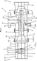
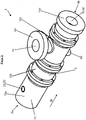
- the mixing nozzle 8 according to the invention ( 1 , 2 ) has an aerosol generating device 55 for generating an aerosol from the liquid or dry, free-flowing injection material and conveying air, and an aerosol injection device 56 for injecting the aerosol, in particular centrally, into the interior of a dry material stream consisting of a dry mixture.
- An aerosol is a heterogeneous mixture of solid and/or liquid airborne particles in a gas.
- the mixing nozzle 8 also has a nozzle housing 13 and a nozzle longitudinal axis 14 . Furthermore, the mixing nozzle 8 has a nozzle inlet end 8a and a nozzle outlet end 8b opposite this in the direction of the nozzle longitudinal axis 14 . In addition, the mixing nozzle 8 has a direction the nozzle longitudinal axis 14 through the mixing nozzle 8 through extending flow or conveying channel 15. The conveying channel 15 extends through the mixing nozzle 8 from the nozzle inlet end 8a to the nozzle outlet end 8b.
- a main conveying direction 18 of the mixing nozzle 8 is parallel to the nozzle longitudinal axis 14 and extends from the nozzle inlet end 8a to the nozzle outlet end 8b.
- the nozzle housing 13 also has a housing peripheral or outer wall 16 which surrounds the flow or delivery channel 15 .
- the housing wall 16 is preferably made of metal or ceramic or plastic.
- the mixing nozzle 8 also consists of several, in particular four, housing parts 13a to 13d, which are firmly connected to one another, in particular screwed. It is also within the scope of the invention that the housing part 13b is omitted and the housing parts 13a and 13c are placed directly next to one another, which will be discussed in more detail below.
- the dividing wall 19 has a plurality of, in particular circular-cylindrical, air passage channels 21 which extend through the dividing wall 19 in the main conveying direction 18 .
- the air passage channels 21 are distributed around the longitudinal nozzle axis 14 and are spaced apart from the longitudinal nozzle axis 14 , viewed in the circumferential direction in relation to the longitudinal nozzle axis 14 .
- the air passage channels 21 are preferably all at the same distance from the longitudinal axis 14 of the nozzle. There are preferably 5 to 20 air passage channels 21 .
- the air passage channels 21 are preferably also all equally spaced apart from one another in the circumferential direction.
- the second feed channel section 24 also has a channel axis which, however, extends parallel to the longitudinal nozzle axis 14 or main conveying direction 18.
- the channel axis is coaxial with the longitudinal axis 14 of the nozzle.
- the injection material feed channel 22 has a kink at which the first and the second feed channel section 23; 24 merge into one another.
- the second feed channel section 24 also opens into the aerosol chamber 20 .
- an atomizing or nebulizing nozzle 25 (shown schematically) is arranged in the second feed channel section 24 .
- the atomizing nozzle 25 is used for atomizing injection of the injection material into the aerosol chamber 20.
- the atomizing nozzle 25 is in particular a flat jet nozzle, smooth jet nozzle, hollow cone nozzle, full cone nozzle or mist nozzle (in the case of injection liquid) or a sandblasting nozzle or jet nozzle for free-flowing bulk materials (in the case of dry injection material).
- the first feed channel section 23 opens out to the surroundings.
- the first supply channel section 23 has means for connecting the injection material delivery line 5, in particular an internal thread 26.
- the aerosol chamber 20 has a peripheral chamber wall 27 surrounding the aerosol chamber 20 . Seen in the main conveying direction 18, the chamber peripheral wall 27 initially has a circular-cylindrical wall section 27a, which is followed by a further circular-cylindrical wall section 27b, the diameter of which, however, is larger than the diameter of the first wall section 27a.
- the second circular-cylindrical wall section 27b is followed by a conical wall section 27c which tapers as seen in the main conveying direction 18, ie as seen from the nozzle inlet end 8a to the nozzle outlet end 8b.
- the aerosol chamber 20 has a central chamber axis 28 which is preferably coaxial to the longitudinal axis 14 of the nozzle.
- the second cylindrical wall section 27b serves in particular to save material and can also be omitted, so that the first cylindrical wall section 27a merges directly into the conical wall section 27c. Or, if the housing part 13b is omitted, the conical wall section 27c is omitted.
- the chamber peripheral wall 27 is of continuous cylindrical design.
- the aerosol chamber 20 is adjoined by a connecting channel 29 , in particular a circular-cylindrical one.
- a channel axis of the connecting channel 29 is also preferably coaxial to the longitudinal axis of the nozzle 14.
- the connecting channel 29 opens into a second mixing chamber or vortex chamber 30.
- the connecting channel 29 also has an internal thread 31, which is used for screwing in an injection tube 32.
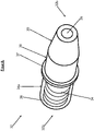
- the injection tube 32 ( 2 , 8th and 9 ) has an inlet-side tube end 32a and an outlet-side tube end 32b.
- the injection tube 32 is preferably made of metal or ceramic.
- the injection tube 32 has a tube longitudinal axis 33 which is preferably also coaxial to the nozzle longitudinal axis 14 .
- a tube wall 34 of the injection tube 32 has a tube wall outer surface 34a and a tube wall inner surface 34b.
- the inner surface 34b of the tube wall is of continuous circular-cylindrical design and surrounds a tube flow channel or tube conveying channel 35, which extends through the injection tube 32 from the tube end 32a on the inlet side to the tube end 32b on the outlet side.
- the vortex chamber 30 has a peripheral chamber wall 40 and a central chamber axis 41 which is coaxial with the longitudinal axis 14 of the nozzle.
- the chamber peripheral wall 40 of the vortex chamber 30 has, seen in the main conveying direction 18, a cylindrical wall section 40a and a conical wall section 40b adjoining it.
- the conical wall section 40b tapers as seen in the main conveying direction 18, ie as seen from the nozzle inlet end 8a to the nozzle outlet end 8b.
- the vortex chamber 30 opens into an outlet channel 42 with a preferably circular-cylindrical cross-section.
- the outlet channel 42 opens into the environment.
- One Channel axis of the outlet channel 42 is preferably coaxial to the nozzle longitudinal axis 14.
- the external thread 36 of the injection tube 32 is screwed into the internal thread 31 of the connecting channel 29 to such an extent that part of the injection tube 32 protrudes into the vortex chamber 30 .
- the area of the injection tube 32 protrudes with the circular-cylindrical and the conical surface section 38; 39 into the vortex chamber 30.
- a part of the injection tube 32 that has the outlet-side tube end 32b of the injection tube 32 projects into the vortex chamber 30 .
- the injection tube 32 is spaced apart from the chamber peripheral wall 40 so that a flow cross section is formed between them.
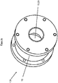
- the nozzle housing 13 also has a connecting piece 43 which is used to connect the dry mixture storage container 6 .
- the connecting piece 43 protrudes radially outwards from the peripheral wall 16 of the housing.
- the connecting piece 43 has a preferably cylindrical dry mixture inlet channel 44 .
- a channel axis 44a of the dry mixture inlet channel 44 extends radially to the longitudinal axis 14 of the nozzle.
- the channel axis 44a can also be arranged obliquely to the longitudinal axis 14 of the nozzle.
- the angle ⁇ is preferably ( 1 ) 30 to 90°. In particular, it is 90°.
- the dry mixture inlet channel 44 can, of course, also have a bent or kinked course. The angular ranges specified above then apply to the opening area in which the dry-mixture inlet channel 44 opens into the swirl chamber 30 .
- the dry-mixture inlet channel 44 extends through the housing peripheral wall 16 and opens into the swirl chamber 30.
- the dry-mixture inlet channel 44 is arranged in such a way that it is aligned in the radial direction in relation to the nozzle longitudinal axis 14 with the one that projects into the swirl chamber 30 Injection tube 32 is arranged.
- the dry mixture inlet channel 44 is preferably aligned in the radial direction with the circular-cylindrical one Surface section 38 of the injection tube 32 is arranged.
- the dry-mixture inlet channel 44 is thus arranged at the inlet-side end of the swirl chamber 30 .
- the dry mixture inlet channel 44 is arranged at the rear end of the swirl chamber 30 in the main conveying direction 18 .
- the dry mixture inlet channel 44 is arranged in the area of the cylindrical wall section 40a of the swirl chamber 30 .
- the mixing nozzle 8 according to the invention also preferably has an additional bypass air inlet channel 45 for the possible additional supply of bypass air.
- the air inlet duct 45 has a first inlet duct section 46 opening out into the environment and a second inlet duct section 47 adjoining it.
- the first inlet channel section 46 extends, in particular perpendicularly to the longitudinal axis 14 of the nozzle, through a further connecting piece 48 and into the housing wall 16 .
- a channel axis of the first inlet channel section 46 thus extends radially in relation to the nozzle longitudinal axis 14.
- the second inlet channel section 47 has a channel axis which extends parallel to the nozzle longitudinal axis 14.
- the entire compressed air supply of the shotcrete application device 1 is set up in such a way that the mixing nozzle 8 is operated at the same pressure level as the rest of the spraying machine 7. Because if the pressure in the mixing nozzle 8 is too high, the air would flow back into the machine 7. Conversely, the material mixture would be pressed into the injection tube 32 and the mixing nozzle 8 would be closed.
- conveying air is conveyed from the compressed air source 2 through the first air conveying line 3a into the air chamber 17 of the mixing nozzle 8.
- the conveying air flows from the air chamber 17 through the air passage channels 21 in the main conveying direction 18 into the aerosol chamber 20.
- the injection material is conveyed from the injection material reservoir 4, for example by means of the injection material feed pump 50, which is preferably a compressed air-operated double diaphragm pump, through the injection material feed line 5 and the injection material feed channel 22 into the aerosol chamber 20.
- the injection material feed pump 50 which is preferably a compressed air-operated double diaphragm pump
- the injection material is injected into the aerosol chamber 20 through the atomizing nozzle 25 .
- the injection material is atomized or atomized and mixed with the conveying air, also due to the conveying air simultaneously flowing into the aerosol chamber 20 at high speed, so that the aerosol is formed.
- the injection material is introduced into the interior of the flow of conveying air, in particular in the center of the flow of conveying air.
- a nozzle longitudinal axis of the atomizing nozzle 25 is parallel to the main conveying direction 18.
- the aerosol chamber 20, the air passage channels 21, the injection material supply channel 22 and the atomizing nozzle 25 arranged at the end of the injection material supply channel 22 are part of the aerosol generating device 55 of the mixing nozzle 8.
- the aerosol formed flows in the main conveying direction 18 out of the aerosol chamber 20 into the connecting channel 29 and through the tubular flow channel 35 into the vortex chamber 30 . Since the injection tube 32 protrudes far into the turbulence chamber 30, the aerosol flows into the turbulence chamber 30 at the outlet end thereof.
- the dry mixture is also fed into the vortex chamber 30 .
- the dry mixture flows into the swirl chamber 30 through the dry mixture inlet passage 44 .
- the dry mixture thus flows into the vortex chamber 30 in a radial direction in relation to the nozzle longitudinal axis 14 . Since the dry mixture inlet channel 44 is arranged at the inlet end of the vortex chamber 30 and the injection pipe 32 protrudes into the vortex chamber 30, the dry material flow from the dry mixture when it flows into the vortex chamber 30 impinges on the pipe wall outer surface 34a, in particular on the circular-cylindrical surface section 38 of the Injection tube 32. As a result, the dry material flow is divided and optimally swirled and distributed in the vortex chamber 30.
- the dry mixture Due to the higher flow speed in the injection tube 32 compared to the material flow of the dry mixture, the dry mixture is automatically sucked into the vortex chamber 30 (Venturi effect) and mixed there with the injection material.
- the Venturi effect results in particular from the narrowing of the conical wall section 40b of the chamber peripheral wall 40 of the vortex chamber 30. Because this causes an acceleration of the material and a suction effect.
- the dry mixture is also advantageously pre-wetted in the aerosol chamber 20 .
- the pre-wetted material mixture preferably has a moisture content of 0.2 to 7.0% by weight, preferably 0.2 to 5.0% by weight, particularly preferably 0.2 to 2.0% by weight the dry matter.
- the turbulence chamber 30, the dry mixture inlet channel 44 opening into the turbulence chamber 30 and the injection pipe 32 which projects into the turbulence chamber 30 and is in fluid communication with the aerosol chamber 20 are thus, according to the invention, part of the aerosol injection device 56 of the mixing nozzle 8.
- additional compressed air can also be introduced into the vortex chamber 30 via the bypass air conveying line 3c through the bypass air inlet channel 45 .
- the additional air supply also ensures an even stronger turbulence of the material mixture in the turbulence chamber 30.
- the resulting, preferably pre-wetted, material mixture is then conveyed through the outlet channel 42 of the mixing nozzle 8 into the hose line 9 and mixed with the liquid at the end of the hose line 9 on the spray nozzle side in or shortly before the spray nozzle 10 to form the finished concrete gunning compound to be applied.
- the finished gunning compound preferably has a moisture content of 6.0 to 12.0% by weight (dense concrete) or 20.0 to 40.0% by weight (lightweight concrete), based on each case on the dry matter, on.
- the liquid is added, for example, via a water ring known per se or an annular gap nozzle known per se.
- the gunning compound is then applied to the respective surface by the respective operator using the spray nozzle 10 .
- the surface to be coated is in particular mineral substrates, preferably masonry or refractory substrates or stones or insulating materials, or steel armor, which can each be equipped with ceramic or metal anchoring systems.
- the advantage of the invention is that the composition of the gunning compound and in particular the rheology of the gunning compound and its reactivity can be flexibly adjusted by varying the compositions of the injection material, the liquid and the dry mixture. Because the conveying air, the liquid, the dry mixture and the injection material are supplied to the mixing nozzle individually and from individual storage containers that are separate from one another. The composition of the injection material and the dry mixture as well as the liquid, in particular the liquid binder, can thus be changed independently of one another.
- the concrete additives or additives are already contained in the, in particular liquid, injection material, they are distributed very finely and homogeneously in the aerosol and thus in the dry mixture, which leads to improved strength properties of the fresh concrete and the set hardened concrete.
- the injection material in particular the sintering aids.
- the injection material whether liquid or dry, can generally be used to add very fine, powdery substances that are difficult to add via the dry mixture. Because the fine components are very difficult to mix homogeneously into the dry mixture due to their low bulk density. In addition, when producing the dry mixture, there is a risk that various dust extraction systems will During the mixing, the fine components, in relation to the other components of the dry mixture, are again withdrawn from the dry mixture in an uncontrolled manner by conveying and bagging the dry mixture.
- the dry mixture contains no binder and no setting additive, it is advantageous that the dry mixture has in principle an unlimited storage time, since binder and reactant are stored separately from one another and therefore cannot react with one another prematurely. Because of this, no reactions take place even at high humidity, so that there is no loss of performance even after a long period of storage. If the dry mixture does not contain any additives or binders, it is also harmless to health and therefore does not require labelling. In addition, concrete additives are not storage-stable, which would also limit the shelf life of the dry mix.
- the nozzle operator who operates the spray nozzle also has no additional workload as a result of additional equipment or handling. Because the pre-wetting takes place in the mixing nozzle, i.e. in front of the hose line, which leads to the spray nozzle. The spray nozzle itself is not modified and is therefore uncomplicated and can be handled as usual.
- the injection tube can be replaced, as it is subject to a high level of abrasion.
- the injection of the aerosol into the interior of the dry material flow is particularly advantageous since, in contrast to admixing that is fed in radially from the outside (e.g. via a water ring), no material sticking, deposits or blockages of the conveying hose ("stopper") are formed.
- the injection material does not settle on the outside because it is surrounded or enclosed by the heavier dry material. This also improves the blending effect.
- the injection of the previously defined aerosol generated centrally from the inside leads in direct wetting of the dry material without the inside of the hose coming into direct contact with the aerosol.
- the injection pipe 32 protrude out of the nozzle housing 13 at the nozzle outlet end 8b (not shown). Or the outlet-side tube end 32b of the injection tube 32 protrudes from the nozzle housing 13 .
- This embodiment also ensures that the aerosol is always injected, in particular centrally, into the interior of the dry material flow.
- the injection direction is also parallel to the main conveying direction 18.
- the mixing of the aerosol with the dry mixture then takes place outside the mixing nozzle 8, in particular inside the hose line 9.
- the flow cross sections must be adjusted accordingly so that the grains of the dry mixture can flow through the mixing nozzle 8 unhindered.
- the flow cross section for the areas of the mixing nozzle 8 through which the dry material flow flows preferably corresponds to at least 3 times the maximum grain size. This of course applies to any embodiment.
- the mixing nozzle 8 is arranged in the hose line 9 .
- it is preferably part of the injection molding machine 7 and is arranged at the outlet of the injection molding machine 7 .
- a further advantage of the invention is the pre-wetting of the dry mixture with the liquid injection material, which is only made possible by the mixing nozzle according to the invention.
- the pre-wetted dry material is wetted and mixed much better at the spray nozzle by the liquid binder than a dust-dry material. On the one hand, this leads to lower rebound values and reduced dust formation.
- the strength of the fired refractory concrete could also be improved with pre-wetting.
- the pre-wetting causes the refractory fine components of the dry mixture apparently better digested.
- a shell forms around the refractory fine particles, which leads to an improved formation of the ceramic binder phase of the refractory concrete.
- Spray panels were produced from each of the three recipes mentioned above. This was done in each case both by the method according to the WO 2010/105049 A2 (SdT) and by the method with pre-wetting.
- the above-mentioned dry spraying device was also used.
- the mixing nozzle according to the invention was also used. This was connected to the beginning of the delivery hose. No setting additives were mixed into the dry material during production. The dry mix thus contained no reactive substances whatsoever.
- the liquid binder sica sol
- the system with the mixing nozzle according to the invention showed a significantly lower rebound when applying the material to the bulkhead/ceiling.
- This positive characteristic can also be traced back to the pre-wetting of the dust-dry material, which can then be wetted much more easily and intensively on the water ring of the spray nozzle.
- the fines contained in the dry mix do not escape as dust, but help to form a homogeneous bed of material on the wall/ceiling, which significantly reduces rebound.
- the material sprayed via the mixing nozzle according to the invention is apparently more reactive and solidifies on the bulkhead/ceiling much faster. This leads to faster work progress, since larger wall thicknesses can also be applied in one operation without any problems.
- spray panels were also made (300x300x150 mm), which were demoulded after 24 hours and treated further. Even during stripping, a higher mechanical stripping strength was consistently found for all three material qualities in the sprayed panels produced with the mixing nozzle according to the invention, whereas the samples sprayed using the prior art method were still relatively crumbly and had to be treated accordingly carefully.
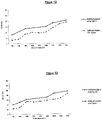
- test specimens in format B (230x64x54 mm) were sawn out using a diamond saw in accordance with DIN EN 1927-5 (March 2013), in accordance with the respective axis of Figures 10-15 specified test temperatures with a holding time of 5 hours each and evaluated.
Landscapes
- Engineering & Computer Science (AREA)
- Mechanical Engineering (AREA)
- Structural Engineering (AREA)
- Architecture (AREA)
- Chemical & Material Sciences (AREA)
- Chemical Kinetics & Catalysis (AREA)
- Civil Engineering (AREA)
- Nozzles (AREA)
Claims (14)
- Tuyère de mélange (8) pour un dispositif d'application de béton par projection (1) pour projeter à sec du béton, en particulier du béton réfractaire, présentanta) un dispositif de production d'aérosol (55) pour la production d'un aérosol à partir d'un matériau d'injection pouvant couler liquide ou sec et d'air de transport,b) un dispositif d'injection d'aérosol (56) pour l'injection de l'aérosol, en particulier au centre, à l'intérieur d'un flux de matériau sec constitué d'un mélange sec,dans laquelle le dispositif de production d'aérosol (55) présente :a) une chambre d'aérosol (20), caractérisée en ce que le dispositif de production d'aérosol (55) présente en outre :b) au moins un canal de passage d'air (21) débouchant dans la chambre d'aérosol (20) pour amener l'air de transport dans la chambre d'aérosol (20) en particulier dans un sens de transport principal (18),c) au moins un canal d'amenée de matériau d'injection (22) débouchant dans la chambre d'aérosol (20) pour amener le matériau d'injection dans la chambre d'aérosol (20),d) une tuyère de pulvérisation (25) disposée sur l'extrémité du canal d'amenée de matériau d'injection (22) pour introduire par pulvérisation le matériau d'injection dans le flux d'air de transport dans la chambre d'aérosol (20).
- Tuyère de mélange (8) selon la revendication 1,
caractérisée en ce que
le dispositif d'injection d'aérosol (56) présente :a) une chambre cyclonique (30),b) un canal d'entrée de mélange sec (44) débouchant dans la chambre cyclonique (30) pour amener le mélange sec dans la chambre cyclonique (30),c) un tube d'injection (32) dépassant à l'intérieur de la chambre cyclonique (30) et se trouvant en communication fluidique avec la chambre d'aérosol (20) pour amener l'aérosol à l'intérieur du flux de matériau sec, dans laquelle de préférence le tube d'injection (32) est disposé de telle sorte que le flux de matériau sec sortant du canal d'entrée de mélange sec (44) atteint le tube d'injection (32) et est ainsi divisé,dans laquelle de préférence le tube d'injection (32) est disposé de telle sorte que le flux de matériau sec est divisé avant que l'aérosol ne soit injecté dans le flux de matériau sec. - Tuyère de mélange (8) selon la revendication 2,
caractérisée en ce que
le tube d'injection (32) est disposé de telle sorte que l'injection de l'aérosol dans le flux de matériau sec est effectuée à l'intérieur de la chambre cyclonique (30) ou le tube d'injection (32) est disposé de telle sorte que l'injection de l'aérosol dans le flux de matériau sec est effectuée à l'extérieur de la chambre cyclonique (30). - Tuyère de mélange (8) selon l'une quelconque des revendications précédentes,
caractérisée en ce que
le dispositif de production d'aérosol (55) est réalisé de telle sorte, en particulier les canaux de passage d'air (21), le canal d'amenée de matériau d'injection (22) et la tuyère de pulvérisation (25) sont disposés et réalisés de telle sorte que l'injection du matériau d'injection est effectuée, de manière préférée au centre, à l'intérieur du flux d'air de transport. - Tuyère de mélange (8) selon l'une quelconque des revendications précédentes,
caractérisée en ce que
la tuyère de mélange (8) présente un axe longitudinal de tuyère (14) ainsi qu'une extrémité d'entrée de tuyère (8a) et une extrémité de sortie de tuyère (8b) opposée à celle-ci dans le sens de l'axe longitudinal de tuyère (14) ainsi qu'un canal d'écoulement ou de transport (15) s'étendant à travers la tuyère de mélange (8) de part en part dans le sens de l'axe longitudinal de tuyère (14), dans laquelle un sens de transport principal (18), s'étendant depuis l'extrémité d'entrée de tuyère (8a) vers l'extrémité de sortie de tuyère (8b), de la tuyère de mélange (8) est de préférence parallèle par rapport à l'axe longitudinal de tuyère (14). - Tuyère de mélange (8) selon l'une quelconque des revendications précédentes,caractérisée en ce quela tuyère de mélange (8) présente une cloison de séparation (19), qui présente l'au moins un canal de passage d'air (21), de manière préférée plusieurs canaux de passage d'air (21), en particulier cylindres creux, lesquels s'étendent à travers la cloison de séparation (19), en particulier dans le sens de transport principal (18), et débouchent dans la chambre d'aérosol (20),dans laquelle de préférence les canaux de passage d'air (21) sont disposés de manière répartie autour de l'axe longitudinal de tuyère (14) vus par rapport à l'axe longitudinal de tuyère (14) dans le sens périphérique et sont tenus à distance de l'axe longitudinal de tuyère (14), dans laquelle les canaux de passage d'air (21) présentent de préférence tous la même distance par rapport à l'axe longitudinal de tuyère (14) et sont tenus à distance les uns des autres de préférence tous à l'identique dans le sens périphérique.
- Tuyère de mélange (8) selon la revendication 6,
caractérisée en ce que
la cloison de séparation (19) présente le canal d'amenée de matériau d'injection (22) pour amener le matériau d'injection dans la chambre d'aérosol (20), dans laquelle le canal d'amenée de matériau d'injection (22) présente une section de canal d'amenée (24), en particulier cylindrique creuse, débouchant dans la chambre d'aérosol (20), dans laquelle la deuxième section de canal d'amenée (24) présente un axe de canal, lequel s'étend de préférence de manière parallèle, de manière préférée coaxialement, par rapport à l'axe longitudinal de tuyère (14). - Tuyère de mélange (8) selon l'une quelconque des revendications précédentes,
caractérisée en ce que
la tuyère de pulvérisation (25) est une tuyère à jet plat, une tuyère à jet lisse, une tuyère à cône creux, une tuyère à cône plein ou une tuyère à brouillard ou est une tuyère de sablage ou une tuyère d'éjection pour des produits en vrac pouvant couler. - Tuyère de mélange (8) selon l'une quelconque des revendications 2 à 8,
caractérisée en ce que
la chambre d'aérosol (20) se trouve en communication fluidique par l'intermédiaire du tube d'injection (32) avec la chambre cyclonique (30). - Tuyère de mélange (8) selon l'une quelconque des revendications 2 à 9,caractérisée en ce quela chambre cyclonique (30) présente une paroi périphérique de chambre (40) et un axe central de chambre (41), lequel est coaxial par rapport à l'axe longitudinal de tuyère (14), dans laquelle la paroi périphérique de chambre (40) présente de préférence une section de paroi conique (40b), qui se rétrécit de telle manière vue dans le sens de transport principal (18) que le mélange sec est aspiré par l'effet Venturi dans la chambre cyclonique (30),dans laquelle de préférence le tube d'injection (32) est tenu à distance de la paroi périphérique de chambre (40) de telle sorte qu'une section transversale d'écoulement y est formée de manière intercalée.
- Tuyère de mélange (8) selon l'une quelconque des revendications 2 à 10,
caractérisée en ce que
le canal d'entrée de mélange sec (44) présente un axe de canal (44a), lequel débouche dans la chambre cyclonique (30) dans le canal d'entrée de mélange de mélange sec (44) dans une zone d'embouchure, forme un angle α de 30 à 90°, de manière préférée de 90°, avec l'axe longitudinal de tuyère (14). - Tuyère de mélange (8) selon l'une quelconque des revendications 2 à 11,caractérisée en ce quela tuyère de mélange (8) présente un canal d'entrée d'air de dérivation (45) pour amener de l'air de dérivation dans la chambre cyclonique (30), dans laquelle le canal d'entrée d'air de dérivation (45) présente une section de canal d'entrée (47) débouchant dans la chambre cyclonique (30), qui débouche, de préférence sur une extrémité côté entrée de la chambre cyclonique (30), dans celle-ci, etdans laquelle de préférence un axe de canal de la section de canal d'entrée (47) est parallèle par rapport à l'axe longitudinal de tuyère (14) ou est incliné par rapport à l'axe longitudinal de tuyère (14) et forme avec celui-ci un angle < 90°,et/ou dans laquelle de préférence l'axe de canal de la section de canal d'entrée (47) est tenu à distance de l'axe longitudinal de tuyère (14),dans laquelle de préférence la deuxième section de canal d'entrée (47) est disposée à l'opposé radialement par rapport au canal d'entrée de mélange sec (44) vue dans une coupe perpendiculairement par rapport à l'axe longitudinal de tuyère (14).
- Dispositif d'application de béton par projection (1) pour appliquer par projection une matière à projet, en particulier une matière à projeter en béton réfractaire, sur une surface, présentant :a) une source d'air comprimé (2) pour fournir de l'air de transport,b) un réservoir de matériau d'injection (4) rempli d'un matériau d'injection sec ou liquide, en particulier d'un liquide d'injection,c) un réservoir de mélange sec (6) rempli d'un mélange sec,d) une tuyère de mélange (8) selon l'une quelconque des revendications précédentes pour mélanger le matériau d'injection à l'air de transport et au mélange sec pour obtenir un mélange de matériaux en particulier préalablement humidifié,e) une tuyère de projection (10) pour appliquer par projection la matière à projeter sur la surface à revêtir,f) un conduit (9) raccordé à la tuyère de mélange (8) pour transporter le mélange de matériaux vers la tuyère de projection (10),g) un réservoir de liquide (11) rempli d'un liquide, en particulier d'un liant liquide,h) de moyens pour mélanger le mélange de matériaux, en particulier préalablement humidifié, au liquide pour obtenir la matière à projeter sur l'extrémité du côté de la tuyère de projection du conduit tubulaire flexible (9) en amont ou dans la tuyère de projection (10),dans lequel de préférence la tuyère de mélange (8) est disposée sur une extrémité côté entrée du conduit tubulaire flexible (9).
- Procédé de projection à sec pour appliquer par projection une matière à projeter, en particulier une matière à projeter en béton réfractaire, sur une surface, de préférence avec un dispositif d'application de béton par projection (1) selon la revendication 13, avec les étapes de procédé suivantes :a) le mélange d'un matériau d'injection sec ou liquide, en particulier d'un liquide d'injection, à l'air de transport pour obtenir un aérosol,b) l'injection de l'aérosol, en particulier au centre, à l'intérieur d'un flux de matériau sec constitué d'un mélange sec et le mélange de l'aérosol au mélange sec pour obtenir un mélange de matériaux,c) le transport du mélange de matériaux au moyen d'un conduit tubulaire flexible (9) vers une tuyère de projection (10),d) le mélange du mélange de matériaux sur l'extrémité du côté de la tuyère de projection du conduit tubulaire flexible (9) dans ou en amont de la tuyère de projection (10) à un liquide pour obtenir la matière à projeter,e) l'application de la matière à projeter sur la surface à revêtir au moyen de la tuyère de projection (10).
Applications Claiming Priority (2)
| Application Number | Priority Date | Filing Date | Title |
|---|---|---|---|
| DE102016124101.6A DE102016124101A1 (de) | 2016-12-12 | 2016-12-12 | Mischdüse für eine Spritzbetonauftragsvorrichtung, sowie Spritzbetonauftragsvorrichtung mit einer derartigen Mischdüse und Spritzbetonauftragsverfahren |
| PCT/EP2017/081749 WO2018108678A1 (fr) | 2016-12-12 | 2017-12-06 | Buse mélangeuse pour dispositif d'application de béton projeté, ainsi que dispositif d'application de béton projeté comprenant une buse mélangeuse de ce type et procédé d'application de béton projeté |
Publications (2)
| Publication Number | Publication Date |
|---|---|
| EP3551408A1 EP3551408A1 (fr) | 2019-10-16 |
| EP3551408B1 true EP3551408B1 (fr) | 2022-04-06 |
Family
ID=60654963
Family Applications (1)
| Application Number | Title | Priority Date | Filing Date |
|---|---|---|---|
| EP17811934.3A Active EP3551408B1 (fr) | 2016-12-12 | 2017-12-06 | Buse mélangeuse pour dispositif d'application de béton projeté, ainsi que dispositif d'application de béton projeté comprenant une buse mélangeuse de ce type et procédé d'application de béton projeté |
Country Status (4)
| Country | Link |
|---|---|
| EP (1) | EP3551408B1 (fr) |
| DE (1) | DE102016124101A1 (fr) |
| RU (1) | RU2730720C1 (fr) |
| WO (1) | WO2018108678A1 (fr) |
Families Citing this family (5)
| Publication number | Priority date | Publication date | Assignee | Title |
|---|---|---|---|---|
| CN111269008B (zh) * | 2020-02-24 | 2022-01-28 | 嘉峪关市长城望宇炉业有限责任公司 | 焦炉炉墙热态修补密封用的含锆陶瓷焊补料和修补方法 |
| CN111758708A (zh) * | 2020-07-29 | 2020-10-13 | 孟海龙 | 一种中药种植用喷药装置 |
| CN112127643A (zh) * | 2020-09-19 | 2020-12-25 | 湖南凡工建筑工程有限公司 | 一种混凝土施工均匀洒水机构 |
| CN113510016B (zh) * | 2021-08-23 | 2024-08-13 | 新疆八一钢铁股份有限公司 | 一种欧冶炉气化炉耐材喷涂装置 |
| DE102024119293A1 (de) | 2024-07-08 | 2026-01-08 | VELCO Gesellschaft für Förder-, Spritz- u. Silo- Anlagen mbH | Vorrichtung und Verfahren zur Verarbeitung von Spritzmassen |
Family Cites Families (15)
| Publication number | Priority date | Publication date | Assignee | Title |
|---|---|---|---|---|
| US2543517A (en) * | 1947-06-09 | 1951-02-27 | Jo Zach Miller Iii | Apparatus for combining and emplacing cementitious substances |
| US2701905A (en) * | 1950-04-10 | 1955-02-15 | Steam Cote Corp | Method of manufacturing concrete pipe |
| SU663804A1 (ru) * | 1972-11-30 | 1979-05-25 | Центральный научно-исследовательский и проектно-конструкторский институт проходческих машин и комплексов для угольной, горной промышленности и подземного строительства | Способ приготовлени бетонной смеси при проведении набрызгбетонных работ |
| SE383910B (sv) | 1974-08-02 | 1976-04-05 | Sandell Bertil | Sett att tillverka betongkonstruktioner |
| AT343339B (de) * | 1975-06-11 | 1978-05-26 | Arge Nassbetonspritzen | Betonspritzmaschine |
| SE411724B (sv) * | 1976-10-26 | 1980-02-04 | Sandell Bertil | Sett och anordning for att en luftstrom tillfora material till ett munstycke |
| GB2025794A (en) | 1978-07-14 | 1980-01-30 | Cooper E | Nozzles |
| US4844340A (en) * | 1986-07-30 | 1989-07-04 | Railway Technical Research Institute | Method and apparatus for spraying an inorganic hydraulic material composition containing reinforcing short fibers |
| EP0738676A1 (fr) | 1995-04-20 | 1996-10-23 | Aliva Aktiengesellschaft | Dispositif pour introduire l'air, des liquides ou des matières solides pulvérulentes dans des conduits pour béton projeté |
| DE19541310A1 (de) * | 1995-11-06 | 1997-05-07 | Suedmo Schleicher Ag | Dosiervorrichtung für pulverförmigen Feststoff |
| DE19851913C2 (de) * | 1998-11-11 | 2001-02-15 | Rombold & Gfroehrer Gmbh & Co | Verfahren zum Herstellen eines Spritzbetons oder Spritzmörtels |
| DE10023170B4 (de) | 2000-05-11 | 2006-04-27 | Kurt Wolf VELCO Gesellschaft für Förder-, Spritz- und Silo-Anlagen mbH | Vorrichtung zur Befeuchtung von trockenen Spritzmassen in der Förderleitung |
| KR20060134125A (ko) | 2004-04-05 | 2006-12-27 | 시나가와 리프랙토리스 오스트랄라시아 피티와이 리미티드 | 슬러리 부착 방법 및 장치 |
| WO2010105049A2 (fr) | 2009-03-11 | 2010-09-16 | Reno Refractories, Inc. | Processus amélioré pour la projection au pistolet de mélanges réfractaires à l'aide d'un équipement conventionnel de projection à sec et mélanges réfractaires destinés à être utilisés dans celui-ci |
| MX2013003307A (es) * | 2010-10-01 | 2013-06-05 | Sika Technology Ag | Aparato de mezcla para mezclas bombeables y metodo relaionado con el mismo. |
-
2016
- 2016-12-12 DE DE102016124101.6A patent/DE102016124101A1/de not_active Withdrawn
-
2017
- 2017-12-06 RU RU2019121630A patent/RU2730720C1/ru active
- 2017-12-06 EP EP17811934.3A patent/EP3551408B1/fr active Active
- 2017-12-06 WO PCT/EP2017/081749 patent/WO2018108678A1/fr not_active Ceased
Also Published As
| Publication number | Publication date |
|---|---|
| EP3551408A1 (fr) | 2019-10-16 |
| RU2730720C1 (ru) | 2020-08-25 |
| DE102016124101A1 (de) | 2018-06-14 |
| WO2018108678A1 (fr) | 2018-06-21 |
Similar Documents
| Publication | Publication Date | Title |
|---|---|---|
| EP3551409B1 (fr) | Dispositif d'application de béton par projection équipé d'une tuyère mélangeuse, et procédé d'application de béton par projection | |
| EP3551408B1 (fr) | Buse mélangeuse pour dispositif d'application de béton projeté, ainsi que dispositif d'application de béton projeté comprenant une buse mélangeuse de ce type et procédé d'application de béton projeté | |
| EP3664980B1 (fr) | Procédé d'impression en 3d de compositions de liant minérales | |
| DE69508695T2 (de) | Nichtabrutschende pumpbare Gussmasse und Verfahren zu deren Auftragung | |
| US5628940A (en) | Process for applying low-cement castable refractory material | |
| EP3600811B1 (fr) | Procédé d'application de compositions de liaison minérale contenant des fibres | |
| CH639591A5 (de) | Verfahren zum herstellen und zum spritzen von beton oder moertel. | |
| EP0289720B1 (fr) | Procédé de projection pour appliquer une couche de béton projeté | |
| DE69625121T2 (de) | Spritzbetriebsverfahren für monolitisches feuerfestes Material | |
| DE69513525T2 (de) | Verfahren und vorrichtung zum mischen, spritzen und aufbringen von zementmaterialien | |
| US6004626A (en) | High pressure/volume process for wet shotcreting a refractory castable | |
| DE69626323T2 (de) | Nasssprühverfahren einer feuerfesten giessbaren zusammensetzung | |
| JP2010007230A (ja) | 吹付けコンクリート製造装置、それを用いた吹付けコンクリートの吹付け方法及び吹付けコンクリートの製造方法 | |
| DE3214858C2 (de) | Vorrichtung zur Herstellung von Formen und Kernen | |
| DE4120409A1 (de) | Verfahren zur aufbringung von schnellabbindenden spruehmaterialien | |
| DE19780838B4 (de) | Verfahren zur Herstellung eines Konstruktionsbeton-Zuschlagstoffes | |
| EP1153861A1 (fr) | Procédé et dispositif pour humidifier, dans une conduite de transport, des matières sèches à injecter | |
| DE29824278U1 (de) | Spritzbindemittel | |
| US8784943B2 (en) | Process for guniting refractory mixes using conventional dry gunning equipment and refractory mixes for use in same | |
| JPH0269343A (ja) | 粉塵結合剤 | |
| JPH0948675A (ja) | 吹付用不定形耐火物 | |
| WO2006106879A1 (fr) | Procede d’application d’un materiau refractaire moulable par pulverisation | |
| DE2041639A1 (de) | Anlage zum Auftragen von pulverfoermigem Material auf die Schalung bzw. auf die Oberflaeche von Einrichtungen | |
| DE202019103998U1 (de) | Frischbeton für die spritztechnische Betonverarbeitung | |
| DE102007028445A1 (de) | Verfahren und Vorrichtung zur Feststoffumhüllung |
Legal Events
| Date | Code | Title | Description |
|---|---|---|---|
| STAA | Information on the status of an ep patent application or granted ep patent |
Free format text: STATUS: UNKNOWN |
|
| STAA | Information on the status of an ep patent application or granted ep patent |
Free format text: STATUS: THE INTERNATIONAL PUBLICATION HAS BEEN MADE |
|
| PUAI | Public reference made under article 153(3) epc to a published international application that has entered the european phase |
Free format text: ORIGINAL CODE: 0009012 |
|
| STAA | Information on the status of an ep patent application or granted ep patent |
Free format text: STATUS: REQUEST FOR EXAMINATION WAS MADE |
|
| 17P | Request for examination filed |
Effective date: 20190625 |
|
| AK | Designated contracting states |
Kind code of ref document: A1 Designated state(s): AL AT BE BG CH CY CZ DE DK EE ES FI FR GB GR HR HU IE IS IT LI LT LU LV MC MK MT NL NO PL PT RO RS SE SI SK SM TR |
|
| AX | Request for extension of the european patent |
Extension state: BA ME |
|
| DAV | Request for validation of the european patent (deleted) | ||
| DAX | Request for extension of the european patent (deleted) | ||
| STAA | Information on the status of an ep patent application or granted ep patent |
Free format text: STATUS: EXAMINATION IS IN PROGRESS |
|
| RAP3 | Party data changed (applicant data changed or rights of an application transferred) |
Owner name: REFRATECHNIK HOLDING GMBH |
|
| 17Q | First examination report despatched |
Effective date: 20210331 |
|
| GRAP | Despatch of communication of intention to grant a patent |
Free format text: ORIGINAL CODE: EPIDOSNIGR1 |
|
| STAA | Information on the status of an ep patent application or granted ep patent |
Free format text: STATUS: GRANT OF PATENT IS INTENDED |
|
| INTG | Intention to grant announced |
Effective date: 20220110 |
|
| GRAS | Grant fee paid |
Free format text: ORIGINAL CODE: EPIDOSNIGR3 |
|
| GRAA | (expected) grant |
Free format text: ORIGINAL CODE: 0009210 |
|
| STAA | Information on the status of an ep patent application or granted ep patent |
Free format text: STATUS: THE PATENT HAS BEEN GRANTED |
|
| AK | Designated contracting states |
Kind code of ref document: B1 Designated state(s): AL AT BE BG CH CY CZ DE DK EE ES FI FR GB GR HR HU IE IS IT LI LT LU LV MC MK MT NL NO PL PT RO RS SE SI SK SM TR |
|
| REG | Reference to a national code |
Ref country code: GB Ref legal event code: FG4D Free format text: NOT ENGLISH |
|
| REG | Reference to a national code |
Ref country code: CH Ref legal event code: EP |
|
| REG | Reference to a national code |
Ref country code: AT Ref legal event code: REF Ref document number: 1480902 Country of ref document: AT Kind code of ref document: T Effective date: 20220415 |
|
| REG | Reference to a national code |
Ref country code: IE Ref legal event code: FG4D Free format text: LANGUAGE OF EP DOCUMENT: GERMAN |
|
| REG | Reference to a national code |
Ref country code: DE Ref legal event code: R096 Ref document number: 502017012932 Country of ref document: DE |
|
| REG | Reference to a national code |
Ref country code: LT Ref legal event code: MG9D |
|
| REG | Reference to a national code |
Ref country code: NL Ref legal event code: MP Effective date: 20220406 |
|
| PG25 | Lapsed in a contracting state [announced via postgrant information from national office to epo] |
Ref country code: NL Free format text: LAPSE BECAUSE OF FAILURE TO SUBMIT A TRANSLATION OF THE DESCRIPTION OR TO PAY THE FEE WITHIN THE PRESCRIBED TIME-LIMIT Effective date: 20220406 |
|
| PG25 | Lapsed in a contracting state [announced via postgrant information from national office to epo] |
Ref country code: SE Free format text: LAPSE BECAUSE OF FAILURE TO SUBMIT A TRANSLATION OF THE DESCRIPTION OR TO PAY THE FEE WITHIN THE PRESCRIBED TIME-LIMIT Effective date: 20220406 Ref country code: PT Free format text: LAPSE BECAUSE OF FAILURE TO SUBMIT A TRANSLATION OF THE DESCRIPTION OR TO PAY THE FEE WITHIN THE PRESCRIBED TIME-LIMIT Effective date: 20220808 Ref country code: NO Free format text: LAPSE BECAUSE OF FAILURE TO SUBMIT A TRANSLATION OF THE DESCRIPTION OR TO PAY THE FEE WITHIN THE PRESCRIBED TIME-LIMIT Effective date: 20220706 Ref country code: LT Free format text: LAPSE BECAUSE OF FAILURE TO SUBMIT A TRANSLATION OF THE DESCRIPTION OR TO PAY THE FEE WITHIN THE PRESCRIBED TIME-LIMIT Effective date: 20220406 Ref country code: HR Free format text: LAPSE BECAUSE OF FAILURE TO SUBMIT A TRANSLATION OF THE DESCRIPTION OR TO PAY THE FEE WITHIN THE PRESCRIBED TIME-LIMIT Effective date: 20220406 Ref country code: GR Free format text: LAPSE BECAUSE OF FAILURE TO SUBMIT A TRANSLATION OF THE DESCRIPTION OR TO PAY THE FEE WITHIN THE PRESCRIBED TIME-LIMIT Effective date: 20220707 Ref country code: FI Free format text: LAPSE BECAUSE OF FAILURE TO SUBMIT A TRANSLATION OF THE DESCRIPTION OR TO PAY THE FEE WITHIN THE PRESCRIBED TIME-LIMIT Effective date: 20220406 Ref country code: ES Free format text: LAPSE BECAUSE OF FAILURE TO SUBMIT A TRANSLATION OF THE DESCRIPTION OR TO PAY THE FEE WITHIN THE PRESCRIBED TIME-LIMIT Effective date: 20220406 Ref country code: BG Free format text: LAPSE BECAUSE OF FAILURE TO SUBMIT A TRANSLATION OF THE DESCRIPTION OR TO PAY THE FEE WITHIN THE PRESCRIBED TIME-LIMIT Effective date: 20220706 |
|
| PG25 | Lapsed in a contracting state [announced via postgrant information from national office to epo] |
Ref country code: RS Free format text: LAPSE BECAUSE OF FAILURE TO SUBMIT A TRANSLATION OF THE DESCRIPTION OR TO PAY THE FEE WITHIN THE PRESCRIBED TIME-LIMIT Effective date: 20220406 Ref country code: PL Free format text: LAPSE BECAUSE OF FAILURE TO SUBMIT A TRANSLATION OF THE DESCRIPTION OR TO PAY THE FEE WITHIN THE PRESCRIBED TIME-LIMIT Effective date: 20220406 Ref country code: LV Free format text: LAPSE BECAUSE OF FAILURE TO SUBMIT A TRANSLATION OF THE DESCRIPTION OR TO PAY THE FEE WITHIN THE PRESCRIBED TIME-LIMIT Effective date: 20220406 Ref country code: IS Free format text: LAPSE BECAUSE OF FAILURE TO SUBMIT A TRANSLATION OF THE DESCRIPTION OR TO PAY THE FEE WITHIN THE PRESCRIBED TIME-LIMIT Effective date: 20220806 |
|
| REG | Reference to a national code |
Ref country code: DE Ref legal event code: R097 Ref document number: 502017012932 Country of ref document: DE |
|
| PG25 | Lapsed in a contracting state [announced via postgrant information from national office to epo] |
Ref country code: SM Free format text: LAPSE BECAUSE OF FAILURE TO SUBMIT A TRANSLATION OF THE DESCRIPTION OR TO PAY THE FEE WITHIN THE PRESCRIBED TIME-LIMIT Effective date: 20220406 Ref country code: SK Free format text: LAPSE BECAUSE OF FAILURE TO SUBMIT A TRANSLATION OF THE DESCRIPTION OR TO PAY THE FEE WITHIN THE PRESCRIBED TIME-LIMIT Effective date: 20220406 Ref country code: RO Free format text: LAPSE BECAUSE OF FAILURE TO SUBMIT A TRANSLATION OF THE DESCRIPTION OR TO PAY THE FEE WITHIN THE PRESCRIBED TIME-LIMIT Effective date: 20220406 Ref country code: EE Free format text: LAPSE BECAUSE OF FAILURE TO SUBMIT A TRANSLATION OF THE DESCRIPTION OR TO PAY THE FEE WITHIN THE PRESCRIBED TIME-LIMIT Effective date: 20220406 Ref country code: DK Free format text: LAPSE BECAUSE OF FAILURE TO SUBMIT A TRANSLATION OF THE DESCRIPTION OR TO PAY THE FEE WITHIN THE PRESCRIBED TIME-LIMIT Effective date: 20220406 Ref country code: CZ Free format text: LAPSE BECAUSE OF FAILURE TO SUBMIT A TRANSLATION OF THE DESCRIPTION OR TO PAY THE FEE WITHIN THE PRESCRIBED TIME-LIMIT Effective date: 20220406 |
|
| PLBE | No opposition filed within time limit |
Free format text: ORIGINAL CODE: 0009261 |
|
| STAA | Information on the status of an ep patent application or granted ep patent |
Free format text: STATUS: NO OPPOSITION FILED WITHIN TIME LIMIT |
|
| 26N | No opposition filed |
Effective date: 20230110 |
|
| PG25 | Lapsed in a contracting state [announced via postgrant information from national office to epo] |
Ref country code: AL Free format text: LAPSE BECAUSE OF FAILURE TO SUBMIT A TRANSLATION OF THE DESCRIPTION OR TO PAY THE FEE WITHIN THE PRESCRIBED TIME-LIMIT Effective date: 20220406 |
|
| PG25 | Lapsed in a contracting state [announced via postgrant information from national office to epo] |
Ref country code: SI Free format text: LAPSE BECAUSE OF FAILURE TO SUBMIT A TRANSLATION OF THE DESCRIPTION OR TO PAY THE FEE WITHIN THE PRESCRIBED TIME-LIMIT Effective date: 20220406 |
|
| P01 | Opt-out of the competence of the unified patent court (upc) registered |
Effective date: 20230519 |
|
| REG | Reference to a national code |
Ref country code: CH Ref legal event code: PL |
|
| GBPC | Gb: european patent ceased through non-payment of renewal fee |
Effective date: 20221206 |
|
| REG | Reference to a national code |
Ref country code: BE Ref legal event code: MM Effective date: 20221231 |
|
| PG25 | Lapsed in a contracting state [announced via postgrant information from national office to epo] |
Ref country code: LU Free format text: LAPSE BECAUSE OF NON-PAYMENT OF DUE FEES Effective date: 20221206 |
|
| PG25 | Lapsed in a contracting state [announced via postgrant information from national office to epo] |
Ref country code: LI Free format text: LAPSE BECAUSE OF NON-PAYMENT OF DUE FEES Effective date: 20221231 Ref country code: IE Free format text: LAPSE BECAUSE OF NON-PAYMENT OF DUE FEES Effective date: 20221206 Ref country code: GB Free format text: LAPSE BECAUSE OF NON-PAYMENT OF DUE FEES Effective date: 20221206 Ref country code: CH Free format text: LAPSE BECAUSE OF NON-PAYMENT OF DUE FEES Effective date: 20221231 |
|
| PG25 | Lapsed in a contracting state [announced via postgrant information from national office to epo] |
Ref country code: FR Free format text: LAPSE BECAUSE OF NON-PAYMENT OF DUE FEES Effective date: 20221231 Ref country code: BE Free format text: LAPSE BECAUSE OF NON-PAYMENT OF DUE FEES Effective date: 20221231 |
|
| PG25 | Lapsed in a contracting state [announced via postgrant information from national office to epo] |
Ref country code: IT Free format text: LAPSE BECAUSE OF FAILURE TO SUBMIT A TRANSLATION OF THE DESCRIPTION OR TO PAY THE FEE WITHIN THE PRESCRIBED TIME-LIMIT Effective date: 20220406 |
|
| REG | Reference to a national code |
Ref country code: AT Ref legal event code: MM01 Ref document number: 1480902 Country of ref document: AT Kind code of ref document: T Effective date: 20221206 |
|
| PG25 | Lapsed in a contracting state [announced via postgrant information from national office to epo] |
Ref country code: HU Free format text: LAPSE BECAUSE OF FAILURE TO SUBMIT A TRANSLATION OF THE DESCRIPTION OR TO PAY THE FEE WITHIN THE PRESCRIBED TIME-LIMIT; INVALID AB INITIO Effective date: 20171206 |
|
| PG25 | Lapsed in a contracting state [announced via postgrant information from national office to epo] |
Ref country code: AT Free format text: LAPSE BECAUSE OF NON-PAYMENT OF DUE FEES Effective date: 20221206 |
|
| PG25 | Lapsed in a contracting state [announced via postgrant information from national office to epo] |
Ref country code: CY Free format text: LAPSE BECAUSE OF FAILURE TO SUBMIT A TRANSLATION OF THE DESCRIPTION OR TO PAY THE FEE WITHIN THE PRESCRIBED TIME-LIMIT Effective date: 20220406 Ref country code: AT Free format text: LAPSE BECAUSE OF NON-PAYMENT OF DUE FEES Effective date: 20221206 |
|
| PG25 | Lapsed in a contracting state [announced via postgrant information from national office to epo] |
Ref country code: MK Free format text: LAPSE BECAUSE OF FAILURE TO SUBMIT A TRANSLATION OF THE DESCRIPTION OR TO PAY THE FEE WITHIN THE PRESCRIBED TIME-LIMIT Effective date: 20220406 |
|
| PG25 | Lapsed in a contracting state [announced via postgrant information from national office to epo] |
Ref country code: MC Free format text: LAPSE BECAUSE OF FAILURE TO SUBMIT A TRANSLATION OF THE DESCRIPTION OR TO PAY THE FEE WITHIN THE PRESCRIBED TIME-LIMIT Effective date: 20220406 |
|
| PG25 | Lapsed in a contracting state [announced via postgrant information from national office to epo] |
Ref country code: TR Free format text: LAPSE BECAUSE OF FAILURE TO SUBMIT A TRANSLATION OF THE DESCRIPTION OR TO PAY THE FEE WITHIN THE PRESCRIBED TIME-LIMIT Effective date: 20220406 Ref country code: MC Free format text: LAPSE BECAUSE OF FAILURE TO SUBMIT A TRANSLATION OF THE DESCRIPTION OR TO PAY THE FEE WITHIN THE PRESCRIBED TIME-LIMIT Effective date: 20220406 |
|
| PG25 | Lapsed in a contracting state [announced via postgrant information from national office to epo] |
Ref country code: MT Free format text: LAPSE BECAUSE OF FAILURE TO SUBMIT A TRANSLATION OF THE DESCRIPTION OR TO PAY THE FEE WITHIN THE PRESCRIBED TIME-LIMIT Effective date: 20220406 |
|
| PG25 | Lapsed in a contracting state [announced via postgrant information from national office to epo] |
Ref country code: BG Free format text: LAPSE BECAUSE OF FAILURE TO SUBMIT A TRANSLATION OF THE DESCRIPTION OR TO PAY THE FEE WITHIN THE PRESCRIBED TIME-LIMIT Effective date: 20220406 |
|
| PG25 | Lapsed in a contracting state [announced via postgrant information from national office to epo] |
Ref country code: BG Free format text: LAPSE BECAUSE OF FAILURE TO SUBMIT A TRANSLATION OF THE DESCRIPTION OR TO PAY THE FEE WITHIN THE PRESCRIBED TIME-LIMIT Effective date: 20220406 |
|
| PGFP | Annual fee paid to national office [announced via postgrant information from national office to epo] |
Ref country code: DE Payment date: 20260225 Year of fee payment: 9 |