EP3551514B1 - Maître cylindre avec capteur de position et accouplement entre les deux. - Google Patents
Maître cylindre avec capteur de position et accouplement entre les deux. Download PDFInfo
- Publication number
- EP3551514B1 EP3551514B1 EP17791006.4A EP17791006A EP3551514B1 EP 3551514 B1 EP3551514 B1 EP 3551514B1 EP 17791006 A EP17791006 A EP 17791006A EP 3551514 B1 EP3551514 B1 EP 3551514B1
- Authority
- EP
- European Patent Office
- Prior art keywords
- arrangement
- section
- coupling
- piston
- master cylinder
- Prior art date
- Legal status (The legal status is an assumption and is not a legal conclusion. Google has not performed a legal analysis and makes no representation as to the accuracy of the status listed.)
- Active
Links
Images



Classifications
-
- B—PERFORMING OPERATIONS; TRANSPORTING
- B60—VEHICLES IN GENERAL
- B60T—VEHICLE BRAKE CONTROL SYSTEMS OR PARTS THEREOF; BRAKE CONTROL SYSTEMS OR PARTS THEREOF, IN GENERAL; ARRANGEMENT OF BRAKING ELEMENTS ON VEHICLES IN GENERAL; PORTABLE DEVICES FOR PREVENTING UNWANTED MOVEMENT OF VEHICLES; VEHICLE MODIFICATIONS TO FACILITATE COOLING OF BRAKES
- B60T11/00—Transmitting braking action from initiating means to ultimate brake actuator without power assistance or drive or where such assistance or drive is irrelevant
- B60T11/10—Transmitting braking action from initiating means to ultimate brake actuator without power assistance or drive or where such assistance or drive is irrelevant transmitting by fluid means, e.g. hydraulic
- B60T11/16—Master control, e.g. master cylinders
- B60T11/20—Tandem, side-by-side, or other multiple master cylinder units
-
- B—PERFORMING OPERATIONS; TRANSPORTING
- B60—VEHICLES IN GENERAL
- B60T—VEHICLE BRAKE CONTROL SYSTEMS OR PARTS THEREOF; BRAKE CONTROL SYSTEMS OR PARTS THEREOF, IN GENERAL; ARRANGEMENT OF BRAKING ELEMENTS ON VEHICLES IN GENERAL; PORTABLE DEVICES FOR PREVENTING UNWANTED MOVEMENT OF VEHICLES; VEHICLE MODIFICATIONS TO FACILITATE COOLING OF BRAKES
- B60T11/00—Transmitting braking action from initiating means to ultimate brake actuator without power assistance or drive or where such assistance or drive is irrelevant
- B60T11/10—Transmitting braking action from initiating means to ultimate brake actuator without power assistance or drive or where such assistance or drive is irrelevant transmitting by fluid means, e.g. hydraulic
- B60T11/16—Master control, e.g. master cylinders
-
- B—PERFORMING OPERATIONS; TRANSPORTING
- B60—VEHICLES IN GENERAL
- B60T—VEHICLE BRAKE CONTROL SYSTEMS OR PARTS THEREOF; BRAKE CONTROL SYSTEMS OR PARTS THEREOF, IN GENERAL; ARRANGEMENT OF BRAKING ELEMENTS ON VEHICLES IN GENERAL; PORTABLE DEVICES FOR PREVENTING UNWANTED MOVEMENT OF VEHICLES; VEHICLE MODIFICATIONS TO FACILITATE COOLING OF BRAKES
- B60T17/00—Component parts, details, or accessories of power brake systems not covered by groups B60T8/00, B60T13/00 or B60T15/00, or presenting other characteristic features
- B60T17/18—Safety devices; Monitoring
- B60T17/22—Devices for monitoring or checking brake systems; Signal devices
- B60T17/221—Procedure or apparatus for checking or keeping in a correct functioning condition of brake systems
-
- B—PERFORMING OPERATIONS; TRANSPORTING
- B60—VEHICLES IN GENERAL
- B60T—VEHICLE BRAKE CONTROL SYSTEMS OR PARTS THEREOF; BRAKE CONTROL SYSTEMS OR PARTS THEREOF, IN GENERAL; ARRANGEMENT OF BRAKING ELEMENTS ON VEHICLES IN GENERAL; PORTABLE DEVICES FOR PREVENTING UNWANTED MOVEMENT OF VEHICLES; VEHICLE MODIFICATIONS TO FACILITATE COOLING OF BRAKES
- B60T17/00—Component parts, details, or accessories of power brake systems not covered by groups B60T8/00, B60T13/00 or B60T15/00, or presenting other characteristic features
- B60T17/18—Safety devices; Monitoring
Definitions
- the present invention relates generally to the technical field of master cylinder assemblies and, more particularly, to master cylinder assemblies for motor vehicle brake systems. More precisely, the present invention relates to a master brake cylinder arrangement in which an actuation of the brake pedal can be detected by means of a position transmitter element.
- a position transmitter element which can be displaced in accordance with the actuation of the brake pedal, this displacement being detected by means of a detection unit.
- rod-shaped position transmitter elements come into consideration, which are coupled to the piston of a master brake cylinder for common displacement.
- DE 39 28 874 C1 a hydraulic dual-circuit brake system, the braking device of which comprises a front-axle brake circuit and a rear-axle brake circuit, the brake circuits each having an associated output pressure chamber.
- the pressure chambers are movably delimited by master cylinder pistons, each master cylinder piston being assigned a position sensor.
- An electronic control device is provided for processing the position transmitter output signals, which in turn emits control signals for a valve arrangement.
- the electronic control unit further comprises a comparator, which based on the Position sensor output signals compares the positions of the pistons of the braking device with one another.
- a master brake cylinder arrangement is to be specified which enables reliable detection of a brake pedal actuation.
- the pressure piston unit can comprise a piston, for example in the form of a pressure and / or brake piston, which is guided displaceably in a cylinder bore of the master brake cylinder arrangement.
- the housing arrangement can comprise a cylinder housing of the master brake cylinder arrangement.
- the pressure piston unit and the cylinder bore (and / or the cylinder housing) can jointly delimit the pressure chamber.
- the volume of the pressure chamber can be varied so that, in a known manner, pressure is exerted on the pedal counterforce simulator or in the event of a system failure a brake pressure in a hydraulic brake circuit coupled to the master brake cylinder arrangement can be changed directly.
- the master brake cylinder arrangement can also comprise a plurality of such pressure piston units, which are arranged, for example, in a tandem design. These can also define a corresponding plurality of pressure chambers.
- the pressure piston unit can be constructed in several parts.
- the pressure piston unit can comprise a substantially cylindrical piston. This can be displaced directly into and / or out of the pressure chamber, at least in sections.
- Further elements of the pressure piston unit can be attached to the piston, for example a receiving bushing for a connecting section of the force input member and / or a driver element (for example a driver disk). These elements can be arranged at least partially in a cylindrical blind hole or recess in the piston.
- the driver element can also protrude generally radially from the piston, for example in order to form a region of the pressure piston unit axially opposite the position transmitter element.
- the force input member can be designed as a generally cylindrical element and / or piston-like.
- the coupling with the plunger unit can be non-positive and / or positive (for example by caulking or jointly bringing them into contact).
- At least indirect mechanical coupling can also take place with the brake pedal.
- the force input element can also be displaceable along the displacement axis, it being able to convert a brake pedal actuation into a displacement of the pressure piston unit along the displacement axis.
- the position transmitter element can be designed as a generally elongated and / or cylindrical element. According to one example, the position transmitter element is essentially rod-shaped and / or at least in sections with a rounded, oval or circular cross section.
- the position transmitter element can also be referred to as a position transmitter rod or sensor pin.
- the position transmitter element can comprise a metallic and, in particular, a magnetic material and / or can generally be set up with the detection unit for a To interact with position detection.
- the detection unit can comprise a magnetic field sensor.
- the position transmitter element can be coupled or coupled to the pressure piston unit or the force input member in order to be displaced together with them. This can be done using the coupling arrangement explained below.
- the displacement of the position transmitter element can also take place essentially along the displacement axis. In particular, the position transmitter element can be displaced along an axis spaced apart from the displacement axis but parallel thereto.
- the detection unit can detect the movements of the position transmitter element by means of a suitable sensor unit, for example a magnetic field sensor unit comprising a Hall sensor.
- the detection unit can also be comprised by an electromechanical brake actuator unit or interact with it.
- the detection unit can be part of a sensor unit for detecting an operating parameter of the brake actuator unit, such as a current position of an electric motor of this unit.
- the detection unit can generally be designed to generate signals in accordance with the displacement of the position transmitter element. These can be evaluated by a control unit.
- the control unit can be included in the detection unit or at least be connectable to it.
- the coupling arrangement can generally form a unit interposed between the position transmitter element and the at least one element of the piston arrangement. This can in particular include mechanical interconnection or intermediate positioning, so that the piston arrangement and the position transmitter element are connected indirectly via the coupling arrangement. Apart from the coupling arrangement, essentially no further indirect and / or direct mechanical couplings can be provided between the position transmitter element and the piston arrangement.
- a force transmission between the piston arrangement and the position transmitter element for joint displacement can take place essentially via the coupling arrangement and in particular essentially exclusively via the coupling arrangement.
- the coupling arrangement can comprise and / or form an assembly which is designed separately from the piston arrangement and / or can be handled separately. This can be connected to the at least one element of the piston arrangement and, for example, can be fastened directly thereto.
- the coupling arrangement can comprise a separately formed element which can be connected to the piston arrangement and which optionally comprises at least one of the first and second sections explained below.
- the coupling arrangement or its possible separately formed element can be formed in one piece and in particular made from a sheet metal material (for example as a bent sheet metal or stamped part).
- the axially rigid coupling of the position transmitter element and the piston arrangement can relate to a limiting or essentially complete suppression of an axial relative movement between the said elements along the displacement axis.
- the coupling arrangement can be designed such that the position detection element and the piston arrangement can be moved together along the displacement axis without significant axial relative movements or axial play occurring between these elements.
- the coupling arrangement can be designed to enable a relative rotation between the position transmitter element and the piston arrangement about the displacement axis.
- the piston arrangement can slip relative to the coupling arrangement, so to speak, without a significant transfer of this rotational movement to the position transmitter element, whereby a rotational transverse force load on the position transmitter element is reduced or prevented.
- the coupling arrangement can decouple the position transmitter element and the piston arrangement essentially in a rotational manner, this particularly relating to a rotation about the displacement axis.
- the coupling arrangement can thus generally be designed to transmit essentially only axial forces between the elements mentioned, but not rotational forces about the displacement axis.
- the coupling arrangement for coupling the relevant elements can in particular with a driver element of the Interact pressure piston unit and / or a free end of the position transmitter element.
- the coupling arrangement comprises a first section which is designed to couple the coupling arrangement to the at least one element of the piston arrangement.
- the coupling can relate to a direct and / or mechanical coupling.
- the first section can in particular be axially coupled to the element of the piston arrangement, in particular axially rigid.
- the first section can be decoupled from the piston arrangement in a rotational manner, despite any axially rigid coupling therewith.
- the first section can provide the rotational degree of freedom between the position transmitter element and the element of the piston arrangement at least in part, for the most part or essentially completely. Additionally or alternatively, the first section can provide the axially rigid coupling between the position transmitter element and the element of the piston arrangement, at least partially, for the most part or essentially completely.
- the first section can furthermore be designed to interact with a coupling surface of the piston arrangement and in particular to slide off relative to it.
- the coupling surface can be encompassed by a coupling region of the piston arrangement or form this.
- the sliding can relate to sliding along and / or on the coupling surface (in particular wherein the coupling surface is moved and the first section remains essentially stationary). Additionally or alternatively, this can relate to a relative sliding in the circumferential direction of the at least one element of the piston arrangement, wherein the circumferential direction can run around the displacement axis.
- the terms axial and radial can relate to the displacement axis.
- the circumferential direction can relate to a direction or extension about the displacement axis, in particular within a plane orthogonal to this axis.
- the coupling surface can be provided, for example, on an outer peripheral surface of the pressure piston unit. This can in particular relate to an outer circumferential surface of the piston and / or a possible driver element.
- the coupling surface can define an annular region. This can be essentially parallel to and around the axis of displacement extend.
- the coupling surface can also be inclined relative to the displacement axis, that is to say for example define a conical ring section.
- the coupling surface can run essentially continuously and / or smoothly.
- the coupling surface can be essentially free of areas or structures that could hinder any relative sliding of the first section.
- the coupling surface can be formed in a region of the piston arrangement which has a larger diameter than a section of the piston arrangement delimiting the pressure chamber.
- the area can be axially opposite a free end of the position transmitter element, for example in order to facilitate coupling therewith.
- the coupling surface can be formed on an outer circumferential surface of the mentioned area.
- the said enlarged diameter area can be provided by a drive plate or a comparable drive element which protrudes radially beyond the diameter of the piston arrangement.
- the coupling surface can be formed at a higher level on a driver element which is arranged on an end region of the piston arrangement facing away from the pressure chamber.
- the driver element can be designed as a driver disk and / or provide a contact surface for a return spring of the piston arrangement.
- the driver element can furthermore form an axial closing element of the piston arrangement (that is to say, for example, define an axial end region thereof).
- the driver element can face an input opening for the force input member and / or can be axially opposite it.
- a further development provides that at least one of the first section and the coupling surface is formed with a recess in which the other of the first section and the coupling surface is at least partially received, and in particular, the recess comprising a groove running in the circumferential direction .
- the recess can define a guide axis for the coupling arrangement to slide off and / or generally a guide axis for the relative rotation between the position transmitter element and the piston arrangement by means of the coupling arrangement.
- the recess can be generally elongated and / or substantially suppress axial relative movements between the first section and the coupling surface. In other words, the recess can be designed to connect the first section and the coupling surface to one another essentially without axial play.
- a rotation in the circumferential direction or around the Displacement axis
- the recess is provided as a groove running in the circumferential direction, which can in particular be designed continuously or completely circumferentially, so that complete rotation about the displacement axis is made possible.
- the recess can be designed in such a way that a relative rotation of at least 360 ° about the displacement axis between the first section and the coupling surface is made possible.
- the recess can define a substantially annular recess.
- the recess In the event that the recess is formed in the first section, it can be an internally circumferential recess or groove that faces the displacement axis, for example. If, on the other hand, the recess is formed in the coupling surface, it can be an externally encircling recess or groove which, for example, faces away from the displacement axis.
- the respective other element of the first section and coupling surface can comprise a projecting area, in particular projecting radially. This can be brought into engagement with the recess and be guided or slide along it (in particular in the circumferential direction and / or around the displacement axis). This is preferably done with an axially backlash-free coupling between these elements.
- the recess can generally provide an axial form fit between the piston arrangement and the coupling arrangement.
- the first section is coupled or can be coupled to the piston arrangement with an elastic deformation.
- the first section can thus maintain a certain degree of elastic deformation even in the attached state.
- the first section can be held on the piston arrangement in a defined manner.
- this can be used to set defined frictional forces between the elements mentioned, in particular in order to influence a possible rotational relative movement here between.
- the elastic deformation only occurs in the assembly process and, after assembly, the coupling arrangement is coupled to the piston arrangement essentially in an undeformed state.
- the first section can comprise an annular region or be designed as such, the annular region spanning an angular range of at least approximately 120 °.
- the annular region can extend around the displacement axis and / or an outer circumferential surface of the coupling arrangement.
- the angular range can relate to an angular range around or in relation to the axis of displacement.
- the annular area can be completely or almost completely closed.
- the annular region can include a circumferential opening of no more than about 180 °, no more than about 90 ° or no more than about 30 °.
- the angular range can span at least approx. 180 °, approx. 270 ° or approx. 330 °.
- the coupling arrangement can comprise a second section which is designed to couple the coupling arrangement to the position transmitter element.
- the second section can essentially merge directly into the first section or at least partially or completely overlap with it.
- the first and / or the second section can each also comprise several individual areas that are not directly related. For example, several areas can be provided on the coupling arrangement, which together act as a second section of the coupling arrangement for coupling to the position transmitter element. The same applies to the first section.
- the second section can be angled from the first section and / or protrude from it.
- the second section can protrude axially and / or radially from the first section.
- the second section extends, starting from the first section, in the direction of the position transmitter element and / or the pressure chamber of the master brake cylinder arrangement.
- the first and second sections can furthermore be comprised or formed by a one-piece component.
- the second section is designed to form a form fit with the position transmitter element.
- the second section can provide, for example, an undercut, a latching area, a clamping section and / or an opening in order to interact with the position transmitter element and in particular to come into engagement with it.
- the form fit can in particular limit or essentially completely suppress an axial relative movement of the coupling arrangement and position transmitter element.
- the form fit be provided in such a way that the coupling of the position transmitter element and the coupling arrangement is essentially free of axial play and / or axially immovable.
- the form fit can also take place radially and / or in the circumferential or rotational direction around the displacement axis.
- the second section can be designed to form a force fit with the position detection element. This can be achieved, for example, in that the second section is coupled to the position detection element with an elastic deformation of at least one of the second section in the position transmitter element (for example as part of a latching).
- the position transmitter element can be coupled or can be coupled to the coupling arrangement with an at least local elastic deformation of the second section.
- a free end of the position transmitter element can have a larger cross-sectional dimension (for example a larger diameter) than a receiving area of the second section, so that the latter is elastically deformed.
- frictional forces can be generated, which can in particular act permanently for a reliable coupling.
- the widened area springs back at least partially after an axial insertion of the position transmitter element and thereby forms a positive locking connection with the free end of the position transmitter element.
- the frictional connection can be accompanied by frictional forces that support an axially play-free coupling and / or relative axial immobility between the second section and position transmitter element. Furthermore, both a possible form fit and a possible force fit can take place at a higher level in such a way that the second section and the position sensor element are coupled essentially without play in the direction of rotation about the displacement axis and / or are immovable relative to one another.
- the coupling arrangement and in particular a possible second section thereof can preload the position transmitter element against the at least one element of the piston arrangement.
- This can take place in that a coupling of the coupling arrangement and position transmitter element takes place under elastic deformation (in particular of the coupling arrangement).
- the prestressing can in particular by means of axially acting on the position transmitter element Restoring forces can be achieved, which are generated, for example, as a result of an elastic deformation of the coupling arrangement.
- the position transmitter element can be pushed or held in contact with the element of the piston arrangement (for example a driver disk). This also makes it possible to prevent axial play and / or axial relative movement between the position transmitter element and the piston arrangement.
- the second section protrudes axially with respect to the first section or that the second section is formed by a recess area in the first section.
- the first section can have an axial recess, an axial recess, an axial blind hole and / or a substantially axially extending latching area, which can each form the second section.
- the second section can in particular extend in the direction of the position transmitter element or the pressure chamber.
- the coupling arrangement is designed in such a way that a maximum radial extension of the piston arrangement (for example a largest diameter thereof) by no more than approx. 25%, no more than approx. 10% or no more than approx. 5% is exceeded.
- the coupling arrangement can be designed to protrude only slightly or not at all radially from the piston arrangement.
- the coupling arrangement can furthermore comprise a fastening element, in particular in order to permanently couple the position transmitter element to the coupling arrangement.
- a fastening element in particular in order to permanently couple the position transmitter element to the coupling arrangement.
- This can be formed separately from the first and second sections and be selectively connectable to the second section, for example.
- the fastening element can be a fastening clip, a fastening pin or the like.
- the fastening element can exert a fastening force, for example in order to fasten the second section and the position transmitter element to one another or to brace them against one another.
- a form fit between the second section and the position transmitter element can be produced and / or reinforced under the action of the fastening element.
- the fastening element can be set up to exert a fastening force such that the second section comes into engagement with the position transmitter element and / or is held in engagement therewith.
- the second section and / or the position transmitter element can also be elastically deformed at least locally under the action of the fastening element.
- the position transmitter element can furthermore comprise an end section which is designed to interact with the second section of the coupling arrangement.
- the end section can comprise a free end or a free end region of the position transmitter element or be formed by this. This end region can comprise a diameter step in order to be coupled to the second section.
- the free end section can in particular comprise an end of the position transmitter element facing away from the detection unit.
- the end section can also come into contact with a predetermined area of the coupling arrangement or of the at least one element of the piston arrangement. This can additionally secure the axial position of the position transmitter element.
- a predetermined area of the coupling arrangement or of the at least one element of the piston arrangement can additionally secure the axial position of the position transmitter element.
- an end piece of the end section which can follow a diameter step in the end section, can be brought into such a system.
- this system can be supported by exerting forces on the position transmitter element and / or the coupling arrangement or piston arrangement.
- the coupling arrangement can, for example, be elastically deformed in a predetermined manner in order to generate restoring forces which force the position transmitter element into a corresponding abutment.
- the second section spans the end section at least partially axially.
- the second section can extend axially along the end section and / or at least partially receive it.
- the second section can be at least partially axial run parallel to the end section and / or also radially to it. This can also take place over different areas or subsections of the second section.
- the second section can comprise a substantially axially extending section as well as a substantially radially extending section.
- the axial section can merge into the second section of the coupling arrangement and the radial section can be angled from the axial section, in particular in the direction of the end section of the position transmitter element.
- the end section can be spanned axially at least by the axial section.
- a master brake cylinder arrangement 10 is shown in a sectional view containing a displacement axis V.
- the master cylinder assembly 10 includes a housing assembly 12 that receives a piston assembly 13.
- the housing arrangement 12 comprises a first housing part 14 which is cylindrical in sections and which provides an input chamber 16 for a force input member 19.
- the first housing part 14 is designed as an element that can be handled separately from a second housing part 18, but is firmly screwed to it.
- a fastening region 27 for fastening the master brake cylinder arrangement 10 in the engine compartment of a vehicle is formed on the first housing part 14.
- the piston arrangement 13 comprises a first piston 20 which is coupled to the force input member 19. Furthermore, the piston arrangement 13 comprises a second piston 22, which is coupled to the first piston 20 via a return spring 24, among other things.
- the pistons 20, 24 delimit a pressure chamber 28 with a cylinder bore 26 extending axially along the displacement axis V.
- the pressure chambers 28 can each be coupled in a known manner to a pedal counterforce simulator, a brake fluid reservoir or, in the event of a system failure, directly to a brake circuit of a motor vehicle (not shown ).
- the force input member 19 is designed as a multi-part piston-shaped element. At its end facing away from the first housing part 14, the force input member 19 comprises a coupling section 26 for coupling to a brake pedal (not shown). As will be explained in detail below, the force input member 19 can also be displaced along a displacement axis V relative to the housing arrangement 12 and, in particular, can be pushed into and withdrawn from the first housing part 14.
- the force input member 19 extends through an input opening 36 of the first housing part 14 into an axial blind hole 32 in the first piston 20, the blind hole 32 facing the input opening 36.
- an end of the force input member 19 facing the first piston 20 is caulked with a receiving sleeve 38 of the first piston 20. Consequently, a displacement movement of the force input member 19 can be transmitted to the first piston and, via the restoring spring 24, also to the second piston 20, 22.
- a driver element in the form of a driver disk 40 is also screwed into the blind hole 32. This has a larger outer diameter than the first piston 20, but also than the second piston 22 or the cylinder bore 26.
- a further return spring 24 is arranged between the drive plate 40 and an opposite end face region of the first housing part 14. This receives the first piston 20 essentially coaxially and extends along the displacement axis V.
- Figure 1 shows the master cylinder arrangement 10 in a starting position or, in other words, in a braking inactive rest position.
- the force input element 19 is activated in accordance with a brake pedal operation Figure 1 moved to the left along the displacement axis V.
- the pistons 20, 22 move within the cylinder bore 26 and reduce the volume of the respectively assigned pressure chambers 28.
- the return springs 24 are compressed in the process. If the driver no longer exerts an actuating force on the brake pedal or the force input member 19, the return springs 26 push the pistons 20, 22 back into their starting position.
- the piston arrangement 13 comprises the two pistons 20, 22 as well as the force input member 19 and the return springs 24 positioned between them. Overall, the piston arrangement 13 is also designed in a known manner according to the tandem cylinder design.
- the actual pressure piston unit of the piston arrangement 13, on the other hand, only comprises the pistons 20, 22, the first piston 20 being constructed in several parts and also comprising the driver plate 40 described above.
- a coupling arrangement 42 is also arranged on the drive plate 40, via which it is coupled to a rod-shaped position transmitter element 44.
- the position transmitter element 44 has a longitudinal axis L which extends parallel to the displacement axis V. Furthermore, the position transmitter element 44 has an essentially circular cross section with a diameter that varies in the end regions.
- FIG. 1 the master brake cylinder arrangement 10 and in particular the position transmitter element 44 are not shown in full. However, one recognizes a first free end section 46 of the position transmitter element 44, which interacts with the coupling arrangement 42. Proceeding from this, the position transmitter element 44 extends in a straight line along the longitudinal axis L. A second end section 47 opposite the first end section 46 (see FIG Figure 2A ) of the position transmitter element 44 is designed to be coupled mechanically with no play to a downstream detection unit. Movements of the second end section can therefore be detected in a known manner by a schematically indicated detection unit 48 which comprises a magnetic field sensor (for example a Hall sensor).
- a schematically indicated detection unit 48 which comprises a magnetic field sensor (for example a Hall sensor).
- the position transmitter element 44 and the driver plate 40 are essentially axially rigid or, in other words, axially backlash-free coupled to one another according to the example shown. This takes place via the coupling arrangement 42 explained below. This is designed to essentially completely suppress an axial relative movement between the position transmitter element 44 and the drive plate 40.
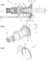
- FIG. 2A shows only a section of a master cylinder arrangement 10, which is analogous to the example from Figure 1 is trained. It shows Figure 2A a partial sectional view of this section, whereas Figure 2B includes a perspective view thereof.
- Figure 2A shows only a section of a master cylinder arrangement 10, which is analogous to the example from Figure 1 is trained. It shows Figure 2A a partial sectional view of this section, whereas Figure 2B includes a perspective view thereof.
- the first piston 20 and the associated return springs 24 can be seen.
- the force input member 19 and the drive plate 40 coupled to the piston 20 are shown again.
- the position transmitter element 44 and the coupling arrangement 42 between the drive plate 40 and the position transmitter element 44 are also shown.
- the drive plate 40 forms a radially protruding area of the piston arrangement 13 and has a larger diameter than the first piston 20, which delimits the pressure chamber 28.
- the diameter of the driver disk 40 is selected such that it lies axially opposite the first end section 46 of the position transmitter element 44.
- the driver plate 40 is connected upstream of the position transmitter element 44 so that it can move it in the manner described above by transmitting compressive forces.
- Figure 2C shows the coupling arrangement 42 in a perspective individual representation.
- a first section 50 can be seen, which forms an open annular area.
- the annular area spans an angular range of approx. 270 ° or, in other words, is open in the circumferential direction over an angular range of approx. 90 °.
- the coupling arrangement 42 can be coupled to the drive plate 40 by means of this first section 50.
- the first section 50 comprises at its respective free ends two mutually facing and radially inwardly protruding sections 51. These are received in a recess 54 of the driver disk 40, which is explained below.
- the drive plate 40 comprises a coupling surface 52 that runs around the displacement axis V but faces away from it (see FIG Figure 2A ).
- the coupling surface 52 in turn comprises a recess 54, which is designed as a groove running around the displacement axis V.
- the recess 54 provides a radial indentation region running around in the circumferential direction within the coupling surface 52.
- the first section 50 of the coupling arrangement 42 can be at least partially received in this recess 54. In the assembled state according to Figure 2A The first section 50 of the coupling arrangement 42 accordingly also extends around the displacement axis V along the recess 54.
- An axial extension of the recess 54 is also dimensioned such that the first section 50 is arranged therein without any axial play. This prevents relative axial movements between the driver disk 40 and the coupling arrangement 42.
- a diameter step 55 of the driver disk 40 which is positioned between the recess 54 and the position transmitter element 44 and which extends from the recess 54, is provided. This provides an axial stop area for the second section 50 of the coupling arrangement 42. This prevents an axial relative movement between the coupling arrangement 42 and the drive plate 40, at least in the case of a brake-active displacement in Figure 2A additionally supported to the left.
- the first section 50 When the coupling arrangement 42 is arranged on the driver disk 40, the first section 50 is pushed radially inward onto the driver disk 40.
- the first section 50 is elastically expanded and, in particular, lies against the base of the recess 54 via the radially inwardly projecting sections 51.
- a corresponding radially inwardly protruding section 51 is also found in the area of a second section 56, which is explained below. Due to the elastic deformation of the first section 50, defined frictional forces are generated between the respective radially inwardly protruding sections 51 and the drive plate 40.
- the rotatability of the coupling arrangement 42 about the displacement axis V explained below, can be set in a defined manner.
- the second section 56 comprises a first axial subsection 58 which, starting from the first section 50, extends parallel to the displacement axis V in the direction of the position transmitter element 44 (see FIG Figure 2A ).
- the axial section 58 spans at least partially the first end section 46 of the position transmitter element 44.
- the axial section 58 merges into a radial section 60. Starting from the axial section 58, this extends radially inward or radially inward (that is, in the direction of the displacement axis V).
- the radial subsection 60 comprises a recess 62 which is open radially inward.
- the first end section 46 furthermore comprises an area 64 of reduced diameter, which merges into an end piece 66 with an enlarged diameter.
- a diameter step is provided within the first end section. This can be introduced radially into the recess 62 of the second section 56 of the coupling arrangement 42.
- the end section 66 comes into contact with one of the drive plates 40 facing side of the radial subsection 60. This forms a form fit, which suppresses an axial relative sliding between the coupling arrangement 42 and the position transmitter element 44.
- the second section 50 can be moved along the recess 54 and thus can slide on the coupling surface 52 in the circumferential direction. This is accompanied by a relative rotation between the coupling section 42 and the piston arrangement 13 (or the driver plate 40) about the displacement axis V. If the drive plate 40 rotates about the displacement axis V during operation, the coupling section 22 and thus also the position transmitter element 44 can remain in an essentially constant angular position about the displacement axis V, since the drive plate 40 is largely decoupled from the coupling section 42 in terms of rotation .
- position transmitter element 44 is held in an axial guide sleeve or bushing (not shown). If the drive plate 40 rotates, it can slip around the displacement axis V relative to the essentially stationary coupling section 42 without the rotational forces acting thereby being able to act on the position transmitter element 44 or the coupling section 42 in a displaceable manner.
- the coupling arrangement 42 thus has two defined sections 50, 56 which enable a separation of functions. More precisely, the second section 56 is designed in particular for coupling to the position transmitter element 44, whereas the first section 50 is primarily intended for coupling to the driver disk 40. Furthermore, the first section 50 provides the rotational degree of freedom of the coupling arrangement 42 relative to the driver disk 40, whereas the second section 56 primarily serves for the fixed and, in particular, axially play-free connection to the position transmitter element 44. As explained, however, the first section 50 is also arranged axially free of play on the drive plate 40 and therefore supports the axially play-free coupling.
- the Figures 3A-C show a second embodiment.
- the piston arrangement 13 comprising a driver plate 40.
- a coupling arrangement 42 which enables a connection to the position transmitter element 44, is again arranged on its outer circumferential surface.
- the coupling arrangement 42 comprises a first section 50 for coupling to the piston arrangement 13 or the drive plate 40, this first section 50 being designed as a closed ring.
- a plurality of radially inwardly protruding first regions 51 are formed on a side of the first section 50 facing away from the position transmitter element 44. The same applies to a side facing the position transmitter element 44, on which a plurality of radially inwardly protruding second regions 52 are also formed.
- the coupling arrangement 42 is made of an elastically deformable plastic material. As from the Figures 3A-B As can be seen, it can therefore be pushed or slipped axially over the drive plate with an elastic deformation in order to be coupled with it without axial play.
- the drive plate 40 comprises an outer circumferential surface with the largest diameter, which forms a coupling surface 52 for fastening the first section 50.
- a recess 54 running around the circumference, which is step-shaped.
- a diameter step 55 facing the position transmitter element 44 is thus provided, which extends from the recess 54.
- the step-shaped structure formed by the recess 54 and diameter step 55 can be encompassed by the radially inwardly protruding areas 51, 52 of the first section 50, so that the coupling arrangement 42 and the drive plate 40 are coupled axially without play. This can optionally also take place with a targeted adjustment of frictional forces, for example by defining the elastic degree of deformation when arranging the first section 50 on the drive plate 40. A sufficiently reliable fastening can be achieved in this way, but without a relative rotatability of these elements about the displacement axis V. suppress.
- the second section 56 of the coupling arrangement 42 can be seen again.
- This again comprises an axial section 58 as well as a radial section 60.
- the radial section 60 extends radially outward from the axial section 58.
- the radial subsection 60 comprises a recess 62 which is open radially outward.
- An end section 46 of the position transmitter element 44 can accordingly be coupled to the second section 56 by a movement directed radially inward.
- a form fit is produced between the recess 62 and the end section 46, which, analogously to the previous example, comprises a diameter step based on a diameter-reduced area 64 which merges into an end piece 66 with an enlarged diameter.
- the Figures 4A-C show a third embodiment.
- the piston arrangement 13 is identical to the piston arrangement from FIG Figure 3A educated. Consequently, the driver disk 40 in turn comprises an outer circumferential surface with the largest diameter, which serves as a coupling surface 52 and comprises a circumferential recess 54 and a diameter step 55.
- the coupling arrangement 42 is again designed as an open ring, analogous to the first exemplary embodiment according to FIG Figures 2A-C . Especially in Figure 4C it can be seen, however, that the coupling arrangement 42 is designed with a significantly larger axial extent than in the first exemplary embodiment.
- the coupling arrangement 42 in turn comprises a first section 50, which is designed as a correspondingly opened annular region.
- first section 50 which is designed as a correspondingly opened annular region.
- radially inwardly protruding regions 51 are provided at the free ends of the annular first section 50. These lie against a side of the drive plate 40 facing the position transmitter element 44.
- the first section 50 On an inner circumferential surface 70 facing the driver disk, the first section 50 also comprised a circumferential recess 54.
- the coupling arrangement 42 and position transmitter element 54 are again connected via a second section 56.
- this is designed as a recess in the first section 50.
- This recess extends in particular in the axial direction and thus provides a free space in which the end section 46 of the position transmitter element 54 can be received.
- the second section 56 further comprises an axial input region 72 which is designed with a reduced cross section and thus provides an undercut. This can interact with a diameter step of the end section 46 of the position transmitter element 44, which is configured analogously to the previous examples, in order to provide an axial form fit and thus an axially rigid coupling between the position transmitter element 44 and the coupling arrangement 42.
- the coupling arrangement 42 thus again enables an axially rigid coupling of the position transmitter element 44 and the piston arrangement 13, but also provides a rotational decoupling of these elements about the displacement axis V.
- the coupling arrangement 42 also enables the previously explained axially rigid coupling of the position transmitter element 44 and the piston arrangement 13 with a simultaneous rotational decoupling about the displacement axis V.
- the end section 46 of the position transmitter element 44 can optionally rest on the drive plate 40, the coupling arrangement 42 or other elements, which in turn can be supported by any restoring forces due to an elastic deformation of the coupling arrangement 42.
- FIGS. 5A-C show a fourth embodiment.
- the piston arrangement 13 is designed analogously to the previous example.
- the driver disk 40 has an enlarged axial extent in its area with the largest diameter compared to the previous examples.
- the driver disk 40 comprises a radially outer ring section 80 which runs around the circumference.
- the ring section 80 Starting from a disk-shaped base section 82 running orthogonally to the displacement axis V, the ring section 80 extends axially along the displacement axis V as well as in the direction of FIG Figure 5A pressure chamber 28, not shown. Accordingly, it forms a hollow cylindrical receiving section 84 of the drive plate 40, in which the return spring 24 positioned near the inlet opening 36 (see FIG. Figure 1 ) can be recorded in sections. More precisely, one end of the return spring 24 facing the inlet opening 36 is supported on the base section 82 and is axially spanned in sections by the ring section 80.
- An outer circumferential surface is provided on the ring section 80 and serves as a coupling surface 52 for interacting with the coupling arrangement 42.
- a circumferential recess 54 in the form of a groove is provided in the coupling surface 52.
- a first section 50 of the coupling arrangement 42 is received here without axial play.
- the coupling arrangement 42 comprises a first section 50 which is designed as an open ring. The opening in this ring spans an angular range of less than 10 ° and defines the second section 56 for coupling to the position transmitter element 44.
- the coupling arrangement 42 can be arranged with the widening of the first section 50 in the recess 54 of the drive plate 40, it also being possible to set defined frictional forces (see the discussion analogous to the previous examples).
- the coupling arrangement 42 can be pushed radially onto the drive plate 40.
- the end section 46 of the position transmitter element 44 can then be pushed axially through the opening in the first section 50 which forms the second section 56.
- the first section 50 is widened slightly. Due to the diameter step in the end section 46, which is designed analogously to the previous examples, the first section 50 narrows, however, as soon as the end piece 66 of the position transmitter element 44 has been pushed through the opening.
- the first section 50 snaps back together behind the end piece 66, so that an axial form fit is formed.
- the end piece 66 comes into contact with a diameter step 86 of the drive plate 40 in order to secure the axial position of the position transmitter element 44 (see Fig. Figure 5A ).
- the rotational decoupling takes place in turn via a relative slipping of the first section 50 of the coupling arrangement 42 along the recess 54 of the drive plate 40.
- the Figures 6A-C show a fifth embodiment. This includes a driver plate 40 designed analogously to the fourth exemplary embodiment.
- the coupling arrangement 42 is designed as an open ring which is inserted into the circumferential recess 54 of the driver plate 40 without axial play.
- the coupling arrangement 42 comprises a first section 50 which defines an opened ring section.
- the first section 50 spans an angular range of approximately 240 °.
- the first section 50 has three radially inwardly projecting regions 51 along its circumference. These are each arranged at the free ends of the first section 50 and a third area 51 is positioned centrally between them.
- the protruding areas 51 form guide surfaces which interact with the bottom of the recess 54.
- the arrangement of the coupling arrangement 42 in the recess 54 again takes place via an elastic widening of the first section 50 in order to set predetermined frictional forces which, however, still allow a relative rotation between the drive plate 40 and the coupling arrangement 42 about the displacement axis V.
- recesses 88 are formed in the free end regions of the first section 50, each of which extends radially inward and into which the end section 46 can be moved radially. These recesses 88 each form a second section 56 for connecting the coupling arrangement 42 and position transmitter element 44. In principle, such a recess 88 is sufficient in only one of the end regions.
- the recesses 88 can also be elastically deformed during coupling with the position transmitter element 44 (for example by widening) in order to ensure a secure connection.
- the engaged recess 88 forms, together with the end piece 66 of the position transmitter element 44, an axial form fit, the end piece 66 in turn coming into contact with a diameter step 86 of the drive plate 40 (see FIG. Figure 6A ).
- the axial fixing of the end section 46 thus corresponds to that of the previous fourth embodiment.
- Rotational decoupling is in turn made possible by a relative slipping of the first section 50 along the recess 54.
- the Figures 7A-B show a sixth embodiment.
- the coupling arrangement 42 is designed analogously to the fifth starting example, which is why it is not explained in more detail.
- the drive plate 40 itself is designed with an axially shortened ring section 80 which, however, in turn provides a receiving area 84 for the return spring 24.
- the drive plate 40 in turn comprises an outer circumferential surface which forms a coupling surface 52.
- a circumferential recess 54 in the form of a groove is provided in this, in which the coupling arrangement 42 is accommodated analogously to the fourth exemplary embodiment.
- the Figures 8A-C show a seventh embodiment.
- the piston arrangement 13 including the driver plate 40 is designed analogously to the second exemplary embodiment.
- the coupling arrangement 42 is fastened to the drive plate 40 without axial play via these areas 51, 52.
- the coupling with the position transmitter element takes place via a second section 56, which is designed as a clamping section protruding axially from the first section 50.
- the second section 56 comprises two clamp sections 90 which extend axially in the direction of the position transmitter element 44 and lie opposite one another and which form a receiving area for the end section 46 of the position transmitter element 44.
- This end section 46 can be pushed axially into the second section 56 with the clamp sections 90 being elastically urged apart. Due to the diameter step in the end section 46, which is designed analogously to the second example, the chamber sections 90 narrow again as soon as the end piece 66 has been completely inserted.
- the chamber sections 90 each include an undercut area which then comes into engagement with the diameter step in the end section 46 and forms an axial form fit.
- the end piece 66 (optional) is in contact with an opposite end face of the first section 50 of the coupling arrangement 42.
- FIG. 8D shows a further variant of the seventh embodiment.
- an additional fastening element in the form of a retaining clip 92 is provided. This is designed as a bent wire element and is pushed onto the axial ends of the clamp sections 90 in order to additionally urge them towards one another. As a result, an additional fastening force is generated which reinforces the engagement or form fit between the end section 46 and the coupling arrangement 42 and the axially rigid coupling between them.
- the Figures 9A-C show an eighth embodiment.
- the piston arrangement 13 is analogous to the fourth exemplary embodiment according to FIG Figures 5A-C and has a ring section 80 and a recess 54 running in the circumferential direction.
- a coupling arrangement 42 is in turn received in this.
- this is designed with a significantly smaller size compared to the previous starting examples.
- the coupling arrangement 42 is designed as a one-piece bent sheet metal part which comprises a first section 50 with a rounded underside 92 facing the recess 54.
- This underside 92 provides a guide surface, by means of which the coupling arrangement 42 rests on the base of the recess 54 and can be moved along this in the circumferential direction (and thus about the displacement axis V) relative to the drive plate 40.
- the recess 54 is also dimensioned in such a way that the coupling arrangement 42 is received therein without axial play.
- the second section 56 of the coupling arrangement 42 for coupling to the position transmitter element 44 is designed as a recess that is open radially inward.
- the end section 46 of the position transmitter element 44 can be received therein, analogously to the first exemplary embodiment, with the formation of an axial form fit.
- the coupling arrangement 42 is then inserted into the recess 54. In Figure 9A it can be seen that this is done again by bringing the end piece 66 of the position transmitter element 44 into contact with a diameter step 86 of the driver disk 40.
- the coupling arrangement 42 is in turn designed to decouple the drive plate 40 and the position transmitter element 44 in a rotational manner, since the coupling arrangement 42 can slide along the recess 54.
- it further comprises a contact section 94 facing away from the underside 92, which is formed by an axially bent region of the coupling arrangement 42.
- This contact section 94 is in contact with an in Figure 9A Housing wall 98, indicated by dashed lines, of the master brake cylinder arrangement 10.
- the housing wall 98 is formed by a hollow cylindrical cover element 100 coaxially receiving the displacement axis V.
- the contact section 94 is always in contact with an opposite region of the housing wall 98, that is to say, for example, also in an in Figure 9A upper position near reference number 54.
- FIGS 10A-C show a ninth embodiment. This represents a comparable variant to the eighth starting example.
- the piston arrangement 13 including the driver plate 40 is again analogous to the fourth exemplary embodiment according to FIG Figures 5A-C educated.
- the coupling arrangement 42 is again designed with a reduced structural size.
- the first section 50 comprises a significantly shorter underside 92, which is received in the recess 54 without play axially and so that it can be moved relative to the circumference.
- the first section 50 merges directly into a radial subsection 60 of a second section 56 of the coupling arrangement 42 which, analogously to the first exemplary embodiment, comprises a recess 62 opening radially inward.
- the second section 56 further comprises an axial subsection 58.
- This comprises two angled holding sections 102, which bear against a side of the diameter step 86 of the driver disk 40 facing away from the position transmitter element 44.
- An axially running arm section 104 extends starting from the holding sections 102. At their ends facing away from the holding sections 102, the arm sections 104 are connected by a circumferential section 106. Proceeding from this, another radial section 60 of the second section 56 extends.
- the axial position of the coupling arrangement 42 on the drive plate 13 is supported by the first section 50 but also by the Retaining sections 102 secured. Overall, there is thus again an axially backlash-free and axially rigid coupling of the position transmitter element 44 and the piston arrangement 13 via the coupling arrangement 42, which, however, is movable about the displacement axis V relative to the drive plate 40.
Landscapes
- Engineering & Computer Science (AREA)
- Transportation (AREA)
- Mechanical Engineering (AREA)
- Regulating Braking Force (AREA)
- Force Measurement Appropriate To Specific Purposes (AREA)
Claims (12)
- Agencement de maître-cylindre de frein (10) pour une installation de freinage de véhicule automobile, comprenant au moins un agencement de piston (13) comprenant :- une unité de piston de pression qui peut être déplacée le long d'un axe de déplacement (V) et qui limite conjointement avec un agencement de boîtier (12) une chambre de pression (28),- un organe d'entrée de force (19) qui peut être déplacé en fonction d'un actionnement d'une pédale de frein et qui est ou peut être accouplé à l'unité de piston de pression en vue d'un déplacement conjoint,l'agencement de maître-cylindre de frein (10) comprenant en outre :- un élément de détecteur de position (44) qui peut être déplacé en fonction d'un actionnement de l'organe d'entrée de force (19) ;- une unité de détection (48) qui est réalisée de manière à détecter un déplacement de l'élément de détecteur de position (44) ; etun agencement d'accouplement (42) qui est réalisé de manière à accoupler essentiellement rigidement l'élément de détecteur de position (44) à au moins un élément de l'agencement de piston (13) le long de l'axe de déplacement (V), l'agencement d'accouplement (42) étant en outre prévu pour permettre une rotation de l'agencement de piston (13) autour de l'axe de déplacement (V) par rapport à l'élément de détecteur de position (44), l'agencement d'accouplement (42) comprenant une première portion (50) qui est réalisée de manière à accoupler l'agencement d'accouplement (42) à l'au moins un élément de l'agencement de piston (13),
caractérisé en ce que la première portion (50) est réalisée de manière à interagir avec une surface d'accouplement (52) de l'agencement de piston (13) et en particulier à glisser par rapport à celle-ci,
la surface d'accouplement (52) étant réalisée dans une région de l'agencement de piston (13) qui présente un plus grand diamètre qu'une portion de l'unité de piston de pression limitant la chambre de pression (28). - Agencement de maître-cylindre de frein (10) selon la revendication 1, dans lequel la surface d'accouplement (52) est réalisée au niveau d'un élément d'entraînement (40) qui est disposé au niveau d'une région d'extrémité de l'agencement de piston (13) opposée à la chambre de pression (28).
- Agencement de maître-cylindre de frein (10) selon la revendication 1 ou 2, dans lequel au moins l'une parmi la première portion (50) et la surface d'accouplement (52) est réalisée avec un évidement (54) dans lequel est reçue au moins en partie l'autre respective parmi la première portion (50) et la surface d'accouplement (52), et en particulier dans lequel l'évidement (54) comprend une rainure s'étendant dans la direction périphérique.
- Agencement de maître-cylindre de frein (10) selon l'une quelconque des revendications 1 à 3, dans lequel la première portion (50) est ou peut être accouplée par déformation élastique avec l'agencement de piston (13).
- Agencement de maître-cylindre de frein (10) selon l'une quelconque des revendications 1 à 4, dans lequel la première portion (50) comprend une région de forme annulaire qui couvre une plage angulaire d'au moins environ 120°.
- Agencement de maître-cylindre de frein (10) selon l'une quelconque des revendications précédentes, dans lequel l'agencement d'accouplement (42) comprend une deuxième portion (56) qui est réalisée de manière à accoupler l'agencement d'accouplement (42) à l'élément de détecteur de position (44) .
- Agencement de maître-cylindre de frein (10) selon la revendication 6, dans lequel la deuxième portion (56) est réalisée de manière à former un engagement par correspondance de formes avec l'élément de détecteur de position (44), l'engagement par correspondance de formes limitant notamment un déplacement relatif axial de l'agencement d'accouplement (42) et de l'élément de détecteur de position (44).
- Agencement de maître-cylindre de frein (10) selon la revendication 6 ou 7, dans lequel la deuxième portion (56) est réalisée de manière à former un engagement par force avec l'élément de détecteur de position (44), en particulier dans lequel l'élément de détecteur de position (44) peut être accouplé à l'agencement d'accouplement (42) avec déformation élastique au moins locale de la deuxième portion (56).
- Agencement de maître-cylindre de frein (10) selon l'une quelconque des revendications 1 à 5 et l'une quelconque des revendications 6 à 8, dans lequel la deuxième portion (56) fait saillie axialement par rapport à la première portion (50), ou dans lequel la deuxième portion (56) est formée par une région d'évidement dans la première portion (50).
- Agencement de maître-cylindre de frein (10) selon l'une quelconque des revendications 6 à 9, dans lequel l'élément de détecteur de position (44) peut être accouplé à la deuxième portion (56) selon au moins l'une des variantes suivantes :- déplacement axial vers l'intérieur dans la deuxième portion (56) ; et- déplacement radial vers l'intérieur dans la deuxième portion (56).
- Agencement de maître-cylindre de frein (10) selon l'une quelconque des revendications 1 à 10, dans lequel l'élément de détecteur de position (44) comprend une portion d'extrémité (46) qui est réalisée de manière à interagir avec la deuxième portion (56) de l'agencement d'accouplement (42).
- Agencement de maître-cylindre de frein (10) selon la revendication 11, dans lequel la deuxième portion (56) couvre au moins en partie axialement la portion d'extrémité (46).
Applications Claiming Priority (2)
| Application Number | Priority Date | Filing Date | Title |
|---|---|---|---|
| DE102016014483.1A DE102016014483A1 (de) | 2016-12-06 | 2016-12-06 | Hauptbremszylinderanordnung mit Positionsgeberelement und Kopplungsanordnung hierfür |
| PCT/EP2017/076420 WO2018103930A1 (fr) | 2016-12-06 | 2017-10-17 | Ensemble maître-cylindre à élément indicateur de position et système d'accouplement approprié |
Publications (2)
| Publication Number | Publication Date |
|---|---|
| EP3551514A1 EP3551514A1 (fr) | 2019-10-16 |
| EP3551514B1 true EP3551514B1 (fr) | 2020-09-16 |
Family
ID=60186252
Family Applications (1)
| Application Number | Title | Priority Date | Filing Date |
|---|---|---|---|
| EP17791006.4A Active EP3551514B1 (fr) | 2016-12-06 | 2017-10-17 | Maître cylindre avec capteur de position et accouplement entre les deux. |
Country Status (5)
| Country | Link |
|---|---|
| US (1) | US10814851B2 (fr) |
| EP (1) | EP3551514B1 (fr) |
| CN (1) | CN110049906B (fr) |
| DE (1) | DE102016014483A1 (fr) |
| WO (1) | WO2018103930A1 (fr) |
Families Citing this family (7)
| Publication number | Priority date | Publication date | Assignee | Title |
|---|---|---|---|---|
| DE102019213058A1 (de) * | 2019-08-29 | 2021-03-04 | Continental Teves Ag & Co. Ohg | Betätigungseinheit für eine hydraulisch betätigbare Bremsanlage und zugehörige Bremsanlage |
| DE102019216833A1 (de) * | 2019-10-31 | 2021-05-06 | Robert Bosch Gmbh | Hydraulikblock für ein Hydraulikaggregat für eine hydraulische Fahrzeugbremsanlage |
| CN113788003B (zh) * | 2020-11-23 | 2023-02-03 | 京西重工(上海)有限公司 | 电液制动组件 |
| DE102021201079A1 (de) * | 2021-02-05 | 2022-08-11 | Robert Bosch Gesellschaft mit beschränkter Haftung | Betätigungseinrichtung für eine Bremsanlage, Bremsanlage |
| US11613239B2 (en) | 2021-06-12 | 2023-03-28 | Bwi (Shanghai) Co., Ltd. | Pressure supply unit for a brake system of a vehicle |
| EP4101707B1 (fr) * | 2021-06-12 | 2025-04-09 | BWI (Shanghai) Co., Ltd. | Unité d'alimentation en pression pour un système de freinage d'un véhicule |
| CN116101242A (zh) * | 2021-11-09 | 2023-05-12 | 比亚迪股份有限公司 | 制动系统和具有其的车辆 |
Family Cites Families (16)
| Publication number | Priority date | Publication date | Assignee | Title |
|---|---|---|---|---|
| DE3236582A1 (de) * | 1982-10-02 | 1984-04-05 | Robert Bosch Gmbh, 7000 Stuttgart | Hydraulischer bremsdruckerzeuger |
| DE3240680A1 (de) * | 1982-11-04 | 1984-05-10 | Robert Bosch Gmbh, 7000 Stuttgart | Hauptbremszylinder |
| DE3723916A1 (de) | 1987-07-18 | 1989-01-26 | Daimler Benz Ag | Hydraulische zweikreis-bremsanlage |
| DE3723842A1 (de) | 1987-07-18 | 1989-02-02 | Daimler Benz Ag | Bremsgeraet |
| DE3842225A1 (de) | 1988-12-15 | 1990-06-21 | Bosch Gmbh Robert | Bremsanlage |
| DE3928874C1 (fr) * | 1989-08-31 | 1991-01-10 | Mercedes-Benz Aktiengesellschaft, 7000 Stuttgart, De | |
| DE19502925A1 (de) * | 1995-01-31 | 1996-08-01 | Teves Gmbh Alfred | Verfahren zum Betrieb eines elektronisch regelbaren Bremsbetätigungssystems |
| DE10137602B4 (de) * | 2001-08-01 | 2004-08-26 | Hella Kg Hueck & Co. | Elektrisches Bremssystem |
| DE102007032756A1 (de) * | 2007-07-13 | 2009-01-15 | Lucas Automotive Gmbh | Hauptbremszylinderanordnung für eine hydraulische Kraftfahrzeugbremsanlage |
| DE102008020934A1 (de) | 2008-04-25 | 2009-10-29 | Lucas Automotive Gmbh | Hauptbremszylinderanordnung mit Betätigungserfassung für eine Kraftfahrzeugbremsanlage und Kraftfahrzeugbremsanlage |
| FR2962391A1 (fr) * | 2010-07-12 | 2012-01-13 | Bosch Gmbh Robert | Dispositif maitre-cylindre pour vehicule automobile |
| DE102012022519A1 (de) * | 2012-11-16 | 2014-05-22 | Lucas Automotive Gmbh | Hauptbremszylinderanordnung mit Betätigungserfassung für eine Kraftfahrzeugbremsanlage |
| WO2015038603A1 (fr) | 2013-09-10 | 2015-03-19 | Ksr Ip Holding, Llc | Capteur de commande de frein intégré |
| KR101594318B1 (ko) * | 2014-10-13 | 2016-02-16 | 주식회사 만도 | 브레이크 마스터 실린더 |
| KR102393657B1 (ko) | 2015-03-18 | 2022-05-03 | 제트에프 액티브 세이프티 게엠베하 | 통합 센서를 이용한 전자식 브레이크 시스템 및 그 작동방법 |
| FR3037548B1 (fr) | 2015-06-22 | 2019-05-17 | Robert Bosch Gmbh | Maitre-cylindre tandem |
-
2016
- 2016-12-06 DE DE102016014483.1A patent/DE102016014483A1/de not_active Withdrawn
-
2017
- 2017-10-17 US US16/467,449 patent/US10814851B2/en active Active
- 2017-10-17 CN CN201780075523.4A patent/CN110049906B/zh active Active
- 2017-10-17 EP EP17791006.4A patent/EP3551514B1/fr active Active
- 2017-10-17 WO PCT/EP2017/076420 patent/WO2018103930A1/fr not_active Ceased
Non-Patent Citations (1)
| Title |
|---|
| None * |
Also Published As
| Publication number | Publication date |
|---|---|
| EP3551514A1 (fr) | 2019-10-16 |
| CN110049906A (zh) | 2019-07-23 |
| WO2018103930A1 (fr) | 2018-06-14 |
| CN110049906B (zh) | 2021-07-16 |
| US20200070794A1 (en) | 2020-03-05 |
| DE102016014483A1 (de) | 2018-06-07 |
| US10814851B2 (en) | 2020-10-27 |
Similar Documents
| Publication | Publication Date | Title |
|---|---|---|
| EP3551514B1 (fr) | Maître cylindre avec capteur de position et accouplement entre les deux. | |
| DE102015008709B4 (de) | Parksperrenmodul sowie Kraftfahrzeuggetriebe | |
| EP2193282B1 (fr) | Elément hydraulique | |
| EP3341251B1 (fr) | Dispositif de simulation de force sur un élément d'actionnement d'un véhicule, en particulier simulateur de force de pédale | |
| DE2629654C2 (de) | Manschettendichtung | |
| EP3551512B1 (fr) | Arrangement de maître-cylindre avec un capteur de position et arrangement d'étanchéité | |
| EP3600989B1 (fr) | Dispositif de simulation de pédale comportant plusieurs éléments de réinitialisation | |
| DE102008059438A1 (de) | Zylinder, insbesondere Geberzylinder einer hydraulischen Betätigungsvorrichtung für eine Kupplung | |
| EP3119539B1 (fr) | Outil de formage d'une pièce et dispositif de déformation d'une pièce avec un tel outil | |
| EP2882974B1 (fr) | Élément d'actionnement compensateur d'usure pour embrayage | |
| DE102020109453A1 (de) | Elektrisch ansteuerbare Betätigungseinheit für eine Kraftfahrzeug-Bremsanlage, Bremskraftverstärker mit einer solchen elektrisch ansteuerbaren Betätigungseinheit und Kraftfahrzeug-Bremsanlage mit einem solchen Bremskraftverstärker | |
| EP1598253B1 (fr) | Générateur électroméchanique de force de freinage pour un système de freinage de véhicule et véhicule avec un tel générateur | |
| DE102006061017A1 (de) | Stellgerät und Verfahren zum Einstellen eines maximalen Verlagerungswegs einer Antriebsstange eines Stellantriebs des Stellgeräts | |
| WO2015110302A1 (fr) | Dispositif d'assemblage, de préférence de rivetage, clinchage ou poinçonnage | |
| DE10218915B4 (de) | Betätiger für Verschlüsse an Fahrzeugen | |
| EP2216555B1 (fr) | Dispositif de serrage | |
| EP1637426B1 (fr) | Tampon | |
| EP1724484B1 (fr) | Dispositif pour l'actionnement d'un embrayage | |
| EP3155280A1 (fr) | Maître-cylindre destiné à un système de débrayage | |
| DE102004051731A1 (de) | Schwingungsdämpfer | |
| WO2003080416A1 (fr) | Cylindre de frein a accumulateur | |
| DE102012013964A1 (de) | Vorrichtung zum Andrücken einer Zahnstange an ein Ritzel | |
| DE102005040485A1 (de) | Schalteinrichtung für ein Schaltgetriebe und Verfahren zur Herstellung einer derartigen Schalteinrichtung | |
| DE10138301A1 (de) | Gegen Crash gesicherter Unterdruckbremskraftverstärker für Kraftfahrzeuge | |
| AT528403B1 (de) | Kupplungsvorrichtung zur drehmomentübertragenden Verbindung zweier Wellen |
Legal Events
| Date | Code | Title | Description |
|---|---|---|---|
| STAA | Information on the status of an ep patent application or granted ep patent |
Free format text: STATUS: UNKNOWN |
|
| STAA | Information on the status of an ep patent application or granted ep patent |
Free format text: STATUS: THE INTERNATIONAL PUBLICATION HAS BEEN MADE |
|
| PUAI | Public reference made under article 153(3) epc to a published international application that has entered the european phase |
Free format text: ORIGINAL CODE: 0009012 |
|
| STAA | Information on the status of an ep patent application or granted ep patent |
Free format text: STATUS: REQUEST FOR EXAMINATION WAS MADE |
|
| 17P | Request for examination filed |
Effective date: 20190605 |
|
| AK | Designated contracting states |
Kind code of ref document: A1 Designated state(s): AL AT BE BG CH CY CZ DE DK EE ES FI FR GB GR HR HU IE IS IT LI LT LU LV MC MK MT NL NO PL PT RO RS SE SI SK SM TR |
|
| AX | Request for extension of the european patent |
Extension state: BA ME |
|
| DAV | Request for validation of the european patent (deleted) | ||
| DAX | Request for extension of the european patent (deleted) | ||
| GRAP | Despatch of communication of intention to grant a patent |
Free format text: ORIGINAL CODE: EPIDOSNIGR1 |
|
| STAA | Information on the status of an ep patent application or granted ep patent |
Free format text: STATUS: GRANT OF PATENT IS INTENDED |
|
| INTG | Intention to grant announced |
Effective date: 20200409 |
|
| GRAS | Grant fee paid |
Free format text: ORIGINAL CODE: EPIDOSNIGR3 |
|
| GRAA | (expected) grant |
Free format text: ORIGINAL CODE: 0009210 |
|
| STAA | Information on the status of an ep patent application or granted ep patent |
Free format text: STATUS: THE PATENT HAS BEEN GRANTED |
|
| AK | Designated contracting states |
Kind code of ref document: B1 Designated state(s): AL AT BE BG CH CY CZ DE DK EE ES FI FR GB GR HR HU IE IS IT LI LT LU LV MC MK MT NL NO PL PT RO RS SE SI SK SM TR |
|
| REG | Reference to a national code |
Ref country code: GB Ref legal event code: FG4D Free format text: NOT ENGLISH |
|
| REG | Reference to a national code |
Ref country code: CH Ref legal event code: EP |
|
| REG | Reference to a national code |
Ref country code: DE Ref legal event code: R096 Ref document number: 502017007330 Country of ref document: DE |
|
| REG | Reference to a national code |
Ref country code: IE Ref legal event code: FG4D Free format text: LANGUAGE OF EP DOCUMENT: GERMAN |
|
| REG | Reference to a national code |
Ref country code: AT Ref legal event code: REF Ref document number: 1313915 Country of ref document: AT Kind code of ref document: T Effective date: 20201015 |
|
| PG25 | Lapsed in a contracting state [announced via postgrant information from national office to epo] |
Ref country code: NO Free format text: LAPSE BECAUSE OF FAILURE TO SUBMIT A TRANSLATION OF THE DESCRIPTION OR TO PAY THE FEE WITHIN THE PRESCRIBED TIME-LIMIT Effective date: 20201216 Ref country code: GR Free format text: LAPSE BECAUSE OF FAILURE TO SUBMIT A TRANSLATION OF THE DESCRIPTION OR TO PAY THE FEE WITHIN THE PRESCRIBED TIME-LIMIT Effective date: 20201217 Ref country code: BG Free format text: LAPSE BECAUSE OF FAILURE TO SUBMIT A TRANSLATION OF THE DESCRIPTION OR TO PAY THE FEE WITHIN THE PRESCRIBED TIME-LIMIT Effective date: 20201216 Ref country code: HR Free format text: LAPSE BECAUSE OF FAILURE TO SUBMIT A TRANSLATION OF THE DESCRIPTION OR TO PAY THE FEE WITHIN THE PRESCRIBED TIME-LIMIT Effective date: 20200916 Ref country code: SE Free format text: LAPSE BECAUSE OF FAILURE TO SUBMIT A TRANSLATION OF THE DESCRIPTION OR TO PAY THE FEE WITHIN THE PRESCRIBED TIME-LIMIT Effective date: 20200916 Ref country code: FI Free format text: LAPSE BECAUSE OF FAILURE TO SUBMIT A TRANSLATION OF THE DESCRIPTION OR TO PAY THE FEE WITHIN THE PRESCRIBED TIME-LIMIT Effective date: 20200916 |
|
| REG | Reference to a national code |
Ref country code: NL Ref legal event code: MP Effective date: 20200916 |
|
| PG25 | Lapsed in a contracting state [announced via postgrant information from national office to epo] |
Ref country code: RS Free format text: LAPSE BECAUSE OF FAILURE TO SUBMIT A TRANSLATION OF THE DESCRIPTION OR TO PAY THE FEE WITHIN THE PRESCRIBED TIME-LIMIT Effective date: 20200916 Ref country code: LV Free format text: LAPSE BECAUSE OF FAILURE TO SUBMIT A TRANSLATION OF THE DESCRIPTION OR TO PAY THE FEE WITHIN THE PRESCRIBED TIME-LIMIT Effective date: 20200916 |
|
| REG | Reference to a national code |
Ref country code: LT Ref legal event code: MG4D |
|
| PG25 | Lapsed in a contracting state [announced via postgrant information from national office to epo] |
Ref country code: PT Free format text: LAPSE BECAUSE OF FAILURE TO SUBMIT A TRANSLATION OF THE DESCRIPTION OR TO PAY THE FEE WITHIN THE PRESCRIBED TIME-LIMIT Effective date: 20210118 Ref country code: RO Free format text: LAPSE BECAUSE OF FAILURE TO SUBMIT A TRANSLATION OF THE DESCRIPTION OR TO PAY THE FEE WITHIN THE PRESCRIBED TIME-LIMIT Effective date: 20200916 Ref country code: CZ Free format text: LAPSE BECAUSE OF FAILURE TO SUBMIT A TRANSLATION OF THE DESCRIPTION OR TO PAY THE FEE WITHIN THE PRESCRIBED TIME-LIMIT Effective date: 20200916 Ref country code: EE Free format text: LAPSE BECAUSE OF FAILURE TO SUBMIT A TRANSLATION OF THE DESCRIPTION OR TO PAY THE FEE WITHIN THE PRESCRIBED TIME-LIMIT Effective date: 20200916 Ref country code: LT Free format text: LAPSE BECAUSE OF FAILURE TO SUBMIT A TRANSLATION OF THE DESCRIPTION OR TO PAY THE FEE WITHIN THE PRESCRIBED TIME-LIMIT Effective date: 20200916 Ref country code: SM Free format text: LAPSE BECAUSE OF FAILURE TO SUBMIT A TRANSLATION OF THE DESCRIPTION OR TO PAY THE FEE WITHIN THE PRESCRIBED TIME-LIMIT Effective date: 20200916 |
|
| PG25 | Lapsed in a contracting state [announced via postgrant information from national office to epo] |
Ref country code: PL Free format text: LAPSE BECAUSE OF FAILURE TO SUBMIT A TRANSLATION OF THE DESCRIPTION OR TO PAY THE FEE WITHIN THE PRESCRIBED TIME-LIMIT Effective date: 20200916 Ref country code: IS Free format text: LAPSE BECAUSE OF FAILURE TO SUBMIT A TRANSLATION OF THE DESCRIPTION OR TO PAY THE FEE WITHIN THE PRESCRIBED TIME-LIMIT Effective date: 20210116 Ref country code: ES Free format text: LAPSE BECAUSE OF FAILURE TO SUBMIT A TRANSLATION OF THE DESCRIPTION OR TO PAY THE FEE WITHIN THE PRESCRIBED TIME-LIMIT Effective date: 20200916 Ref country code: AL Free format text: LAPSE BECAUSE OF FAILURE TO SUBMIT A TRANSLATION OF THE DESCRIPTION OR TO PAY THE FEE WITHIN THE PRESCRIBED TIME-LIMIT Effective date: 20200916 |
|
| REG | Reference to a national code |
Ref country code: CH Ref legal event code: PL |
|
| REG | Reference to a national code |
Ref country code: DE Ref legal event code: R097 Ref document number: 502017007330 Country of ref document: DE |
|
| PG25 | Lapsed in a contracting state [announced via postgrant information from national office to epo] |
Ref country code: MC Free format text: LAPSE BECAUSE OF FAILURE TO SUBMIT A TRANSLATION OF THE DESCRIPTION OR TO PAY THE FEE WITHIN THE PRESCRIBED TIME-LIMIT Effective date: 20200916 Ref country code: SK Free format text: LAPSE BECAUSE OF FAILURE TO SUBMIT A TRANSLATION OF THE DESCRIPTION OR TO PAY THE FEE WITHIN THE PRESCRIBED TIME-LIMIT Effective date: 20200916 Ref country code: LU Free format text: LAPSE BECAUSE OF NON-PAYMENT OF DUE FEES Effective date: 20201017 |
|
| REG | Reference to a national code |
Ref country code: BE Ref legal event code: MM Effective date: 20201031 |
|
| PLBE | No opposition filed within time limit |
Free format text: ORIGINAL CODE: 0009261 |
|
| STAA | Information on the status of an ep patent application or granted ep patent |
Free format text: STATUS: NO OPPOSITION FILED WITHIN TIME LIMIT |
|
| 26N | No opposition filed |
Effective date: 20210617 |
|
| PG25 | Lapsed in a contracting state [announced via postgrant information from national office to epo] |
Ref country code: BE Free format text: LAPSE BECAUSE OF NON-PAYMENT OF DUE FEES Effective date: 20201031 Ref country code: CH Free format text: LAPSE BECAUSE OF NON-PAYMENT OF DUE FEES Effective date: 20201031 Ref country code: LI Free format text: LAPSE BECAUSE OF NON-PAYMENT OF DUE FEES Effective date: 20201031 Ref country code: DK Free format text: LAPSE BECAUSE OF FAILURE TO SUBMIT A TRANSLATION OF THE DESCRIPTION OR TO PAY THE FEE WITHIN THE PRESCRIBED TIME-LIMIT Effective date: 20200916 Ref country code: SI Free format text: LAPSE BECAUSE OF FAILURE TO SUBMIT A TRANSLATION OF THE DESCRIPTION OR TO PAY THE FEE WITHIN THE PRESCRIBED TIME-LIMIT Effective date: 20200916 |
|
| PG25 | Lapsed in a contracting state [announced via postgrant information from national office to epo] |
Ref country code: IE Free format text: LAPSE BECAUSE OF NON-PAYMENT OF DUE FEES Effective date: 20201017 Ref country code: FR Free format text: LAPSE BECAUSE OF NON-PAYMENT OF DUE FEES Effective date: 20201116 Ref country code: IT Free format text: LAPSE BECAUSE OF FAILURE TO SUBMIT A TRANSLATION OF THE DESCRIPTION OR TO PAY THE FEE WITHIN THE PRESCRIBED TIME-LIMIT Effective date: 20200916 |
|
| PG25 | Lapsed in a contracting state [announced via postgrant information from national office to epo] |
Ref country code: TR Free format text: LAPSE BECAUSE OF FAILURE TO SUBMIT A TRANSLATION OF THE DESCRIPTION OR TO PAY THE FEE WITHIN THE PRESCRIBED TIME-LIMIT Effective date: 20200916 Ref country code: MT Free format text: LAPSE BECAUSE OF FAILURE TO SUBMIT A TRANSLATION OF THE DESCRIPTION OR TO PAY THE FEE WITHIN THE PRESCRIBED TIME-LIMIT Effective date: 20200916 Ref country code: CY Free format text: LAPSE BECAUSE OF FAILURE TO SUBMIT A TRANSLATION OF THE DESCRIPTION OR TO PAY THE FEE WITHIN THE PRESCRIBED TIME-LIMIT Effective date: 20200916 |
|
| GBPC | Gb: european patent ceased through non-payment of renewal fee |
Effective date: 20211017 |
|
| PG25 | Lapsed in a contracting state [announced via postgrant information from national office to epo] |
Ref country code: MK Free format text: LAPSE BECAUSE OF FAILURE TO SUBMIT A TRANSLATION OF THE DESCRIPTION OR TO PAY THE FEE WITHIN THE PRESCRIBED TIME-LIMIT Effective date: 20200916 |
|
| PG25 | Lapsed in a contracting state [announced via postgrant information from national office to epo] |
Ref country code: GB Free format text: LAPSE BECAUSE OF NON-PAYMENT OF DUE FEES Effective date: 20211017 |
|
| PG25 | Lapsed in a contracting state [announced via postgrant information from national office to epo] |
Ref country code: NL Free format text: LAPSE BECAUSE OF NON-PAYMENT OF DUE FEES Effective date: 20200923 |
|
| P01 | Opt-out of the competence of the unified patent court (upc) registered |
Effective date: 20230528 |
|
| REG | Reference to a national code |
Ref country code: AT Ref legal event code: MM01 Ref document number: 1313915 Country of ref document: AT Kind code of ref document: T Effective date: 20221017 |
|
| PG25 | Lapsed in a contracting state [announced via postgrant information from national office to epo] |
Ref country code: AT Free format text: LAPSE BECAUSE OF NON-PAYMENT OF DUE FEES Effective date: 20221017 |
|
| PGFP | Annual fee paid to national office [announced via postgrant information from national office to epo] |
Ref country code: DE Payment date: 20250902 Year of fee payment: 9 |