EP3551565B1 - Support de pieds sur rails pour fixer un rail d'ascenseur - Google Patents
Support de pieds sur rails pour fixer un rail d'ascenseur Download PDFInfo
- Publication number
- EP3551565B1 EP3551565B1 EP17828848.6A EP17828848A EP3551565B1 EP 3551565 B1 EP3551565 B1 EP 3551565B1 EP 17828848 A EP17828848 A EP 17828848A EP 3551565 B1 EP3551565 B1 EP 3551565B1
- Authority
- EP
- European Patent Office
- Prior art keywords
- holding
- holding device
- rotation
- rail
- rail foot
- Prior art date
- Legal status (The legal status is an assumption and is not a legal conclusion. Google has not performed a legal analysis and makes no representation as to the accuracy of the status listed.)
- Active
Links
Images



Classifications
-
- B—PERFORMING OPERATIONS; TRANSPORTING
- B66—HOISTING; LIFTING; HAULING
- B66B—ELEVATORS; ESCALATORS OR MOVING WALKWAYS
- B66B7/00—Other common features of elevators
- B66B7/02—Guideways; Guides
- B66B7/023—Mounting means therefor
- B66B7/024—Lateral supports
-
- B—PERFORMING OPERATIONS; TRANSPORTING
- B66—HOISTING; LIFTING; HAULING
- B66B—ELEVATORS; ESCALATORS OR MOVING WALKWAYS
- B66B19/00—Mining-hoist operation
- B66B19/002—Mining-hoist operation installing or exchanging guide rails
Definitions
- the invention relates to a rail foot holder for fastening a rail of an elevator installation in an elevator shaft and a method for fastening a rail of an elevator installation in an elevator shaft by means of preferably several such rail foot holders
- a fastening device for guide rails of elevators is known.
- the known fastening device enables a pretensioning force of a rail clamp to be changed.
- Such a change or setting of the pretensioning force of the rail clamp is achieved in that a semicircular profile serving as a support chuck for the guide rail can have different thicknesses.
- From the DE3010826 a rail foot holder according to the preamble of claim 1 is known.
- the elevator rails can be attached directly or indirectly to a building wall.
- Such an elevator rail can serve, for example, as a guide rail for an elevator car or a counterweight of the elevator installation.
- Such elevator rails usually extend over the entire travel path of the elevator, which in many cases can approximately correspond to the height of the building.
- the elevator rails are so firmly attached in the building that lateral managers can be safely picked up.
- the building height can change over time. There are several possible reasons for this. For example, a building can shrink after its completion as a result of concrete drying out and building settlement. Changes in building height can also be caused by temperature changes and solar radiation.
- the object of the invention is to provide a rail foot holder, which is used to fasten a rail of an elevator system in an elevator shaft, and a method for securing a rail of an elevator system in an elevator shaft by means of at least one rail foot holder, which have an improved design.
- the object of the invention can be to provide such a rail foot holder and such a method which enable improved fastening, in which in particular simplified adjustment and assembly is made possible, with both a relative displacement of the rail along its extension in the assembled state as well as movement or rotation across or around its extent is prevented.
- a rail foot holder which is used to fasten a rail in an elevator shaft, can be designed with a contact body that can be arranged in the elevator shaft and at least one holding device, the contact body providing a contact plane for a rail foot of the rail, with the holding device has a holding head, wherein a first side part of the rail foot can be arranged between the holding head of the holding device and the contact plane for fastening the rail, wherein a holding dimension between the holding head of the holding device and the contact plane to compensate for tolerances of the first side part of the Rail foot changeable, wherein the holding head of the holding device can be rotated in a direction of rotation about an axis of rotation of the holding device in a fastening position to reduce the holding dimension and wherein a side of the holding head of the holding device facing the contact plane in at least a fastening area extending in the direction of rotation around the axis of rotation of the holding device, on which an at least indirect contact between the holding head of the holding device and the first side part of the
- the rail is not part of the rail foot holder.
- the rail foot holder can also be manufactured and sold independently of a rail or other components of an elevator system.
- the rail foot holder is designed in such a way that an improved arrangement and / or assembly of the rail is made possible with regard to a specific arrangement of the rail.
- an improved setting can take place with regard to fastening the rail without play, for example.
- This makes it possible in particular to compensate for manufacturing tolerances of the rail, which can specifically affect a material thickness of a rail foot.
- the material thickness of the rail foot can vary from rail section to rail section. If such rail sections are then joined together to form the rail, then a slightly different adjustment of the holding dimension may be required in each section.
- This setting can be carried out in a particularly simple manner by a fitter when the rail is installed in the elevator shaft.
- a method for fastening a rail of an elevator system in an elevator shaft by means of at least one rail foot holder according to the invention can be specified, the contact body being arranged in a stationary manner in the elevator shaft, with a first side part of the rail foot between the holding head of the holding device and that through the contact body predetermined contact plane is arranged, and wherein the holding head is rotated to reduce the holding dimension between the holding head of the holding device and the contact plane about the axis of rotation of the holding device.
- first side part and second side part of the rail foot are used here to denote the two side parts of the rail foot, without this being intended to specify which of the two side parts is designated as the first or second side part.
- the rail foot can be modified so that the two side parts of the Rail foot are just referred to in an interchanged manner as the first and second side part. In terms of design, this can correspond to a reflection of the rail foot holder on a suitable construction plane. In principle, however, mirror-symmetrical designs of the rail foot holder are also conceivable in this regard. The same applies to the terms holding device and further holding device or first and second holding device.
- a special feature of the proposed embodiment is that the holding head of the holding device can be adjusted to the generally toleranced dimensions of the rail foot without dismantling the holding device, which is referred to in the context of this application as "setting without disassembling".
- "fastening without dismantling” is possible in that, in a possible further development, the holding device can be infeed or brought closer to the rail foot, which can be achieved, for example, by a suitable elongated hole.
- an embodiment can be implemented in an advantageous manner in which both the setting without dismantling and the fastening without dismantling allow the holding head to be locked or fixed in the desired position by a single assembly step, for example tightening a screw is. Possible designs for setting without dismantling and for fastening without dismantling are also explained in further detail below and with reference to the description of the figures.
- the holding head of the holding device can be rotated into the fastening position in the direction of rotation about the axis of rotation of the holding device for an adjustment serving to reduce the holding dimension. Furthermore, it is advantageous that the holding head of the holding device is rotated in the direction of rotation about the axis of rotation of the holding device into the fastening position during the setting, which serves to reduce the holding dimension. It can be adjusted without dismantling.
- the holding head can be rotated about the axis of rotation into a fastening position in a further direction of rotation oriented counter to the direction of rotation in a setting serving to reduce the holding dimension, in particular when setting without dismantling, and that the side of the Holding head in a further fastening area extending in the further direction of rotation around the axis of rotation, where an at least indirect contact between the holding head and the first side part of the rail foot is made possible, is designed with a slope opposite to the further direction of rotation.
- the fitter can reduce the holding measure when making adjustments, regardless of whether he is turning the holding head in the direction of rotation or in the other, namely further, direction of rotation for the purpose of adjustment.
- the fitter can choose the most ergonomically favorable direction of rotation for both the right and the left hand.
- the size and configuration of the holding head, in particular on its side facing away from the contact plane can be designed in such a way that, for example, advantageous gripping with a glove is made possible.
- the holding device can be adjusted relative to the base body in such a way that a distance between the axis of rotation of the holding device and a further holding device, between which the rail foot can be fastened, can be changed.
- the rail with its rail foot can be positioned between the two holding devices, then the holding device can be adjusted relative to the base body so that the distance between the axis of rotation of the holding device and the further holding device is reduced until the desired fastening position for the axis of rotation is reached, and then the holding head is rotated about the axis of rotation until the appropriate holding dimension is set.
- the contact body has an elongated hole for this purpose, in which a bolt of the holding device is guided. This configuration then enables the holding device to be adjusted relative to the contact body.
- the holding head of the holding device has an end face which faces the contact body and can be acted upon against the contact body by means of a fastening means of the holding device in order to fix the holding head relative to the contact body.
- a fastening means can, for example, have a screw bolt which is fastened to the contact body, for example by means of a nut and a washer.
- the screw bolt also serves as a bolt which is guided, for example, in an elongated hole in the contact body, in order to adjust the holding device allow relative to the plant body.
- the face of the holding head of the holding device facing the contact body is designed as a structured face.
- the structured end face can support the function of a fixation, since the influence of dirt, liquids, such as oil, and the like is reduced.
- such grooves are designed as grooves extending radially to the axis of rotation of the holding device in the end face of the holding head facing the contact body.
- grooves in particular grooves running radially to the axis of rotation, can also be combined with other structural elements on the end face in order to form a structured end face.
- the structured end face is preferably designed in such a way that the end face of the holding head claws with the contact body when it is fixed or screwed tight. This prevents unintentional twisting of the holding head in the assembled state.
- These grooves which run radially to the axis of rotation of the holding device and can serve to design the structured end face, meet this criterion.
- a further holding device is provided and that a further holding device or an axis of rotation of the further holding device is arranged in a stationary manner on the contact body.
- the holding device is adjustable relative to the contact body in such a way that the axis of rotation of the holding device can be adjusted relative to the contact body. If the further holding device needs to be positioned relative to the rail, this can be achieved in an advantageous manner by adjusting the contact body relative to a fastening body.
- the further holding device is then first brought into the desired position in the elevator shaft.
- the contact body can then be fixed in its position, which is made possible, for example, by a corresponding attachment to the attachment body.
- the holding device can then be adjusted relative to the further holding device.
- a holding head of the holding device and a holding head of the further holding device can then be adjusted.
- a further holding device which has a holding head, wherein a second side part of the rail foot can be arranged between the holding head of the further holding device and the system level for fastening the rail, with a further holding dimension between the holding head of the further holding device and the contact level to compensate for tolerances of the second side part when fastening the rail of the rail foot can be changed, the holding head of the further holding device being rotatable in a direction of rotation about an axis of rotation of the further holding device into a fastening position when the further holding device is adjusted to reduce the further holding device, and one side of the holding head of the further holding device facing the contact plane in at least one in the direction of rotation about the axis of rotation of the holding device extending fastening area, at which an at least indirect contact between the holding head of the further holding device and the second side part of the rail foot is enabled i st, is designed with a slope opposite to the direction of rotation.
- This configuration enables, for example, assembly steps according to which the rail foot is fastened on both sides at least essentially without play. It is also conceivable here that the holding dimension and the further holding dimension differ if this is necessary in the respective application, in particular due to different tolerances on the rail foot.
- the holding head of the holding device or the holding head of the further holding device is designed on the side facing the contact plane in the at least one fastening area with a continuous slope in the direction of rotation or in the further direction of rotation.
- the gradient does not experience any sudden change.
- This configuration can thus relate to the holding head of the holding device and / or the holding head of the further holding device.
- this can refer to only one or only the single fastening area or, if two fastening areas are provided, to both fastening areas.
- a preferred embodiment of the incline, which does not change abruptly, consists in a continuously running incline. Different configurations are conceivable here.
- the slope can be designed in such a way that the holding dimension changes linearly with the angle of rotation when rotating in the direction of rotation or in the further direction of rotation.
- a fastening body which can be fastened in a stationary manner in the elevator shaft, and that the contact body can be connected to the fastening body. It is also advantageous here if the contact body can be connected to the fastening body in several possible connection positions. Discrete and / or continuous adjustment options can be implemented here. After the fastening body has been fixed in place, this then enables the position of the contact body to be advantageously adapted to the desired position specified for fastening the rail.
- a cylinder jacket-shaped sliding surface is provided on the holding head or the further holding head, on which contact between the first side part or the second side part of the rail foot and the holding head is enabled for guiding the rail foot when the rail is attached. If, for example, there are relative changes in length between the rail and the building, a longitudinal compensation along the extent of the rail is required, which is held by the rail foot holder. At the same time, however, the rail should also remain movable relative to the rail holder along its extent. In particular, it makes sense here to avoid the build-up of mechanical stresses along the extension of a rail. In addition to an essentially play-free, but practically powerless fastening implemented via the holding dimension or the further holding dimension, this is made possible by reducing the holding friction between the holding head and the rail.
- the equal surface is formed on a reduced-friction coating of the holding head or of the further holding head, which, among other things, reduces the relevant static friction.
- an at least approximately hollow-cylindrical sliding ring is mounted on the sliding surface of the holding head or of the further holding head. In this case, contact between the first side part or the second side part of the rail foot and the sliding ring can then be made possible for guiding the rail foot.
- the respective holding dimension can be set precisely according to a local rail foot thickness.
- rail tolerances in particular tolerances on the side parts of the rail foot, can be absorbed.
- There is also a lateral delivery for example, by means of a lateral elongated hole in the contact body.
- a lubricant, a sliding layer and / or (in the lateral direction) a sliding ring can be provided on any contact or contact surfaces. In this way, in particular, a length compensation that occurs with a delay and indefinitely in time and then takes place in a jerk, so to speak, is avoided.
- Fig. 1 shows a rail foot holder 2 and a rail 3 for an elevator installation 1 ( Fig. 7 ) in a spatial representation according to an embodiment. To simplify the illustration, only a short piece of the rail 3 is shown here.
- the rail foot holder 2 has a fastening body 4 which, via fastening means 5, 6, in particular fastening dowels 5, 6, is attached to a wall 7 of an elevator shaft 8 with a wall 9 ( Fig. 7 ) is connectable.
- the rail foot holder 2 has a contact body 10 which can be connected to the fastening body 4 in a suitable manner.
- connecting means 11, 12 are provided which enable the contact body 10 and the fastening body 4 to be connected to one another.
- Such connecting means 11, 12 can be implemented, for example, by screws, nuts and washers. In this embodiment several connection positions are possible. This means that when the fastening body 4 is already fastened to the wall 9, there is still freedom for the positioning of the contact body 10 in the elevator shaft 8.
- elongated holes 13, 14 in the fastening body 4 and elongated holes 17, 18 in the contact body 10 are implemented by way of example in order to implement several connection positions.
- several bores 15, 16 are also implemented in the contact body 10, only the bores 15, 16 being marked to simplify the illustration.
- bores can additionally or alternatively be provided on the fastening body 4.
- only elongated holes 17, 18 or only bores 15, 15 can be provided on the contact body 10.
- more than two elongated holes 13, 14, 17, 18 and / or a different number of bores 15, 16 can optionally be provided on the fastening body 4 and / or the contact body 10.
- connection of the fastening body 4 to the contact body 10 in several connection positions can be made possible in relation to the respective application.
- a discrete setting and / or a variable setting can be made possible.
- the contact body 10 mounted in this way in the elevator shaft 8 defines a contact plane 17 which, in this exemplary embodiment, is determined by an end face 17 ′ on the contact body 10.
- an additional layer, in particular a support can also be provided on the end face 17 ', on which the actual contact plane 17 is then located.
- the rail 3 has a rail foot 20 with side parts 21, 22.
- the side part 21 is referred to as the first side part, while the side part 22 is then referred to as the second side part.
- the rail foot 20 also has an underside 23 which faces the end face 17 ′ of the contact body 10 and rests at least partially on the contact plane 17.
- the rail foot 20 has an upper side 27 of the rail foot 20 which faces away from its underside 23.
- the rail 3 has a rail head 24 on which tracks 25, 26 are formed.
- the tracks 25, 26 can serve, for example, as braking and / or guide tracks 25, 26, depending on the function of the rail 3.
- the rail foot holder 2 has holding devices 31, 32.
- the holding device 31 assigned to the first side part 21 of the rail foot 20 is referred to as the first holding device
- the holding device 32 assigned to the second side part 22 is referred to as the second holding device 32.
- the first holding device 31 is used in the assembled state to hold the first side part 21 against the contact plane 17.
- the second holding device 32 in the assembled state is used to hold the second side part 22 against the contact plane 17.
- the first holding device 31 has a holding head 33.
- the second holding device 32 has a holding head 34.
- An axis of rotation 35 is defined for the first holding device 31.
- An axis of rotation 36 is defined for the second holding device 32.
- the holding head 33 can in principle be rotated about the axis of rotation 35.
- the holding head 33 can be fixed in a rotational position resulting from the assembly via a fastening means 37 of the first holding device 31. Accordingly, the holding head 34 of the second holding device 32 can in principle be rotated and can be fixed in a rotational position resulting from the assembly via a fastening means 38 of the second holding device 32.
- first direction 41 is oriented perpendicular to the contact plane 17.
- the second direction 42 and the third direction 43 are oriented parallel to the contact plane 17.
- the second direction 42 is oriented perpendicular to the tracks 25, 26 of the rail head 24, while the direction 43 is oriented along an extension 44 of the rail 3 through the elevator shaft 8 when the rail 3 is mounted in the elevator shaft 8 over the rail foot holder 2 is attached in the elevator shaft.
- the axis of rotation 36 of the second holding device 32 is stationary with respect to the contact body 10.
- the axis of rotation 35 of the first holding device 31 is (only) displaceable in the second direction 42 when the fastening means 37 is released.
- One possible implementation is based on the Fig. 4 described.
- the holding head 33 or the axis of rotation 35 of the first holding device 31 is initially in an initial position compared to the illustrated assembly position, in which the holding head 33 is located opposite to the second direction 42 at a greater distance from the holding head 34 of the second holding device 32.
- the distance between the holding heads 33, 34 is so large in the starting position that the rail foot 20 of the rail 3 can be inserted in the first direction 41 between the holding heads 33, 34.
- the rail 3 can then be moved with its rail foot 20 in the second direction 42 and hooked into the holding head 34 of the second holding device 32.
- the holding head 34 or the axis of rotation 36 of the second holding device 32 can also be adjusted against the second holding device 42, so that the rail foot 20 only needs to be placed against the contact plane 17 in the first direction 41.
- the holding head 33 of the first holding device 31 is then adjusted in the second direction 42. In the position shown, the first side part 21 is then suspended between the holding head 33 of the first holding device 31 and the contact plane 17. The second side part 22 of the rail foot 20 is suspended between the holding head of the second holding device 32 and the contact plane 17.
- the further assembly process is also based on the Fig. 5 described in more detail.
- the rail 3 After assembly, the rail 3 is free of play in and against the first direction 41, but is kept as powerless as possible. Furthermore, the rail 3 is in and against the second Direction 42 free of play, but kept as powerless as possible. With regard to the third direction 43, however, there is a degree of freedom. As a result, the rail 3 can be moved along its extension 44 in order, for example, to compensate for the relative length of the wall 9 ( Fig. 7 ) to enable.
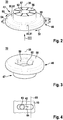
- Fig. 2 shows the holding head 33 for the in Fig. 1 shown holding device 31 of the rail foot holder 2 in a three-dimensional representation.
- the holding head 34 can be configured in accordance with the holding head 33.
- the holding head 33 has a hollow cylindrical spacer part 47 and a plate-shaped holding part 48.
- Fastening areas 49, 50 are configured on the holding part 48 of the holding head 33.
- the fastening areas 49, 50 are formed here on one side 51 of the holding part 48 of the holding head 33 which, in the assembled state, faces the contact plane 17. In a modified embodiment, only one fastening area 49 can be provided.
- the fastening area 49 extends in a direction of rotation 52 about the axis of rotation 35.
- the further fastening area 50 extends in a further direction of rotation 53 about the axis of rotation 35.
- the direction of rotation 52 and the further direction of rotation 53 are oriented relative to one another.
- the plate-shaped holding part 48 In an area 54 where the two fastening areas 49, 50 meet, the plate-shaped holding part 48 has a minimum thickness d. In an area 55, which lies opposite the area 54 with respect to the axis of rotation 35 and in which the fastening areas 49, 50 also meet, the plate-shaped holding part 48 has its maximum thickness D.
- the maximum thickness D results from the minimum thickness d plus one Slope s.
- the slope s results from a rotation in the direction of rotation 52 or the further direction of rotation 53 of 180 °.
- the holding head 33 is designed with a slope s opposite to the direction of rotation 52 or opposite to the further direction of rotation 53.
- the holding head 33 is initially oriented at least approximately with respect to its axis of rotation 35 such that the first side part 21 is located between the area 54 of the side 51 of the holding head 33 and the contact plane 17.
- the fitter can then rotate the holding head 33 about its axis of rotation 35, which reduces a holding dimension H, as can also be seen from FIG Fig. 5 is described.
- the Fitter set to no direction of rotation. That is to say, it can optionally achieve a fastening in the direction of rotation 52 or in the further direction of rotation 53.
- the holding head 33 has an end face 56 facing the contact plane 17 or the end face 17 ′ of the contact body 10.
- the end face 56 of the holding head 33 provided on the spacer 47 is urged against the contact body 10 in such a way that the holding head 33 is fixed against rotation about the axis of rotation 35 and, in this exemplary embodiment, against displacement along the second direction 42.
- the fastening force is here via the fastening means 37, 38 ( Fig. 1 ) applied.
- the end face 56 is designed as a structured end face 56.
- grooves 57 are formed on the end face 56 of the holding head 33 in this regard, of which only the groove 57 is identified to simplify the illustration.
- the groove 57 runs radially with respect to the axis of rotation 35 of the holding device 31.
- the end face 56 is otherwise designed such that the axis of rotation 35 is oriented perpendicular to the end face 56.
- Other structural elements, in particular depressions, can optionally also be configured in the end face 56.
- the grooves 57 are a possible design variant for depressions 57. Structuring the end face 56 has the advantage that dirt, liquids, such as oil, and the like have a reduced influence on the fixing of the holding head 33 on the contact body 10. In addition, the depressions 57 have the effect that the end face 56 digs into the contact plane 17 when the fastening means 37, 38 are tightened. The holding head 33 is thereby secured against rotation.
- Fig. 3 shows the in Fig. 2 shown holding head 33 from the viewing direction marked III.
- the plate-shaped holding part 48 has an end face 58 facing away from the contact plane 17 or the end face 17 ′ of the contact body 10.
- a receptacle 59 for a head 60 of the fastening means 37 extends from the end face 58.
- the receptacle 59 is not designed to be rotationally symmetrical with respect to the axis of rotation 35.
- the head 60 which is likewise not rotationally symmetrical, fits into the receptacle 59 in such a way that, in the assembled state, the holding head 33 and the fastening means 37 are rotationally fixed relative to one another.
- a depth of the receptacle 59 is less than a corresponding height of the head 61, 60 of the fastening means 37.
- the holding head 33 has an axial through-hole 62 through which a bolt (bolt section) 63 ( Fig. 4 ) of the fastening means 37 extends.
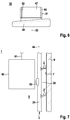
- FIG. 4 shows an excerpt, schematic representation of the contact body 10 and the bolt 63 of the first holding device 31 in an excerpt, sectional representation corresponding to a possible embodiment of the in FIG Fig. 1
- the rail foot holder 2 shown.
- the bolt 63 or bolt section 63 is guided in the second direction 42 in an elongated hole 64 of the contact body 10 so as to be movable.
- a broken line 65 illustrates a possible target position for a stop of the bolt 63 on the first side part 21 of the rail foot 20 in the assembled state. Since the line 65 shown interrupted intersects through the elongated hole 64, a certain tolerance compensation with regard to the design of the rail foot 20 is made possible.
- Fig. 5 shows in several diagrams a possible assembly sequence in which the in Fig. 1
- the rail foot holder 2 shown can be used to fasten the rail 3 in an elevator shaft, to explain a method according to an exemplary embodiment of the invention and to explain the mode of operation of the rail foot holder 2.
- the individual diagrams here show steps S1, S2, S3, S4, which occur during such an assembly can be carried out.
- step S1 the holding device 31 is first adjusted to the first side part 21 of the rail foot 20. This is also the one in the Fig. 4 line 65 shown in broken lines is illustrated in its position, the relevant stop 66 now being implemented on the first side part 21 by a side 66 ′ of the first side part 21.
- the holding device 31 strikes the stop 66 with its hollow cylindrical spacer part 47, then between the area 54 on the side 51 of the Holding part 48 and the contact plane 17 or the end face 17 'of the contact body 10 initially the maximum possible holding dimension H as the initial holding dimension H for the assembly.
- the holding dimension H between the area 54 and the contact plane 17 is preferably specified in such a way that a more or less large amount of play remains for the rail foot 20 with regard to all possible, production-related tolerances of the rail foot 20. This means that the desired backlash-free, but powerless fastening is only achieved in step S2.
- step S2 the mounting head 33 is rotated by the fitter in the first direction of rotation 52 or in the further direction of rotation 53. This is graphically illustrated by a hand 67 of the fitter.
- the holding dimension H. is reduced.
- the rotation in the direction of rotation 52 or the further direction of rotation 53 takes place until a backlash-free, but force-free fastening is achieved, as shown in step S3.
- this corresponds to a rotation of the holding head 33 in FIG Direction of rotation 52.
- the area 55 moves closer to the stop 66 or closer to the line 65 shown in broken lines.
- part of the available slope s has been used to reduce the holding dimension H to the desired value.
- step S4 the holding head 33 is then fixed relative to the contact body 10.
- the head 60 of the fastening means 37 is fixed by the fitter with a suitable tool 68 or with the hand 67.
- a nut 69 ( Fig. 8 ) of the holding device 38 are tightened.
- the rail foot holder 2 According to the exemplary embodiment, an adjustment, in particular an adjustment of the holding dimension H, with respect to the rail foot 20 is possible without dismantling.
- the rail foot 20 can be fastened in the elevator shaft 8 by means of the rail foot holder 2 without dismantling.
- the rail foot holder 2 can already be correspondingly preassembled upon delivery, so that in particular the holding devices 31, 32 are already in the preassembled state on the contact body 10. It is then not necessary to dismantle the holding devices 31, 32 for setting and / or fastening.
- Another holding dimension H ' can be adjusted in a corresponding manner on the holding head 34 of the second holding device 32.
- FIG Fig. 1 the further holding dimension H 'in relation to the second side part 22 of the rail foot 20 is shown in FIG Fig. 1 illustrated.
- this does not exclude the possibility that the rail foot holder 2 can only be assembled during assembly, that is, after delivery to the assembly site.
- step S3 and the fastening in step S4 there are contacts 75, 76 between the rail foot 20 and the holding head 33 of the first holding device 31.
- the contact 75 is here between the first side part 21 in the area of its stop 66 or its side 66 ' and the hollow cylinder-shaped spacer part 47.
- the contact 76 results between the fastening area 50 or the fastening area 49 and an upper side 27 of the rail foot 20 which faces away from its lower side 23.
- a sliding surface 77 is preferably provided on the hollow cylindrical spacer part 47 in order to avoid static friction on the contact 75 when the rail foot 20 is displaced relative to the building, in particular the wall 9.
- a suitable lubricant can be attached to the sliding surface 77.
- the fastening areas 49, 50 are preferably made as smooth as possible.
- the sliding surface 77 and / or the fastening areas 49, 50 are formed on or with a friction-reducing coating.
- Fig. 6 shows the in Fig. 2 shown holding head 33 according to a further embodiment.
- a sliding ring 80 is mounted on the hollow cylindrical spacer part 47 of the holding head 33.
- Contact 75 ( Fig. 5 ) then comes about between an outer side 81 of the sliding ring 80 and the side 66 'of the first side part 21 of the rail foot 20.
- the sliding ring 80 can rotate about the axis of rotation 35 relative to the holding head 33.
- the bearing 82 of the sliding ring 80 designed here as a sliding bearing 82 on the hollow cylindrical spacer 47, can be lubricated by a suitable lubricant.
- Fig. 7 shows the elevator installation 1, in which the rail 3 with the in Fig. 1 shown rail foot holder 2 and a further rail foot holder 2 'in the elevator shaft 8 is attached, in an excerpt, schematic representation.
- the elevator installation 1 here has an elevator cage 90 which is suspended from a suspension element 91.
- a guide roller 92 is shown by way of example, by means of which the elevator car 90 is guided on the rail 3.
- the guide roller 92 interacts with the rail head 24 of the rail 3. Managers act essentially in or against the second direction 42.
- the rail 3 is reliably fixed via the holding heads 33, 34.
- the rail 3 is also held reliably on the wall 9 or the wall 7 of the elevator shaft 8.
- Fig. 8 shows the in Fig. 1 shown rail foot holder 2 and the rail 3 in an excerpt from the viewing direction designated VIII.
- the nut 70 for the bolt 71, in particular screw bolt 71, of the second holding device 32 is shown here.
- the screw bolt 71 here has the head 61.
- the nut 70 is in step S4 ( Fig. 5 ) tightened while the head 61 and thus the holding head 34 is held in its position.
- Another nut 69 which is designed like the nut 70, is used for the bolt 63, in particular screw bolt 63, only one nut 69, 70 being shown by way of example to simplify the illustration. Further elements can be used here, in particular a washer 72.
Landscapes
- Lift-Guide Devices, And Elevator Ropes And Cables (AREA)
- Chairs For Special Purposes, Such As Reclining Chairs (AREA)
Claims (14)
- Support de patin de rail (2), qui sert à fixer un rail (3) d'une installation d'ascenseur (1) dans une gaine d'ascenseur (8), pourvu d'un corps d'appui (10), qui peut se placer dans la gaine d'ascenseur (8) et d'au moins un système de retenue (31), le corps d'appui (10) prédéfinissant un plan d'appui (17) pour un patin de rail (20) du rail (3), le système de retenue (31) comportant une tête de retenue (33), pour la fixation du rail (3), une première partie latérale (21) du patin de rail (20) pouvant se placer entre la tête de retenue (33) du système de retenue (31) et le plan d'appui (17) et lors de la fixation du rail (3), une dimension de retenue (H) entre la tête de retenue (33) du système de retenue (31) et le plan d'appui (17) étant variable pour compenser des tolérances de la première partie latérale (21) du patin de rail (20),
pour réduire la dimension de retenue (H), la tête de retenue (33) du système de retenue (31) étant rotative dans une position de fixation, dans un sens de rotation (52) autour d'un axe de rotation (35) du système de retenue (31), caractérisé en ce que dans au moins une zone de fixation (49) s'étendant dans le sens de rotation (52) autour de l'axe de rotation (35) du système de retenue (31) sur laquelle au moins un contact (76) indirect est possible entre la tête de retenue (33) du système de retenue (31) et la première partie latérale (21) du patin de rail (20), une face (51) de la tête de retenue (33) du système de retenue (31) dirigée vers le plan d'appui (17) est conçue avec une inclinaison (s) à l'encontre du sens de rotation (52). - Support de patin de rail selon la revendication 1,
caractérisé en ce que
lors d'un réglage servant à réduire la dimension de retenue (H), la tête de retenue (33) est rotative dans une position de fixation autour d'un axe de rotation (35) dans un autre sens de rotation (53) orienté à l'encontre du sens de rotation (52), et en ce que dans une autre zone de fixation (50) s'étendant dans l'autre sens de rotation (53) autour de l'axe de rotation (35), dans laquelle au moins un contact (76) indirect entre la tête de retenue (33) et la première partie latérale (21) du patin de rail (20) est possible, la face (51) de la tête de retenue (33) dirigée vers le plan d'appui (17) est conçue avec une inclinaison (s) à l'encontre de l'autre sens de rotation (53). - Support de patin de rail selon la revendication 1 ou 2,
caractérisé en ce que
le système de retenue (31) est ajustable par rapport au corps d'appui (10), de telle sorte qu'un écart entre l'axe de rotation (35) du système de retenue (31) et un autre système de retenue (32), entre lesquels le patin de rail (20) soit se fixer est variable. - Support de patin de rail selon la revendication 3,
caractérisé en ce que
le corps d'appui (10) comporte un trou oblong (64) dans lequel est guidé un boulon (63) du système de retenue (31). - Support de patin de rail selon l'une quelconque des revendications 1 à 4,
caractérisé en ce que
la tête de retenue (33) du système de retenue (31) comporte une face frontale (56) dirigée vers le corps d'appui (10), qui pour la fixation de la tête de retenue (33) par rapport au corps d'appui (10) peut être soumise contre le corps d'appui (10) à l'aide d'un moyen de fixation (37) du système de retenue (31). - Support de patin de rail selon la revendication 5,
caractérisé en ce que
la face frontale (56) de la tête de retenue (33) du système de retenue (31) qui est dirigée vers le corps d'appui (10) est conçue sous la forme d'une face frontale (56) structurée et/ou en ce que la face frontale (56) de la tête de retenue (33) du système de retenue (31) qui est dirigée vers le corps d'appui (10) comporte des cannelures s'écoulant en direction radiale de l'axe de rotation (35) du système de retenue (31). - Support de patin de rail selon l'une quelconque des revendications 3 à 6,
caractérisé en ce que
l'autre système de retenue (31), respectivement un axe de rotation (36) de l'autre système de retenue (31) est placé sur le corps d'appui (10). - Support de patin de rail selon l'une quelconque des revendications 3 à 7,
caractérisé en ce que
l'autre système de retenue (32) est prévu, qui comporte une tête de retenue (34), en ce que pour la fixation du rail (3), une deuxième partie latérale (22) du patin de rail (20) peut se placer entre la tête de retenue (34) de l'autre système de retenue (32) et le plan d'appui (17), en ce que pour la fixation du rail (3), une autre dimension de retenue (H') entre la tête de retenue (34) de l'autre système de retenue (32) et le plan d'appui (17) est variable, pour compenser des tolérances de la deuxième partie latérale (22) du patin de rail (20), en ce que lors d'un réglage servant à réduire l'autre dimension de retenue (H'), la tête de retenue (34) de l'autre système de retenue (32) est rotative dans une position de fixation, dans un sens de rotation autour d'un axe de rotation (36) de l'autre système de retenue (32) et en ce que dans au moins une zone de fixation s'étendant dans le sens de rotation autour de l'axe de rotation (36) de l'autre système de retenue (32), sur laquelle au moins un contact indirect est possible entre la tête de retenue (34) de l'autre système de retenue (32) et la deuxième partie latérale (22) du patin de rail (20), une face de la tête de retenue (34) de l'autre système de retenue (32) qui est dirigée vers le plan d'appui (17) est conçue avec une inclinaison (s) à l'encontre du sens de rotation. - Support de patin de rail selon l'une quelconque des revendications 1 à 8,
caractérisé en ce que
sur la face (51) qui est dirigée vers le plan d'appui (17), dans l'au moins une zone de fixation (49, 50), la tête de retenue (33), respectivement l'autre tête de retenue (34) est conçue avec une inclinaison (s) s'écoulant en continu dans le sens de rotation (52), respectivement dans l'autre sens de rotation (53). - Support de patin de rail selon l'une quelconque des revendications 1 à 9,
caractérisé
en ce qu'il est prévu un corps de fixation (4), qui peut se fixer dans la gaine d'ascenseur (8) et en ce que le corps d'appui (10) peut se relier avec le corps de fixation (4) dans plusieurs positions de fixation possibles. - Support de patin de rail selon l'une quelconque des revendications 1 à 10,
caractérisé en ce que
sur la tête de retenue (33), respectivement sur l'autre tête de retenue (34) est prévue au moins une surface de glissement (77). - Support de patin de rail selon la revendication 11,
caractérisé en ce que
sur la surface de glissement (77), pour le guidage du patin de rail (20), un contact (75) est possible entre la première partie latérale (21), respectivement la deuxième partie latérale (22) du patin de rail (20) et la tête de retenue (33, 34) lorsque le rail (3) est fixé, et/ou en ce que la surface de glissement (77) est conçue sur un revêtement réducteur de friction de la tête de retenue (33), respectivement de l'autre tête de retenue (34) ou en ce que sur la tête de retenue (33), respectivement sur l'autre tête de retenue (34) est logée une bague coulissante (80). - Procédé, destiné à fixer un rail (3) d'une installation d'ascenseur (1) dans une gaine d'ascenseur (8) au moyen d'au moins un support de patin de rail (2) selon l'une quelconque des revendications 1 à 12, lors duquel on place le corps d'appui (10) dans la gaine d'ascenseur (8), lors duquel on place une première partie latérale (21) du patin de rail (20) entre la tête de retenue (33) du système de retenue (31) et le plan d'appui (17) prédéfini par le corps d'appui (10) et lors duquel, pour réduire la dimension de retenue (H) entre la tête de retenue (33) du système de retenue (31) et le plan d'appui (17), on fait tourner la tête de retenue (33) autour de l'axe de rotation (35) du système de retenue (31).
- Procédé selon la revendication 13,
caractérisé en ce que
pour réduire la dimension de retenue (H) entre la tête de retenue (33) du système de retenue (31) et le plan d'appui (17), on fait tourner la tête de retenue (33) du système de retenue (31) autour de l'axe de rotation (35) du système de retenue (31) jusqu'à ce que la première partie latérale (21) du patin de rail (20) soit retenue sensiblement sans jeu, mais avec une force de retenue pratiquement infime entre la tête de retenue (33) du système de retenue (31) et le plan d'appui (17).
Applications Claiming Priority (2)
| Application Number | Priority Date | Filing Date | Title |
|---|---|---|---|
| EP16202634 | 2016-12-07 | ||
| PCT/EP2017/081795 WO2018104435A1 (fr) | 2016-12-07 | 2017-12-07 | Support de patin de rail pour fixer un rail d'une installation d'ascenseur |
Publications (2)
| Publication Number | Publication Date |
|---|---|
| EP3551565A1 EP3551565A1 (fr) | 2019-10-16 |
| EP3551565B1 true EP3551565B1 (fr) | 2021-02-03 |
Family
ID=57517786
Family Applications (1)
| Application Number | Title | Priority Date | Filing Date |
|---|---|---|---|
| EP17828848.6A Active EP3551565B1 (fr) | 2016-12-07 | 2017-12-07 | Support de pieds sur rails pour fixer un rail d'ascenseur |
Country Status (4)
| Country | Link |
|---|---|
| US (1) | US10906779B2 (fr) |
| EP (1) | EP3551565B1 (fr) |
| CN (1) | CN110023226B (fr) |
| WO (1) | WO2018104435A1 (fr) |
Families Citing this family (8)
| Publication number | Priority date | Publication date | Assignee | Title |
|---|---|---|---|---|
| DE102015217262A1 (de) * | 2015-09-10 | 2017-03-16 | Thyssenkrupp Ag | Führungsschiene für eine Aufzugsanlage |
| WO2018104435A1 (fr) * | 2016-12-07 | 2018-06-14 | Inventio Ag | Support de patin de rail pour fixer un rail d'une installation d'ascenseur |
| WO2018104157A1 (fr) * | 2016-12-07 | 2018-06-14 | Inventio Ag | Support de patin de rail pour fixer un rail d'une installation d'ascenseur |
| US10906778B2 (en) * | 2017-08-21 | 2021-02-02 | Brian K. Keller | Elevator rail clamping system |
| CN112079226B (zh) * | 2020-09-14 | 2026-05-19 | 杭州西奥电梯有限公司 | 电梯部件的固定结构及电梯导轨支架 |
| CN119317589A (zh) * | 2022-06-08 | 2025-01-14 | 因温特奥股份公司 | 电梯系统 |
| CN119212940A (zh) * | 2022-06-16 | 2024-12-27 | 株式会社日立制作所 | 电梯设备 |
| USD1113418S1 (en) * | 2022-09-02 | 2026-02-17 | Inpro Corporation | Elevator mount |
Family Cites Families (14)
| Publication number | Priority date | Publication date | Assignee | Title |
|---|---|---|---|---|
| US3420337A (en) * | 1967-09-21 | 1969-01-07 | John E Magee | Rail fastener |
| DE3010826A1 (de) * | 1980-03-21 | 1981-10-01 | M.A.N. Maschinenfabrik Augsburg-Nürnberg AG, 8500 Nürnberg | Gleitende schienenbefestigung fuer aufzugsfuehrungsschienen |
| US4431087A (en) * | 1981-05-29 | 1984-02-14 | Westinghouse Electric Corp. | Guide rail clamping method and assembly |
| US4577729A (en) * | 1984-12-05 | 1986-03-25 | Westinghouse Electric Corp. | Guide rail clamping assembly |
| CH680786A5 (fr) | 1990-03-26 | 1992-11-13 | Inventio Ag | |
| US6413005B1 (en) * | 1999-03-23 | 2002-07-02 | Wahoo Concrete Products, Inc. | Fastener having a self-centering and self-aligning capability for one-sided insertion and tightening on a slat floor |
| WO2003011736A1 (fr) * | 2001-07-30 | 2003-02-13 | Inventio Ag | Procede et dispositif de fixation d'un rail de guidage |
| US7752978B2 (en) * | 2007-11-21 | 2010-07-13 | Pacifiic Bearing Company | Multifaceted guide rail, guide assembly and method of forming guide assemblies |
| BRPI0925060A2 (pt) * | 2009-04-02 | 2015-07-28 | De Vera Savera Sa | Sistema de união com autoalinhamento, para guias de elevador |
| US20120133164A1 (en) * | 2010-11-29 | 2012-05-31 | S.A. De Vera (Savera) | Adjustment flange for lift guides |
| ES2421083B1 (es) | 2012-02-22 | 2014-11-04 | S.A. De Vera (Savera) | Sistema de brida adaptable, para guías de ascensor |
| PL3390260T3 (pl) * | 2015-12-17 | 2021-02-08 | Inventio Ag | Moduł mocujący do mocowania szyn windy |
| EP3231757B1 (fr) * | 2016-04-15 | 2020-04-08 | Otis Elevator Company | Support de rail de guidage |
| WO2018104435A1 (fr) * | 2016-12-07 | 2018-06-14 | Inventio Ag | Support de patin de rail pour fixer un rail d'une installation d'ascenseur |
-
2017
- 2017-12-07 WO PCT/EP2017/081795 patent/WO2018104435A1/fr not_active Ceased
- 2017-12-07 EP EP17828848.6A patent/EP3551565B1/fr active Active
- 2017-12-07 CN CN201780074260.5A patent/CN110023226B/zh active Active
- 2017-12-07 US US16/466,654 patent/US10906779B2/en not_active Expired - Fee Related
Non-Patent Citations (1)
| Title |
|---|
| None * |
Also Published As
| Publication number | Publication date |
|---|---|
| CN110023226B (zh) | 2021-02-05 |
| EP3551565A1 (fr) | 2019-10-16 |
| US10906779B2 (en) | 2021-02-02 |
| WO2018104435A1 (fr) | 2018-06-14 |
| CN110023226A (zh) | 2019-07-16 |
| US20200062547A1 (en) | 2020-02-27 |
Similar Documents
| Publication | Publication Date | Title |
|---|---|---|
| WO2018104435A1 (fr) | Support de patin de rail pour fixer un rail d'une installation d'ascenseur | |
| EP2720907B1 (fr) | Dispositif de fixation comprenant un compensateur de tolérance | |
| EP1696138B1 (fr) | Dispositif de compensation de tolérance | |
| EP3036443B1 (fr) | Procédé pour assembler des pièces et module correspondant | |
| EP0886071A1 (fr) | Ensemble de vis | |
| EP3586018B1 (fr) | Dispositif de fixation et module de fixation | |
| EP4035834B1 (fr) | Agencement constitué d'un dispositif de serrage pour une liaison vissée, ainsi que d'un dispositif de sécurité | |
| EP2532568A2 (fr) | Dispositif de fixation d'un composant, par exemple d'une rambarde, sur une carrosserie de véhicule | |
| WO2020193186A2 (fr) | Dispositif d'alignement et procédé d'alignement d'un rail de guidage d'une installation d'ascenseur | |
| DE102016209846A1 (de) | Keilsicherungsmutteranordnung | |
| EP2816169B1 (fr) | Procédé de liaison de deux barres disposées de manière excentrique l'une par rapport à l'autre et dispositif de liaison de deux composants dotés respectivement d'une barre | |
| DE2905795A1 (de) | Betonbrueckentraeger-auflageraufbau und dessen anwendung in einem verfahren zum freitragenden errichten eines betonbrueckentraegers | |
| DE20113561U1 (de) | Werkzeug zum Ein- und Ausbauen von Lagerelementen | |
| EP2812534B1 (fr) | Outil de pose et procédé de montage d'une tige d'ancrage | |
| DE1816880A1 (de) | Befestigungsvorrichtung mit automatischer Begrenzung des aufgebrachten Drehmoments | |
| EP4405591B1 (fr) | Système et procédé pour fixer des panneaux de facade | |
| EP1903219B1 (fr) | Dispositif pour la fixation d'un composant sur un élément de support | |
| EP3348742B1 (fr) | Dispositif destiné à supporter une plaque de façade sur une structure portante | |
| DE102021105969B3 (de) | Nivellierschuh und Verfahren zum Montieren eines Nivellierschuhs | |
| WO2018104157A1 (fr) | Support de patin de rail pour fixer un rail d'une installation d'ascenseur | |
| EP2604868B1 (fr) | Dispositif et procédé destinés à la liaison de composants | |
| DE102018202442B3 (de) | Schraubwerkzeug zum Justieren von Anbauteilen sowie ein korrespondierendes Verfahren zum Justieren eines Anbauteils | |
| EP1710193B1 (fr) | Dispositif de fixation pour les rails de guidages d'ascenseurs | |
| DE10123266A1 (de) | Aufspannplatte für eine Spannvorrichtung mit Einzugnippel | |
| DE102024116548A1 (de) | Montagevorrichtung für ein Sanitärbecken sowie Verfahren zum Bereitstellen eines Sanitärbeckens |
Legal Events
| Date | Code | Title | Description |
|---|---|---|---|
| STAA | Information on the status of an ep patent application or granted ep patent |
Free format text: STATUS: UNKNOWN |
|
| STAA | Information on the status of an ep patent application or granted ep patent |
Free format text: STATUS: THE INTERNATIONAL PUBLICATION HAS BEEN MADE |
|
| PUAI | Public reference made under article 153(3) epc to a published international application that has entered the european phase |
Free format text: ORIGINAL CODE: 0009012 |
|
| STAA | Information on the status of an ep patent application or granted ep patent |
Free format text: STATUS: REQUEST FOR EXAMINATION WAS MADE |
|
| 17P | Request for examination filed |
Effective date: 20190502 |
|
| AK | Designated contracting states |
Kind code of ref document: A1 Designated state(s): AL AT BE BG CH CY CZ DE DK EE ES FI FR GB GR HR HU IE IS IT LI LT LU LV MC MK MT NL NO PL PT RO RS SE SI SK SM TR |
|
| AX | Request for extension of the european patent |
Extension state: BA ME |
|
| DAV | Request for validation of the european patent (deleted) | ||
| DAX | Request for extension of the european patent (deleted) | ||
| GRAP | Despatch of communication of intention to grant a patent |
Free format text: ORIGINAL CODE: EPIDOSNIGR1 |
|
| STAA | Information on the status of an ep patent application or granted ep patent |
Free format text: STATUS: GRANT OF PATENT IS INTENDED |
|
| INTG | Intention to grant announced |
Effective date: 20200715 |
|
| GRAS | Grant fee paid |
Free format text: ORIGINAL CODE: EPIDOSNIGR3 |
|
| GRAA | (expected) grant |
Free format text: ORIGINAL CODE: 0009210 |
|
| STAA | Information on the status of an ep patent application or granted ep patent |
Free format text: STATUS: THE PATENT HAS BEEN GRANTED |
|
| AK | Designated contracting states |
Kind code of ref document: B1 Designated state(s): AL AT BE BG CH CY CZ DE DK EE ES FI FR GB GR HR HU IE IS IT LI LT LU LV MC MK MT NL NO PL PT RO RS SE SI SK SM TR |
|
| REG | Reference to a national code |
Ref country code: GB Ref legal event code: FG4D Free format text: NOT ENGLISH |
|
| REG | Reference to a national code |
Ref country code: AT Ref legal event code: REF Ref document number: 1359665 Country of ref document: AT Kind code of ref document: T Effective date: 20210215 Ref country code: CH Ref legal event code: EP |
|
| REG | Reference to a national code |
Ref country code: DE Ref legal event code: R096 Ref document number: 502017009295 Country of ref document: DE |
|
| REG | Reference to a national code |
Ref country code: IE Ref legal event code: FG4D Free format text: LANGUAGE OF EP DOCUMENT: GERMAN |
|
| REG | Reference to a national code |
Ref country code: NL Ref legal event code: MP Effective date: 20210203 |
|
| REG | Reference to a national code |
Ref country code: LT Ref legal event code: MG9D |
|
| PG25 | Lapsed in a contracting state [announced via postgrant information from national office to epo] |
Ref country code: FI Free format text: LAPSE BECAUSE OF FAILURE TO SUBMIT A TRANSLATION OF THE DESCRIPTION OR TO PAY THE FEE WITHIN THE PRESCRIBED TIME-LIMIT Effective date: 20210203 Ref country code: GR Free format text: LAPSE BECAUSE OF FAILURE TO SUBMIT A TRANSLATION OF THE DESCRIPTION OR TO PAY THE FEE WITHIN THE PRESCRIBED TIME-LIMIT Effective date: 20210504 Ref country code: HR Free format text: LAPSE BECAUSE OF FAILURE TO SUBMIT A TRANSLATION OF THE DESCRIPTION OR TO PAY THE FEE WITHIN THE PRESCRIBED TIME-LIMIT Effective date: 20210203 Ref country code: NO Free format text: LAPSE BECAUSE OF FAILURE TO SUBMIT A TRANSLATION OF THE DESCRIPTION OR TO PAY THE FEE WITHIN THE PRESCRIBED TIME-LIMIT Effective date: 20210503 Ref country code: PT Free format text: LAPSE BECAUSE OF FAILURE TO SUBMIT A TRANSLATION OF THE DESCRIPTION OR TO PAY THE FEE WITHIN THE PRESCRIBED TIME-LIMIT Effective date: 20210604 Ref country code: BG Free format text: LAPSE BECAUSE OF FAILURE TO SUBMIT A TRANSLATION OF THE DESCRIPTION OR TO PAY THE FEE WITHIN THE PRESCRIBED TIME-LIMIT Effective date: 20210503 Ref country code: LT Free format text: LAPSE BECAUSE OF FAILURE TO SUBMIT A TRANSLATION OF THE DESCRIPTION OR TO PAY THE FEE WITHIN THE PRESCRIBED TIME-LIMIT Effective date: 20210203 |
|
| PG25 | Lapsed in a contracting state [announced via postgrant information from national office to epo] |
Ref country code: SE Free format text: LAPSE BECAUSE OF FAILURE TO SUBMIT A TRANSLATION OF THE DESCRIPTION OR TO PAY THE FEE WITHIN THE PRESCRIBED TIME-LIMIT Effective date: 20210203 Ref country code: PL Free format text: LAPSE BECAUSE OF FAILURE TO SUBMIT A TRANSLATION OF THE DESCRIPTION OR TO PAY THE FEE WITHIN THE PRESCRIBED TIME-LIMIT Effective date: 20210203 Ref country code: LV Free format text: LAPSE BECAUSE OF FAILURE TO SUBMIT A TRANSLATION OF THE DESCRIPTION OR TO PAY THE FEE WITHIN THE PRESCRIBED TIME-LIMIT Effective date: 20210203 Ref country code: RS Free format text: LAPSE BECAUSE OF FAILURE TO SUBMIT A TRANSLATION OF THE DESCRIPTION OR TO PAY THE FEE WITHIN THE PRESCRIBED TIME-LIMIT Effective date: 20210203 Ref country code: NL Free format text: LAPSE BECAUSE OF FAILURE TO SUBMIT A TRANSLATION OF THE DESCRIPTION OR TO PAY THE FEE WITHIN THE PRESCRIBED TIME-LIMIT Effective date: 20210203 |
|
| PG25 | Lapsed in a contracting state [announced via postgrant information from national office to epo] |
Ref country code: IS Free format text: LAPSE BECAUSE OF FAILURE TO SUBMIT A TRANSLATION OF THE DESCRIPTION OR TO PAY THE FEE WITHIN THE PRESCRIBED TIME-LIMIT Effective date: 20210603 |
|
| PG25 | Lapsed in a contracting state [announced via postgrant information from national office to epo] |
Ref country code: CZ Free format text: LAPSE BECAUSE OF FAILURE TO SUBMIT A TRANSLATION OF THE DESCRIPTION OR TO PAY THE FEE WITHIN THE PRESCRIBED TIME-LIMIT Effective date: 20210203 Ref country code: EE Free format text: LAPSE BECAUSE OF FAILURE TO SUBMIT A TRANSLATION OF THE DESCRIPTION OR TO PAY THE FEE WITHIN THE PRESCRIBED TIME-LIMIT Effective date: 20210203 Ref country code: SM Free format text: LAPSE BECAUSE OF FAILURE TO SUBMIT A TRANSLATION OF THE DESCRIPTION OR TO PAY THE FEE WITHIN THE PRESCRIBED TIME-LIMIT Effective date: 20210203 |
|
| REG | Reference to a national code |
Ref country code: DE Ref legal event code: R097 Ref document number: 502017009295 Country of ref document: DE |
|
| PG25 | Lapsed in a contracting state [announced via postgrant information from national office to epo] |
Ref country code: SK Free format text: LAPSE BECAUSE OF FAILURE TO SUBMIT A TRANSLATION OF THE DESCRIPTION OR TO PAY THE FEE WITHIN THE PRESCRIBED TIME-LIMIT Effective date: 20210203 Ref country code: DK Free format text: LAPSE BECAUSE OF FAILURE TO SUBMIT A TRANSLATION OF THE DESCRIPTION OR TO PAY THE FEE WITHIN THE PRESCRIBED TIME-LIMIT Effective date: 20210203 Ref country code: RO Free format text: LAPSE BECAUSE OF FAILURE TO SUBMIT A TRANSLATION OF THE DESCRIPTION OR TO PAY THE FEE WITHIN THE PRESCRIBED TIME-LIMIT Effective date: 20210203 |
|
| PLBE | No opposition filed within time limit |
Free format text: ORIGINAL CODE: 0009261 |
|
| STAA | Information on the status of an ep patent application or granted ep patent |
Free format text: STATUS: NO OPPOSITION FILED WITHIN TIME LIMIT |
|
| 26N | No opposition filed |
Effective date: 20211104 |
|
| PG25 | Lapsed in a contracting state [announced via postgrant information from national office to epo] |
Ref country code: ES Free format text: LAPSE BECAUSE OF FAILURE TO SUBMIT A TRANSLATION OF THE DESCRIPTION OR TO PAY THE FEE WITHIN THE PRESCRIBED TIME-LIMIT Effective date: 20210203 Ref country code: AL Free format text: LAPSE BECAUSE OF FAILURE TO SUBMIT A TRANSLATION OF THE DESCRIPTION OR TO PAY THE FEE WITHIN THE PRESCRIBED TIME-LIMIT Effective date: 20210203 |
|
| PG25 | Lapsed in a contracting state [announced via postgrant information from national office to epo] |
Ref country code: SI Free format text: LAPSE BECAUSE OF FAILURE TO SUBMIT A TRANSLATION OF THE DESCRIPTION OR TO PAY THE FEE WITHIN THE PRESCRIBED TIME-LIMIT Effective date: 20210203 |
|
| PG25 | Lapsed in a contracting state [announced via postgrant information from national office to epo] |
Ref country code: IT Free format text: LAPSE BECAUSE OF FAILURE TO SUBMIT A TRANSLATION OF THE DESCRIPTION OR TO PAY THE FEE WITHIN THE PRESCRIBED TIME-LIMIT Effective date: 20210203 |
|
| PG25 | Lapsed in a contracting state [announced via postgrant information from national office to epo] |
Ref country code: IS Free format text: LAPSE BECAUSE OF FAILURE TO SUBMIT A TRANSLATION OF THE DESCRIPTION OR TO PAY THE FEE WITHIN THE PRESCRIBED TIME-LIMIT Effective date: 20210603 |
|
| PG25 | Lapsed in a contracting state [announced via postgrant information from national office to epo] |
Ref country code: MC Free format text: LAPSE BECAUSE OF FAILURE TO SUBMIT A TRANSLATION OF THE DESCRIPTION OR TO PAY THE FEE WITHIN THE PRESCRIBED TIME-LIMIT Effective date: 20210203 |
|
| REG | Reference to a national code |
Ref country code: BE Ref legal event code: MM Effective date: 20211231 |
|
| PG25 | Lapsed in a contracting state [announced via postgrant information from national office to epo] |
Ref country code: LU Free format text: LAPSE BECAUSE OF NON-PAYMENT OF DUE FEES Effective date: 20211207 Ref country code: IE Free format text: LAPSE BECAUSE OF NON-PAYMENT OF DUE FEES Effective date: 20211207 |
|
| PG25 | Lapsed in a contracting state [announced via postgrant information from national office to epo] |
Ref country code: BE Free format text: LAPSE BECAUSE OF NON-PAYMENT OF DUE FEES Effective date: 20211231 |
|
| PG25 | Lapsed in a contracting state [announced via postgrant information from national office to epo] |
Ref country code: CY Free format text: LAPSE BECAUSE OF FAILURE TO SUBMIT A TRANSLATION OF THE DESCRIPTION OR TO PAY THE FEE WITHIN THE PRESCRIBED TIME-LIMIT Effective date: 20210203 |
|
| PG25 | Lapsed in a contracting state [announced via postgrant information from national office to epo] |
Ref country code: HU Free format text: LAPSE BECAUSE OF FAILURE TO SUBMIT A TRANSLATION OF THE DESCRIPTION OR TO PAY THE FEE WITHIN THE PRESCRIBED TIME-LIMIT; INVALID AB INITIO Effective date: 20171207 |
|
| REG | Reference to a national code |
Ref country code: AT Ref legal event code: MM01 Ref document number: 1359665 Country of ref document: AT Kind code of ref document: T Effective date: 20221207 |
|
| PG25 | Lapsed in a contracting state [announced via postgrant information from national office to epo] |
Ref country code: AT Free format text: LAPSE BECAUSE OF NON-PAYMENT OF DUE FEES Effective date: 20221207 |
|
| PG25 | Lapsed in a contracting state [announced via postgrant information from national office to epo] |
Ref country code: MK Free format text: LAPSE BECAUSE OF FAILURE TO SUBMIT A TRANSLATION OF THE DESCRIPTION OR TO PAY THE FEE WITHIN THE PRESCRIBED TIME-LIMIT Effective date: 20210203 Ref country code: AT Free format text: LAPSE BECAUSE OF NON-PAYMENT OF DUE FEES Effective date: 20221207 |
|
| PG25 | Lapsed in a contracting state [announced via postgrant information from national office to epo] |
Ref country code: TR Free format text: LAPSE BECAUSE OF FAILURE TO SUBMIT A TRANSLATION OF THE DESCRIPTION OR TO PAY THE FEE WITHIN THE PRESCRIBED TIME-LIMIT Effective date: 20210203 |
|
| PG25 | Lapsed in a contracting state [announced via postgrant information from national office to epo] |
Ref country code: MT Free format text: LAPSE BECAUSE OF FAILURE TO SUBMIT A TRANSLATION OF THE DESCRIPTION OR TO PAY THE FEE WITHIN THE PRESCRIBED TIME-LIMIT Effective date: 20210203 |
|
| PGFP | Annual fee paid to national office [announced via postgrant information from national office to epo] |
Ref country code: GB Payment date: 20241217 Year of fee payment: 8 |
|
| PGFP | Annual fee paid to national office [announced via postgrant information from national office to epo] |
Ref country code: FR Payment date: 20241227 Year of fee payment: 8 |
|
| PGFP | Annual fee paid to national office [announced via postgrant information from national office to epo] |
Ref country code: CH Payment date: 20250101 Year of fee payment: 8 |
|
| PGFP | Annual fee paid to national office [announced via postgrant information from national office to epo] |
Ref country code: DE Payment date: 20251229 Year of fee payment: 9 |
|
| PGFP | Annual fee paid to national office [announced via postgrant information from national office to epo] |
Ref country code: AT Payment date: 20260410 Year of fee payment: 5 |
|
| REG | Reference to a national code |
Ref country code: CH Ref legal event code: H13 Free format text: ST27 STATUS EVENT CODE: U-0-0-H10-H13 (AS PROVIDED BY THE NATIONAL OFFICE) Effective date: 20260723 |