EP3551572B1 - Dispositif de fin pour machines de distribution - Google Patents
Dispositif de fin pour machines de distribution Download PDFInfo
- Publication number
- EP3551572B1 EP3551572B1 EP17823219.5A EP17823219A EP3551572B1 EP 3551572 B1 EP3551572 B1 EP 3551572B1 EP 17823219 A EP17823219 A EP 17823219A EP 3551572 B1 EP3551572 B1 EP 3551572B1
- Authority
- EP
- European Patent Office
- Prior art keywords
- fact
- regulation
- control
- interaction
- mixing
- Prior art date
- Legal status (The legal status is an assumption and is not a legal conclusion. Google has not performed a legal analysis and makes no representation as to the accuracy of the status listed.)
- Active
Links
Images

Classifications
-
- B—PERFORMING OPERATIONS; TRANSPORTING
- B67—OPENING, CLOSING OR CLEANING BOTTLES, JARS OR SIMILAR CONTAINERS; LIQUID HANDLING
- B67D—DISPENSING, DELIVERING OR TRANSFERRING LIQUIDS, NOT OTHERWISE PROVIDED FOR
- B67D1/00—Apparatus or devices for dispensing beverages on draught
- B67D1/0015—Apparatus or devices for dispensing beverages on draught the beverage being prepared by mixing at least two liquid components
- B67D1/0021—Apparatus or devices for dispensing beverages on draught the beverage being prepared by mixing at least two liquid components the components being mixed at the time of dispensing, i.e. post-mix dispensers
-
- B—PERFORMING OPERATIONS; TRANSPORTING
- B67—OPENING, CLOSING OR CLEANING BOTTLES, JARS OR SIMILAR CONTAINERS; LIQUID HANDLING
- B67D—DISPENSING, DELIVERING OR TRANSFERRING LIQUIDS, NOT OTHERWISE PROVIDED FOR
- B67D1/00—Apparatus or devices for dispensing beverages on draught
- B67D1/0042—Details of specific parts of the dispensers
- B67D1/0043—Mixing devices for liquids
-
- B—PERFORMING OPERATIONS; TRANSPORTING
- B67—OPENING, CLOSING OR CLEANING BOTTLES, JARS OR SIMILAR CONTAINERS; LIQUID HANDLING
- B67D—DISPENSING, DELIVERING OR TRANSFERRING LIQUIDS, NOT OTHERWISE PROVIDED FOR
- B67D1/00—Apparatus or devices for dispensing beverages on draught
- B67D1/08—Details
- B67D1/0878—Safety, warning or controlling devices
Definitions
- the present invention relates to an ending device for dispensing machines, in particular for machines dispensing beverages or other liquid substances.
- Machines for dispensing beverages or other liquid substances to be consumed are usually supplied with one or more ending devices adapted to control the mixing and dispensing of the beverage to be supplied to the consumer.
- An ending device according to the preamble of independent claim 1 is disclosed in US 2001/0048958 A1 .
- the ending devices have a regulation assembly comprising a first regulation element, e.g., a solenoid valve, and an inlet nozzle associated with it from which it receives water in a controlled manner.
- a first regulation element e.g., a solenoid valve
- the device furthermore, comprises a mixing body connected to a second regulation element, e.g. a peristaltic pump, for the controlled withdrawal from the container of concentrated juice or other substances useful for obtaining the finished beverage.
- a second regulation element e.g. a peristaltic pump
- the mixing body is connected to the inlet nozzle in order to receive water from the latter and mix it with the concentrated juice to obtain the drink to be consumed.
- the latter is delivered via a dispensing element connected to the mixing body.
- a delicate aspect tied to known devices concerns the connection of the inlet nozzle to the first regulation element.
- a drawback of known devices in fact, is tied to the replacement and/or maintenance operations of the inlet nozzle.
- the tap is necessarily disconnected from the solenoid valve, with the latter able to continue dispensing water.
- the main aim of the present invention is to provide an ending device for dispensing machines which allows improving the control of the substances to be delivered.
- One object of the present invention is to provide an ending device for dispensing machines which allows minimizing the waste of the substances to be delivered.
- Another object of the present invention is to provide an ending device for dispensing machines which allows facilitating the maintenance operations of the machines themselves.
- Another object of the present invention is to provide an ending device for dispensing machines which allows overcoming the aforementioned drawbacks of the prior art within the scope of a simple, rational, easy, efficient to use and cost-effective solution.
- reference numeral 1 globally indicates a device for dispensing machines.
- the device 1 comprises a regulation assembly 2 activatable for the regulation of the outflow of a liquid substance to be mixed, preferably water.
- the liquid substance can be delivered by actuating specific commands present in the dispensing machine, usually accessible by a user.
- the regulation assembly 2 comprises at least a conveying duct 3 of the liquid substance and a regulation element 4 operable for the regulation of the outflow of the liquid substance.
- the conveying duct 3 is provided with an inlet end 5, in which the water to be regulated enters, and with an outlet end 6.
- the regulation element 4 is interposed between the two ends 5, 6 so as to regulate the amount of water leaving the duct itself.
- the conveying duct 3 also comprises an auxiliary outlet end 6a, parallel to the outlet end 6.
- the auxiliary outlet end 6a has the function of allowing a manual regulation of the maximum flow rate.
- the regulation element 4 is of the type of a solenoid valve, which can be electronically controlled for the partial and/or total closure of the conveying duct 3 for the purpose of regulating the outflow of the liquid substance.
- the regulation assembly 2 is provided with at least a coupling element 7 adapted to convey the liquid substance at output.
- the coupling element 7 is coupled to the conveying duct 3 and is positioned downstream of the regulation element 4.
- the coupling element 7 is coupled in a removable manner to the conveying duct 3.
- This characteristic allows easy removing the coupling element from the regulation assembly 2, thus allowing an easy replacement thereof.
- the coupling element 7 has a substantially tubular body 8, with a nozzle-shaped end portion 9 and a coupling portion 10 fitted to measure in the outlet end 6 so as to guarantee the seal with the conveying duct 3, in order to avoid liquid spills and leaks.
- the coupling element 7 comprises a holding portion 11 on which it is possible to mount connecting elements with other mechanical or electronic parts useful for the operation of the device.
- the holding portion 11 is locked together with the body 8 of the coupling element 7 and has a holding wall 11a which is substantially parallel to the body itself.
- the holding portion 11 is shaped differently, for example having extrusions or branches applied for the fastening to the front panels of beverage dispensing machines and adapted to receive in engagement other mechanical or electronic parts.
- the device 1 also comprises at least a mixing element 12 in which the liquid substance is conveyable for the mixing thereof with a concentrated substance so as to form a substance to be consumed, e.g. a drink.
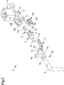
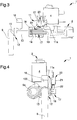
- the mixing element 12 is associated in a removable manner with the coupling element 7 between an operating configuration ( Figure 1 ) and a disassembly configuration ( Figure 2 ).
- the mixing element 12 is coupled to the coupling element 7 for the receiving of the liquid substance, thus allowing the correct operation of the device 1.
- the mixing element 12 is moved away from the coupling element 7, in order to allow servicing the mixing element in a correct manner, or replacing a used mixing element with a new one.
- the mixing element 12 comprises a mixing portion 13, adapted to receive the liquid substance and the concentrated substance to be mixed.
- the mixing portion 13 has a substantially cylindrical shape and has an inlet mouth 14 and an outlet mouth 15.
- the mixing portion 13 also comprises an auxiliary duct 16 interposed between the outlet mouth 15 and the inlet mouth 14.
- the auxiliary duct 16 is associated with storage means for the storage of a concentrated substance, e.g. fruit juice concentrate, to be mixed with the liquid substance for the production of a substance to be consumed.
- a concentrated substance e.g. fruit juice concentrate
- auxiliary duct 16 is connected to storage means by means of flexible hoses, but different solutions cannot be ruled out.
- storage means may comprise a peristaltic pump adapted to convey the concentrated substance at command in the auxiliary duct 16, and therefore in the mixing element 12.
- the mixing element 12 comprises an end portion 9 located downstream of the auxiliary duct 16 and adapted to convey the beverage at output.
- end portion 9 is associated with the outlet mouth 15 forming an extension of the mixing element 12.
- the end portion 9 has a narrowing tubular conformation and extends in a substantially vertical direction, but different solutions cannot be ruled out which provide for an extension in an inclined direction, or a different conformation, for example semi-cylindrical partially open.
- the device 1 comprises control means 17, 20 adapted to detect the operating configuration and operatively connected to the regulation assembly 2 for the activation thereof in the operating configuration, and for the deactivation thereof in the disassembly configuration.
- the control means 17, 20 are adapted to detect the configuration of the device 1, recognizing when the mixing element 12 is coupled to the coupling element 7 compared to when the mixing element 12, on the other hand, is moved away from the coupling element 7.
- control means 17, 20 are operatively connected to the regulation assembly 2 for the activation or deactivation thereof.
- control means 17, 20 comprise a reference element 17 locked together with the mixing element 12.
- the reference element 17 occupies a predefined position compared to the conveying duct 3, shown in Figure 1 .
- the reference element 17 has an elongated conformation along a direction substantially parallel to the conveying duct 3 and, in the predefined position, it is partially side by side to the duct itself.
- the reference element 17 has a fastening end 18, locked together with the mixing element 12, and an interaction end 19 having a narrowing conformation.
- the reference element 17 has a longitudinal L-shaped extension, with the interaction end 19 located in a distal position with respect to the fastening end 18.
- the reference element 17 e.g. having a squat shape, or having a zig-zag or inclined longitudinal extension, or having an inclination with respect to the mixing element 12 and/or to the conveying duct 3 different to that shown.
- the reference element 17 can be formed on the auxiliary duct 16, or coincide with the auxiliary duct itself.
- the control means 17, 20 also comprise a control device 20 adapted to interact with the reference element 17 for the detection of the predefined position.
- the control device 20 is operatively connected to the regulation assembly 2 for the control of the activation/deactivation of the latter.
- the control device 20 detects this position, therefore the operating configuration, and consequently activates the regulation assembly, thus making it possible to deliver the liquid substance.
- control device 20 is positioned on the holding portion 11. This way, the control device 20 is located at the regulation element 4, so as to facilitate the connection thereof.
- control device 20 comprises a control element 21 operatively connected to the regulation assembly 2.
- control element 21 is operatively connected to the regulation assembly 2, allowing the activation thereof when the reference element 17 is in the predefined position.
- the control device 20 also comprises an interaction element 22 associated with it and adapted to interact with the reference element 17 when this is in the predefined position for the activation/deactivation of the regulation assembly 2.
- the interaction element 22 is electrically associated with the control element 21.
- interaction element 22 is adapted to activate and deactivate said regulation assembly 2 as a result of the displacement of said interaction element 22 from a rest position to an active position and vice versa.
- the regulation assembly 2 is deactivated, since the relative electric circuit is open, whereas when the interaction element 22 achieves the active position, the electric circuit is closed, thus resulting in the activation of the regulation assembly 2.
- the control element 21 is preferably of the type of a known electric apparatus, provided with electric circuits, not shown in the figures, which are interchangeable for conveying one or more electric pulses to the regulation assembly 2 in order to activate or deactivate it.
- the interaction element 22 is of the type of a limit switch element, e.g. a button or an operating lever.
- the limit switch element is adapted to open/close or switch the electric circuits of the control element 21 in order to activate or deactivate the regulation assembly 2.
- control device 20 of the type of a "micro switch", the interaction element 22 of which can be lifted by the reference element 17 when this moves to the predefined position.
- the lifting and lowering of the interaction element 22 causes the switch of the circuits present in the control element 21, transmitting to the regulation assembly 2 an activation and deactivation pulse respectively.
- the interaction element 22 being the type of a relay.
- the interaction element 22 is electronically associated with the control element 21.
- the interaction element 22 conveys an electronic signal to the control element 21 diversified according to whether or not the reference element 17 is in the predefined position.
- the interaction element is of the type of an optical sensor, adapted to detect the presence of the reference element 17 in the predefined position.
- the optical sensor there are other types of sensors, e.g. pressure or magnetic sensors.
- the operation of the present invention is as follows and, in order to better understand the invention forming the subject of the present invention, it refers to a device 1 used for beverage dispensing machines.
- the conveying duct 3 is adapted to convey water into the mixing element 12 where it is mixed with the concentrated substance in order to produce the drink to be consumed.
- the mixing element 12 is moved away from the conveying duct 3 and the interaction element 22 does not interact with the interaction element 22.
- control device 20 deactivates the regulation assembly 2, making it impossible to deliver water through the conveying duct 3.
- the regulation element 4 operates a barrier of the conveying duct 3 adapted to prevent water outflow, whereas the control device 20 prevents the regulation element 4 from being activated to allow the outflow of the water itself.
- the mixing element 12 and the conveying duct 3 are communicating through the coupling element 7 and the water can flow out of the duct inside the mixing element itself.
- the reference element 17 is in the predefined position and interacts with the interaction element 22 of the control device 20, connecting the latter to the regulation assembly 2 and activating it.
- the interaction element 22 operates on the circuits of the control element 21, with the latter enabling the possible operation of the regulation element 4.
- the reference element 17 progressing towards the predefined position, lifts the interaction element 22.
- the narrowing conformation of the interaction end 19 facilitates the correct interaction between the interaction element 22 and the reference element 17 during the passage from the disassembly configuration to the operating configuration.
- the interaction element 22 lifted in approach to the control element 21, switches the circuits present in the latter and activates the regulation assembly 2.
- the reference element 17 in the predefined position is detected by the interaction element 22, which transmits a corresponding electronic signal to the control element 21.
- the latter by receiving the electronic signal relating to the detection of the interaction element 22 in the predefined position, activates the detection assembly.
- the control means in fact, prevent the water from being dispensed in case of the mixing element not being fitted, avoiding inconvenience due to non-dispensing of the beverage or due to the uncontrolled spillage of water on the surfaces or in the dispensing machines.
- control means in particular the interaction between the control device and the reference element placed on the mixing element, makes it possible to minimize the waste of substances to be dispensed.
- control means make it possible to detect the operating configuration and, therefore, to activate/deactivate the regulation assembly.
- the ending device for dispensing machines makes it possible to facilitate the maintenance operations of the machines themselves, allowing the disassembly and/or replacement of the mixing element without interrupting the entire operation of the machine, but only deactivating the regulation assembly relating to a limited number of beverages to be dispensed.
Landscapes
- Devices For Dispensing Beverages (AREA)
- Electrical Discharge Machining, Electrochemical Machining, And Combined Machining (AREA)
- Reverberation, Karaoke And Other Acoustics (AREA)
- Paper (AREA)
Claims (11)
- Dispositif de fin (1) pour machines de distribution comprenant :- un ensemble de régulation (2) activable pour la régulation de l'écoulement sortant d'une substance liquide à mélanger, ayant au moins un élément de couplage (7) adapté pour transporter ladite substance liquide à une sortie ;- au moins un élément de mélange (12) dans lequel ladite substance liquide est transportable pour la mélanger avec une substance concentrée pour former une substance à consommer, associé de manière amovible audit élément de couplage (7) entre une configuration de fonctionnement, dans laquelle ledit élément de mélange (12) est couplé audit élément de couplage (7) pour la réception de ladite substance liquide, et une configuration de démontage, dans laquelle ledit élément de mélange (12) est retiré dudit élément de couplage (7) ;caractérisé par le fait qu'il comprend des moyens de commande (17, 20) adaptés pour détecter ladite configuration de fonctionnement et reliés opérationnellement audit ensemble de régulation (2) pour l'activation de ce dernier dans la configuration de fonctionnement et pour la désactivation de ce dernier dans la configuration de démontage.
- Dispositif (1) selon la revendication 1, caractérisé par le fait que lesdits moyens de commande (17, 20) comprennent :- un élément de référence (17) verrouillé conjointement avec ledit élément de mélange (12) et occupant une position prédéfinie dans ladite configuration de fonctionnement ;- un dispositif de commande (20) adapté pour interagir avec ledit élément de référence (17) pour la détection de ladite position prédéfinie, et relié opérationnellement audit ensemble de régulation (2) pour la commande de l'activation/la désactivation de ce dernier.
- Dispositif (1) selon la revendication 2, caractérisé par le fait que ledit dispositif de commande (20) comprend :- un élément de commande (21) relié opérationnellement audit ensemble de régulation (2) ; et- un élément d'interaction (22) associé audit élément de commande (21) et adapté pour interagir avec ledit élément de référence (17) lorsque celui-ci est à la position prédéfinie pour l'activation/désactivation dudit ensemble de régulation (2).
- Dispositif (1) selon la revendication 3, caractérisé par le fait que ledit élément d'interaction (22) est électriquement associé audit élément de commande (21) adapté pour activer et désactiver ledit ensemble de régulation (2) sous l'effet du déplacement dudit élément d'interaction (22) depuis une position de repos jusqu'à une position active et vice-versa.
- Dispositif (1) selon la revendication 4, caractérisé par le fait que ledit élément d'interaction (22) est du type d'un élément de commutation de limite.
- Dispositif (1) selon la revendication 3, caractérisé par le fait que ledit élément d'interaction (22) est électroniquement associé audit élément de commande (21).
- Dispositif (1) selon la revendication 6, caractérisé par le fait que ledit élément d'interaction (22) est du type d'un capteur optique.
- Dispositif (1) selon une ou plusieurs des revendications précédentes, caractérisé par le fait que ledit ensemble de régulation (2) comprend :- au moins un conduit de transport (3) de ladite substance liquide ;- au moins un élément de régulation (4) associé auxdits moyens de commande (17, 20) pour la régulation de l'écoulement sortant de ladite substance liquide.
- Dispositif (1) selon la revendication 8, caractérisé par le fait que ledit élément de couplage (7) est couplé audit conduit de transport (3) et est positionné en aval dudit élément de régulation (4).
- Dispositif (1) selon la revendication 8 ou 9, caractérisé par le fait que ledit élément de couplage (7) est couplé de manière amovible audit conduit de transport (3).
- Dispositif (1) selon la revendication 2 ou l'une quelconque des revendications 3 à 10 dépendant de la revendication 2, caractérisé par le fait que ledit élément de couplage (7) comprend une portion de maintien (11) sur laquelle ledit dispositif de commande (20) est placé.
Applications Claiming Priority (2)
| Application Number | Priority Date | Filing Date | Title |
|---|---|---|---|
| IT102016000124466A IT201600124466A1 (it) | 2016-12-07 | 2016-12-07 | Dispositivo terminale per macchine erogatrici |
| PCT/IB2017/057728 WO2018104905A1 (fr) | 2016-12-07 | 2017-12-07 | Dispositif de fin pour machines de distribution |
Publications (2)
| Publication Number | Publication Date |
|---|---|
| EP3551572A1 EP3551572A1 (fr) | 2019-10-16 |
| EP3551572B1 true EP3551572B1 (fr) | 2021-03-03 |
Family
ID=58455474
Family Applications (1)
| Application Number | Title | Priority Date | Filing Date |
|---|---|---|---|
| EP17823219.5A Active EP3551572B1 (fr) | 2016-12-07 | 2017-12-07 | Dispositif de fin pour machines de distribution |
Country Status (4)
| Country | Link |
|---|---|
| EP (1) | EP3551572B1 (fr) |
| ES (1) | ES2875332T3 (fr) |
| IT (1) | IT201600124466A1 (fr) |
| WO (1) | WO2018104905A1 (fr) |
Family Cites Families (3)
| Publication number | Priority date | Publication date | Assignee | Title |
|---|---|---|---|---|
| US6387424B2 (en) * | 1999-12-17 | 2002-05-14 | Bunn-O-Matic Corporation | Conductance based control system and method |
| WO2010129833A1 (fr) * | 2009-05-07 | 2010-11-11 | Newage Industries, Inc | Utilisation de contrôleurs rfid multiplexés pour vérifier les connexions dans des systèmes automatisés |
| DE102013110020A1 (de) * | 2013-09-12 | 2015-03-12 | as Strömungstechnik GmbH | Entnahmesystem |
-
2016
- 2016-12-07 IT IT102016000124466A patent/IT201600124466A1/it unknown
-
2017
- 2017-12-07 ES ES17823219T patent/ES2875332T3/es active Active
- 2017-12-07 EP EP17823219.5A patent/EP3551572B1/fr active Active
- 2017-12-07 WO PCT/IB2017/057728 patent/WO2018104905A1/fr not_active Ceased
Non-Patent Citations (1)
| Title |
|---|
| None * |
Also Published As
| Publication number | Publication date |
|---|---|
| WO2018104905A1 (fr) | 2018-06-14 |
| IT201600124466A1 (it) | 2018-06-07 |
| ES2875332T3 (es) | 2021-11-10 |
| EP3551572A1 (fr) | 2019-10-16 |
Similar Documents
| Publication | Publication Date | Title |
|---|---|---|
| EP3386907B1 (fr) | Système hybride et procédé de production de boissons avec gaz injecté sensiblement non moussantes et moussantes | |
| US10604398B2 (en) | Method and apparatus for post-mix drink dispensing | |
| EP3518713B1 (fr) | Dispositif d'émulsion de lait à effet venturi et procédé de production de lait chaud avec et sans mousse à l'aide du dispositif | |
| US20210235920A1 (en) | Apparatuses, systems, and methods for brewing a beverage | |
| EP3305144B1 (fr) | Dispositif émulsifiant de lait à venturi | |
| EP3102317B1 (fr) | Unité de carbonatation | |
| US20140327162A1 (en) | Milk-frothing apparatus, and coffee or espresso machine and automatic beverage vending machine having a milk-frothing apparatus of this kind | |
| US7555979B2 (en) | Apparatus for producing a beverage | |
| EP3826959B1 (fr) | Distributeur de liquide pour distribuer de l'eau et une boisson aromatisée | |
| EP2817254B1 (fr) | Distributeur d'eau potable | |
| EP3162257B1 (fr) | Appareil de production d'une boisson comprenant une machine à café et un récipient pour un produit alimentaire liquide | |
| ITMI951558A1 (it) | Macchina con controllo di livello per la produzione ed erogazione di bevande raffreddate o di granite | |
| CO2022015015A2 (es) | Sistema dispensador de líquidos, conjunto de control de flujo de líquidos y dispensador de líquidos para dispensar líquidos a diferentes temperaturas | |
| GB2444718A (en) | A level control device for a dispensing tap | |
| WO2018104905A1 (fr) | Dispositif de fin pour machines de distribution | |
| JP7175400B2 (ja) | 配分制御装置、及び配分設備 | |
| JP2010189053A (ja) | 飲料注出装置 | |
| EP4236731B1 (fr) | Ensemble de distribution pour distribuer un produit alimentaire fluide | |
| US20240417961A1 (en) | Sanitary fitting and method for dispensing a liquid using a sanitary fitting | |
| DK165049B (da) | Fortyndingsventil til fortynding af flydende koncentrater med flydende fortyndingsmidler, navnlig til fortynding af et flydende foderkoncentrat til smaagrise med vand, samt fodringsautomat til smaagrise indbefattende en saadan fortyndingsventil |
Legal Events
| Date | Code | Title | Description |
|---|---|---|---|
| STAA | Information on the status of an ep patent application or granted ep patent |
Free format text: STATUS: UNKNOWN |
|
| STAA | Information on the status of an ep patent application or granted ep patent |
Free format text: STATUS: THE INTERNATIONAL PUBLICATION HAS BEEN MADE |
|
| PUAI | Public reference made under article 153(3) epc to a published international application that has entered the european phase |
Free format text: ORIGINAL CODE: 0009012 |
|
| STAA | Information on the status of an ep patent application or granted ep patent |
Free format text: STATUS: REQUEST FOR EXAMINATION WAS MADE |
|
| 17P | Request for examination filed |
Effective date: 20190528 |
|
| AK | Designated contracting states |
Kind code of ref document: A1 Designated state(s): AL AT BE BG CH CY CZ DE DK EE ES FI FR GB GR HR HU IE IS IT LI LT LU LV MC MK MT NL NO PL PT RO RS SE SI SK SM TR |
|
| AX | Request for extension of the european patent |
Extension state: BA ME |
|
| DAV | Request for validation of the european patent (deleted) | ||
| DAX | Request for extension of the european patent (deleted) | ||
| GRAP | Despatch of communication of intention to grant a patent |
Free format text: ORIGINAL CODE: EPIDOSNIGR1 |
|
| STAA | Information on the status of an ep patent application or granted ep patent |
Free format text: STATUS: GRANT OF PATENT IS INTENDED |
|
| INTG | Intention to grant announced |
Effective date: 20200929 |
|
| GRAS | Grant fee paid |
Free format text: ORIGINAL CODE: EPIDOSNIGR3 |
|
| GRAA | (expected) grant |
Free format text: ORIGINAL CODE: 0009210 |
|
| STAA | Information on the status of an ep patent application or granted ep patent |
Free format text: STATUS: THE PATENT HAS BEEN GRANTED |
|
| AK | Designated contracting states |
Kind code of ref document: B1 Designated state(s): AL AT BE BG CH CY CZ DE DK EE ES FI FR GB GR HR HU IE IS IT LI LT LU LV MC MK MT NL NO PL PT RO RS SE SI SK SM TR |
|
| REG | Reference to a national code |
Ref country code: GB Ref legal event code: FG4D |
|
| REG | Reference to a national code |
Ref country code: AT Ref legal event code: REF Ref document number: 1367009 Country of ref document: AT Kind code of ref document: T Effective date: 20210315 Ref country code: CH Ref legal event code: EP |
|
| REG | Reference to a national code |
Ref country code: DE Ref legal event code: R096 Ref document number: 602017034002 Country of ref document: DE |
|
| REG | Reference to a national code |
Ref country code: IE Ref legal event code: FG4D |
|
| REG | Reference to a national code |
Ref country code: LT Ref legal event code: MG9D |
|
| PG25 | Lapsed in a contracting state [announced via postgrant information from national office to epo] |
Ref country code: GR Free format text: LAPSE BECAUSE OF FAILURE TO SUBMIT A TRANSLATION OF THE DESCRIPTION OR TO PAY THE FEE WITHIN THE PRESCRIBED TIME-LIMIT Effective date: 20210604 Ref country code: FI Free format text: LAPSE BECAUSE OF FAILURE TO SUBMIT A TRANSLATION OF THE DESCRIPTION OR TO PAY THE FEE WITHIN THE PRESCRIBED TIME-LIMIT Effective date: 20210303 Ref country code: HR Free format text: LAPSE BECAUSE OF FAILURE TO SUBMIT A TRANSLATION OF THE DESCRIPTION OR TO PAY THE FEE WITHIN THE PRESCRIBED TIME-LIMIT Effective date: 20210303 Ref country code: NO Free format text: LAPSE BECAUSE OF FAILURE TO SUBMIT A TRANSLATION OF THE DESCRIPTION OR TO PAY THE FEE WITHIN THE PRESCRIBED TIME-LIMIT Effective date: 20210603 Ref country code: BG Free format text: LAPSE BECAUSE OF FAILURE TO SUBMIT A TRANSLATION OF THE DESCRIPTION OR TO PAY THE FEE WITHIN THE PRESCRIBED TIME-LIMIT Effective date: 20210603 Ref country code: LT Free format text: LAPSE BECAUSE OF FAILURE TO SUBMIT A TRANSLATION OF THE DESCRIPTION OR TO PAY THE FEE WITHIN THE PRESCRIBED TIME-LIMIT Effective date: 20210303 |
|
| REG | Reference to a national code |
Ref country code: NL Ref legal event code: MP Effective date: 20210303 |
|
| REG | Reference to a national code |
Ref country code: AT Ref legal event code: MK05 Ref document number: 1367009 Country of ref document: AT Kind code of ref document: T Effective date: 20210303 |
|
| PG25 | Lapsed in a contracting state [announced via postgrant information from national office to epo] |
Ref country code: SE Free format text: LAPSE BECAUSE OF FAILURE TO SUBMIT A TRANSLATION OF THE DESCRIPTION OR TO PAY THE FEE WITHIN THE PRESCRIBED TIME-LIMIT Effective date: 20210303 Ref country code: PL Free format text: LAPSE BECAUSE OF FAILURE TO SUBMIT A TRANSLATION OF THE DESCRIPTION OR TO PAY THE FEE WITHIN THE PRESCRIBED TIME-LIMIT Effective date: 20210303 Ref country code: LV Free format text: LAPSE BECAUSE OF FAILURE TO SUBMIT A TRANSLATION OF THE DESCRIPTION OR TO PAY THE FEE WITHIN THE PRESCRIBED TIME-LIMIT Effective date: 20210303 Ref country code: RS Free format text: LAPSE BECAUSE OF FAILURE TO SUBMIT A TRANSLATION OF THE DESCRIPTION OR TO PAY THE FEE WITHIN THE PRESCRIBED TIME-LIMIT Effective date: 20210303 |
|
| PG25 | Lapsed in a contracting state [announced via postgrant information from national office to epo] |
Ref country code: NL Free format text: LAPSE BECAUSE OF FAILURE TO SUBMIT A TRANSLATION OF THE DESCRIPTION OR TO PAY THE FEE WITHIN THE PRESCRIBED TIME-LIMIT Effective date: 20210303 |
|
| PG25 | Lapsed in a contracting state [announced via postgrant information from national office to epo] |
Ref country code: SM Free format text: LAPSE BECAUSE OF FAILURE TO SUBMIT A TRANSLATION OF THE DESCRIPTION OR TO PAY THE FEE WITHIN THE PRESCRIBED TIME-LIMIT Effective date: 20210303 Ref country code: AT Free format text: LAPSE BECAUSE OF FAILURE TO SUBMIT A TRANSLATION OF THE DESCRIPTION OR TO PAY THE FEE WITHIN THE PRESCRIBED TIME-LIMIT Effective date: 20210303 Ref country code: CZ Free format text: LAPSE BECAUSE OF FAILURE TO SUBMIT A TRANSLATION OF THE DESCRIPTION OR TO PAY THE FEE WITHIN THE PRESCRIBED TIME-LIMIT Effective date: 20210303 Ref country code: EE Free format text: LAPSE BECAUSE OF FAILURE TO SUBMIT A TRANSLATION OF THE DESCRIPTION OR TO PAY THE FEE WITHIN THE PRESCRIBED TIME-LIMIT Effective date: 20210303 |
|
| REG | Reference to a national code |
Ref country code: ES Ref legal event code: FG2A Ref document number: 2875332 Country of ref document: ES Kind code of ref document: T3 Effective date: 20211110 |
|
| PG25 | Lapsed in a contracting state [announced via postgrant information from national office to epo] |
Ref country code: PT Free format text: LAPSE BECAUSE OF FAILURE TO SUBMIT A TRANSLATION OF THE DESCRIPTION OR TO PAY THE FEE WITHIN THE PRESCRIBED TIME-LIMIT Effective date: 20210705 Ref country code: RO Free format text: LAPSE BECAUSE OF FAILURE TO SUBMIT A TRANSLATION OF THE DESCRIPTION OR TO PAY THE FEE WITHIN THE PRESCRIBED TIME-LIMIT Effective date: 20210303 Ref country code: SK Free format text: LAPSE BECAUSE OF FAILURE TO SUBMIT A TRANSLATION OF THE DESCRIPTION OR TO PAY THE FEE WITHIN THE PRESCRIBED TIME-LIMIT Effective date: 20210303 Ref country code: IS Free format text: LAPSE BECAUSE OF FAILURE TO SUBMIT A TRANSLATION OF THE DESCRIPTION OR TO PAY THE FEE WITHIN THE PRESCRIBED TIME-LIMIT Effective date: 20210703 |
|
| REG | Reference to a national code |
Ref country code: DE Ref legal event code: R097 Ref document number: 602017034002 Country of ref document: DE |
|
| PLBE | No opposition filed within time limit |
Free format text: ORIGINAL CODE: 0009261 |
|
| STAA | Information on the status of an ep patent application or granted ep patent |
Free format text: STATUS: NO OPPOSITION FILED WITHIN TIME LIMIT |
|
| PG25 | Lapsed in a contracting state [announced via postgrant information from national office to epo] |
Ref country code: DK Free format text: LAPSE BECAUSE OF FAILURE TO SUBMIT A TRANSLATION OF THE DESCRIPTION OR TO PAY THE FEE WITHIN THE PRESCRIBED TIME-LIMIT Effective date: 20210303 Ref country code: AL Free format text: LAPSE BECAUSE OF FAILURE TO SUBMIT A TRANSLATION OF THE DESCRIPTION OR TO PAY THE FEE WITHIN THE PRESCRIBED TIME-LIMIT Effective date: 20210303 |
|
| 26N | No opposition filed |
Effective date: 20211206 |
|
| PG25 | Lapsed in a contracting state [announced via postgrant information from national office to epo] |
Ref country code: SI Free format text: LAPSE BECAUSE OF FAILURE TO SUBMIT A TRANSLATION OF THE DESCRIPTION OR TO PAY THE FEE WITHIN THE PRESCRIBED TIME-LIMIT Effective date: 20210303 |
|
| PG25 | Lapsed in a contracting state [announced via postgrant information from national office to epo] |
Ref country code: IS Free format text: LAPSE BECAUSE OF FAILURE TO SUBMIT A TRANSLATION OF THE DESCRIPTION OR TO PAY THE FEE WITHIN THE PRESCRIBED TIME-LIMIT Effective date: 20210703 |
|
| PG25 | Lapsed in a contracting state [announced via postgrant information from national office to epo] |
Ref country code: MC Free format text: LAPSE BECAUSE OF FAILURE TO SUBMIT A TRANSLATION OF THE DESCRIPTION OR TO PAY THE FEE WITHIN THE PRESCRIBED TIME-LIMIT Effective date: 20210303 |
|
| REG | Reference to a national code |
Ref country code: CH Ref legal event code: PL |
|
| GBPC | Gb: european patent ceased through non-payment of renewal fee |
Effective date: 20211207 |
|
| REG | Reference to a national code |
Ref country code: BE Ref legal event code: MM Effective date: 20211231 |
|
| PG25 | Lapsed in a contracting state [announced via postgrant information from national office to epo] |
Ref country code: LU Free format text: LAPSE BECAUSE OF NON-PAYMENT OF DUE FEES Effective date: 20211207 Ref country code: IE Free format text: LAPSE BECAUSE OF NON-PAYMENT OF DUE FEES Effective date: 20211207 Ref country code: GB Free format text: LAPSE BECAUSE OF NON-PAYMENT OF DUE FEES Effective date: 20211207 |
|
| PG25 | Lapsed in a contracting state [announced via postgrant information from national office to epo] |
Ref country code: BE Free format text: LAPSE BECAUSE OF NON-PAYMENT OF DUE FEES Effective date: 20211231 |
|
| PG25 | Lapsed in a contracting state [announced via postgrant information from national office to epo] |
Ref country code: LI Free format text: LAPSE BECAUSE OF NON-PAYMENT OF DUE FEES Effective date: 20211231 Ref country code: CH Free format text: LAPSE BECAUSE OF NON-PAYMENT OF DUE FEES Effective date: 20211231 |
|
| PG25 | Lapsed in a contracting state [announced via postgrant information from national office to epo] |
Ref country code: CY Free format text: LAPSE BECAUSE OF FAILURE TO SUBMIT A TRANSLATION OF THE DESCRIPTION OR TO PAY THE FEE WITHIN THE PRESCRIBED TIME-LIMIT Effective date: 20210303 |
|
| PG25 | Lapsed in a contracting state [announced via postgrant information from national office to epo] |
Ref country code: HU Free format text: LAPSE BECAUSE OF FAILURE TO SUBMIT A TRANSLATION OF THE DESCRIPTION OR TO PAY THE FEE WITHIN THE PRESCRIBED TIME-LIMIT; INVALID AB INITIO Effective date: 20171207 |
|
| PG25 | Lapsed in a contracting state [announced via postgrant information from national office to epo] |
Ref country code: MK Free format text: LAPSE BECAUSE OF FAILURE TO SUBMIT A TRANSLATION OF THE DESCRIPTION OR TO PAY THE FEE WITHIN THE PRESCRIBED TIME-LIMIT Effective date: 20210303 |
|
| PG25 | Lapsed in a contracting state [announced via postgrant information from national office to epo] |
Ref country code: TR Free format text: LAPSE BECAUSE OF FAILURE TO SUBMIT A TRANSLATION OF THE DESCRIPTION OR TO PAY THE FEE WITHIN THE PRESCRIBED TIME-LIMIT Effective date: 20210303 |
|
| PG25 | Lapsed in a contracting state [announced via postgrant information from national office to epo] |
Ref country code: MT Free format text: LAPSE BECAUSE OF FAILURE TO SUBMIT A TRANSLATION OF THE DESCRIPTION OR TO PAY THE FEE WITHIN THE PRESCRIBED TIME-LIMIT Effective date: 20210303 |
|
| PGFP | Annual fee paid to national office [announced via postgrant information from national office to epo] |
Ref country code: IT Payment date: 20251222 Year of fee payment: 9 |
|
| PGFP | Annual fee paid to national office [announced via postgrant information from national office to epo] |
Ref country code: FR Payment date: 20251226 Year of fee payment: 9 |
|
| PGFP | Annual fee paid to national office [announced via postgrant information from national office to epo] |
Ref country code: ES Payment date: 20260102 Year of fee payment: 9 |
|
| PGFP | Annual fee paid to national office [announced via postgrant information from national office to epo] |
Ref country code: DE Payment date: 20251229 Year of fee payment: 9 |