EP3551862B1 - Verbrennungsvorkammervorrichtung für einen verbrennungsmotor - Google Patents
Verbrennungsvorkammervorrichtung für einen verbrennungsmotor Download PDFInfo
- Publication number
- EP3551862B1 EP3551862B1 EP17877515.1A EP17877515A EP3551862B1 EP 3551862 B1 EP3551862 B1 EP 3551862B1 EP 17877515 A EP17877515 A EP 17877515A EP 3551862 B1 EP3551862 B1 EP 3551862B1
- Authority
- EP
- European Patent Office
- Prior art keywords
- chamber
- combustion
- bores
- combustion pre
- bore
- Prior art date
- Legal status (The legal status is an assumption and is not a legal conclusion. Google has not performed a legal analysis and makes no representation as to the accuracy of the status listed.)
- Active
Links
Images


Classifications
-
- F—MECHANICAL ENGINEERING; LIGHTING; HEATING; WEAPONS; BLASTING
- F01—MACHINES OR ENGINES IN GENERAL; ENGINE PLANTS IN GENERAL; STEAM ENGINES
- F01P—COOLING OF MACHINES OR ENGINES IN GENERAL; COOLING OF INTERNAL-COMBUSTION ENGINES
- F01P3/00—Liquid cooling
- F01P3/02—Arrangements for cooling cylinders or cylinder heads
-
- F—MECHANICAL ENGINEERING; LIGHTING; HEATING; WEAPONS; BLASTING
- F01—MACHINES OR ENGINES IN GENERAL; ENGINE PLANTS IN GENERAL; STEAM ENGINES
- F01P—COOLING OF MACHINES OR ENGINES IN GENERAL; COOLING OF INTERNAL-COMBUSTION ENGINES
- F01P3/00—Liquid cooling
- F01P3/12—Arrangements for cooling other engine or machine parts
- F01P3/16—Arrangements for cooling other engine or machine parts for cooling fuel injectors or sparking-plugs
-
- F—MECHANICAL ENGINEERING; LIGHTING; HEATING; WEAPONS; BLASTING
- F02—COMBUSTION ENGINES; HOT-GAS OR COMBUSTION-PRODUCT ENGINE PLANTS
- F02B—INTERNAL-COMBUSTION PISTON ENGINES; COMBUSTION ENGINES IN GENERAL
- F02B19/00—Engines characterised by precombustion chambers
- F02B19/10—Engines characterised by precombustion chambers with fuel introduced partly into pre-combustion chamber, and partly into cylinder
- F02B19/1004—Engines characterised by precombustion chambers with fuel introduced partly into pre-combustion chamber, and partly into cylinder details of combustion chamber, e.g. mounting arrangements
- F02B19/1009—Engines characterised by precombustion chambers with fuel introduced partly into pre-combustion chamber, and partly into cylinder details of combustion chamber, e.g. mounting arrangements heating, cooling
-
- F—MECHANICAL ENGINEERING; LIGHTING; HEATING; WEAPONS; BLASTING
- F02—COMBUSTION ENGINES; HOT-GAS OR COMBUSTION-PRODUCT ENGINE PLANTS
- F02B—INTERNAL-COMBUSTION PISTON ENGINES; COMBUSTION ENGINES IN GENERAL
- F02B19/00—Engines characterised by precombustion chambers
- F02B19/12—Engines characterised by precombustion chambers with positive ignition
-
- F—MECHANICAL ENGINEERING; LIGHTING; HEATING; WEAPONS; BLASTING
- F02—COMBUSTION ENGINES; HOT-GAS OR COMBUSTION-PRODUCT ENGINE PLANTS
- F02B—INTERNAL-COMBUSTION PISTON ENGINES; COMBUSTION ENGINES IN GENERAL
- F02B19/00—Engines characterised by precombustion chambers
- F02B19/16—Chamber shapes or constructions not specific to sub-groups F02B19/02 - F02B19/10
- F02B19/18—Transfer passages between chamber and cylinder
-
- F—MECHANICAL ENGINEERING; LIGHTING; HEATING; WEAPONS; BLASTING
- F02—COMBUSTION ENGINES; HOT-GAS OR COMBUSTION-PRODUCT ENGINE PLANTS
- F02M—SUPPLYING COMBUSTION ENGINES IN GENERAL WITH COMBUSTIBLE MIXTURES OR CONSTITUENTS THEREOF
- F02M21/00—Apparatus for supplying engines with non-liquid fuels, e.g. gaseous fuels stored in liquid form
- F02M21/02—Apparatus for supplying engines with non-liquid fuels, e.g. gaseous fuels stored in liquid form for gaseous fuels
- F02M21/0218—Details on the gaseous fuel supply system, e.g. tanks, valves, pipes, pumps, rails, injectors or mixers
- F02M21/0248—Injectors
- F02M21/0275—Injectors for in-cylinder direct injection, e.g. injector combined with spark plug
-
- F—MECHANICAL ENGINEERING; LIGHTING; HEATING; WEAPONS; BLASTING
- F02—COMBUSTION ENGINES; HOT-GAS OR COMBUSTION-PRODUCT ENGINE PLANTS
- F02P—IGNITION, OTHER THAN COMPRESSION IGNITION, FOR INTERNAL-COMBUSTION ENGINES; TESTING OF IGNITION TIMING IN COMPRESSION-IGNITION ENGINES
- F02P13/00—Sparking plugs structurally combined with other parts of internal-combustion engines
-
- H—ELECTRICITY
- H01—ELECTRIC ELEMENTS
- H01T—SPARK GAPS; OVERVOLTAGE ARRESTERS USING SPARK GAPS; SPARKING PLUGS; CORONA DEVICES; GENERATING IONS TO BE INTRODUCED INTO NON-ENCLOSED GASES
- H01T13/00—Sparking plugs
- H01T13/54—Sparking plugs having electrodes arranged in a partly-enclosed ignition chamber
-
- F—MECHANICAL ENGINEERING; LIGHTING; HEATING; WEAPONS; BLASTING
- F01—MACHINES OR ENGINES IN GENERAL; ENGINE PLANTS IN GENERAL; STEAM ENGINES
- F01P—COOLING OF MACHINES OR ENGINES IN GENERAL; COOLING OF INTERNAL-COMBUSTION ENGINES
- F01P3/00—Liquid cooling
- F01P3/02—Arrangements for cooling cylinders or cylinder heads
- F01P2003/024—Cooling cylinder heads
-
- F—MECHANICAL ENGINEERING; LIGHTING; HEATING; WEAPONS; BLASTING
- F02—COMBUSTION ENGINES; HOT-GAS OR COMBUSTION-PRODUCT ENGINE PLANTS
- F02M—SUPPLYING COMBUSTION ENGINES IN GENERAL WITH COMBUSTIBLE MIXTURES OR CONSTITUENTS THEREOF
- F02M21/00—Apparatus for supplying engines with non-liquid fuels, e.g. gaseous fuels stored in liquid form
- F02M21/02—Apparatus for supplying engines with non-liquid fuels, e.g. gaseous fuels stored in liquid form for gaseous fuels
- F02M21/0203—Apparatus for supplying engines with non-liquid fuels, e.g. gaseous fuels stored in liquid form for gaseous fuels characterised by the type of gaseous fuel
-
- Y—GENERAL TAGGING OF NEW TECHNOLOGICAL DEVELOPMENTS; GENERAL TAGGING OF CROSS-SECTIONAL TECHNOLOGIES SPANNING OVER SEVERAL SECTIONS OF THE IPC; TECHNICAL SUBJECTS COVERED BY FORMER USPC CROSS-REFERENCE ART COLLECTIONS [XRACs] AND DIGESTS
- Y02—TECHNOLOGIES OR APPLICATIONS FOR MITIGATION OR ADAPTATION AGAINST CLIMATE CHANGE
- Y02T—CLIMATE CHANGE MITIGATION TECHNOLOGIES RELATED TO TRANSPORTATION
- Y02T10/00—Road transport of goods or passengers
- Y02T10/10—Internal combustion engine [ICE] based vehicles
- Y02T10/12—Improving ICE efficiencies
-
- Y—GENERAL TAGGING OF NEW TECHNOLOGICAL DEVELOPMENTS; GENERAL TAGGING OF CROSS-SECTIONAL TECHNOLOGIES SPANNING OVER SEVERAL SECTIONS OF THE IPC; TECHNICAL SUBJECTS COVERED BY FORMER USPC CROSS-REFERENCE ART COLLECTIONS [XRACs] AND DIGESTS
- Y02—TECHNOLOGIES OR APPLICATIONS FOR MITIGATION OR ADAPTATION AGAINST CLIMATE CHANGE
- Y02T—CLIMATE CHANGE MITIGATION TECHNOLOGIES RELATED TO TRANSPORTATION
- Y02T10/00—Road transport of goods or passengers
- Y02T10/10—Internal combustion engine [ICE] based vehicles
- Y02T10/30—Use of alternative fuels, e.g. biofuels
Definitions
- the present application relates to internal combustion engines, and more particularly, but not exclusively relates to a combustion pre-chamber device for spark ignition engines.
- Combustion pre-chamber devices in spark ignition engines reduce engine emissions and can improve performance by reducing the timing delay and increasing the speed of heat release.
- combustion pre-chamber devices suffer from issues relating to misfire events and lowered durability of ignition systems due to the high temperatures within the combustion pre-chamber devices. Accordingly, there is a continuing demand for further contributions in this area of technology.
- One embodiment of the present application is a combustion pre-chamber device for a spark ignition internal combustion engine.
- the pre-chamber device includes a number of bores that open at an outer surface thereof that extend into the body and receive a coolant flow to provide cooling for a combustion pre-chamber of the combustion pre-chamber device.
- FIG. 1 is a cutaway schematic illustration of an internal combustion engine 100 including a combustion pre-chamber device 118.
- the engine 100 includes a cylinder head 104 defining a spark plug passage 106 and a head cooling passage 108.
- the engine 100 further includes an engine block 110 that assembles with the cylinder head 104 to form combustion chamber 114 of the engine 100.
- a piston 116 is typically provided in combustion chamber 114.
- the engine 100 is fueled with gasoline, and/or natural gas and/or related hydrocarbons such as methane, ethane, or propane.
- the engine 100 is partially fueled with natural gas, and/or is a hybrid engine using natural gas in combination with other fuels.
- the cylinder head 104 may include multiple spark plug passages 106 corresponding to each of a set of multiple cylinders in the engine block 110.
- the spark plug passage 106 receives a spark plug 112 that ordinarily exposes the spark plug electrode to the combustion chamber 114 defined by the engine block 110.
- a combustion pre-chamber device 118 is positioned in the spark plug passage 106 such that the spark plug electrode is not exposed directly to the combustion chamber 114.
- the combustion pre-chamber device 118 is a separate device that is coupled to the cylinder head 104.
- the combustion pre-chamber device 118 is formed integrally with the cylinder head 104.
- combustion pre-chamber device 118 is illustrated in isolation.
- the device 118 includes a body 201 that extends from a first (proximal) end 202 to a second (distal) end 204.
- the first end 202 and the second end 204 are formed independently and secured together to form body 201.
- the first end 202 and the second end 204 are formed as a single unit to provide an integral body 201.
- the device 118 further includes an inner surface including a first inner surface portion 206a and a second inner surface portion 206b, and an outer surface 208.
- the outer surface 208 defines a cooling channel 210 about the outer surface 208 of device 118.
- the cooling channel 210 is fluidly coupled to the head cooling passage 108 in cylinder head 104.
- the cooling channel 210 is a channel defined by the outer surface 208 and cooperates with the spark plug passage 106 and the cylinder head 104 to define a cooling jacket around the body 201 of device 118.
- the first end 202 of body 201 defines an inner spark plug passage 224 along the first inner surface 206A, the inner spark plug passage 224 defining threads 212 that receive complementary spark plug threads defined by spark plug 112.
- the inner surface 206a at the first end 202 of body 201 includes first end threads 212 that are threadingly engageable to the threads of spark plug 112.
- the second end 204 of body 201 opposite the first end 202 includes second end threads 226 along the outer surface 208 that couple to complementary threads on the cylinder head 104.
- the threads on the cylinder head 104 are the original threads intended for the spark plug 112.
- the threads on the cylinder head 104 are threads machined on the cylinder head 104 formed by tapping a larger hole in the cylinder head 104 such that the device 118 engages a larger diameter hole than originally placed in the cylinder head 104 for the spark plug 112.
- the cylinder head 104 may be formed with a larger diameter hole structured to receive a combustion pre-chamber device 118, and/or the cylinder head 104 may be formed integrally with a combustion pre-chamber device 118.
- the second end 204 of body 201 includes a distal tip that is substantially enclosed with a distal end wall 220 that includes a fluid connection with the inner passage 224 at first end 202.
- Distal end wall 220 includes a plurality of through-holes 214, 216 for communication with the combustion chamber 114.
- Second end 204 defines a combustion pre-chamber 218.
- the combustion pre-chamber 218 is configured to fluidly communicate with an electrode of the spark plug 112 when the spark plug 112 is received at the first end 202.
- the spark plug 112 includes multiple ignition sites, or electrodes, that are in fluid communication with combustion pre-chamber 218.
- the second end 204 extends into the cylinder combustion chamber 114.
- the distal end wall 220 of second end 204 is located in the cylinder combustion chamber 114 sufficiently such that the through-holes 214, 216 communicate with the cylinder combustion chamber 114 to receive the charge air and fuel without interfering with the piston 116.
- the second end 204 includes a plurality of circumferential through-holes 214 that are positioned around distal end wall 220 at the circumference of the second end 204, but do not extend through distal end wall 220.
- the first through-holes 214 provide fluid coupling between the combustion pre-chamber 218 and the cylinder combustion chamber 114.
- the second end 204 includes at least one tip through-hole 216 near a center of the distal end wall 220.
- the tip through-hole(s) 216 may be at the center of the distal end wall 220 or near the center of the distal end wall 220.
- the spark plug 112, the spark plug passage 106, and the combustion pre-chamber device 118 may share a common central longitudinal axis 222.
- the tip through-hole(s) 216 may be aligned with the central longitudinal axis 222, or may be aligned at an angle oblique to the central longitudinal axis 222.
- the tip through-hole(s) 216 are formed near a location on the distal end wall 220 that is expected to experience the highest temperatures, for example near the center of the combustion chamber 114.
- the distal end wall 220 includes at least two tip through-holes 216 defined along axes parallel to and near the central longitudinal axis 222.
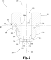
- At least one cylindrically-shaped, elongated bore 300 is formed within the body 201.
- An exemplary representation of cross-sectional view of a bore 300 is shown in FIG. 2 .
- Bore 300 has an outer end opening 302 at outer surface 208 of the device 118. In the illustrated embodiment, outer end opening 302 is located in cooling channel 210.
- Bore 300 extends along a longitudinal axis from the outer end opening 302 to a blind or closed inner end 304 positioned within the material of the body 201 of the device 118.
- Bore 300 is representative of a plurality of bores formed within the body 201 of the device 118 that extend in a first direction and orientation relative to central longitudinal axis 222. For example, a view of a second bore 350 is depicted in FIG.
- the bores 300, 350 extend in a plurality of different directions within the body 201.
- the bores 300, 350 provide a heat transfer environment that reduces the temperature of the distal end wall 220 during combustion, which may prevent pre-spark detonation of fuel and may improve the reliability of the combustion pre-chamber device 118.
- each one of the bores 300 has an end opening 302 positioned at a point along the circumference of a circle C defining an outer boundary or perimeter of the body 201 at the position of the cooling channel 210.
- a dotted line C shown in FIG. 2 represents a position of a plane of such a circle in the illustrated embodiment. As indicated in the configuration shown in FIG. 2 , the line C may be perpendicular to the central longitudinal axis 222 of the device 118, and accordingly may also represent a central horizontal axis C of the device 118, in certain embodiments.
- bores 300 may extend radially from and intersect central longitudinal axis 222 and bores 350 may be offset from and tangentially oriented relative to central longitudinal axis 222 so as to not intersect central longitudinal axis 222.
- FIG. 3 is a schematic illustration of a side view of the combustion pre-chamber device 118 with a partial cutaway view of a distal tip area of the device.
- the combustion pre-chamber device 118 has a plurality of bores 300, 350 as described above.
- Bores 300, 350 each include an end opening located on a circumference of a circular or near-circular shape defining the outer boundary of the body 201 at the position of the cooling channel 210.
- Around the circumference of the circle are a series of outer end openings 302, 352 of respective bores 300, 350.
- FIG. 3 is a schematic illustration of a side view of the combustion pre-chamber device 118 with a partial cutaway view of a distal tip area of the device.
- the combustion pre-chamber device 118 has a plurality of bores 300, 350 as described above.
- Bores 300, 350 each include an end opening located on a circumference of a circular or near-circular shape defining the outer boundary of the body 201
- a horizontal plane bisecting the ring-shaped cooling channel 210 need not be perpendicular to the central longitudinal axis 222 of the device 118.
- Dotted line C' as shown depicts such a non-perpendicular plane of the cooling channel 210.
- FIG. 4 is a schematic illustration of a cross-sectional view of spark plug 112 and another embodiment combustion pre-chamber device 118' installed in cylinder head 104.
- Device 118' is similar to device 118, but device 118' includes a combustion pre-chamber 218' that forms a primary volume 502 and a secondary volume 504.
- the device 118' includes bores 300 and 350 formed in the body 201 for receiving a fooling fluid as previously described with respect to device 118.
- the cylinder head 104 includes spark plug channel 106 that may be fabricated or machined to receive the device 118, 118'.
- the cylinder head 104 also includes head cooling passage 108 fluidly coupled to an enlarged passageway (the spark plug channel 106), for example by a machined channel 402 between at least a portion of the head cooling passage 108 and the spark plug channel 106.
- the combustion pre-chamber device 118, 118' includes the cooling channel 210 defined by outer surface 208 that cooperates with the spark plug passage 106 and the cylinder head cooling passage 108 to define a cooling jacket around the second end 204 of device 118, 118'.
- a coolant fluid may be introduced into the cooling channel 210 from cooling passage 108.
- the device 118' receives the spark plug 112 in an installed position such that the electrode 506 of the spark plug 112 is positioned in the combustion pre- chamber 218'.
- the combustion pre-chamber 218' of the device 118' may be formed in a stepped cylindrical shape along its first and second inner surfaces 206a' and 206b', such that the combustion pre- chamber 218' has a primary volume 502 of a lesser radius than that of the secondary volume 504.
- Secondary volume 504 extends around electrode 506 and primary volume 504 is located distally of electrode 506 within the combustion pre-chamber 218' when the spark plug 112 is received in the inner spark plug passage 224 of device 218'.
- the spark plug 112 ignites an air-fuel mixture in the primary volume 502 of the combustion pre- chamber 218', and residual ignition gas (e.g. combustion products) flow into the secondary volume 504 of the combustion pre- chamber 218' and away from the electrode 506 of the spark plug 112.
- the secondary volume 504 clears residual gas and combustion byproducts from the spark plug gap at the electrode 506.
- the spark plug 112 may be replaced periodically, for example on a maintenance schedule or as part of a repair operation.
- the combustion pre-chamber device 118, 118' may be replaced periodically, for example on a maintenance schedule or as part of a repair operation.
- the spark plug 112 is removed and replaced after a first period of time, and the combustion pre-chamber device 118, 118' is removed and replaced after a second period of time.
- bore 300 is shown as a hole in the plane of the cross-section of body 201 of the device 118', because the longitudinal axis of the bore 350 is at a different angle and orientation than that of the longitudinal axis of bore 300 relative to the central longitudinal axis 222 of the device 118'.
- bore 300 is oblique to central longitudinal axis 222 and also extends in a proximal and distal direction toward central longitudinal axis 222 so that bore 300 is radially oriented and the extension of the longitudinal axis of bore 300 intersects central longitudinal axis 222.
- Bore 350 is tangentially oriented to central longitudinal axis 222 and more parallel or generally parallel to a plane that is orthogonal to central longitudinal axis 222.
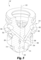
- FIG. 5 is a schematic illustration of a perspective view of the combustion pre- chamber device 118' with a partial cutaway of the view to show bores 300, 350 within the device 118'.
- exemplary bores 300, 350 are depicted along their respective longitudinal axes.
- the end openings 302 and 352 open at cooling channel 210.
- the cylindrically-shaped bore 350 extends along a longitudinal axis in a direction tangential to a circle around central longitudinal axis 222 to a closed end 354 of the bore 350 positioned distally closer to the distal end wall 220 of the device 118.
- a bore 300 has an open end 302 that is opened to and in fluid connection with cooling channel 210. Bore 300 extends radially from central longitudinal axis 222 and intersects bore 350 at or near closed end 314.
- bores 300 and 350 differ with respect to central longitudinal axis 222 of the device 118, 118', so that the bores 300, 350 extend into different portions of the body 201.
- different portions of the body 201 may receive the cooling effect of coolant flowing within the respective bores 300, 350.
- bores 300 and 350 differ in bore length, i.e., the distance between their respective open ends 302 and 352 and closed ends 304 and 354.
- the differing bore lengths allow for different portions of the body 201 to receive the cooling effect of coolant flowing within the respective bores. Shorter bores interposed with longer bores provide cooling effect to a maximum volume of the material forming the body 201 of the device 118, 118'.
- the open ends 302, 352 of the bores 300, 350 are formed at respective points along the circumference of the circular plane defined at line C through cooling channel 210.
- the open ends 302, 352 of the bores 300, 350 are not formed at cooling channel 210, but instead are formed at other points along the outer surface 208 between the first end 202 and the second end 204 of the body 201 of the device 118, 118'.
- FIG. 6 is a schematic illustration of a three-dimensional view with partial cutaways taken from a side of the combustion pre-chamber device 118, 118'.
- Device 118, 118' is secured in the cylinder head 104 so that distal end wall 220 is positioned in the combustion chamber 114 and cooling channel 210 is positioned to receive coolant flow.
- the coolant flow move through bores 300, 350 so that coolant flow is moved close to the distal end wall 220.
- the connected ones of the radial bores 300 and tangential bores 350 provide flow vectors so coolant flows in one of the bores 300, 350 and out of the connected one of the bores 350, 300.
- the coolant flow reduces temperatures of the combustion pre-chamber 218 which will reduce misfire events and extend the life of device 118, 118'.
- FIG. 7 is a schematic illustration of a three-dimensional view looking toward distal end wall 220 of the combustion pre-chamber device 118, 118'.
- FIG. 7 illustrates bores 300, 350 that intersect and have longitudinal axes extending in different radial and tangential directions from one another.
- bore 300 is a radially extending bore and is configured with its longitudinal axis extending radially inwardly in a radial direction with respect to central longitudinal axis 222.
- Bore 350 is a tangentially extending bore and is configured with its longitudinal axis extending tangentially inwardly with respect to central longitudinal axis 222.
- coolant may move into and out of the depicted radial bores 300 marked with a dotted line RF along the direction of the dotted line RF (radial flow in/out). Coolant may move into and out of the depicted tangential bore 350 marked with a dotted line TF along the direction of the dotted line TF (tangential flow in/out).
- Other numbers of bores 300, 350 and sequencing of bores 300, 350 around device 118, 118' are also contemplated.
- FIG. 8 is a schematic illustration of a three-dimensional perspective view taken from a side of the combustion pre-chamber device 118, 118'. Similarly to FIG. 7 , FIG. 8 shows a plurality of bores 300, 350. Radial bores 300 having an outer opening end 302 and an inner closed end 304 are interposed between longer tangential bores 350. Radially extending bores 300 are interposed between tangentially extending bores 350. Tangentially extending bores 350 may extend in a plurality of tangential directions generally directed toward their closed ends 354 located closer to the primary volume 502 defined within the combustion pre-chamber 218 of the device 118'. It may be appreciated from FIG.
- interposed bores 300, 350 having differing lengths and differing angles and orientations with respect to the central longitudinal axis 222 of the device 118, 118' can be arranged to provide a maximum reach of cooling effect of the coolant present or flowing in or out of the bores 300, 350 without forming regular bore patterns that might create natural fracture lines in the body 201 of device 118, 118'.
- the number, types, orientations, diameter, and other features of the plurality of bores may differ in various embodiments. It is further contemplated that the bores can have open ends and/or closed ends that are positioned at a number of different points relative to the central longitudinal axis 222 between the first end 202 and the second end 204 of the device 118, 118'. The bores can also have differing angles compared to the central longitudinal axis 222 of the device 118. 118'.
- the bores 300, 350 are arranged to provide an effective reduction of combustion pre-chamber temperatures in different positions throughout the device 118, 118' without defining regular fracture lines.
- the bores 300, 350 may be drilled in the combustion pre-chamber device 118, 118' in one embodiment.
- the combustion pre-chamber device 118, 118' is fabricated by three-dimensional printing to includes bores 300, 350 formed in body 201. Any other suitable technique for fabricating the combustion pre-chamber device 118, 118' is also contemplated.
- an apparatus includes a combustion pre-chamber device for engaging a cylinder head of an internal combustion engine.
- the combustion pre-chamber device includes a body with an outer surface extending between a first end and an opposite second end of the body.
- the first end of the body includes an opening to an inner passage defined by the body for receiving a spark plug, and the second end of the body defines a combustion pre-chamber and at least one through-hole in communication with the combustion pre-chamber that opens at the outer surface.
- the body further includes at least one bore extending from an opening at the outer surface into the body to a closed end of the at least one bore that is located within the body of the combustion pre-chamber device.
- the second end of the body extends at least partially into a combustion chamber of a cylinder of the internal combustion engine with the body engaged to the cylinder head.
- the at least one through-hole fluidly couples the combustion pre-chamber with the combustion chamber of the cylinder.
- the combustion pre-chamber device defines a cooling channel in the outer surface and that at least one bore opens in the cooling channel.
- the at least one bore includes a plurality of bores that each open in the cooling channel.
- the plurality of bores includes at least one radial bore that extends into the body along a longitudinal axis that intersects a central longitudinal axis of the body of the combustion pre-chamber device, the plurality of bores further including at least one tangential bore that extends into the body along a longitudinal axis that does not intersect the central longitudinal axis.
- the radial bore intersects the tangential bore.
- the at least one bore includes at least one radially extending bore extending to a first closed end and at least one tangentially extending bore extending to a second closed end.
- the radially extending bore and the tangentially extending bore intersect one another at or adjacent the first and second closed ends.
- the at least one radially extending bore includes a plurality of radially extending bores and the at least one tangentially extending bore includes a plurality of tangentially extending bores that intersect respective ones of the plurality of radially extending bores.
- the combustion pre-chamber device defines a cooling channel in the outer surface and each of the plurality of radially extending bores and each of the plurality of tangentially extending bores open in the cooling channel.
- each of the plurality of radially extending bores and each of the plurality of tangentially extending bores extend distally from respective opening in the cooling channel into the body toward a distal end wall of the body.
- the plurality of through-holes includes at least one tip through-hole that extends through the distal end wall and at least one circumferential through-hole that is proximal of the distal end wall.
- a body includes a first end defining an inner passage along a first inner surface of the body at the first end, and the inner passage includes threads operable to receive a plurality of complementary spark plug threads defined by a spark plug.
- the body also includes a second end opposite the first end positionable into a combustion chamber of a cylinder.
- the second end defines a combustion pre-chamber along a second inner surface of the body and a plurality of second end threads along an outer surface of the second end operable to couple to a plurality of complementary cylinder head threads defined by the cylinder head.
- the second end includes at least one through-hole operable to fluidly couple the combustion pre-chamber and the combustion chamber of the cylinder.
- the body also includes at least one first bore and at least one second bore that intersects the at least one first bore. The at least one first and second bores each extend into the body from an opening at the outer surface to a blind end thereof that is located within the body.
- the at least one first bore extends radially into the body toward a central longitudinal axis of the body and the at least one second bore extends tangentially relative to the central longitudinal axis into the body.
- the at least one first bore includes a plurality of radially extending bore and the at least one second bore includes a plurality of tangentially extending bores that intersect respective ones of the plurality of radially extending bores.
- the body defines a cooling channel in the outer surface.
- the opening of each of the at least one first bore and the at least one second bore is in the cooling channel.
- a system includes an internal combustion engine that has a cylinder defining a combustion chamber and a cylinder head engaged to the internal combustion engine.
- the cylinder head including a spark plug passage and a head cooling passage.
- the system further includes a combustion pre-chamber device positioned in the spark plug passage and coupled to the cylinder head.
- the combustion pre-chamber device including a first end and a second end and has an inner surface and an outer surface.
- the inner surface defines a combustion pre-chamber in fluid communication with the combustion chamber.
- the outer surface defines a cooling channel about the combustion pre-chamber device for receiving a coolant flow from the head cooling passage.
- the combustion pre-chamber device further includes at least one bore opening at the cooling channel. The at least one bore extends to a blind end location within the combustion pre-chamber device, and the at least one bore receives the coolant flow to provide cooling of the combustion pre-chamber.
- the at least one bore includes a first radially extending bore and a second tangentially extending bore that intersects the first radially extending bore, the coolant flowing through the first and second bores.
- a spark plug is provided that is engaged in the combustion pre-chamber device.
- the spark plug includes at least one electrode in fluid communication with the combustion pre-chamber.
- the second end of the combustion pre-chamber device includes a distal end wall in the combustion chamber and at least one through-hole that extends through the distal end wall.
Landscapes
- Engineering & Computer Science (AREA)
- Chemical & Material Sciences (AREA)
- Combustion & Propulsion (AREA)
- Mechanical Engineering (AREA)
- General Engineering & Computer Science (AREA)
- Physics & Mathematics (AREA)
- Thermal Sciences (AREA)
- Chemical Kinetics & Catalysis (AREA)
- General Chemical & Material Sciences (AREA)
- Oil, Petroleum & Natural Gas (AREA)
- Cylinder Crankcases Of Internal Combustion Engines (AREA)
- Combustion Methods Of Internal-Combustion Engines (AREA)
Claims (12)
- Vorrichtung, umfassend:eine Verbrennungsvorkammereinrichtung (118, 118') zum Eingreifen in einen Zylinderkopf (104) eines Verbrennungsmotors (100), wobei die Verbrennungsvorkammereinrichtung einen Körper (201) mit einer äußeren Oberfläche (208) aufweist, die sich zwischen einem ersten Ende (202) und einem gegenüberliegenden zweiten Ende (204) des Körpers erstreckt, wobei das erste Ende des Körpers eine Öffnung zu einem durch den Körper definierten inneren Durchgang zum Aufnehmen einer Zündkerze (112) einschließt, wobei das zweite Ende des Körpers eine Verbrennungsvorkammer (218, 218') und mindestens ein Durchgangsloch (214, 216) in Kommunikation mit der Verbrennungsvorkammer definiert, das an der äußeren Oberfläche mündet, wobei der Körper ferner mindestens zwei Bohrungen (300, 350) einschließt, die sich innerhalb des Körpers der Verbrennungsvorkammereinrichtung befinden, wobei jede der zwei Bohrungen (300, 350) sich von einer Öffnung (302, 352) an der äußeren Oberfläche in den Körper hinein zu einem geschlossenen Ende (304, 354) erstreckt,wobei die beiden Bohrungen mindestens eine sich radial erstreckende Bohrung (300), die sich zu einem ersten geschlossenen Ende (304) erstreckt, und mindestens eine sich tangential erstreckende Bohrung (350), die sich zu einem geschlossenen zweiten Ende (354) erstreckt, umfassen, wobei die sich radial erstreckende Bohrung (300) und die sich tangential erstreckende Bohrung (350) einander am ersten und zweiten geschlossenen Ende oder daran angrenzend schneiden; undwobei die mindestens eine radial erstreckende Bohrung (300) schräg zu einer Längsachse des Körpers verläuft und wobei die sich tangential erstreckende Bohrung (350) sich in einer Richtung erstreckt, die tangential zu einem Kreis um die zentrale Längsachse verläuft, und wobei das geschlossene Ende (354) der sich tangential erstreckenden Bohrung (350) näher an einer Wand am entfernten Ende (220) des gegenüberliegenden zweiten Endes (204) des Körpers liegt als das offene Ende (352) der sich tangential erstreckenden Bohrung (350).
- Vorrichtung nach Anspruch 1, wobei das zweite Ende des Körpers sich mindestens teilweise in eine Verbrennungskammer (114) eines Zylinders des Verbrennungsmotors erstreckt, wobei der Körper mit dem Zylinderkopf in Eingriff steht, wobei die Vielzahl von Durchgangslöchern die Verbrennungsvorkammer strömungstechnisch mit der Verbrennungskammer des Zylinders koppelt.
- Vorrichtung nach Anspruch 1, wobei die Verbrennungsvorkammereinrichtung einen Kühlkanal (210) in der äußeren Oberfläche definiert und mindestens eine der mindestens zwei Bohrungen in den Kühlkanal mündet, wobei optional die mindestens eine sich radial erstreckende Bohrung (300) und die mindestens eine sich tangential erstreckende Bohrung (350) jeweils in den Kühlkanal münden.
- Vorrichtung nach Anspruch 3, wobei die mindestens eine sich radial erstreckende Bohrung (300) sich entlang einer Achse, die eine zentrale Längsachse (222) des Körpers der Verbrennungsvorkammereinrichtung schneidet, in den Körper erstreckt und die mindestens eine sich tangential erstreckende Bohrung (350) sich entlang einer Achse, welche die zentrale Längsachse nicht schneidet, in den Körper erstreckt.
- Vorrichtung nach Anspruch 1, wobei die mindestens eine sich radial erstreckende Bohrung (300) eine Vielzahl von sich radial erstreckenden Bohrungen (300) einschließt und die mindestens eine sich tangential erstreckende Bohrung (350) eine Vielzahl von sich tangential erstreckenden Bohrungen (350) einschließt, die jeweilige der Vielzahl von radial erstreckenden Bohrungen (300) schneiden.
- Vorrichtung nach Anspruch 5, wobei die Verbrennungsvorkammereinrichtung einen Kühlkanal (210) in der äußeren Oberfläche definiert und jede der Vielzahl von sich radial erstreckenden Bohrungen (300) und jede der Vielzahl von sich tangential erstreckenden Bohrungen (350) in den Kühlkanal mündet.
- Vorrichtung nach Anspruch 6, wobei jede der Vielzahl von sich radial erstreckenden Bohrungen (300) und jede der Vielzahl von sich tangential erstreckenden Bohrungen (350) sich fern von der jeweiligen Öffnung im Kühlkanal in den Körper hinein zu einer Wand am entfernten Ende (220) des Körpers erstreckt.
- Vorrichtung nach Anspruch 7, wobei die Vielzahl von Durchgangslöchern mindestens ein Spitzendurchgangsloch (216), das sich durch die Wand am entfernten Ende erstreckt, und mindestens ein Umfangsdurchgangsloch (214) nahe an der Wand am entfernten Ende einschließt.
- Vorrichtung nach Anspruch 1, wobei:der innere Durchgang des Körpers Gewinde (212) einschließt, die betreibbar sind, um eine Vielzahl von komplementären Zündkerzengewinden aufzunehmen, die durch die Zündkerze definiert sind; unddas zweite Ende des Körpers eine Vielzahl von Gewinden am zweiten Ende (226) entlang der äußeren Oberfläche des zweiten Endes definiert, die betreibbar sind, um mit einer Vielzahl von komplementären Zylinderkopfgewinden zu koppeln, die durch den Zylinderkopf definiert sind.
- System, umfassend:einen Verbrennungsmotor (100), der einen Zylinder einschließt, der eine Verbrennungskammer (114) definiert;einen Zylinderkopf (104), der mit dem Verbrennungsmotor in Eingriff steht, wobei der Zylinderkopf einen Zündkerzenkanal (106) und einen Kopfkühlkanal (108) einschließt; unddie Verbrennungsvorkammereinrichtung nach Anspruch 1;wobei die Verbrennungsvorkammereinrichtung in dem Zündkerzenkanal positioniert und mit dem Zylinderkopf gekoppelt ist, wobei die Verbrennungsvorkammer in Fluidkommunikation mit der Verbrennungskammer liegt, wobei die äußere Oberfläche einen Kühlkanal (210) um die Verbrennungsvorkammereinrichtung zum Empfangen eines Kühlmittelstroms von dem Kopfkühlkanal definiert, wobei die mindestens eine sich radial erstreckende Bohrung (300) und die mindestens eine sich tangential erstreckende Bohrung (350) an dem Kühlkanal münden und den Kühlmittelstrom empfangen, um eine Kühlung der Verbrennungsvorkammer bereitzustellen.
- System nach Anspruch 10, ferner eine Zündkerze (112) umfassend, die in die Verbrennungsvorkammereinrichtung eingreift, wobei die Zündkerze mindestens eine Elektrode in Fluidkommunikation mit der Verbrennungsvorkammer einschließt.
- System nach Anspruch 10 oder Anspruch 11, wobei das zweite Ende der Verbrennungsvorkammereinrichtung eine Wand am entfernten Ende (220) in der Verbrennungskammer einschließt und das mindestens eine Durchgangsloch sich durch die Wand am entfernten Ende erstreckt.
Applications Claiming Priority (2)
| Application Number | Priority Date | Filing Date | Title |
|---|---|---|---|
| US201662431872P | 2016-12-09 | 2016-12-09 | |
| PCT/US2017/065032 WO2018106873A1 (en) | 2016-12-09 | 2017-12-07 | Combustion pre-chamber device for an an internal combustion engine |
Publications (3)
| Publication Number | Publication Date |
|---|---|
| EP3551862A1 EP3551862A1 (de) | 2019-10-16 |
| EP3551862A4 EP3551862A4 (de) | 2020-07-01 |
| EP3551862B1 true EP3551862B1 (de) | 2024-06-26 |
Family
ID=62491566
Family Applications (1)
| Application Number | Title | Priority Date | Filing Date |
|---|---|---|---|
| EP17877515.1A Active EP3551862B1 (de) | 2016-12-09 | 2017-12-07 | Verbrennungsvorkammervorrichtung für einen verbrennungsmotor |
Country Status (3)
| Country | Link |
|---|---|
| US (1) | US10494981B2 (de) |
| EP (1) | EP3551862B1 (de) |
| WO (1) | WO2018106873A1 (de) |
Families Citing this family (8)
| Publication number | Priority date | Publication date | Assignee | Title |
|---|---|---|---|---|
| US10060334B2 (en) * | 2016-06-01 | 2018-08-28 | Ford Global Technologies, Llc | Controlled air entrainment passage for diesel engines |
| WO2018213264A2 (en) | 2017-05-15 | 2018-11-22 | Cummins Inc. | Combustion pre-chamber assemblies for an internal combustion engine |
| DE102017129056B4 (de) * | 2017-12-06 | 2019-12-19 | Federal-Mogul Ignition Gmbh | Zündkerze mit einem Zuführkanal für Brennstoff |
| US20220220921A1 (en) * | 2021-01-11 | 2022-07-14 | Aramco Services Company | Passive prechamber lean burn combustion system |
| US11286876B1 (en) * | 2021-07-06 | 2022-03-29 | Caterpillar Inc. | Cylinder head assembly and cylinder head having igniter cooling moat |
| CN113775406A (zh) * | 2021-07-23 | 2021-12-10 | 广西大学 | 一种双排喷孔式预燃室 |
| US11519323B1 (en) * | 2021-09-17 | 2022-12-06 | Caterpillar Inc. | Prechamber sparkplug assembly having sparkplug housing structured for liquid cooling |
| US11536220B1 (en) * | 2022-03-10 | 2022-12-27 | Caterpillar Inc. | Passive igniter cooling in cylinder head assembly |
Family Cites Families (7)
| Publication number | Priority date | Publication date | Assignee | Title |
|---|---|---|---|---|
| DE1806773A1 (de) * | 1968-11-02 | 1970-06-04 | Motoren Turbinen Union | Gekuehlter Brenner fuer Vorkammer-Dieselmotoren |
| JP2007100612A (ja) * | 2005-10-05 | 2007-04-19 | Nissan Motor Co Ltd | 副室式内燃機関 |
| GB2493118B (en) * | 2008-03-12 | 2013-02-27 | Cameron Int Corp | A Pre-chamber for an Engine coupled to a Gas Well |
| US8662053B2 (en) * | 2009-12-22 | 2014-03-04 | Cummins Inc. | Pre-combustion device for an internal combustion engine |
| US9225151B2 (en) * | 2012-02-09 | 2015-12-29 | Cummins Ip, Inc. | Spark plug for removing residual exhaust gas and associated combustion chamber |
| US9617908B2 (en) * | 2015-05-11 | 2017-04-11 | Caterpillar Inc. | Fuel combustion system, nozzle for prechamber assembly having coolant passage, and method of making same |
| US20160348570A1 (en) * | 2015-05-26 | 2016-12-01 | Caterpillar Inc. | Fuel Combustion System, Nozzle for Prechamber Assembly Having Coolant Passage in Communication with Orifice Passage, and Method of Making Same |
-
2017
- 2017-12-07 WO PCT/US2017/065032 patent/WO2018106873A1/en not_active Ceased
- 2017-12-07 EP EP17877515.1A patent/EP3551862B1/de active Active
-
2019
- 2019-06-07 US US16/434,257 patent/US10494981B2/en active Active
Also Published As
| Publication number | Publication date |
|---|---|
| US10494981B2 (en) | 2019-12-03 |
| US20190284985A1 (en) | 2019-09-19 |
| EP3551862A4 (de) | 2020-07-01 |
| EP3551862A1 (de) | 2019-10-16 |
| WO2018106873A1 (en) | 2018-06-14 |
Similar Documents
| Publication | Publication Date | Title |
|---|---|---|
| EP3551862B1 (de) | Verbrennungsvorkammervorrichtung für einen verbrennungsmotor | |
| US8662053B2 (en) | Pre-combustion device for an internal combustion engine | |
| EP2927458A1 (de) | Vorkammer mit Flussübertragungsdurchgängen | |
| EP2899381B1 (de) | Gasmotor mit vorkammer | |
| US9133813B2 (en) | Flow-protection device on a laser spark plug for improving the ignition behavior | |
| WO2017083284A1 (en) | Pre-chamber nozzle | |
| CN103628969A (zh) | 内燃机的预燃烧室及其操作方法 | |
| WO2020235332A1 (ja) | 内燃機関及びスパークプラグ | |
| EP3182534B1 (de) | Vorkammerzündkerze | |
| EP3735523B1 (de) | Verbrennungsvorkammervorrichtung für einen verbrennungsmotor | |
| EP3118433B1 (de) | Vorkammeranordnung für verbrennungsmotoren | |
| US12535029B2 (en) | Assemblies for engines | |
| US10961899B2 (en) | Internal combustion engine | |
| CN112567120B (zh) | 预燃室装置 | |
| CN108779702A (zh) | 预燃室组件 | |
| CN107110003B (zh) | 内燃机、预燃室插入件和燃料喷射器 | |
| JP2007247420A (ja) | 副室式内燃機関 | |
| EP3495636B1 (de) | Zylinderkopf für motor | |
| US12241402B2 (en) | Prechamber spark plug for an internal combustion engine and internal combustion engine | |
| CN215633370U (zh) | 一种发动机及具有其的车辆 | |
| JP7274344B2 (ja) | 内燃機関用のスパークプラグ及びこれを備えた内燃機関 | |
| JP2022075603A (ja) | 内燃機関用のスパークプラグ及びこれを備えた内燃機関 | |
| JP2022069418A (ja) | 内燃機関用のスパークプラグ及びこれを備えた内燃機関 | |
| EP3181852A1 (de) | Vorkammerkörper von brennkraftmaschinen | |
| EP3045713A1 (de) | Lasergezündete Vorverbrennungskammeranordnung |
Legal Events
| Date | Code | Title | Description |
|---|---|---|---|
| STAA | Information on the status of an ep patent application or granted ep patent |
Free format text: STATUS: THE INTERNATIONAL PUBLICATION HAS BEEN MADE |
|
| PUAI | Public reference made under article 153(3) epc to a published international application that has entered the european phase |
Free format text: ORIGINAL CODE: 0009012 |
|
| STAA | Information on the status of an ep patent application or granted ep patent |
Free format text: STATUS: REQUEST FOR EXAMINATION WAS MADE |
|
| 17P | Request for examination filed |
Effective date: 20190603 |
|
| AK | Designated contracting states |
Kind code of ref document: A1 Designated state(s): AL AT BE BG CH CY CZ DE DK EE ES FI FR GB GR HR HU IE IS IT LI LT LU LV MC MK MT NL NO PL PT RO RS SE SI SK SM TR |
|
| AX | Request for extension of the european patent |
Extension state: BA ME |
|
| DAV | Request for validation of the european patent (deleted) | ||
| DAX | Request for extension of the european patent (deleted) | ||
| A4 | Supplementary search report drawn up and despatched |
Effective date: 20200529 |
|
| RIC1 | Information provided on ipc code assigned before grant |
Ipc: F02B 19/16 20060101ALI20200525BHEP Ipc: F02B 19/18 20060101ALI20200525BHEP Ipc: F02B 19/10 20060101ALI20200525BHEP Ipc: F02M 21/02 20060101ALN20200525BHEP Ipc: F02B 19/12 20060101ALI20200525BHEP Ipc: F02P 13/00 20060101ALI20200525BHEP Ipc: F01P 3/16 20060101AFI20200525BHEP Ipc: H01T 13/54 20060101ALI20200525BHEP Ipc: F01P 3/02 20060101ALI20200525BHEP |
|
| STAA | Information on the status of an ep patent application or granted ep patent |
Free format text: STATUS: EXAMINATION IS IN PROGRESS |
|
| 17Q | First examination report despatched |
Effective date: 20221103 |
|
| P01 | Opt-out of the competence of the unified patent court (upc) registered |
Effective date: 20230510 |
|
| RIC1 | Information provided on ipc code assigned before grant |
Ipc: F02M 21/02 20060101ALN20231124BHEP Ipc: F02B 19/18 20060101ALI20231124BHEP Ipc: F02B 19/16 20060101ALI20231124BHEP Ipc: H01T 13/54 20060101ALI20231124BHEP Ipc: F02P 13/00 20060101ALI20231124BHEP Ipc: F02B 19/12 20060101ALI20231124BHEP Ipc: F02B 19/10 20060101ALI20231124BHEP Ipc: F01P 3/02 20060101ALI20231124BHEP Ipc: F01P 3/16 20060101AFI20231124BHEP |
|
| GRAP | Despatch of communication of intention to grant a patent |
Free format text: ORIGINAL CODE: EPIDOSNIGR1 |
|
| STAA | Information on the status of an ep patent application or granted ep patent |
Free format text: STATUS: GRANT OF PATENT IS INTENDED |
|
| RIC1 | Information provided on ipc code assigned before grant |
Ipc: F02M 21/02 20060101ALN20231221BHEP Ipc: F02B 19/18 20060101ALI20231221BHEP Ipc: F02B 19/16 20060101ALI20231221BHEP Ipc: H01T 13/54 20060101ALI20231221BHEP Ipc: F02P 13/00 20060101ALI20231221BHEP Ipc: F02B 19/12 20060101ALI20231221BHEP Ipc: F02B 19/10 20060101ALI20231221BHEP Ipc: F01P 3/02 20060101ALI20231221BHEP Ipc: F01P 3/16 20060101AFI20231221BHEP |
|
| INTG | Intention to grant announced |
Effective date: 20240116 |
|
| GRAS | Grant fee paid |
Free format text: ORIGINAL CODE: EPIDOSNIGR3 |
|
| GRAA | (expected) grant |
Free format text: ORIGINAL CODE: 0009210 |
|
| STAA | Information on the status of an ep patent application or granted ep patent |
Free format text: STATUS: THE PATENT HAS BEEN GRANTED |
|
| AK | Designated contracting states |
Kind code of ref document: B1 Designated state(s): AL AT BE BG CH CY CZ DE DK EE ES FI FR GB GR HR HU IE IS IT LI LT LU LV MC MK MT NL NO PL PT RO RS SE SI SK SM TR |
|
| REG | Reference to a national code |
Ref country code: GB Ref legal event code: FG4D |
|
| REG | Reference to a national code |
Ref country code: CH Ref legal event code: EP |
|
| REG | Reference to a national code |
Ref country code: DE Ref legal event code: R096 Ref document number: 602017082886 Country of ref document: DE |
|
| PG25 | Lapsed in a contracting state [announced via postgrant information from national office to epo] |
Ref country code: BG Free format text: LAPSE BECAUSE OF FAILURE TO SUBMIT A TRANSLATION OF THE DESCRIPTION OR TO PAY THE FEE WITHIN THE PRESCRIBED TIME-LIMIT Effective date: 20240626 |
|
| PG25 | Lapsed in a contracting state [announced via postgrant information from national office to epo] |
Ref country code: HR Free format text: LAPSE BECAUSE OF FAILURE TO SUBMIT A TRANSLATION OF THE DESCRIPTION OR TO PAY THE FEE WITHIN THE PRESCRIBED TIME-LIMIT Effective date: 20240626 Ref country code: FI Free format text: LAPSE BECAUSE OF FAILURE TO SUBMIT A TRANSLATION OF THE DESCRIPTION OR TO PAY THE FEE WITHIN THE PRESCRIBED TIME-LIMIT Effective date: 20240626 |
|
| REG | Reference to a national code |
Ref country code: LT Ref legal event code: MG9D |
|
| PG25 | Lapsed in a contracting state [announced via postgrant information from national office to epo] |
Ref country code: GR Free format text: LAPSE BECAUSE OF FAILURE TO SUBMIT A TRANSLATION OF THE DESCRIPTION OR TO PAY THE FEE WITHIN THE PRESCRIBED TIME-LIMIT Effective date: 20240927 |
|
| PG25 | Lapsed in a contracting state [announced via postgrant information from national office to epo] |
Ref country code: LV Free format text: LAPSE BECAUSE OF FAILURE TO SUBMIT A TRANSLATION OF THE DESCRIPTION OR TO PAY THE FEE WITHIN THE PRESCRIBED TIME-LIMIT Effective date: 20240626 |
|
| REG | Reference to a national code |
Ref country code: NL Ref legal event code: MP Effective date: 20240626 |
|
| PG25 | Lapsed in a contracting state [announced via postgrant information from national office to epo] |
Ref country code: NO Free format text: LAPSE BECAUSE OF FAILURE TO SUBMIT A TRANSLATION OF THE DESCRIPTION OR TO PAY THE FEE WITHIN THE PRESCRIBED TIME-LIMIT Effective date: 20240926 Ref country code: LV Free format text: LAPSE BECAUSE OF FAILURE TO SUBMIT A TRANSLATION OF THE DESCRIPTION OR TO PAY THE FEE WITHIN THE PRESCRIBED TIME-LIMIT Effective date: 20240626 Ref country code: HR Free format text: LAPSE BECAUSE OF FAILURE TO SUBMIT A TRANSLATION OF THE DESCRIPTION OR TO PAY THE FEE WITHIN THE PRESCRIBED TIME-LIMIT Effective date: 20240626 Ref country code: GR Free format text: LAPSE BECAUSE OF FAILURE TO SUBMIT A TRANSLATION OF THE DESCRIPTION OR TO PAY THE FEE WITHIN THE PRESCRIBED TIME-LIMIT Effective date: 20240927 Ref country code: FI Free format text: LAPSE BECAUSE OF FAILURE TO SUBMIT A TRANSLATION OF THE DESCRIPTION OR TO PAY THE FEE WITHIN THE PRESCRIBED TIME-LIMIT Effective date: 20240626 Ref country code: BG Free format text: LAPSE BECAUSE OF FAILURE TO SUBMIT A TRANSLATION OF THE DESCRIPTION OR TO PAY THE FEE WITHIN THE PRESCRIBED TIME-LIMIT Effective date: 20240626 Ref country code: RS Free format text: LAPSE BECAUSE OF FAILURE TO SUBMIT A TRANSLATION OF THE DESCRIPTION OR TO PAY THE FEE WITHIN THE PRESCRIBED TIME-LIMIT Effective date: 20240926 |
|
| PG25 | Lapsed in a contracting state [announced via postgrant information from national office to epo] |
Ref country code: NL Free format text: LAPSE BECAUSE OF FAILURE TO SUBMIT A TRANSLATION OF THE DESCRIPTION OR TO PAY THE FEE WITHIN THE PRESCRIBED TIME-LIMIT Effective date: 20240626 |
|
| PG25 | Lapsed in a contracting state [announced via postgrant information from national office to epo] |
Ref country code: NL Free format text: LAPSE BECAUSE OF FAILURE TO SUBMIT A TRANSLATION OF THE DESCRIPTION OR TO PAY THE FEE WITHIN THE PRESCRIBED TIME-LIMIT Effective date: 20240626 |
|
| PG25 | Lapsed in a contracting state [announced via postgrant information from national office to epo] |
Ref country code: PT Free format text: LAPSE BECAUSE OF FAILURE TO SUBMIT A TRANSLATION OF THE DESCRIPTION OR TO PAY THE FEE WITHIN THE PRESCRIBED TIME-LIMIT Effective date: 20241028 |
|
| PG25 | Lapsed in a contracting state [announced via postgrant information from national office to epo] |
Ref country code: PT Free format text: LAPSE BECAUSE OF FAILURE TO SUBMIT A TRANSLATION OF THE DESCRIPTION OR TO PAY THE FEE WITHIN THE PRESCRIBED TIME-LIMIT Effective date: 20241028 |
|
| PG25 | Lapsed in a contracting state [announced via postgrant information from national office to epo] |
Ref country code: PL Free format text: LAPSE BECAUSE OF FAILURE TO SUBMIT A TRANSLATION OF THE DESCRIPTION OR TO PAY THE FEE WITHIN THE PRESCRIBED TIME-LIMIT Effective date: 20240626 |
|
| PG25 | Lapsed in a contracting state [announced via postgrant information from national office to epo] |
Ref country code: EE Free format text: LAPSE BECAUSE OF FAILURE TO SUBMIT A TRANSLATION OF THE DESCRIPTION OR TO PAY THE FEE WITHIN THE PRESCRIBED TIME-LIMIT Effective date: 20240626 |
|
| PG25 | Lapsed in a contracting state [announced via postgrant information from national office to epo] |
Ref country code: IS Free format text: LAPSE BECAUSE OF FAILURE TO SUBMIT A TRANSLATION OF THE DESCRIPTION OR TO PAY THE FEE WITHIN THE PRESCRIBED TIME-LIMIT Effective date: 20241026 |
|
| PG25 | Lapsed in a contracting state [announced via postgrant information from national office to epo] |
Ref country code: CZ Free format text: LAPSE BECAUSE OF FAILURE TO SUBMIT A TRANSLATION OF THE DESCRIPTION OR TO PAY THE FEE WITHIN THE PRESCRIBED TIME-LIMIT Effective date: 20240626 |
|
| PG25 | Lapsed in a contracting state [announced via postgrant information from national office to epo] |
Ref country code: SK Free format text: LAPSE BECAUSE OF FAILURE TO SUBMIT A TRANSLATION OF THE DESCRIPTION OR TO PAY THE FEE WITHIN THE PRESCRIBED TIME-LIMIT Effective date: 20240626 Ref country code: RO Free format text: LAPSE BECAUSE OF FAILURE TO SUBMIT A TRANSLATION OF THE DESCRIPTION OR TO PAY THE FEE WITHIN THE PRESCRIBED TIME-LIMIT Effective date: 20240626 |
|
| PG25 | Lapsed in a contracting state [announced via postgrant information from national office to epo] |
Ref country code: ES Free format text: LAPSE BECAUSE OF FAILURE TO SUBMIT A TRANSLATION OF THE DESCRIPTION OR TO PAY THE FEE WITHIN THE PRESCRIBED TIME-LIMIT Effective date: 20240626 Ref country code: SM Free format text: LAPSE BECAUSE OF FAILURE TO SUBMIT A TRANSLATION OF THE DESCRIPTION OR TO PAY THE FEE WITHIN THE PRESCRIBED TIME-LIMIT Effective date: 20240626 |
|
| PG25 | Lapsed in a contracting state [announced via postgrant information from national office to epo] |
Ref country code: SM Free format text: LAPSE BECAUSE OF FAILURE TO SUBMIT A TRANSLATION OF THE DESCRIPTION OR TO PAY THE FEE WITHIN THE PRESCRIBED TIME-LIMIT Effective date: 20240626 Ref country code: SK Free format text: LAPSE BECAUSE OF FAILURE TO SUBMIT A TRANSLATION OF THE DESCRIPTION OR TO PAY THE FEE WITHIN THE PRESCRIBED TIME-LIMIT Effective date: 20240626 Ref country code: RO Free format text: LAPSE BECAUSE OF FAILURE TO SUBMIT A TRANSLATION OF THE DESCRIPTION OR TO PAY THE FEE WITHIN THE PRESCRIBED TIME-LIMIT Effective date: 20240626 Ref country code: PL Free format text: LAPSE BECAUSE OF FAILURE TO SUBMIT A TRANSLATION OF THE DESCRIPTION OR TO PAY THE FEE WITHIN THE PRESCRIBED TIME-LIMIT Effective date: 20240626 Ref country code: IS Free format text: LAPSE BECAUSE OF FAILURE TO SUBMIT A TRANSLATION OF THE DESCRIPTION OR TO PAY THE FEE WITHIN THE PRESCRIBED TIME-LIMIT Effective date: 20241026 Ref country code: ES Free format text: LAPSE BECAUSE OF FAILURE TO SUBMIT A TRANSLATION OF THE DESCRIPTION OR TO PAY THE FEE WITHIN THE PRESCRIBED TIME-LIMIT Effective date: 20240626 Ref country code: EE Free format text: LAPSE BECAUSE OF FAILURE TO SUBMIT A TRANSLATION OF THE DESCRIPTION OR TO PAY THE FEE WITHIN THE PRESCRIBED TIME-LIMIT Effective date: 20240626 Ref country code: CZ Free format text: LAPSE BECAUSE OF FAILURE TO SUBMIT A TRANSLATION OF THE DESCRIPTION OR TO PAY THE FEE WITHIN THE PRESCRIBED TIME-LIMIT Effective date: 20240626 |
|
| PG25 | Lapsed in a contracting state [announced via postgrant information from national office to epo] |
Ref country code: IT Free format text: LAPSE BECAUSE OF FAILURE TO SUBMIT A TRANSLATION OF THE DESCRIPTION OR TO PAY THE FEE WITHIN THE PRESCRIBED TIME-LIMIT Effective date: 20240626 |
|
| REG | Reference to a national code |
Ref country code: DE Ref legal event code: R097 Ref document number: 602017082886 Country of ref document: DE |
|
| PG25 | Lapsed in a contracting state [announced via postgrant information from national office to epo] |
Ref country code: DK Free format text: LAPSE BECAUSE OF FAILURE TO SUBMIT A TRANSLATION OF THE DESCRIPTION OR TO PAY THE FEE WITHIN THE PRESCRIBED TIME-LIMIT Effective date: 20240626 |
|
| PLBE | No opposition filed within time limit |
Free format text: ORIGINAL CODE: 0009261 |
|
| STAA | Information on the status of an ep patent application or granted ep patent |
Free format text: STATUS: NO OPPOSITION FILED WITHIN TIME LIMIT |
|
| 26N | No opposition filed |
Effective date: 20250327 |
|
| PG25 | Lapsed in a contracting state [announced via postgrant information from national office to epo] |
Ref country code: MC Free format text: LAPSE BECAUSE OF FAILURE TO SUBMIT A TRANSLATION OF THE DESCRIPTION OR TO PAY THE FEE WITHIN THE PRESCRIBED TIME-LIMIT Effective date: 20240626 |
|
| REG | Reference to a national code |
Ref country code: CH Ref legal event code: PL |
|
| PG25 | Lapsed in a contracting state [announced via postgrant information from national office to epo] |
Ref country code: LU Free format text: LAPSE BECAUSE OF NON-PAYMENT OF DUE FEES Effective date: 20241207 |
|
| PG25 | Lapsed in a contracting state [announced via postgrant information from national office to epo] |
Ref country code: SE Free format text: LAPSE BECAUSE OF FAILURE TO SUBMIT A TRANSLATION OF THE DESCRIPTION OR TO PAY THE FEE WITHIN THE PRESCRIBED TIME-LIMIT Effective date: 20240626 |
|
| REG | Reference to a national code |
Ref country code: BE Ref legal event code: MM Effective date: 20241231 |
|
| REG | Reference to a national code |
Ref country code: AT Ref legal event code: UEP Ref document number: 1697879 Country of ref document: AT Kind code of ref document: T Effective date: 20240626 |
|
| PG25 | Lapsed in a contracting state [announced via postgrant information from national office to epo] |
Ref country code: BE Free format text: LAPSE BECAUSE OF NON-PAYMENT OF DUE FEES Effective date: 20241231 |
|
| PG25 | Lapsed in a contracting state [announced via postgrant information from national office to epo] |
Ref country code: FR Free format text: LAPSE BECAUSE OF NON-PAYMENT OF DUE FEES Effective date: 20241231 |
|
| PG25 | Lapsed in a contracting state [announced via postgrant information from national office to epo] |
Ref country code: CH Free format text: LAPSE BECAUSE OF NON-PAYMENT OF DUE FEES Effective date: 20241231 |
|
| PG25 | Lapsed in a contracting state [announced via postgrant information from national office to epo] |
Ref country code: IE Free format text: LAPSE BECAUSE OF NON-PAYMENT OF DUE FEES Effective date: 20241207 |
|
| PGFP | Annual fee paid to national office [announced via postgrant information from national office to epo] |
Ref country code: GB Payment date: 20251229 Year of fee payment: 9 |
|
| PGFP | Annual fee paid to national office [announced via postgrant information from national office to epo] |
Ref country code: AT Payment date: 20251230 Year of fee payment: 9 |
|
| PG25 | Lapsed in a contracting state [announced via postgrant information from national office to epo] |
Ref country code: CY Free format text: LAPSE BECAUSE OF FAILURE TO SUBMIT A TRANSLATION OF THE DESCRIPTION OR TO PAY THE FEE WITHIN THE PRESCRIBED TIME-LIMIT; INVALID AB INITIO Effective date: 20171207 |
|
| PGFP | Annual fee paid to national office [announced via postgrant information from national office to epo] |
Ref country code: DE Payment date: 20251229 Year of fee payment: 9 |