EP3552026B1 - Vorrichtung und verfahren zum messen der gasflussrate - Google Patents
Vorrichtung und verfahren zum messen der gasflussrate Download PDFInfo
- Publication number
- EP3552026B1 EP3552026B1 EP17821676.8A EP17821676A EP3552026B1 EP 3552026 B1 EP3552026 B1 EP 3552026B1 EP 17821676 A EP17821676 A EP 17821676A EP 3552026 B1 EP3552026 B1 EP 3552026B1
- Authority
- EP
- European Patent Office
- Prior art keywords
- electrode
- axial electrode
- probe
- electrical
- gas
- Prior art date
- Legal status (The legal status is an assumption and is not a legal conclusion. Google has not performed a legal analysis and makes no representation as to the accuracy of the status listed.)
- Active
Links
Images
Classifications
-
- G—PHYSICS
- G01—MEASURING; TESTING
- G01F—MEASURING VOLUME, VOLUME FLOW, MASS FLOW OR LIQUID LEVEL; METERING BY VOLUME
- G01F1/00—Measuring the volume flow or mass flow of fluid or fluent solid material wherein the fluid passes through a meter in a continuous flow
- G01F1/56—Measuring the volume flow or mass flow of fluid or fluent solid material wherein the fluid passes through a meter in a continuous flow by using electric or magnetic effects
-
- G—PHYSICS
- G01—MEASURING; TESTING
- G01P—MEASURING LINEAR OR ANGULAR SPEED, ACCELERATION, DECELERATION, OR SHOCK; INDICATING PRESENCE, ABSENCE, OR DIRECTION, OF MOVEMENT
- G01P5/00—Measuring speed of fluids, e.g. of air stream; Measuring speed of bodies relative to fluids, e.g. of ship, of aircraft
- G01P5/08—Measuring speed of fluids, e.g. of air stream; Measuring speed of bodies relative to fluids, e.g. of ship, of aircraft by measuring variation of an electric variable directly affected by the flow, e.g. by using dynamo-electric effect
Definitions
- the present invention relates to a device and a method for measuring a flow speed of a gas, in particular for aeronautical applications.
- a Pitot probe which is oriented facing the flow, and a static pressure tap which is arranged on a wall tangent to the flow. The difference between the stop pressure and the static pressure is then proportional to the square of the gas velocity.
- the shut-off pressure tap is made up of a capillary tube which is liable to be blocked by frost or dust, or by a lack of maintenance operation, because of which the reliability of the Pitot probes may be insufficient.
- ionic probes are also known for measuring the speed of a gas flow.
- ions are generated in the flow, then collected downstream of the place of their generation.
- the speed of the flow can then be deduced from the time between emission and collection of ions, called the ion time of flight, in the case of pulse generation of ions, or deduced from the value of an electric current which collected, in the case of a continuous or quasi-continuous generation of ions.
- the probes of this first category require to have a source of ions in the gas flow, which can disturb this flow, the speed of which is to be measured.
- ionic probes of a second category use fine tips which are polarized by a direct electric voltage, positive or negative, to generate ions in the gas flow.
- a measuring electrode is placed downstream in the flow to collect electrical charges corresponding to the ions generated. The value of the electric current in the measuring electrode can then be related to the speed of the flow.
- the tip is biased by a DC voltage which is negative, to produce a negative corona discharge.
- a corona discharge pulse current value, or a corona discharge pulse frequency value provides a measure of the velocity of the flow.
- Such ionic probes are described in the book " Applications of the corona discharge for measurements of density and velocity transients in air flow, "de FD Werner and RL Geronime, 1953, pp.53-142 , and in the patent US 3,945,251 titled “Trichel Pulse Corona gas velocity instrument,” by ET Pierce.
- Such ionic probes with continuous electric polarization exhibit a large hysteresis, such that successive measurements are affected by a drift in the results, and it is then difficult to obtain a reliable value for the speed of the gas flow.
- electrode end having a radius of curvature which is adapted to produce a strengthening of the electric field by a peak effect is meant an electrode end which has a radius of curvature of less than 5 mm (millimeter), preferably less than 2 mm.
- the electrical effect called peak effect is well known of the person skilled in the art, so that it is not necessary to describe it here. This effect is all the more important the smaller the radius of curvature of the end of the electrode which forms the tip.
- this radius of curvature is sufficiently small, less than 5 mm, preferably less than 2 mm, a local electric field is sufficiently increased by the point geometry to reach a gas ionization threshold.
- a number of electric pulses which are counted by the detection circuit is a measure of the speed of the gas flow.
- the gas of the flow comprises at least one compound which has a high electronegativity, such as air for example, to obtain a negative corona discharge which is more stable from the axial electrode during negative alternations of the supply voltage.
- a high electronegativity such as air for example
- the probe can be oriented relative to the gas flow so that the exposed end of the axial electrode faces an upstream direction of the flow, and that an axis of symmetry of this exposed end of the axial electrode is parallel to the gas flow.
- the counting of the electric pulses can be continued for several successive time windows, each time window being contained in a negative half-wave of the electric potential of the axial electrode with respect to the electric potential of the peripheral electrode, separately from every other window of time.
- an average duration between two electrical pulses which are successive within a same time window, or an average frequency of the electrical pulses within a same time window can be calculated. Then, the value of the gas flow velocity can be deduced from the average duration or the average frequency.
- the calculation of the speed of the gas flow can result from a calibration phase and a measurement phase, called useful measurement.
- the alternating electric voltage which is applied between the two electrodes of the probe is identical for the two calibration measurements and for the useful measurement.
- a method according to the second aspect of the invention can be implemented using a device which is according to the first aspect.
- this device has a ballast resistor in the probe, and a tube for forming a capacitor with the ballast resistor, a heating power which is dissipated in the ballast resistor can be adjusted by changing a frequency or a shape. of the alternating voltage that is produced by the power source.
- the power source has the two functions of producing the negative corona discharge on the one hand, and anti-icing or defrosting of the probe on the other hand, to prevent an electrically insulating layer of ice covering the uncovered end of the axial electrode.
- a method according to the invention can be implemented on board an aircraft which is adapted to move relative to the air outside this aircraft, forming the flowing gas mentioned above.
- the probe is rigidly attached to the aircraft so as to be maintained in the air flow outside the aircraft.
- the peripheral electrode of the probe can advantageously be electrically connected to a ground of the aircraft, so that an electric potential of this peripheral electrode is constantly equal to an electric potential of the ground of the aircraft. .
- negative corona discharge is understood to mean an ionization of a gas in the vicinity of an electrode end with a small radius of curvature, when a negative voltage is applied to this electrode with respect to a peripheral electrode.
- the pulses of electric current which result from such a negative corona discharge, when the gas is electronegative, such as air for example, are called Trichel pulses. Each pulse lasts a few tens of nanoseconds, with an amplitude of a few milliamps, and a pulse repetition frequency of a few tens of kilohertz.
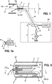
- a probe S comprises an axial electrode 1 and a peripheral electrode 2.
- the axial electrode 1 has an axis of symmetry AA, and is housed in a casing 3 which is electrically insulating.
- One end 1P of the axial electrode 1 is discovered outside the casing 3, to be in contact with a gas external to the probe S.
- the figure 1a shows a magnification of the exposed 1P end of the axial electrode 1.
- This exposed 1P end has a tip shape parallel to the AA axis, with a radius of curvature R1 which is less than 5 mm (millimeter), preferably less than 2 mm.
- Axial electrode 1 is in an electrically conductive material, preferably an alloy which is resistant to abrasion and atomic spray when exposed to plasma.
- the peripheral electrode 2 can have an annular shape also having the axis AA as the axis of symmetry. It is placed at a distance from the axial electrode 1, in particular radially relative to the axis AA.
- the peripheral electrode 2 is also made of a material which is electrically conductive, and has an exposed part 2P which is intended to be in contact with the gas external to the probe S at the same time as the axial electrode 1.
- the peripheral electrode 2 can be kept in a fixed position with respect to the axial electrode 1 by at least one arm 3 ', which is designed to little disturb, or disturb as little as possible an EC flow of the external gas around the probe S, possibly by allowing a passage of the gas between the casing 3 and the peripheral electrode 2.
- the arm 3 ' is also designed to electrically insulate the peripheral electrode 2 with respect to the axial electrode 1, while making it possible to connect electrically the peripheral electrode 2 to a power supply terminal of the probe S, as explained below.
- the axial electrode 1 can be made of tungsten (W), molybdenum (Mo) or stainless steel, and the peripheral electrode can be made of stainless steel or an aluminum alloy (Al).
- An electrical supply circuit 4 makes it possible to apply an electrical voltage between the axial electrode 1 and the peripheral electrode 2.
- the supply circuit 4 comprises a voltage supply source 5, and optionally a ballast resistor 6.
- a first output terminal of the power source 5, denoted HT for high voltage is connected to the axial electrode 1
- a second output terminal of the power source 5, denoted G is connected to the axial electrode 1.
- the terminal G can be connected to a ground of an AV support of the probe S.
- the probe S can be rigidly fixed to the AV support by means of a mast M, and the AV support can contain the electrical supply circuit 4.
- an electrical connection 10 connects the axial electrode 1 to the HT terminal of the power source.
- the AV support of the probe S can be an aircraft, for example an airplane, and the gas of the EC flow is the surrounding air around the airplane.
- the purpose of the probe S is then to make it possible to measure the speed of the air flow EC with respect to the support AV.
- the probe S is oriented with respect to the flow EC so that the axis AA is parallel to the flow, with the exposed end 1P of the axial electrode 1 which is oriented upstream of the flow. flow.
- the ballast resistor 6 can be between 1 megohm (M ⁇ ) and 100 M ⁇ , for example a few tens of megohms.
- the application of an electric potential difference between the two electrodes causes an electric field concentration at proximity to that of the electrodes which has the smallest radius of curvature.
- the electric field which is concentrated in front of the electrode with the smallest radius of curvature can exceed the gas breakdown threshold.
- An electric discharge then occurs through the gas, during which an electronic avalanche will ionize atoms and / or molecules of the gas, and thus form a plasma of positive charges, ie cations, and negative charges, ie especially electrons. .
- the properties of this electric discharge are determined by the nature of the gas, including its density, temperature, chemical composition, and the polarity of the electric voltage that is applied between the two electrodes.
- the topology and behavior of the electric discharge are very different depending on the polarity of the electric voltage that is applied.
- the electrode with the smallest radius of curvature is positively polarized, a positive corona discharge occurs, in the form of plasma filaments which propagate from that electrode which has the smallest radius of curvature.
- These plasma filaments which have distributions random spatial and temporal, produce electrical pulses in the closed circuit supplying the electrodes.
- Trichel electrical pulses When the electrode with the smaller radius of curvature is negatively polarized with respect to the other electrode, a negative corona discharge is obtained, as a regular or roughly regular series of Trichel electrical pulses. Each pulse corresponds to the formation of ionic species in the vicinity of the electrode with a small radius of curvature. The temporal distribution of these pulses is narrow and bounded by a maximum frequency. When the electric voltage which is applied between the two electrodes is below a lower threshold, the pulses are irregular. When the applied voltage exceeds a higher threshold, a quasi-continuous electric discharge regime appears.
- the frequency of the electric discharge pulses through the gas depends on the value of the electric voltage that is applied between the two electrodes, of the gas, including its electronegativity value and its rate of d humidity, the EC gas flow velocity, the electrode material with the smallest radius of curvature, its geometry, including its radius of curvature and surface roughness, and the ambient electric field.
- each electric discharge pulse through the gas proceeds by electronic avalanche, initiated in the zone where the electric field is maximum, that is to say near the electrode which has the smallest radius of curvature. .
- Such an avalanche begins with the formation of seed electrons at the tip of the electrode, by field-effect emission or by secondary emission which is caused by the impact of a cation on the electrode.
- these electrons are repelled from the tip electrode by the electric field emanating from it.
- they are accelerated and will collide with atoms or molecules of the gas. A part of these electrons which have enough energy will produce ionizing collisions which will each create an additional electron and an additional cation.
- an avalanche An exponential multiplication of the number of electrons, called an avalanche, is thus produced, as the electrons move away from the electrode with a small radius of curvature. This avalanche will then stop because of two phenomena. As the electron cloud moves away from the small radius of curvature electrode, the electric field that is created by this electrode decreases, consequently reducing the energy of the electrons at the time of further collisions. In addition, the formation of free electric charges in the gas produces an electrostatic screen which attenuates the electric field created by the small radius of curvature electrode.
- pulses of electric current appear in the electrical supply circuit 4, and therefore in the axial electrode 1 and the electrical connection 10, with a pulse frequency, or an average duration between two successive pulses, which depends on the velocity of the EC flow. More precisely, the duration between two successive pulses increases when the speed of the EC flow becomes greater, if the exposed tip 1P of the axial electrode 1 is oriented towards the upstream side of the EC flow.
- Such pulses are detected by induction, making it possible to prevent a continuity of an electrical path connecting the electrical supply circuit 4 to a circuit which is used to detect the negative corona discharge current.
- a detection circuit 7 comprises at least one conductive turn 8, or possibly several turns in the form of a detection coil, which surround (s) the electrical connection 10 and is (are) connected (s) to a counter d 'pulses 9, denoted COMPT. It is thus possible to count the electrical pulses which are induced in the coil 8 by induction by the electric discharge pulses which circulate in the electrical connection 10.
- the coil 8 can be produced in the form of a Rogowski coil. known to those skilled in the art.
- the detection and the counting of the pulses are limited according to the invention to the inside of the windows of time FN during which the electric potential of the axial electrode 1 is lower than that of the peripheral electrode 2.
- the time windows FN are contained in periods of time where the voltage which is delivered by the source 5 is negative. In the jargon of those skilled in the art, these periods of time are called negative alternations of the alternating electric voltage.
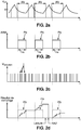
- the figure 2a shows the variations of the electric voltage, denoted V HT , which is delivered by the source 5 as a function of time, denoted t.
- V HT the electric voltage
- t the time
- a peak value of the voltage V HT can be between 1 kV (kilovolt) and 20 kV, and its frequency can be of the order of a few hundred hertz when the gas of the EC flow is air.
- AN designates the negative half-waves of the voltage V HT .
- the figure 2b shows a possible signal for the activation of the counting of the pulses which are detected by the circuit 7.
- This activation signal denoted ARM, authorizes the counting of the pulses within time windows FN, which are themselves contained in the negative half-waves AN of the voltage V HT .
- T FN designates the duration of each FN time window.
- the figure 2c is an example of the temporal distribution of the electrical pulses which are detected by circuit 7, denoted I. These pulses I occur both during positive half-waves as well as negative half-waves of voltage V HT , but only those of negative half-waves have a regularity sufficient to provide a reliable measurement of the EC flow velocity.
- the figure 2c represents for example the absolute value of the voltage which exists between the ends of the conductive coil 8, and which is denoted V detection .
- FIG. 2d shows the evolution of a counting result of the pulses I, when the counting is carried out continuously during two successive negative half-waves of the electric voltage V HT .
- the counting result is read after the end of the last FN time window of the counting duration, then a counting reset, denoted RAZ, is performed. before the start of a new FN time window for a new pulse count.
- the average duration T between two successive pulses which are detected is an increasing function of the speed U of the flow EC, when the probe S is oriented upstream of the flow EC as shown on the diagram.
- T FN is again the duration of a time window FN
- N is the number of I pulses which are counted during 1 time window FN.
- the sequence Calibration can be performed once initially, or be repeated several times between successive useful measurements when the speed U can be known using other methods. Such other methods can for example use GPS measurements, or an onboard sensor which is of a different type when the AV support is an airplane, in particular a Pitot type probe.
- the measurement dynamic of a device according to the invention can be controlled by the amplitude of the alternating voltage V HT which is applied between the electrodes 1 and 2.
- this dynamic is controlled by the average number of pulses I in each time window FN, itself being an increasing function of the alternating voltage V HT . It is thus possible to obtain a good sensitivity for low values of the speed U of the flow EC, for example of the order of ten meters-per-second, as well as for high values of the flow. speed U, for example of the order of several hundred meters per second.
- An additional advantage of the invention results from the digital nature of the measurement signal which is acquired, as opposed to an analog measurement which can be sensitive to electromagnetic disturbances.
- the figure 3 shows an alternative embodiment of a speed measuring device according to the invention.
- the peripheral electrode 2 is arranged on the outer surface of the insulating casing 3, set back downstream of the flow EC of the gas relative to the end 1P of the axial electrode 1.
- the ballast resistor 6 can be housed in the probe S, and be formed by a cylinder of material with low electrical conduction, which surrounds a rear part of the axial electrode 1, opposite to its exposed end 1P. This cylinder can be in electrical contact with the rear part of the axial electrode 1, and can itself be connected from its rear end, to the electrical connection 10 which comes from the source 5.
- a tube 11 of electrically conductive material may be disposed around the cylinder of the ballast resistor 6, with a layer 12 of electrically insulating material which is intermediate between the cylinder of the ballast resistor 6 and tube 11. Tube 11 is then electrically connected to ground G. In this way, the cylinder of ballast resistor 6 and tube 11 form a cylindrical capacitor.
- the heating power of the axial electrode 1 can then be adjusted by modifying the frequency or the form of the temporal variations of the alternating voltage V HT , in particular by modifying the slope of the rising edges of this alternating voltage without modifying the duration of the windows of FN times which are dedicated to counting pulses I. Indeed, the current flowing through the capacitor formed by the cylinder of the ballast resistor 6 and by the tube 11, can be modified in this way to vary the heating power of the 'axial electrode 1.
- Such a method of heating the axial electrode 1 is independent of the existence and the average intensity of the electric discharge current which flows in the electrode 1, through the gas, and in the gas. electrode 2.
- the material of the cylinder of the ballast resistor 6 may be a conductive resin or carbon graphite (C), and the tube 11 may be an aluminum alloy (Al) or a conductive metal.
- the intermediate layer 12 can be made of a polymeric material, such as polytetrafluoroethylene (PTFE), Mylar®, Kapton®, or be made of an insulating ceramic whose breakdown voltage is greater than the maximum absolute value of the voltage V HT , and the casing 3 can be made of polymer material or ceramic.
- the coil 8 of the detection circuit 7 can be arranged around the axial electrode 1, inside the casing 3 between the uncovered end 1P of the axial electrode 1 and the front end of the cylinder of the resistor ballast 6. Thanks to such an arrangement, the detection of the electric discharge through the gas is not disturbed by the current which is used to possibly heat the axial electrode 1.
- the probe S may have the shape of a cylinder approximately one centimeter in diameter and a few centimeters in length.
- the pulse counter of the detection circuit can be implemented in multiple ways, with or without incorporating an integrator.
- the alternating electric voltage which is applied between the two electrodes is not necessarily sinusoidal.
Landscapes
- Physics & Mathematics (AREA)
- General Physics & Mathematics (AREA)
- Engineering & Computer Science (AREA)
- Aviation & Aerospace Engineering (AREA)
- Fluid Mechanics (AREA)
- Other Investigation Or Analysis Of Materials By Electrical Means (AREA)
- Measuring Volume Flow (AREA)
- Indicating Or Recording The Presence, Absence, Or Direction Of Movement (AREA)
Claims (15)
- Messvorrichtung einer Geschwindigkeit einer Gasströmung, die enthält:- eine starre Sonde (S), die dazu bestimmt ist, in der Gasströmung (EC) platziert zu werden, wobei die Sonde eine axiale Elektrode (1) enthält, die ein unbedecktes Ende (1P) aufweist, das dazu bestimmt ist, mit dem Gas in Kontakt zu sein, wobei das unbedeckte Ende einen Krümmungsradius (R1) hat, der geeignet ist, eine Verstärkung der elektrischen Feldstärke durch Spitzenwirkung zu produzieren, und eine Umfangselektrode (2) enthält, die elektrisch von der axialen Elektrode isoliert ist, und die einen unbedeckten Teil (2P) besitzt, der auch dazu bestimmt ist, mit dem Gas in Kontakt zu sein, der sich in Abstand zur axialen Elektrode befindet; und- eine Versorgungsquelle (5) mit elektrischer Spannung, die zwei Ausgangsanschlüsse (HT, G) hat, die elektrisch der eine mit der axialen Elektrode (1) und der andere mit der Umfangselektrode (2) verbunden sind;dadurch gekennzeichnet, dass die Versorgungsquelle (5) eine elektrische Wechselspannung (AC) produziert, und dass die Vorrichtung außerdem enthält:- eine Erfassungsschaltung (7), die mindestens eine leitende Windung (8) enthält, die um eine elektrische Verbindung (10) herum angeordnet ist, die eine der Elektroden (1, 2) der Sonde (S) mit einem der Anschlüsse der Versorgungsquelle (5) verbindet, oder um die axiale Elektrode (1) herum angeordnet ist, und einen Zähler (9) enthält, der eingerichtet ist, um elektrische Impulse (I) zu zählen, die in der leitenden Windung durch Induktion erzeugt werden, selektiv während mindestens eines Zeitfensters (FN), während dessen ein erstes elektrisches Potential der axialen Elektrode (1) niedriger ist als ein elektrisches Potential der Umfangselektrode (2),so dass, wenn die Sonde (S) durch die Versorgungsquelle (5) mit der elektrischen Wechselspannung (AC) versorgt wird, eine Anzahl von elektrischen Impulsen (I), die von der Erfassungsschaltung (7) gezählt werden, entsprechend einer Anzahl von elektrischen Entladungen, die zwischen der axialen Elektrode (1) und der Umfangselektrode (2) durch das Gas hindurch aufgetreten sind, einen Messwert der Geschwindigkeit der Strömung (EC) des Gases bildet.
- Vorrichtung nach Anspruch 1, wobei der unbedeckte Teil (2P) der Umfangselektrode (2) eine Ringform um eine Symmetrieachse (A-A) des unbedeckten Endes (1P) der axialen Elektrode (1) besitzt.
- Vorrichtung nach Anspruch 1 oder 2, wobei der unbedeckte Teil (2P) der Umfangselektrode (2) bezüglich des unbedeckten Endes (1P) der axialen Elektrode (1) eingerückt ist, mit einer Einrückrichtung, die dem unbedeckten Ende der axialen Elektrode entgegengesetzt ist.
- Vorrichtung nach einem der vorhergehenden Ansprüche, die außerdem einen Ballastwiderstand (6) enthält, der zwischen einer der Elektroden (1, 2) der Sonde (S) und dem Anschluss der Versorgungsquelle (5), der mit der Elektrode verbunden ist, in Reihe geschaltet ist, und der Ballastwiderstand ist in der Sonde eingerichtet.
- Vorrichtung nach Anspruch 4, wobei der Ballastwiderstand (6) in der Sonde (S) um ein hinteres Ende der axialen Elektrode (1) entgegengesetzt zum unbedeckten Ende (1P) der axialen Elektrode angeordnet ist, und mit einer Umfangsfläche des hinteren Endes der axialen Elektrode in elektrischem Kontakt ist.
- Vorrichtung nach Anspruch 5, wobei der Ballastwiderstand (6) von einem Zylinder aus elektrisch leitendem Werkstoff gebildet wird, und die Sonde (S) außerdem ein elektrisch leitendes Rohr (11) enthält, das angeordnet und elektrisch verbunden ist, um mit dem Zylinder des Ballastwiderstands einen Kondensator zu bilden, so dass ein elektrischer Strom, der im Kondensator fließt, wenn die Sonde von der Versorgungsquelle (5) versorgt wird, durch Joule-Effekt im Zylinder des Ballastwiderstands Wärme erzeugt, die die axiale Elektrode (1) erwärmen kann.
- Vorrichtung nach Anspruch 6, wobei die leitende Windung (8) in der Sonde (S) um einen Teil der axialen Elektrode (1) angeordnet ist, der nicht vom Zylinder des Ballastwiderstands (6) bedeckt wird, indem sie elektrisch von der axialen Elektrode isoliert ist.
- Verfahren zur Messung einer Geschwindigkeit einer Gasströmung (EC), das enthält:/1/ Bereitstellen einer starren Sonde (S), die eine axiale Elektrode (1) enthält, die ein unbedecktes Ende (1P) mit einem Krümmungsradius (R1) aufweist, der geeignet ist, eine Verstärkung einer elektrischen Feldstärke durch Spitzenwirkung zu produzieren, und eine Umfangselektrode (2) enthält, die elektrisch von der axialen Elektrode isoliert ist, und die einen unbedeckten Teil (2P) besitzt, der sich in Abstand zur axialen Elektrode befindet;/2/ Platzieren der Sonde (S) in der Gasströmung (EC), so dass das unbedeckte Ende (1P) der axialen Elektrode (1) und der unbedeckte Teil (2P) der Umfangselektrode (2) gleichzeitig mit dem Gas in Kontakt sind; und/3/ Anlegen einer elektrischen Spannung zwischen der axialen Elektrode (1) und der Umfangselektrode (2), um elektrische Entladungen zwischen den Elektroden durch das Gas hindurch zu produzieren;dadurch gekennzeichnet, dass die elektrische Spannung, die angelegt wird, eine elektrische Wechselspannung (AC) ist, und dass das Verfahren außerdem die folgenden Schritte enthält:/4/ Erfassen und Zählen von elektrischen Impulsen (I), die durch Induktion in mindestens einer leitenden Windung (8) erzeugt werden, die um eine elektrische Verbindung (10) herum angeordnet ist, die verwendet wird, um die Wechselspannung (AC) an die Elektroden (1, 2) anzulegen, oder um die axiale Elektrode (1) herum angeordnet ist, und die elektrischen Entladungen durch das Gas hindurch entsprechen, selektiv während mindestens eines Zeitfensters (FN), während dessen ein elektrisches Potential der axialen Elektrode (1) niedriger ist als ein elektrisches Potential der Umfangselektrode (2); und/5/ Ableiten eines Werts der Geschwindigkeit der Strömung (EC) des Gases ausgehend von einem Zählergebnis der elektrischen Impulse (I).
- Verfahren nach Anspruch 8, gemäß dem die Sonde (S) bezüglich der Gasströmung (EC) so ausgerichtet ist, dass das unbedeckte Ende (1P) der axialen Elektrode (1) zu einer stromaufwärtigen Richtung der Strömung weist, und dass eine Symmetrieachse (A-A) des unbedeckten Endes (1P) der axialen Elektrode (1) parallel zur Gasströmung ist.
- Verfahren nach Anspruch 8 oder 9, gemäß dem das Zählen der elektrischen Impulse (I) während mehrerer aufeinanderfolgender Zeitfenster (FN) fortgesetzt wird, wobei jedes Zeitfenster in einer negativen Halbwelle (AN) des elektrischen Potentials der axialen Elektrode (1) bezüglich des elektrischen Potentials der Umfangselektrode (2) enthalten ist, getrennt von jedem anderen Zeitfenster.
- Verfahren nach einem der Ansprüche 8 bis 10, gemäß dem eine mittlere Dauer zwischen zwei elektrischen Impulsen (I), die innerhalb eines Zeitfensters (FN) aufeinander folgen, oder eine mittlere Frequenz der elektrischen Impulse innerhalb eines Zeitfensters berechnet wird, und der Wert der Strömungsgeschwindigkeit (EC) des Gases von der mittleren Dauer oder der mittleren Frequenz abgeleitet wird.
- Verfahren nach einem der Ansprüche 8 bis 11, gemäß dem die Geschwindigkeit der Gasströmung (EC) unter Verwendung der Formel U = U1·(N0 - N)/(N0 - N1) berechnet wird, wobei N0 eine erste Anzahl elektrischer Impulse (I) ist, die für eine erste Kalibriermessung gezählt werden, die ausgeführt wird, wenn die Geschwindigkeit der Gasströmung Null ist, N1 eine zweite Anzahl elektrischer Impulse ist, die für eine zweite Kalibriermessung gezählt werden, die ausgeführt wird, wenn die Geschwindigkeit der Gasströmung ungleich Null und gleich U1 ist, N eine dritte Anzahl elektrischer Impulse ist, die für eine Nutzmessung gezählt, und U ein Wert der Geschwindigkeit der Gasströmung während der Nutzmessung ist, wobei die zwischen den zwei Elektroden (1, 2) der Sonde (S) angelegte elektrische Wechselspannung (AC) für die erste und zweite Kalibriermessung und für die Nutzmessung gleich ist.
- Verfahren nach einem der Ansprüche 8 bis 12, das unter Verwendung einer Vorrichtung nach Anspruch 6 oder 7 durchgeführt wird, und gemäß dem eine Heizleistung, die im Ballastwiderstand (6) abgestrahlt wird, eingestellt wird, indem eine Frequenz oder eine Form der elektrischen Wechselspannung (AC) verändert wird, die von der Versorgungsquelle (5) produziert wird.
- Verfahren nach einem der Ansprüche 8 bis 13, durchgeführt an Bord eines Luftfahrzeugs (AV), das geeignet ist, sich bezüglich der Luft außerhalb des Luftfahrzeugs zu bewegen, wobei die Sonde (S) starr am Luftfahrzeug befestigt ist, um in der Strömung (EC) der Luft außerhalb des Luftfahrzeugs gehalten zu werden.
- Verfahren nach Anspruch 14, wobei die Umfangselektrode (2) der Sonde (S) elektrisch mit einer Masse (G) des Luftfahrzeugs (AV) verbunden ist, so dass ein elektrisches Potential der Umfangselektrode konstant gleich einem elektrischen Potential der Masse des Luftfahrzeugs ist.
Applications Claiming Priority (2)
| Application Number | Priority Date | Filing Date | Title |
|---|---|---|---|
| FR1662169A FR3060125B1 (fr) | 2016-12-08 | 2016-12-08 | Dispositif et procede de mesure d'une vitesse d'ecoulement de gaz |
| PCT/FR2017/053343 WO2018104627A1 (fr) | 2016-12-08 | 2017-12-01 | Dispositif et procede de mesure d'une vitesse d'ecoulement de gaz |
Publications (2)
| Publication Number | Publication Date |
|---|---|
| EP3552026A1 EP3552026A1 (de) | 2019-10-16 |
| EP3552026B1 true EP3552026B1 (de) | 2021-01-27 |
Family
ID=58228217
Family Applications (1)
| Application Number | Title | Priority Date | Filing Date |
|---|---|---|---|
| EP17821676.8A Active EP3552026B1 (de) | 2016-12-08 | 2017-12-01 | Vorrichtung und verfahren zum messen der gasflussrate |
Country Status (8)
| Country | Link |
|---|---|
| US (1) | US11035705B2 (de) |
| EP (1) | EP3552026B1 (de) |
| JP (1) | JP6942802B2 (de) |
| CN (1) | CN110062888B (de) |
| CA (1) | CA3045570C (de) |
| ES (1) | ES2865852T3 (de) |
| FR (1) | FR3060125B1 (de) |
| WO (1) | WO2018104627A1 (de) |
Families Citing this family (7)
| Publication number | Priority date | Publication date | Assignee | Title |
|---|---|---|---|---|
| CN110221094B (zh) * | 2019-07-16 | 2021-05-04 | 深圳市锐进微电子有限公司 | 气流检测电路及装置 |
| US11332260B2 (en) * | 2019-11-18 | 2022-05-17 | The Boeing Company | Electrode-arc sensor air data system for an aircraft |
| CN111308122B (zh) * | 2019-12-06 | 2022-02-25 | 云南师范大学 | 基于掺硼硅量子点的气体流速探测器及系统 |
| CN111812354B (zh) * | 2020-06-16 | 2021-12-03 | 天津大学 | 一种基于高压放电的流场速度测量系统 |
| CN113009178B (zh) * | 2021-02-18 | 2022-08-09 | 上海交通大学 | 一种基于滑移电弧的流速测量系统 |
| US12085428B2 (en) * | 2021-09-14 | 2024-09-10 | Pratt & Whitney Canada Corp. | Methods and devices for measuring mass flow of gaseous fluids |
| CN115436012B (zh) * | 2022-07-26 | 2025-10-31 | 中国科学院国家空间科学中心 | 一种测量自由分子流空间分布的装置及方法 |
Family Cites Families (8)
| Publication number | Priority date | Publication date | Assignee | Title |
|---|---|---|---|---|
| US3945251A (en) * | 1974-10-11 | 1976-03-23 | Stanford Research Institute | Trichel pulse corona gas velocity instrument |
| US4127029A (en) | 1977-04-25 | 1978-11-28 | La General De Fluides Geflu | Ionic measuring device |
| FR2491618B1 (fr) | 1980-10-07 | 1985-06-07 | Renault | Capteur ionique de debit a temps de transit de type differentiel |
| JP3763225B2 (ja) * | 1999-01-20 | 2006-04-05 | 富士電機ホールディングス株式会社 | イオンドリフト式流量計 |
| AT501993B1 (de) | 2006-02-20 | 2007-06-15 | Guenter Dipl Ing Fh Weilguny | Vorrichtung für die messung der geschwindigkeit eines fluids |
| US20120173191A1 (en) * | 2011-01-03 | 2012-07-05 | Moeller Lothar B | Airspeed And Velocity Of Air Measurement |
| US9433071B2 (en) * | 2014-06-13 | 2016-08-30 | Plasma Innovations, LLC | Dielectric barrier discharge plasma generator |
| CN105716788B (zh) * | 2015-11-02 | 2019-02-22 | 北京航空航天大学 | 三孔跨音速压力探针 |
-
2016
- 2016-12-08 FR FR1662169A patent/FR3060125B1/fr not_active Expired - Fee Related
-
2017
- 2017-12-01 WO PCT/FR2017/053343 patent/WO2018104627A1/fr not_active Ceased
- 2017-12-01 EP EP17821676.8A patent/EP3552026B1/de active Active
- 2017-12-01 ES ES17821676T patent/ES2865852T3/es active Active
- 2017-12-01 JP JP2019531049A patent/JP6942802B2/ja active Active
- 2017-12-01 CA CA3045570A patent/CA3045570C/fr active Active
- 2017-12-01 CN CN201780075863.7A patent/CN110062888B/zh active Active
- 2017-12-01 US US16/467,938 patent/US11035705B2/en active Active
Non-Patent Citations (1)
| Title |
|---|
| None * |
Also Published As
| Publication number | Publication date |
|---|---|
| CA3045570A1 (fr) | 2018-06-14 |
| CN110062888B (zh) | 2021-09-24 |
| EP3552026A1 (de) | 2019-10-16 |
| JP2020513559A (ja) | 2020-05-14 |
| CN110062888A (zh) | 2019-07-26 |
| FR3060125A1 (fr) | 2018-06-15 |
| FR3060125B1 (fr) | 2018-12-07 |
| US11035705B2 (en) | 2021-06-15 |
| JP6942802B2 (ja) | 2021-09-29 |
| CA3045570C (fr) | 2025-05-27 |
| WO2018104627A1 (fr) | 2018-06-14 |
| ES2865852T3 (es) | 2021-10-18 |
| US20190346298A1 (en) | 2019-11-14 |
Similar Documents
| Publication | Publication Date | Title |
|---|---|---|
| EP3552026B1 (de) | Vorrichtung und verfahren zum messen der gasflussrate | |
| EP0792571B1 (de) | Verfahren und vorrichtung zur messung eines zonenflusses in einem plasma | |
| EP0192000B1 (de) | Blitzableiter mit periodischer Corona-Stossentladung | |
| EP0051006A2 (de) | Verfahren und Vorrichtungen zum Übertragen elektrischer Ladungen verschiedener Zeichen in ein Raumgebiet und Verwendung in Vorrichtungen zum Beseitigen statischer Elektrizität | |
| Fognini et al. | Ultrafast reduction of the total magnetization in iron | |
| FR2875304A1 (fr) | Sonde de mesure de caracteristiques d'un courant d'excitation d'un plasma, et reacteur a plasma associe | |
| WO2015181383A1 (fr) | Dispositif de détection de courant | |
| EP3098830B1 (de) | Überwachungsvorrichtung der teilentladungen eines stromnetzes | |
| EP3061117B1 (de) | Röntgenstrahlgenerator mit eingebautem durchflusssensor | |
| Liu et al. | Ultrafast ultraviolet laser-induced voltage of air | |
| EP3086140B1 (de) | Kugelförmige erkennungsvorrichtung von partikeln oder strahlung | |
| RU2699930C1 (ru) | Быстродействующий фотодетектор | |
| EP0116806A1 (de) | Gekrümmter Elektronenlawinen-Gasdetektor mit plättchenförmiger Elektrode | |
| Suryanarayana et al. | Study of propagation of ion acoustic waves in argon plasma | |
| EP2409132A1 (de) | Verfahren zur bestimmung des oberflächenradius und/oder der teilchendichte eines pulvers | |
| WO2014016473A1 (fr) | Détecteur de fumée | |
| FR2602058A1 (fr) | Detecteur a gaz utilisant une anode a microbandes | |
| FR2583167A1 (fr) | Appareil electrostatique pour la mesure des caracteristiques d'ionisation d'un milieu gazeux | |
| WO1998042475A1 (fr) | Procede pour le controle d'un processus d'ablation laser, applications d'un tel procede et equipement pour la mise en oeuvre de ce procede | |
| FR2971354A1 (fr) | Detecteur de fumee | |
| Brand et al. | Preionization and shock-wave ionization in a crossed-field plasma source | |
| FR2981499A1 (fr) | Sonde a champs croises pour la detection d'ions positifs et negatifs. | |
| FR2573218A1 (fr) | Appareil electrique de detection et caracterisation de couches faiblement conductrices posees ou deposees sur un substrat conducteur de l'electricite | |
| Costin et al. | Electrical probe characteristic recovery by measuring only one time-dependent parameter | |
| Bletzinger et al. | Mutual interactions between low Mach number shock waves and nonequilibrium plasmas |
Legal Events
| Date | Code | Title | Description |
|---|---|---|---|
| STAA | Information on the status of an ep patent application or granted ep patent |
Free format text: STATUS: UNKNOWN |
|
| STAA | Information on the status of an ep patent application or granted ep patent |
Free format text: STATUS: THE INTERNATIONAL PUBLICATION HAS BEEN MADE |
|
| PUAI | Public reference made under article 153(3) epc to a published international application that has entered the european phase |
Free format text: ORIGINAL CODE: 0009012 |
|
| STAA | Information on the status of an ep patent application or granted ep patent |
Free format text: STATUS: REQUEST FOR EXAMINATION WAS MADE |
|
| 17P | Request for examination filed |
Effective date: 20190412 |
|
| AK | Designated contracting states |
Kind code of ref document: A1 Designated state(s): AL AT BE BG CH CY CZ DE DK EE ES FI FR GB GR HR HU IE IS IT LI LT LU LV MC MK MT NL NO PL PT RO RS SE SI SK SM TR |
|
| AX | Request for extension of the european patent |
Extension state: BA ME |
|
| DAV | Request for validation of the european patent (deleted) | ||
| DAX | Request for extension of the european patent (deleted) | ||
| RIC1 | Information provided on ipc code assigned before grant |
Ipc: G01P 5/08 20060101AFI20200818BHEP Ipc: G01F 1/56 20060101ALI20200818BHEP |
|
| GRAP | Despatch of communication of intention to grant a patent |
Free format text: ORIGINAL CODE: EPIDOSNIGR1 |
|
| STAA | Information on the status of an ep patent application or granted ep patent |
Free format text: STATUS: GRANT OF PATENT IS INTENDED |
|
| INTG | Intention to grant announced |
Effective date: 20200929 |
|
| GRAS | Grant fee paid |
Free format text: ORIGINAL CODE: EPIDOSNIGR3 |
|
| GRAA | (expected) grant |
Free format text: ORIGINAL CODE: 0009210 |
|
| STAA | Information on the status of an ep patent application or granted ep patent |
Free format text: STATUS: THE PATENT HAS BEEN GRANTED |
|
| AK | Designated contracting states |
Kind code of ref document: B1 Designated state(s): AL AT BE BG CH CY CZ DE DK EE ES FI FR GB GR HR HU IE IS IT LI LT LU LV MC MK MT NL NO PL PT RO RS SE SI SK SM TR |
|
| REG | Reference to a national code |
Ref country code: GB Ref legal event code: FG4D Free format text: NOT ENGLISH |
|
| REG | Reference to a national code |
Ref country code: CH Ref legal event code: EP |
|
| REG | Reference to a national code |
Ref country code: AT Ref legal event code: REF Ref document number: 1358842 Country of ref document: AT Kind code of ref document: T Effective date: 20210215 |
|
| REG | Reference to a national code |
Ref country code: IE Ref legal event code: FG4D Free format text: LANGUAGE OF EP DOCUMENT: FRENCH |
|
| REG | Reference to a national code |
Ref country code: DE Ref legal event code: R096 Ref document number: 602017032216 Country of ref document: DE |
|
| REG | Reference to a national code |
Ref country code: NL Ref legal event code: MP Effective date: 20210127 |
|
| REG | Reference to a national code |
Ref country code: LT Ref legal event code: MG9D |
|
| REG | Reference to a national code |
Ref country code: AT Ref legal event code: MK05 Ref document number: 1358842 Country of ref document: AT Kind code of ref document: T Effective date: 20210127 |
|
| PG25 | Lapsed in a contracting state [announced via postgrant information from national office to epo] |
Ref country code: LT Free format text: LAPSE BECAUSE OF FAILURE TO SUBMIT A TRANSLATION OF THE DESCRIPTION OR TO PAY THE FEE WITHIN THE PRESCRIBED TIME-LIMIT Effective date: 20210127 Ref country code: BG Free format text: LAPSE BECAUSE OF FAILURE TO SUBMIT A TRANSLATION OF THE DESCRIPTION OR TO PAY THE FEE WITHIN THE PRESCRIBED TIME-LIMIT Effective date: 20210427 Ref country code: FI Free format text: LAPSE BECAUSE OF FAILURE TO SUBMIT A TRANSLATION OF THE DESCRIPTION OR TO PAY THE FEE WITHIN THE PRESCRIBED TIME-LIMIT Effective date: 20210127 Ref country code: HR Free format text: LAPSE BECAUSE OF FAILURE TO SUBMIT A TRANSLATION OF THE DESCRIPTION OR TO PAY THE FEE WITHIN THE PRESCRIBED TIME-LIMIT Effective date: 20210127 Ref country code: GR Free format text: LAPSE BECAUSE OF FAILURE TO SUBMIT A TRANSLATION OF THE DESCRIPTION OR TO PAY THE FEE WITHIN THE PRESCRIBED TIME-LIMIT Effective date: 20210428 Ref country code: NO Free format text: LAPSE BECAUSE OF FAILURE TO SUBMIT A TRANSLATION OF THE DESCRIPTION OR TO PAY THE FEE WITHIN THE PRESCRIBED TIME-LIMIT Effective date: 20210427 Ref country code: PT Free format text: LAPSE BECAUSE OF FAILURE TO SUBMIT A TRANSLATION OF THE DESCRIPTION OR TO PAY THE FEE WITHIN THE PRESCRIBED TIME-LIMIT Effective date: 20210527 |
|
| PG25 | Lapsed in a contracting state [announced via postgrant information from national office to epo] |
Ref country code: RS Free format text: LAPSE BECAUSE OF FAILURE TO SUBMIT A TRANSLATION OF THE DESCRIPTION OR TO PAY THE FEE WITHIN THE PRESCRIBED TIME-LIMIT Effective date: 20210127 Ref country code: PL Free format text: LAPSE BECAUSE OF FAILURE TO SUBMIT A TRANSLATION OF THE DESCRIPTION OR TO PAY THE FEE WITHIN THE PRESCRIBED TIME-LIMIT Effective date: 20210127 Ref country code: LV Free format text: LAPSE BECAUSE OF FAILURE TO SUBMIT A TRANSLATION OF THE DESCRIPTION OR TO PAY THE FEE WITHIN THE PRESCRIBED TIME-LIMIT Effective date: 20210127 Ref country code: AT Free format text: LAPSE BECAUSE OF FAILURE TO SUBMIT A TRANSLATION OF THE DESCRIPTION OR TO PAY THE FEE WITHIN THE PRESCRIBED TIME-LIMIT Effective date: 20210127 Ref country code: SE Free format text: LAPSE BECAUSE OF FAILURE TO SUBMIT A TRANSLATION OF THE DESCRIPTION OR TO PAY THE FEE WITHIN THE PRESCRIBED TIME-LIMIT Effective date: 20210127 |
|
| PG25 | Lapsed in a contracting state [announced via postgrant information from national office to epo] |
Ref country code: IS Free format text: LAPSE BECAUSE OF FAILURE TO SUBMIT A TRANSLATION OF THE DESCRIPTION OR TO PAY THE FEE WITHIN THE PRESCRIBED TIME-LIMIT Effective date: 20210527 |
|
| REG | Reference to a national code |
Ref country code: ES Ref legal event code: FG2A Ref document number: 2865852 Country of ref document: ES Kind code of ref document: T3 Effective date: 20211018 |
|
| REG | Reference to a national code |
Ref country code: DE Ref legal event code: R097 Ref document number: 602017032216 Country of ref document: DE |
|
| PG25 | Lapsed in a contracting state [announced via postgrant information from national office to epo] |
Ref country code: SM Free format text: LAPSE BECAUSE OF FAILURE TO SUBMIT A TRANSLATION OF THE DESCRIPTION OR TO PAY THE FEE WITHIN THE PRESCRIBED TIME-LIMIT Effective date: 20210127 Ref country code: EE Free format text: LAPSE BECAUSE OF FAILURE TO SUBMIT A TRANSLATION OF THE DESCRIPTION OR TO PAY THE FEE WITHIN THE PRESCRIBED TIME-LIMIT Effective date: 20210127 Ref country code: CZ Free format text: LAPSE BECAUSE OF FAILURE TO SUBMIT A TRANSLATION OF THE DESCRIPTION OR TO PAY THE FEE WITHIN THE PRESCRIBED TIME-LIMIT Effective date: 20210127 |
|
| PG25 | Lapsed in a contracting state [announced via postgrant information from national office to epo] |
Ref country code: RO Free format text: LAPSE BECAUSE OF FAILURE TO SUBMIT A TRANSLATION OF THE DESCRIPTION OR TO PAY THE FEE WITHIN THE PRESCRIBED TIME-LIMIT Effective date: 20210127 Ref country code: DK Free format text: LAPSE BECAUSE OF FAILURE TO SUBMIT A TRANSLATION OF THE DESCRIPTION OR TO PAY THE FEE WITHIN THE PRESCRIBED TIME-LIMIT Effective date: 20210127 Ref country code: SK Free format text: LAPSE BECAUSE OF FAILURE TO SUBMIT A TRANSLATION OF THE DESCRIPTION OR TO PAY THE FEE WITHIN THE PRESCRIBED TIME-LIMIT Effective date: 20210127 |
|
| PLBE | No opposition filed within time limit |
Free format text: ORIGINAL CODE: 0009261 |
|
| STAA | Information on the status of an ep patent application or granted ep patent |
Free format text: STATUS: NO OPPOSITION FILED WITHIN TIME LIMIT |
|
| 26N | No opposition filed |
Effective date: 20211028 |
|
| PG25 | Lapsed in a contracting state [announced via postgrant information from national office to epo] |
Ref country code: AL Free format text: LAPSE BECAUSE OF FAILURE TO SUBMIT A TRANSLATION OF THE DESCRIPTION OR TO PAY THE FEE WITHIN THE PRESCRIBED TIME-LIMIT Effective date: 20210127 |
|
| PG25 | Lapsed in a contracting state [announced via postgrant information from national office to epo] |
Ref country code: SI Free format text: LAPSE BECAUSE OF FAILURE TO SUBMIT A TRANSLATION OF THE DESCRIPTION OR TO PAY THE FEE WITHIN THE PRESCRIBED TIME-LIMIT Effective date: 20210127 |
|
| PG25 | Lapsed in a contracting state [announced via postgrant information from national office to epo] |
Ref country code: IS Free format text: LAPSE BECAUSE OF FAILURE TO SUBMIT A TRANSLATION OF THE DESCRIPTION OR TO PAY THE FEE WITHIN THE PRESCRIBED TIME-LIMIT Effective date: 20210527 |
|
| PG25 | Lapsed in a contracting state [announced via postgrant information from national office to epo] |
Ref country code: MC Free format text: LAPSE BECAUSE OF FAILURE TO SUBMIT A TRANSLATION OF THE DESCRIPTION OR TO PAY THE FEE WITHIN THE PRESCRIBED TIME-LIMIT Effective date: 20210127 |
|
| REG | Reference to a national code |
Ref country code: CH Ref legal event code: PL |
|
| REG | Reference to a national code |
Ref country code: BE Ref legal event code: MM Effective date: 20211231 |
|
| PG25 | Lapsed in a contracting state [announced via postgrant information from national office to epo] |
Ref country code: LU Free format text: LAPSE BECAUSE OF NON-PAYMENT OF DUE FEES Effective date: 20211201 Ref country code: IE Free format text: LAPSE BECAUSE OF NON-PAYMENT OF DUE FEES Effective date: 20211201 |
|
| PG25 | Lapsed in a contracting state [announced via postgrant information from national office to epo] |
Ref country code: BE Free format text: LAPSE BECAUSE OF NON-PAYMENT OF DUE FEES Effective date: 20211231 |
|
| PG25 | Lapsed in a contracting state [announced via postgrant information from national office to epo] |
Ref country code: LI Free format text: LAPSE BECAUSE OF NON-PAYMENT OF DUE FEES Effective date: 20211231 Ref country code: CH Free format text: LAPSE BECAUSE OF NON-PAYMENT OF DUE FEES Effective date: 20211231 |
|
| PG25 | Lapsed in a contracting state [announced via postgrant information from national office to epo] |
Ref country code: NL Free format text: LAPSE BECAUSE OF NON-PAYMENT OF DUE FEES Effective date: 20210127 Ref country code: CY Free format text: LAPSE BECAUSE OF FAILURE TO SUBMIT A TRANSLATION OF THE DESCRIPTION OR TO PAY THE FEE WITHIN THE PRESCRIBED TIME-LIMIT Effective date: 20210127 |
|
| PG25 | Lapsed in a contracting state [announced via postgrant information from national office to epo] |
Ref country code: HU Free format text: LAPSE BECAUSE OF FAILURE TO SUBMIT A TRANSLATION OF THE DESCRIPTION OR TO PAY THE FEE WITHIN THE PRESCRIBED TIME-LIMIT; INVALID AB INITIO Effective date: 20171201 |
|
| PG25 | Lapsed in a contracting state [announced via postgrant information from national office to epo] |
Ref country code: MK Free format text: LAPSE BECAUSE OF FAILURE TO SUBMIT A TRANSLATION OF THE DESCRIPTION OR TO PAY THE FEE WITHIN THE PRESCRIBED TIME-LIMIT Effective date: 20210127 |
|
| PG25 | Lapsed in a contracting state [announced via postgrant information from national office to epo] |
Ref country code: TR Free format text: LAPSE BECAUSE OF FAILURE TO SUBMIT A TRANSLATION OF THE DESCRIPTION OR TO PAY THE FEE WITHIN THE PRESCRIBED TIME-LIMIT Effective date: 20210127 |
|
| PG25 | Lapsed in a contracting state [announced via postgrant information from national office to epo] |
Ref country code: MT Free format text: LAPSE BECAUSE OF FAILURE TO SUBMIT A TRANSLATION OF THE DESCRIPTION OR TO PAY THE FEE WITHIN THE PRESCRIBED TIME-LIMIT Effective date: 20210127 |
|
| PGFP | Annual fee paid to national office [announced via postgrant information from national office to epo] |
Ref country code: GB Payment date: 20251229 Year of fee payment: 9 |
|
| PGFP | Annual fee paid to national office [announced via postgrant information from national office to epo] |
Ref country code: FR Payment date: 20251230 Year of fee payment: 9 |
|
| PGFP | Annual fee paid to national office [announced via postgrant information from national office to epo] |
Ref country code: ES Payment date: 20260203 Year of fee payment: 9 |
|
| PGFP | Annual fee paid to national office [announced via postgrant information from national office to epo] |
Ref country code: DE Payment date: 20260127 Year of fee payment: 9 |
|
| PGFP | Annual fee paid to national office [announced via postgrant information from national office to epo] |
Ref country code: IT Payment date: 20251224 Year of fee payment: 9 |