EP3552073B1 - Reglerventil für enthäuter - Google Patents
Reglerventil für enthäuter Download PDFInfo
- Publication number
- EP3552073B1 EP3552073B1 EP17878881.6A EP17878881A EP3552073B1 EP 3552073 B1 EP3552073 B1 EP 3552073B1 EP 17878881 A EP17878881 A EP 17878881A EP 3552073 B1 EP3552073 B1 EP 3552073B1
- Authority
- EP
- European Patent Office
- Prior art keywords
- air
- regulator
- valve
- flow
- housing
- Prior art date
- Legal status (The legal status is an assumption and is not a legal conclusion. Google has not performed a legal analysis and makes no representation as to the accuracy of the status listed.)
- Active
Links
Images

Classifications
-
- A—HUMAN NECESSITIES
- A22—BUTCHERING; MEAT TREATMENT; PROCESSING POULTRY OR FISH
- A22B—SLAUGHTERING
- A22B5/00—Accessories for use during or after slaughtering
- A22B5/16—Skinning instruments or knives
- A22B5/163—Skinning knives with disc-shaped blades
-
- A—HUMAN NECESSITIES
- A22—BUTCHERING; MEAT TREATMENT; PROCESSING POULTRY OR FISH
- A22B—SLAUGHTERING
- A22B5/00—Accessories for use during or after slaughtering
-
- A—HUMAN NECESSITIES
- A22—BUTCHERING; MEAT TREATMENT; PROCESSING POULTRY OR FISH
- A22B—SLAUGHTERING
- A22B5/00—Accessories for use during or after slaughtering
- A22B5/16—Skinning instruments or knives
-
- A—HUMAN NECESSITIES
- A22—BUTCHERING; MEAT TREATMENT; PROCESSING POULTRY OR FISH
- A22B—SLAUGHTERING
- A22B5/00—Accessories for use during or after slaughtering
- A22B5/16—Skinning instruments or knives
- A22B5/168—Hand tools specially adapted for skinning carcasses
-
- B—PERFORMING OPERATIONS; TRANSPORTING
- B26—HAND CUTTING TOOLS; CUTTING; SEVERING
- B26B—HAND-HELD CUTTING TOOLS NOT OTHERWISE PROVIDED FOR
- B26B25/00—Hand cutting tools involving disc blades, e.g. motor-driven
-
- F—MECHANICAL ENGINEERING; LIGHTING; HEATING; WEAPONS; BLASTING
- F16—ENGINEERING ELEMENTS AND UNITS; GENERAL MEASURES FOR PRODUCING AND MAINTAINING EFFECTIVE FUNCTIONING OF MACHINES OR INSTALLATIONS; THERMAL INSULATION IN GENERAL
- F16K—VALVES; TAPS; COCKS; ACTUATING-FLOATS; DEVICES FOR VENTING OR AERATING
- F16K1/00—Lift valves or globe valves, i.e. cut-off apparatus with closure members having at least a component of their opening and closing motion perpendicular to the closing faces
- F16K1/12—Lift valves or globe valves, i.e. cut-off apparatus with closure members having at least a component of their opening and closing motion perpendicular to the closing faces with streamlined valve member around which the fluid flows when the valve is opened
-
- F—MECHANICAL ENGINEERING; LIGHTING; HEATING; WEAPONS; BLASTING
- F16—ENGINEERING ELEMENTS AND UNITS; GENERAL MEASURES FOR PRODUCING AND MAINTAINING EFFECTIVE FUNCTIONING OF MACHINES OR INSTALLATIONS; THERMAL INSULATION IN GENERAL
- F16K—VALVES; TAPS; COCKS; ACTUATING-FLOATS; DEVICES FOR VENTING OR AERATING
- F16K1/00—Lift valves or globe valves, i.e. cut-off apparatus with closure members having at least a component of their opening and closing motion perpendicular to the closing faces
- F16K1/12—Lift valves or globe valves, i.e. cut-off apparatus with closure members having at least a component of their opening and closing motion perpendicular to the closing faces with streamlined valve member around which the fluid flows when the valve is opened
- F16K1/126—Lift valves or globe valves, i.e. cut-off apparatus with closure members having at least a component of their opening and closing motion perpendicular to the closing faces with streamlined valve member around which the fluid flows when the valve is opened actuated by fluid
-
- F—MECHANICAL ENGINEERING; LIGHTING; HEATING; WEAPONS; BLASTING
- F16—ENGINEERING ELEMENTS AND UNITS; GENERAL MEASURES FOR PRODUCING AND MAINTAINING EFFECTIVE FUNCTIONING OF MACHINES OR INSTALLATIONS; THERMAL INSULATION IN GENERAL
- F16K—VALVES; TAPS; COCKS; ACTUATING-FLOATS; DEVICES FOR VENTING OR AERATING
- F16K31/00—Actuating devices; Operating means; Releasing devices
- F16K31/12—Actuating devices; Operating means; Releasing devices actuated by fluid
- F16K31/122—Actuating devices; Operating means; Releasing devices actuated by fluid the fluid acting on a piston
-
- F—MECHANICAL ENGINEERING; LIGHTING; HEATING; WEAPONS; BLASTING
- F16—ENGINEERING ELEMENTS AND UNITS; GENERAL MEASURES FOR PRODUCING AND MAINTAINING EFFECTIVE FUNCTIONING OF MACHINES OR INSTALLATIONS; THERMAL INSULATION IN GENERAL
- F16K—VALVES; TAPS; COCKS; ACTUATING-FLOATS; DEVICES FOR VENTING OR AERATING
- F16K31/00—Actuating devices; Operating means; Releasing devices
- F16K31/12—Actuating devices; Operating means; Releasing devices actuated by fluid
- F16K31/122—Actuating devices; Operating means; Releasing devices actuated by fluid the fluid acting on a piston
- F16K31/1221—Actuating devices; Operating means; Releasing devices actuated by fluid the fluid acting on a piston one side of the piston being spring-loaded
-
- G—PHYSICS
- G05—CONTROLLING; REGULATING
- G05D—SYSTEMS FOR CONTROLLING OR REGULATING NON-ELECTRIC VARIABLES
- G05D16/00—Control of fluid pressure
- G05D16/04—Control of fluid pressure without auxiliary power
- G05D16/10—Control of fluid pressure without auxiliary power the sensing element being a piston or plunger
Definitions
- the present invention relates to air pressure regulation of pneumatic motors in handheld dehiders and powered skinning knives used to remove the hide of a carcass in a meat processing facility, particularly dehiders that use a pair of cutting disks driven in opposed cutting oscillations.
- Handheld dehiders are used in meat processing facilities to remove the hide from an animal carcass.
- the most common type of dehider includes a pair of adjacent cutting disks or blades that are driven in opposed cutting oscillations by a corresponding pair of pushrods.
- the basic designs are shown in U.S. Patent Nos. 5,122,092 , 7,722,448 and 7,963,829 assigned to Jarvis Products Corporation, the assignee of the present invention.
- Other dehider designs are shown and described in U.S. Patent Nos. 4,368,560 , 3,435,522 and 2,751,680 .
- each cutting blade includes teeth around its perimeter.
- the adjacent disk blades are driven in opposed cutting oscillations by a pair of pushrods connected to an eccentric drive mechanism operated by a pneumatic motor mounted in the handle of the tool.
- the motor rotates a pinion gear, which turns a main drive gear oriented at ninety degrees to the axis of the motor.
- the main drive gear turns the eccentric shaft to oscillate the pushrods.
- the teeth on one disk blade move past the teeth on the adjacent and oppositely moving disk blade. This produces between adjacent and oppositely moving teeth a shearing and cutting action that quickly removes the hide from the carcass.
- the '448 and '829 patents provided a speed governor for the pneumatic motor.
- the speed governor is disposed in the housing between the air inlet for the pressurized air and the motor, and automatically controls the flow of pressurized air to the pneumatic motor to maintain a desired rotational speed for the motor.
- dehider air pressure regulator and method of operation that, up to a predetermined limit of line air pressure, reduces pressure sufficiently to let the governor control speed.
- dehider air pressure regulator and method of operation that, at or above a predetermined limit of line air pressure, shuts off flow of air completely to the speed governor and pneumatic motor until the line pressure is reduced.
- dehider air pressure regulator and method of operation that works in conjunction with the dehider speed governor, enhancing the tool with smoother and more precisely controlled speed and torque operation.
- a handheld dehider comprising a housing, a pneumatic motor having an air inlet in the housing for providing a flow of pressurized air to the motor, a pair of cutting disks mounted in the housing, the cutting disks driven by the pneumatic motor, and a speed governor in the housing between the air inlet and the motor, the speed governor controlling the flow of pressurized air from the air inlet to the motor.
- the dehider further includes an air pressure regulator disposed along the air inlet.
- the regulator includes a valve to open and close flow of pressurized air in the air inlet, a bias spring urging the valve in the direction of air flow through the inlet to close the valve, a plunger operable to move the valve from a closed to an open position against the direction of air flow in the air inlet, a piston connected to the valve on one side and exposed to flow of air through the air inlet, and a regulator spring disposed between the piston and the plunger.
- the regulator spring urges the piston to open the valve against the air flow direction to permit pressurized air to flow through the regulator and on to the speed governor and the motor.
- Maximum pressure of the air through the regulator and subsequently through the speed governor is determined by spring forces of the biasand regulator springs and resistance of the piston to flow of air through the valve.
- the dehider may include one or more shims adjacent one or both of the bias and regulator springs. The thickness of the shim(s) may provide adjustment of the spring forces of the bias and regulator springs.
- the dehider may also include a guide adjacent the plunger.
- the height or other dimension of the guide may determine the maximum degree of movement of the plunger to open the valve and regulating the maximum volume of air flow through the valve.
- the dehider housing may be elongated, and the speed governor rotates about a longitudinal axis within the housing, and the plunger and valve may move between closed and open positions along an axis normal to the housing longitudinal axis.
- a lever may further be included on the housing for depressing the plunger.
- the present invention is directed to a method of regulating air pressure to a pneumatic motor.
- the method provides an air pressure regulator disposed along an air inlet to the motor, the regulator having a valve to open and close flow of pressurized air in the air inlet, a bias spring urging the valve in the direction of air flow through the inlet to close the valve, a plunger operable to move the valve from a closed to an open position against the direction of air flow in the air inlet, a piston connected to the valve on one side and exposed to flow of air through the air inlet, and a regulator spring disposed between the piston and the plunger.
- Depressing the plunger causes the regulator spring to urge the piston to open the valve against the air flow direction to permit pressurized air to flow through the regulator and on to the speed governor and the motor, wherein maximum pressure of the air through the regulator and subsequently through the speed governor is determined by spring forces of the bias and regulator springs and resistance of the piston to flow of air through the valve.
- the pneumatic motor is in a housing and the air inlet is in the housing for providing a flow of pressurized air to the motor, and there is provided a speed governor in the housing between the air inlet and the motor, and wherein the speed governor controls the flow of pressurized air from the air inlet to the motor.
- the method may still further include the housing being elongated and the speed governor rotating about a longitudinal axis within the housing, and wherein the plunger and valve move between closed and open positions along an axis normal to the housing longitudinal axis.
- the housing may be for a handheld dehider and the pneumatic motor may drive a pair of cutting disks mounted in the housing.
- the dehider is connected to a source of pressurized air at a line pressure that may be varied, and wherein the air pressure regulator operates up to a predetermined line air pressure to reduce pressure to the speed governor sufficiently to let the governor control speed and, at or above the predetermined line pressure, the air pressure regulator shuts off flow of pressurized air to the speed governor completely until the line pressure is reduced.
- the method may further provide one or more shims adjacent one or both of the bias and regulator springs, and wherein the thickness of the shim(s) provide adjustment of the spring forces of the bias and regulator springs.
- a guide may be provided adjacent the plunger, the dimension of the guide determining the maximum degree of movement of the plunger to open the valve and regulating the maximum volume of air flow through the valve.
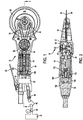
- Figs. 1 and 2 show a handheld dehider 10 according to a first embodiment of the present invention.
- the dehider 10 includes a pair of adjacent cutting disks 32 and 34 having teeth 36 located around the perimeter of each disk.
- the cutting disks 32, 34 are driven by a pair of pushrods 38, 40 in opposed cutting oscillations by an eccentric shaft 42, which is itself driven by pneumatic motor 44 located in the handle 46 of the tool housing.
- the motor 44 drives pinion gear 48, which engages and turns the main drive gear 50.
- the main drive gear 50 is mounted on the eccentric shaft 42 such that rotation of the motor 44 and pinion gear 48 turns the main drive gear 50 and eccentric shaft to drive the pushrods 38, 40 and cutting disks 32, 34.
- the housing includes the handle 46 at the back of the tool and a forward end of the tool that wraps around and below the drive area and extends underneath the cutting disks 32, 34.
- the housing also includes a drive mechanism cover 57 that extends over the drive area and immediately below the cutting disks, and a blade cover 59 located above the cutting disks.
- the housing design allows easy cleaning and removal of the drive mechanism without removing the motor.
- the pushrods 38, 40 are driven by the eccentric shaft 42 such that the back ends of the pushrods 38, 40 are concentrically engaged by the eccentric shaft 42 and move in a circle as the eccentric shaft turns.
- the front ends of the pushrods move forwards and backwards approximately parallel to the axis of the dehider tool, and are connected to the cutting disks 32, 34, with one pushrod to each disk.
- Each pushrod 38, 40 extends to an opposite side of the cutting disk shaft 58 and connects to its associated cutting disk on its respective side of the cutting disk shaft. As each pushrod moves forward, one pushrod turns the cutting disk it is connected to in the opposite direction from the cutting disk being driven by the other pushrod on the opposite side of the cutting disk shaft 58. This produces the opposed cutting disk oscillations of this tool.
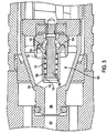
- FIG. 3 An embodiment of the speed governor 100 is shown in Fig. 3 .
- Pressurized air from the air passageway 102 flows into air passageway 104.
- the air passageway 104 includes a valve seat 106.
- Opposite the valve seat 106 is a valve head 108 that can move towards the valve seat 106.
- the valve head 108 has a beveled end 110 that arts to restrict airflow through the space between the valve seat 106 and the beveled end 110. Air that passes through the space between the valve seat 106 and the beveled end 110 eventually powers the motor 44.
- the valve head 108 is biased to the right, as illustrated in Fig. 3 by governor spring 112.
- the governor spring 112 surrounds the core 116 and is trapped between an outwardly projecting lip 114 on the core 116 and an inwardly projecting lip 118 on the valve head 108.
- the valve head 108 also includes an outwardly angled flange 120 that traps a plurality of governor balls 122 between the angled flange 120, the core 116 and a governor housing 124.
- the valve head 108, core 116, governor housing 124, governor balls 122 and the governor spring 112 all spin with the motor 44. As the governor balls 122 spin with the motor, centrifugal force attempts to drive them outward and up the angled flange 120 between the angled flange 120 and the governor housing 124.
- the governor balls 122 act as a movable mass that operates the governor by centrifugal force.
- the outward motion of the governor balls applies a force against the angled flange 120 and the valve head 108, which compresses the spring 112 and moves the beveled end 110 of the valve head 108 towards the valve seat 106.
- the governor 100 will control the speed in the manner described under significant variations in operating load. When the motor is above the desired rotational speed, the governor restricts the flow of pressurized air to decrease speed. When the motor is below the desired rotational speed, the governor opens up to increase airflow and increase the motors speed.
- an air inlet 90 at the rear end of dehider tool handle 46 receives pressurized air used to drive pneumatic motor 44.
- Air inlet 90 is connected via hose 82 to a source of pressurized air, such as an air compressor 70 that may supply pressurized air to multiple air tools, and for other uses, throughout a plant.
- the pressure of the air supplied through hose 82 is set by a line pressure regulator 80, and the air pressure is typically adjusted and set by the dehider tool operator.
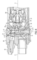
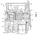
- a regulator 30 is provided built into the tool housing handle 46, as shown by the example of Figs. 6 and 7 , that acts to limit incoming air pressure to the speed governor 100, and thereby maintaining an optimal cutting disk design speed of 6800-7200 strokes/minute.
- the regulator 30 begins to shut off the supply of air, which then forces operators to turn the line pressure regulator down to reduce the air pressure entering the tool, which then brings the tool cutter speed back to the optimal design range. Operation at design speed keeps the cost of operation down, reduces energy (compressed air) usage and cost, and reduces vibration to which operators are exposed.
- the embodiment of the regulator 30 not being a part of the present invention as shown includes both a trigger to activate the dehider air tool and an air pressure regulator, and is fully compatible with the speed governor 100 described herein and in the aforementioned patents.
- the use of the regulator 30 with speed governor 100 produces a dehider tool with more precisely controlled speed and torque operation.
- the regulator 30 will choke the flow of air if line pressure exceeds the safe operation pressure rating for the tool.
- Dehider housing 46 is elongated and speed governor 100 rotates about a longitudinal axis A within the housing.
- regulator 30 is mounted within the rear end of housing 46, between air inlet 90 and speed governor 100, and includes a plunger 15, piston 17, valve 16, valve seat bushing 14, and regulator spring 12.
- Other components may include an O-ring seal 13, shim 18, and retaining ring 11.
- the piston 17 and valve 16 are assembled as one, with the valve stem 24 extending through the valve seat bushing 14 between them, as shown in Figs. 5 , 6 and 7 .
- the plunger 15 and valve 16 move between closed and open positions along an axis B normal to the housing longitudinal axis A ( Fig. 6 ), and comprise mechanisms to switch between air-open and closed positions. Pivoting air control lever 23 contacts the external end of plunger 15 on the dehider housing.
- regulator spring 12 is used to supply a force to the inner end of the piston 17 and is held in place by the plunger 15 and the retaining ring 11.
- a shim 18 may be inserted between the regulator spring 12 and plunger 15.
- a shim 18 may also be placed adjacent the bias spring 21.
- the shim 18 thickness (whether by one or a plurality of shims) is selected to set the exact spring 12, 21 force for the regulation pressure desired.
- the O-ring 13 ensures a leak proof seal is made when the valve face is retracted into the valve seat bushing 14.
- the regulator 30 is housed in the valve body 32, within a guide 19 and bushing 20, which may be made of hardened steel, and biased closed with a bias spring 21 held in place by the access cover 22.
- a bias spring 21 held in place by the access cover 22.
- One or more shims 18 of desired thickness may be used at the ends of spring 21 to set the desired spring force.
- the maximum volume of air allowed is controlled by the positive stop condition for lever 23 and plunger 15 established by the height dimension in direction B of the guide 19.
- Guide 19 determines the maximum degree of movement of the plunger 15 to open the valve 16 and regulates the maximum volume of air flow through the valve 16.
- Air pressure regulation is maintained thru the balancing of the regulator spring and bias spring forces against the force created by the pressure on top of the piston 17, with such air pressure regulation occurring through the speed governor 100 within a predetermined pressure range.
- the piston 17 is forced down due to the force of flowing compressed air passing through valve seat bushing 14 above, plus the force of bias spring 21, it causes the valve 16 to move downward toward valve seat bushing 14 to choke off the air supply, thus reducing the pressure on the piston 17, which is then forced back up by the force of regulator spring 12.
- the regulator may limit the operation pressure of the air tool to a safe level based on the tool design.
- the regulator 30 may prevent tool operation if line pressures exceed a maximum pressure, for example, about 80 to 90 psi. Up to about 75 to 80 psi regulator 30 reduces pressure sufficiently to let the governor control speed. At or above this pressure range regulator 30 shuts off flow of pressurized air completely until the line pressure is reduced.
- the regulator 30 works in conjunction with the governor 100, enhancing an air tool with smooth and precisely controlled speed and torque operation.
- the regulator also provides for fail safe operation with regard to wear items, i.e., the springs and O-rings.
- the present invention provides at least one or more of the following advantages: 1) a speed-governed dehider with an air pressure regulator, and a method of regulating incoming air pressure to a speed governor in a dehider; 2) a dehider air pressure regulator and method of operation that, up to a predetermined limit of line air pressure, reduces pressure sufficiently to let the governor control speed; 3) a dehider air pressure regulator and method of operation that, at or above a predetermined limit of line air pressure, shuts off flow of air completely to the speed governor and pneumatic motor until the line pressure is reduced; and 4) a dehider air pressure regulator and method of operation that works in conjunction with the dehider speed governor, enhancing the tool with smoother and more precisely controlled speed and torque operation.
Landscapes
- Engineering & Computer Science (AREA)
- General Engineering & Computer Science (AREA)
- Life Sciences & Earth Sciences (AREA)
- Physics & Mathematics (AREA)
- Mechanical Engineering (AREA)
- Food Science & Technology (AREA)
- Fluid Mechanics (AREA)
- General Physics & Mathematics (AREA)
- Automation & Control Theory (AREA)
- Forests & Forestry (AREA)
- Fluid-Pressure Circuits (AREA)
- Control Of Fluid Pressure (AREA)
Claims (13)
- Handgehaltener Enthäuter (10), welcher aufweist:ein Gehäuse (10);einen pneumatischen Motor (44) mit einem Lufteinlass (90) in dem Gehäuse (10) zum Bereitstellen eines Druckluftstroms zu dem Motor (44);ein Paar in dem Gehäuse (10) befestigte Schneidscheiben (32, 34), wobei die Schneidscheiben (32, 34) durch den pneumatischen Motor (44) angetrieben werden;einen Drehzahlregler (100) in dem Gehäuse (10) zwischen dem Lufteinlass (90) und dem Motor (44), wobei der Drehzahlregler (100) den Druckluftstrom von dem Lufteinlass (90) zum Motor (44) steuert; undeinen entlang dem Lufteinlass (90) angeordneten Luftdruckregler (30), wobei der Regler (30) ein Ventil (16) zum Öffnen und Schließen des Druckluftstroms in dem Lufteinlass (90), eine Vorspannfeder (21), welche das Ventil (16) in Richtung des Luftstroms durch den Einlass zum Schließen des Ventils (16) beaufschlagt, einen Stempel (15), welcher zum Bewegen des Ventils (16) von einer geschlossenen in eine offene Stellung gegen die Richtung des Luftstroms in dem Lufteinlass (90) bedienbar ist, einen Kolben (17), welcher auf einer Seite mit dem Ventil (16) verbunden und dem Luftstrom durch den Lufteinlass (90) ausgesetzt ist, und eine Stellfeder (12) hat, die zwischen dem Kolben (17) und dem Stempel (15) angeordnet ist,wonach die Stellfeder (12) auf ein Niederdrücken des Stempels (15) den Kolben (17) zum Öffnen des Ventils (16) gegen die Richtung des Luftstroms beaufschlagt, um zu ermöglichen, dass Druckluft durch den Regler (30) und weiter zum Drehzahlregler (100) und zum Motor (44) strömt, undwobei während des Betriebs die Summe der Federkraft der Vorspannfeder (21) und der mittels des Luftstroms durch das Ventil (16) auf den Kolben (17) ausgeübten Kraft durch die Kraft der Stellfeder (12) fortlaufend aufgehoben wird, um den Öffnungsgrad des Ventils (16) aufrecht zu erhalten, und wobei der maximale Druck der Luft durch den Regler (30) und anschließend durch den Drehzahlregler (100) durch Federkräfte allein der Vorspann(21)- und Stellfedern (12) und den Widerstand des Kolbens (17) gegen den Luftstrom durch das Ventil (16) bestimmt wird.
- Enthäuter (10) nach Anspruch 1, wobei ein Ausgleich der Kräfte der Vorspannfeder (21) und der Luftwiderstandskräfte des Kolbens (17) gegenüber der Kraft der Stellfeder (12) eine Luftdruckregelung durch den Drehzahlregler (100) innerhalb eines vorbestimmten Druckbereichs bedingt.
- Enthäuter (10) nach Anspruch 2, ferner umfassend eine oder mehrere Unterlegscheiben (18) angrenzend an eine oder beide der Vorspann(21)- und Stellfedern (12), wobei die Dicke der Unterlegscheibe(n) (18) ein Einstellen der Federkräfte der Vorspann(21)- und Stellfedern (12) ermöglicht.
- Enthäuter (10) nach Anspruch 1, ferner umfassend eine Führung (19) angrenzend an den Stempel (15), wobei die Abmessung der Führung (19) den maximalen Bewegungsgrad des Stempels (15) zum Öffnen des Ventils (16) und zum Regeln des maximalen Luft-Volumenstroms durch das Ventil (16) bestimmt.
- Enthäuter (10) nach Anspruch 1, wobei das Gehäuse (10) gestreckt ist und der Drehzahlregler (100) um eine Längsachse (A) innerhalb des Gehäuses (10) rotiert und wobei der Stempel (15) und das Ventil (16) sich zwischen geschlossenen und offenen Stellungen entlang einer Achse (B) senkrecht zur Gehäuse-Längsachse (A) bewegen.
- Enthäuter (10) nach Anspruch 1, ferner umfassend einen Hebel (23) am Gehäuse (10) zum Niederdrücken des Stempels (15).
- Verfahren zum Regeln eines Luftdrucks zu einem pneumatischen Motor (44) eines handgehaltenen Enthäuters (10), welcher einen Drehzahlregler (100) hat, umfassend:Vorsehen eines Luftdruckreglers (30), welcher entlang eines Lufteinlasses (90) zum Motor (44) angeordnet ist, wobei der Regler (30) ein Ventil (16) zum Öffnen und Schließen des Druckluftstroms in dem Lufteinlass (90), eine Vorspannfeder (21), welche das Ventil (16) in Richtung des Luftstroms durch den Einlass zum Schließen des Ventils (16) beaufschlagt, einen Stempel (15), welcher zum Bewegen des Ventils (16) von einer geschlossenen in eine offene Stellung gegen die Richtung des Luftstroms in dem Lufteinlass (90) bedienbar ist, einen Kolben (17), welcher auf einer Seite mit dem Ventil (16) verbunden und dem Luftstrom durch den Lufteinlass (90) ausgesetzt ist, und eine Stellfeder (12) hat, die zwischen dem Kolben (17) und dem Stempel (15) angeordnet ist; undNiederdrücken des Stempels (15), um die Stellfeder (12) zu veranlassen, den Kolben (17) zum Öffnen des Ventils (16) gegen die Richtung des Luftstroms zu beaufschlagen, um zu ermöglichen, dass Druckluft durch den Regler (30) und weiter zum Drehzahlregler (100) und zum Motor (44) strömt,wobei der maximale Druck der Luft durch den Regler (30) und anschließend durch den Drehzahlregler (100) durch Federkräfte allein der Vorspann(21)- und Stellfedern (12) und den Widerstand des Kolbens (17) gegen den Luftstrom durch das Ventil (16) bestimmt wird.
- Verfahren nach Anspruch 7, wobei sich der pneumatische Motor (44) in einem Gehäuse (10) befindet und sich der Lufteinlass (90) in dem Gehäuse (10) zum Bereitstellen eines Druckluftstroms zu de m Motor (44) befindet, und ein Drehzahlregler (100) in dem Gehäuse (10) zwischen dem Lufteinlass (90) und dem Motor (44) vorgesehen ist, und wobei der Drehzahlregler (100) den Druckluftstrom von dem Lufteinlass (90) zum Motor (44) steuert.
- Verfahren nach Anspruch 8, wobei das Gehäuse (10) gestreckt ist und der Drehzahlregler (100) um eine Längsachse (A) innerhalb des Gehäuses (10) rotiert und wobei der Stempel (15) und das Ventil (16) sich zwischen geschlossenen und offenen Stellungen entlang einer Achse (B) senkrecht zur Gehäuse-Längsachse (A) bewegen.
- Verfahren nach Anspruch 8, wobei das Gehäuse (10) für einen handgehaltenen Enthäuter (10) ist und der pneumatische Motor (44) ein Paar in dem Gehäuse (10) befestigte Schneidscheiben (32, 34) antreibt.
- Verfahren nach Anspruch 10, wobei der Enthäuter (10) mit einer Druckluftquelle (70) bei einem Leitungsdruck, welcher variiert werden kann, verbunden ist und wobei der Luftdruckregler (30) bis zu einem vorbestimmten Leitungsluftdruck arbeitet, um den Druck zum Drehzahlregler (100) ausreichend zu verringern, damit der Regler (100) die Drehzahl steuern kann, und der Luftdruckregler (30) bei dem vorbestimmten Leitungsdruck oder oberhalb des vorbestimmten Leitungsdrucks den Druckluftstrom zum Drehzahlregler (100) vollständig absperrt, bis der Leitungsdruck verringert ist.
- Verfahren nach Anspruch 7, ferner vorsehend eine oder mehrere Unterlegscheiben (18) angrenzend an eine oder beide der Vorspann(21)- und Stellfedern (12) und wobei die Dicke der Unterlegscheibe(n) (18) ein Einstellen der Federkräfte der Vorspann(21)- und Stellfedern (12) ermöglicht.
- Verfahren nach Anspruch 7, ferner vorsehend eine Führung (19) angrenzend an den Stempel (15), wobei die Abmessung der Führung (19) den maximalen Bewegungsgrad des Stempels (15) zum Öffnen des Ventils (16) und zum Regeln des maximalen Luft-Volumenstroms durch das Ventil (16) bestimmt.
Priority Applications (1)
| Application Number | Priority Date | Filing Date | Title |
|---|---|---|---|
| PL17878881T PL3552073T3 (pl) | 2016-12-08 | 2017-12-01 | Zawór regulatora noża do skórowania |
Applications Claiming Priority (3)
| Application Number | Priority Date | Filing Date | Title |
|---|---|---|---|
| US201662431675P | 2016-12-08 | 2016-12-08 | |
| US15/826,906 US10034480B2 (en) | 2016-12-08 | 2017-11-30 | Dehider regulator valve |
| PCT/US2017/064109 WO2018106520A1 (en) | 2016-12-08 | 2017-12-01 | Dehider regulator valve |
Publications (3)
| Publication Number | Publication Date |
|---|---|
| EP3552073A1 EP3552073A1 (de) | 2019-10-16 |
| EP3552073A4 EP3552073A4 (de) | 2020-03-18 |
| EP3552073B1 true EP3552073B1 (de) | 2021-02-10 |
Family
ID=62487608
Family Applications (1)
| Application Number | Title | Priority Date | Filing Date |
|---|---|---|---|
| EP17878881.6A Active EP3552073B1 (de) | 2016-12-08 | 2017-12-01 | Reglerventil für enthäuter |
Country Status (10)
| Country | Link |
|---|---|
| US (1) | US10034480B2 (de) |
| EP (1) | EP3552073B1 (de) |
| AU (1) | AU2017370545B2 (de) |
| BR (1) | BR112019009119B1 (de) |
| CA (1) | CA3038815C (de) |
| ES (1) | ES2858327T3 (de) |
| MX (1) | MX2019004636A (de) |
| PL (1) | PL3552073T3 (de) |
| WO (1) | WO2018106520A1 (de) |
| ZA (1) | ZA201901950B (de) |
Families Citing this family (3)
| Publication number | Priority date | Publication date | Assignee | Title |
|---|---|---|---|---|
| US11375723B2 (en) | 2019-05-22 | 2022-07-05 | Bettcher Industries, Inc. | Power operated scribe saw |
| USD912486S1 (en) | 2019-05-23 | 2021-03-09 | Bettcher Industries Inc. | Dehiding tool |
| US11833701B2 (en) * | 2021-04-30 | 2023-12-05 | Fiskars Finland Oy Ab | Blade receiver assembly and cutting device |
Family Cites Families (8)
| Publication number | Priority date | Publication date | Assignee | Title |
|---|---|---|---|---|
| US4215451A (en) * | 1979-05-10 | 1980-08-05 | Best & Donovan | Dehider |
| US5122092A (en) | 1989-12-13 | 1992-06-16 | Jarvis Products Corporation | Power skinning knife with removable drive mechanism and high efficiency pneumatic motor |
| US5515930A (en) | 1994-06-01 | 1996-05-14 | Glendo Corporation | Handheld pneumatic power tool apparatus |
| US5605287A (en) | 1995-01-17 | 1997-02-25 | Parker-Hannifin Corporation | Airblast fuel nozzle with swirl slot metering valve |
| US20050247750A1 (en) | 2003-07-31 | 2005-11-10 | Burkholder Robert F | Integrated air tool and pressure regulator |
| US7163453B1 (en) * | 2005-09-29 | 2007-01-16 | Jarvis Products Corporation | Dehider with dual counterbalance drive system |
| US7722448B2 (en) | 2006-08-16 | 2010-05-25 | Jarvis Products Corporation | Dehider with governor and strengthened blade |
| US8905827B1 (en) * | 2013-03-14 | 2014-12-09 | Dale R. Ross | Dehider tool and blade therefor |
-
2017
- 2017-11-30 US US15/826,906 patent/US10034480B2/en active Active
- 2017-12-01 AU AU2017370545A patent/AU2017370545B2/en active Active
- 2017-12-01 BR BR112019009119-0A patent/BR112019009119B1/pt active IP Right Grant
- 2017-12-01 CA CA3038815A patent/CA3038815C/en active Active
- 2017-12-01 ES ES17878881T patent/ES2858327T3/es active Active
- 2017-12-01 MX MX2019004636A patent/MX2019004636A/es unknown
- 2017-12-01 WO PCT/US2017/064109 patent/WO2018106520A1/en not_active Ceased
- 2017-12-01 PL PL17878881T patent/PL3552073T3/pl unknown
- 2017-12-01 EP EP17878881.6A patent/EP3552073B1/de active Active
-
2019
- 2019-03-28 ZA ZA2019/01950A patent/ZA201901950B/en unknown
Non-Patent Citations (1)
| Title |
|---|
| None * |
Also Published As
| Publication number | Publication date |
|---|---|
| CA3038815C (en) | 2021-05-04 |
| BR112019009119A2 (pt) | 2019-07-16 |
| ZA201901950B (en) | 2021-01-27 |
| EP3552073A4 (de) | 2020-03-18 |
| US20180160691A1 (en) | 2018-06-14 |
| US10034480B2 (en) | 2018-07-31 |
| PL3552073T3 (pl) | 2021-07-19 |
| CA3038815A1 (en) | 2018-06-14 |
| BR112019009119B1 (pt) | 2021-05-18 |
| ES2858327T3 (es) | 2021-09-30 |
| AU2017370545A1 (en) | 2019-04-11 |
| WO2018106520A1 (en) | 2018-06-14 |
| MX2019004636A (es) | 2019-08-21 |
| AU2017370545B2 (en) | 2020-08-13 |
| EP3552073A1 (de) | 2019-10-16 |
Similar Documents
| Publication | Publication Date | Title |
|---|---|---|
| AU2017370545B2 (en) | Dehider regulator valve | |
| US8047901B2 (en) | Dehider with governor and strengthened blade | |
| EP3051954B1 (de) | Enthäutungswerkzeug | |
| AU2016200975A1 (en) | Air inlet control for air compressor | |
| CN1807019A (zh) | 手持工作器具的供水装置 | |
| KR101174640B1 (ko) | 자동전지가위 | |
| AU2010207759B2 (en) | Handheld Dehider | |
| EP2699386B1 (de) | Einrichtung zur drehzahlregelung eines pneumatisch angetriebenen werkzeugs | |
| US10124465B2 (en) | Pneumatic power tool with an over-speed safety device | |
| WO2007134782A1 (en) | Portable cutting tool |
Legal Events
| Date | Code | Title | Description |
|---|---|---|---|
| STAA | Information on the status of an ep patent application or granted ep patent |
Free format text: STATUS: THE INTERNATIONAL PUBLICATION HAS BEEN MADE |
|
| PUAI | Public reference made under article 153(3) epc to a published international application that has entered the european phase |
Free format text: ORIGINAL CODE: 0009012 |
|
| STAA | Information on the status of an ep patent application or granted ep patent |
Free format text: STATUS: REQUEST FOR EXAMINATION WAS MADE |
|
| 17P | Request for examination filed |
Effective date: 20190418 |
|
| AK | Designated contracting states |
Kind code of ref document: A1 Designated state(s): AL AT BE BG CH CY CZ DE DK EE ES FI FR GB GR HR HU IE IS IT LI LT LU LV MC MK MT NL NO PL PT RO RS SE SI SK SM TR |
|
| AX | Request for extension of the european patent |
Extension state: BA ME |
|
| A4 | Supplementary search report drawn up and despatched |
Effective date: 20200214 |
|
| DAV | Request for validation of the european patent (deleted) | ||
| DAX | Request for extension of the european patent (deleted) | ||
| RIC1 | Information provided on ipc code assigned before grant |
Ipc: A22B 5/16 20060101ALI20200210BHEP Ipc: G05D 16/00 20060101AFI20200210BHEP |
|
| GRAP | Despatch of communication of intention to grant a patent |
Free format text: ORIGINAL CODE: EPIDOSNIGR1 |
|
| STAA | Information on the status of an ep patent application or granted ep patent |
Free format text: STATUS: GRANT OF PATENT IS INTENDED |
|
| INTG | Intention to grant announced |
Effective date: 20200910 |
|
| GRAS | Grant fee paid |
Free format text: ORIGINAL CODE: EPIDOSNIGR3 |
|
| GRAA | (expected) grant |
Free format text: ORIGINAL CODE: 0009210 |
|
| STAA | Information on the status of an ep patent application or granted ep patent |
Free format text: STATUS: THE PATENT HAS BEEN GRANTED |
|
| AK | Designated contracting states |
Kind code of ref document: B1 Designated state(s): AL AT BE BG CH CY CZ DE DK EE ES FI FR GB GR HR HU IE IS IT LI LT LU LV MC MK MT NL NO PL PT RO RS SE SI SK SM TR |
|
| REG | Reference to a national code |
Ref country code: GB Ref legal event code: FG4D |
|
| REG | Reference to a national code |
Ref country code: AT Ref legal event code: REF Ref document number: 1360082 Country of ref document: AT Kind code of ref document: T Effective date: 20210215 Ref country code: CH Ref legal event code: EP |
|
| REG | Reference to a national code |
Ref country code: DE Ref legal event code: R096 Ref document number: 602017032464 Country of ref document: DE |
|
| REG | Reference to a national code |
Ref country code: IE Ref legal event code: FG4D |
|
| REG | Reference to a national code |
Ref country code: NL Ref legal event code: FP |
|
| REG | Reference to a national code |
Ref country code: SE Ref legal event code: TRGR |
|
| REG | Reference to a national code |
Ref country code: CH Ref legal event code: NV Representative=s name: GACHNANG AG PATENTANWAELTE, CH |
|
| REG | Reference to a national code |
Ref country code: LT Ref legal event code: MG9D |
|
| PG25 | Lapsed in a contracting state [announced via postgrant information from national office to epo] |
Ref country code: HR Free format text: LAPSE BECAUSE OF FAILURE TO SUBMIT A TRANSLATION OF THE DESCRIPTION OR TO PAY THE FEE WITHIN THE PRESCRIBED TIME-LIMIT Effective date: 20210210 Ref country code: GR Free format text: LAPSE BECAUSE OF FAILURE TO SUBMIT A TRANSLATION OF THE DESCRIPTION OR TO PAY THE FEE WITHIN THE PRESCRIBED TIME-LIMIT Effective date: 20210511 Ref country code: FI Free format text: LAPSE BECAUSE OF FAILURE TO SUBMIT A TRANSLATION OF THE DESCRIPTION OR TO PAY THE FEE WITHIN THE PRESCRIBED TIME-LIMIT Effective date: 20210210 Ref country code: PT Free format text: LAPSE BECAUSE OF FAILURE TO SUBMIT A TRANSLATION OF THE DESCRIPTION OR TO PAY THE FEE WITHIN THE PRESCRIBED TIME-LIMIT Effective date: 20210611 Ref country code: NO Free format text: LAPSE BECAUSE OF FAILURE TO SUBMIT A TRANSLATION OF THE DESCRIPTION OR TO PAY THE FEE WITHIN THE PRESCRIBED TIME-LIMIT Effective date: 20210510 Ref country code: BG Free format text: LAPSE BECAUSE OF FAILURE TO SUBMIT A TRANSLATION OF THE DESCRIPTION OR TO PAY THE FEE WITHIN THE PRESCRIBED TIME-LIMIT Effective date: 20210510 Ref country code: LT Free format text: LAPSE BECAUSE OF FAILURE TO SUBMIT A TRANSLATION OF THE DESCRIPTION OR TO PAY THE FEE WITHIN THE PRESCRIBED TIME-LIMIT Effective date: 20210210 |
|
| REG | Reference to a national code |
Ref country code: AT Ref legal event code: MK05 Ref document number: 1360082 Country of ref document: AT Kind code of ref document: T Effective date: 20210210 |
|
| PG25 | Lapsed in a contracting state [announced via postgrant information from national office to epo] |
Ref country code: LV Free format text: LAPSE BECAUSE OF FAILURE TO SUBMIT A TRANSLATION OF THE DESCRIPTION OR TO PAY THE FEE WITHIN THE PRESCRIBED TIME-LIMIT Effective date: 20210210 Ref country code: RS Free format text: LAPSE BECAUSE OF FAILURE TO SUBMIT A TRANSLATION OF THE DESCRIPTION OR TO PAY THE FEE WITHIN THE PRESCRIBED TIME-LIMIT Effective date: 20210210 |
|
| PG25 | Lapsed in a contracting state [announced via postgrant information from national office to epo] |
Ref country code: IS Free format text: LAPSE BECAUSE OF FAILURE TO SUBMIT A TRANSLATION OF THE DESCRIPTION OR TO PAY THE FEE WITHIN THE PRESCRIBED TIME-LIMIT Effective date: 20210610 |
|
| REG | Reference to a national code |
Ref country code: ES Ref legal event code: FG2A Ref document number: 2858327 Country of ref document: ES Kind code of ref document: T3 Effective date: 20210930 |
|
| PG25 | Lapsed in a contracting state [announced via postgrant information from national office to epo] |
Ref country code: EE Free format text: LAPSE BECAUSE OF FAILURE TO SUBMIT A TRANSLATION OF THE DESCRIPTION OR TO PAY THE FEE WITHIN THE PRESCRIBED TIME-LIMIT Effective date: 20210210 Ref country code: CZ Free format text: LAPSE BECAUSE OF FAILURE TO SUBMIT A TRANSLATION OF THE DESCRIPTION OR TO PAY THE FEE WITHIN THE PRESCRIBED TIME-LIMIT Effective date: 20210210 Ref country code: SM Free format text: LAPSE BECAUSE OF FAILURE TO SUBMIT A TRANSLATION OF THE DESCRIPTION OR TO PAY THE FEE WITHIN THE PRESCRIBED TIME-LIMIT Effective date: 20210210 Ref country code: AT Free format text: LAPSE BECAUSE OF FAILURE TO SUBMIT A TRANSLATION OF THE DESCRIPTION OR TO PAY THE FEE WITHIN THE PRESCRIBED TIME-LIMIT Effective date: 20210210 |
|
| REG | Reference to a national code |
Ref country code: DE Ref legal event code: R097 Ref document number: 602017032464 Country of ref document: DE |
|
| PG25 | Lapsed in a contracting state [announced via postgrant information from national office to epo] |
Ref country code: RO Free format text: LAPSE BECAUSE OF FAILURE TO SUBMIT A TRANSLATION OF THE DESCRIPTION OR TO PAY THE FEE WITHIN THE PRESCRIBED TIME-LIMIT Effective date: 20210210 Ref country code: DK Free format text: LAPSE BECAUSE OF FAILURE TO SUBMIT A TRANSLATION OF THE DESCRIPTION OR TO PAY THE FEE WITHIN THE PRESCRIBED TIME-LIMIT Effective date: 20210210 Ref country code: SK Free format text: LAPSE BECAUSE OF FAILURE TO SUBMIT A TRANSLATION OF THE DESCRIPTION OR TO PAY THE FEE WITHIN THE PRESCRIBED TIME-LIMIT Effective date: 20210210 |
|
| PLBE | No opposition filed within time limit |
Free format text: ORIGINAL CODE: 0009261 |
|
| STAA | Information on the status of an ep patent application or granted ep patent |
Free format text: STATUS: NO OPPOSITION FILED WITHIN TIME LIMIT |
|
| 26N | No opposition filed |
Effective date: 20211111 |
|
| PG25 | Lapsed in a contracting state [announced via postgrant information from national office to epo] |
Ref country code: AL Free format text: LAPSE BECAUSE OF FAILURE TO SUBMIT A TRANSLATION OF THE DESCRIPTION OR TO PAY THE FEE WITHIN THE PRESCRIBED TIME-LIMIT Effective date: 20210210 |
|
| PG25 | Lapsed in a contracting state [announced via postgrant information from national office to epo] |
Ref country code: SI Free format text: LAPSE BECAUSE OF FAILURE TO SUBMIT A TRANSLATION OF THE DESCRIPTION OR TO PAY THE FEE WITHIN THE PRESCRIBED TIME-LIMIT Effective date: 20210210 |
|
| PG25 | Lapsed in a contracting state [announced via postgrant information from national office to epo] |
Ref country code: IS Free format text: LAPSE BECAUSE OF FAILURE TO SUBMIT A TRANSLATION OF THE DESCRIPTION OR TO PAY THE FEE WITHIN THE PRESCRIBED TIME-LIMIT Effective date: 20210610 |
|
| PG25 | Lapsed in a contracting state [announced via postgrant information from national office to epo] |
Ref country code: MC Free format text: LAPSE BECAUSE OF FAILURE TO SUBMIT A TRANSLATION OF THE DESCRIPTION OR TO PAY THE FEE WITHIN THE PRESCRIBED TIME-LIMIT Effective date: 20210210 |
|
| REG | Reference to a national code |
Ref country code: BE Ref legal event code: MM Effective date: 20211231 |
|
| PG25 | Lapsed in a contracting state [announced via postgrant information from national office to epo] |
Ref country code: LU Free format text: LAPSE BECAUSE OF NON-PAYMENT OF DUE FEES Effective date: 20211201 Ref country code: IE Free format text: LAPSE BECAUSE OF NON-PAYMENT OF DUE FEES Effective date: 20211201 |
|
| PG25 | Lapsed in a contracting state [announced via postgrant information from national office to epo] |
Ref country code: BE Free format text: LAPSE BECAUSE OF NON-PAYMENT OF DUE FEES Effective date: 20211231 |
|
| P01 | Opt-out of the competence of the unified patent court (upc) registered |
Effective date: 20230520 |
|
| PG25 | Lapsed in a contracting state [announced via postgrant information from national office to epo] |
Ref country code: CY Free format text: LAPSE BECAUSE OF FAILURE TO SUBMIT A TRANSLATION OF THE DESCRIPTION OR TO PAY THE FEE WITHIN THE PRESCRIBED TIME-LIMIT Effective date: 20210210 |
|
| PG25 | Lapsed in a contracting state [announced via postgrant information from national office to epo] |
Ref country code: HU Free format text: LAPSE BECAUSE OF FAILURE TO SUBMIT A TRANSLATION OF THE DESCRIPTION OR TO PAY THE FEE WITHIN THE PRESCRIBED TIME-LIMIT; INVALID AB INITIO Effective date: 20171201 |
|
| REG | Reference to a national code |
Ref country code: DE Ref legal event code: R082 Ref document number: 602017032464 Country of ref document: DE Representative=s name: KANDLBINDER, MARKUS, DIPL.-PHYS., DE |
|
| PG25 | Lapsed in a contracting state [announced via postgrant information from national office to epo] |
Ref country code: MK Free format text: LAPSE BECAUSE OF FAILURE TO SUBMIT A TRANSLATION OF THE DESCRIPTION OR TO PAY THE FEE WITHIN THE PRESCRIBED TIME-LIMIT Effective date: 20210210 |
|
| REG | Reference to a national code |
Ref country code: CH Ref legal event code: PK Free format text: BERICHTIGUNGEN |
|
| PG25 | Lapsed in a contracting state [announced via postgrant information from national office to epo] |
Ref country code: MT Free format text: LAPSE BECAUSE OF FAILURE TO SUBMIT A TRANSLATION OF THE DESCRIPTION OR TO PAY THE FEE WITHIN THE PRESCRIBED TIME-LIMIT Effective date: 20210210 |
|
| PG25 | Lapsed in a contracting state [announced via postgrant information from national office to epo] |
Ref country code: TR Free format text: LAPSE BECAUSE OF FAILURE TO SUBMIT A TRANSLATION OF THE DESCRIPTION OR TO PAY THE FEE WITHIN THE PRESCRIBED TIME-LIMIT Effective date: 20210210 |
|
| PGFP | Annual fee paid to national office [announced via postgrant information from national office to epo] |
Ref country code: NL Payment date: 20251112 Year of fee payment: 9 |
|
| REG | Reference to a national code |
Ref country code: CH Ref legal event code: U11 Free format text: ST27 STATUS EVENT CODE: U-0-0-U10-U11 (AS PROVIDED BY THE NATIONAL OFFICE) Effective date: 20260101 |
|
| PGFP | Annual fee paid to national office [announced via postgrant information from national office to epo] |
Ref country code: DE Payment date: 20251104 Year of fee payment: 9 |
|
| PGFP | Annual fee paid to national office [announced via postgrant information from national office to epo] |
Ref country code: GB Payment date: 20251114 Year of fee payment: 9 |
|
| PGFP | Annual fee paid to national office [announced via postgrant information from national office to epo] |
Ref country code: IT Payment date: 20251121 Year of fee payment: 9 |
|
| PGFP | Annual fee paid to national office [announced via postgrant information from national office to epo] |
Ref country code: FR Payment date: 20251110 Year of fee payment: 9 |
|
| PGFP | Annual fee paid to national office [announced via postgrant information from national office to epo] |
Ref country code: SE Payment date: 20251112 Year of fee payment: 9 |
|
| PGFP | Annual fee paid to national office [announced via postgrant information from national office to epo] |
Ref country code: PL Payment date: 20251112 Year of fee payment: 9 |
|
| PGFP | Annual fee paid to national office [announced via postgrant information from national office to epo] |
Ref country code: ES Payment date: 20260119 Year of fee payment: 9 |
|
| PGFP | Annual fee paid to national office [announced via postgrant information from national office to epo] |
Ref country code: CH Payment date: 20260101 Year of fee payment: 9 |