EP3552262B1 - Pile a combustible - Google Patents
Pile a combustible Download PDFInfo
- Publication number
- EP3552262B1 EP3552262B1 EP17805216.3A EP17805216A EP3552262B1 EP 3552262 B1 EP3552262 B1 EP 3552262B1 EP 17805216 A EP17805216 A EP 17805216A EP 3552262 B1 EP3552262 B1 EP 3552262B1
- Authority
- EP
- European Patent Office
- Prior art keywords
- membrane
- fuel cell
- electrode
- region
- edge
- Prior art date
- Legal status (The legal status is an assumption and is not a legal conclusion. Google has not performed a legal analysis and makes no representation as to the accuracy of the status listed.)
- Active
Links
Images

Classifications
-
- H—ELECTRICITY
- H01—ELECTRIC ELEMENTS
- H01M—PROCESSES OR MEANS, e.g. BATTERIES, FOR THE DIRECT CONVERSION OF CHEMICAL ENERGY INTO ELECTRICAL ENERGY
- H01M8/00—Fuel cells; Manufacture thereof
- H01M8/02—Details
- H01M8/0202—Collectors; Separators, e.g. bipolar separators; Interconnectors
- H01M8/0258—Collectors; Separators, e.g. bipolar separators; Interconnectors characterised by the configuration of channels, e.g. by the flow field of the reactant or coolant
-
- H—ELECTRICITY
- H01—ELECTRIC ELEMENTS
- H01M—PROCESSES OR MEANS, e.g. BATTERIES, FOR THE DIRECT CONVERSION OF CHEMICAL ENERGY INTO ELECTRICAL ENERGY
- H01M8/00—Fuel cells; Manufacture thereof
- H01M8/04—Auxiliary arrangements, e.g. for control of pressure or for circulation of fluids
- H01M8/04082—Arrangements for control of reactant parameters, e.g. pressure or concentration
- H01M8/04089—Arrangements for control of reactant parameters, e.g. pressure or concentration of gaseous reactants
- H01M8/04119—Arrangements for control of reactant parameters, e.g. pressure or concentration of gaseous reactants with simultaneous supply or evacuation of electrolyte; Humidifying or dehumidifying
- H01M8/04126—Humidifying
-
- H—ELECTRICITY
- H01—ELECTRIC ELEMENTS
- H01M—PROCESSES OR MEANS, e.g. BATTERIES, FOR THE DIRECT CONVERSION OF CHEMICAL ENERGY INTO ELECTRICAL ENERGY
- H01M8/00—Fuel cells; Manufacture thereof
- H01M8/24—Grouping of fuel cells, e.g. stacking of fuel cells
- H01M8/2465—Details of groupings of fuel cells
- H01M8/2483—Details of groupings of fuel cells characterised by internal manifolds
-
- H—ELECTRICITY
- H01—ELECTRIC ELEMENTS
- H01M—PROCESSES OR MEANS, e.g. BATTERIES, FOR THE DIRECT CONVERSION OF CHEMICAL ENERGY INTO ELECTRICAL ENERGY
- H01M8/00—Fuel cells; Manufacture thereof
- H01M8/10—Fuel cells with solid electrolytes
- H01M2008/1095—Fuel cells with polymeric electrolytes
-
- H—ELECTRICITY
- H01—ELECTRIC ELEMENTS
- H01M—PROCESSES OR MEANS, e.g. BATTERIES, FOR THE DIRECT CONVERSION OF CHEMICAL ENERGY INTO ELECTRICAL ENERGY
- H01M2250/00—Fuel cells for particular applications; Specific features of fuel cell system
- H01M2250/20—Fuel cells in motive systems, e.g. vehicle, ship, plane
-
- Y—GENERAL TAGGING OF NEW TECHNOLOGICAL DEVELOPMENTS; GENERAL TAGGING OF CROSS-SECTIONAL TECHNOLOGIES SPANNING OVER SEVERAL SECTIONS OF THE IPC; TECHNICAL SUBJECTS COVERED BY FORMER USPC CROSS-REFERENCE ART COLLECTIONS [XRACs] AND DIGESTS
- Y02—TECHNOLOGIES OR APPLICATIONS FOR MITIGATION OR ADAPTATION AGAINST CLIMATE CHANGE
- Y02E—REDUCTION OF GREENHOUSE GAS [GHG] EMISSIONS, RELATED TO ENERGY GENERATION, TRANSMISSION OR DISTRIBUTION
- Y02E60/00—Enabling technologies; Technologies with a potential or indirect contribution to GHG emissions mitigation
- Y02E60/30—Hydrogen technology
- Y02E60/50—Fuel cells
-
- Y—GENERAL TAGGING OF NEW TECHNOLOGICAL DEVELOPMENTS; GENERAL TAGGING OF CROSS-SECTIONAL TECHNOLOGIES SPANNING OVER SEVERAL SECTIONS OF THE IPC; TECHNICAL SUBJECTS COVERED BY FORMER USPC CROSS-REFERENCE ART COLLECTIONS [XRACs] AND DIGESTS
- Y02—TECHNOLOGIES OR APPLICATIONS FOR MITIGATION OR ADAPTATION AGAINST CLIMATE CHANGE
- Y02T—CLIMATE CHANGE MITIGATION TECHNOLOGIES RELATED TO TRANSPORTATION
- Y02T90/00—Enabling technologies or technologies with a potential or indirect contribution to GHG emissions mitigation
- Y02T90/40—Application of hydrogen technology to transportation, e.g. using fuel cells
Definitions
- the invention relates to a fuel cell which comprises at least one membrane-electrode unit with a first electrode and a second electrode, which are separated from one another by a membrane, and at least two bipolar plates, which adjoin the membrane-electrode unit on both sides.
- the bipolar plates are broken through by a first supply channel for supplying a fuel and by a second supply channel for supplying an oxidizing agent.
- a fuel cell is a galvanic cell that converts the chemical reaction energy of a continuously supplied fuel and an oxidizing agent into electrical energy.
- a fuel cell is therefore an electrochemical energy converter.
- hydrogen (H2) and oxygen (O2) in particular are converted into water (H2O), electrical energy and heat.
- H2O water
- electrical energy and heat but there are also known fuel cells which work with methanol or methane.
- Proton exchange membrane fuel cells have a centrally arranged membrane that is permeable to protons, i.e. hydrogen ions.
- the oxidizing agent in particular atmospheric oxygen, is thereby spatially separated from the fuel, in particular hydrogen.
- Proton exchange membrane fuel cells also have an anode and a cathode.
- the fuel is fed to the anode of the fuel cell and is catalytically oxidized to protons, releasing electrons.
- the protons pass through the membrane to the cathode.
- the released electrons are derived from the fuel cell and flow to the cathode via an external circuit.
- the oxidizing agent is fed to the fuel cell's cathode and it reacts to water by absorbing electrons from the external circuit and protons that have passed through the membrane to the cathode. The resulting water is drained from the fuel cell.
- the gross response is: O 2 + 4H + + 4e - ⁇ 2H 2 O
- a voltage is applied between the anode and the cathode of the fuel cell.
- several fuel cells can be mechanically arranged one behind the other to form a fuel cell stack and electrically connected in series.
- Distributor plates which are also referred to as bipolar plates, are provided for uniform distribution of the fuel on the anode and for uniform distribution of the oxidizing agent on the cathode.
- the bipolar plates have, for example, channel-like structures for distributing the fuel and the oxidizing agent.
- the bipolar plates can also have structures for conducting a cooling liquid through the fuel cell in order to dissipate heat.
- a fuel cell is known with a membrane electrode unit arranged between two bipolar plates.
- the bipolar plates each have distribution structures for distributing the reaction gases to the electrodes.
- the DE 11 2013 001654 T5 discloses another such fuel cell.
- the membrane of the membrane electrode unit must be kept moist so that the fuel cell works properly. Particularly when the fuel cell is operated at a relatively high temperature, the membrane can dry out due to the increased water absorption capacity of the air, which can impair the function of the fuel cell.
- a fuel cell which comprises at least one membrane electrode unit with a first electrode and a second electrode, which are separated from one another by a membrane, and at least two bipolar plates which are connected to the membrane electrode unit on both sides.
- the bipolar plates are broken through by a first supply channel for supplying a fuel and by a second supply channel for supplying an oxidizing agent.
- the first electrode is also called the anode and the second electrode is also called the cathode.
- the fuel is, for example, hydrogen and the oxidizing agent is, for example, oxygen, in particular oxygen contained in the ambient air.
- the first electrode extends along the membrane in an area which is spaced apart from the first edge of the first supply channel and the second electrode extends along the membrane in an area which is spaced apart from the second edge of the second supply channel.
- the centrally arranged membrane therefore protrudes beyond the electrodes applied on both sides.
- the membrane thus has on both sides areas which are located adjacent to the first supply channel and the second supply channel, which directly adjoin the first distribution structure or the second distribution structure and are free of the electrodes.
- Fuel that is conducted to the first electrode via the first supply channel and the first distribution structure thus also flows over regions of the membrane and can thus transport moisture in the form of water vapor directly to the membrane.
- Oxidizing agent via the second supply channel and the second distribution structure is passed to the second electrode, thus also flows over areas of the membrane and can thus transport moisture in the form of water vapor directly to the membrane.
- the membrane is preferably also permeable to water vapor. Moisture in the form of water vapor can thus be transported from the first distribution structure through the membrane to the second distribution structure and also from the second distribution structure through the membrane to the first distribution structure.
- the bipolar plates are pierced by a first discharge channel for discharging the fuel, the first distribution structure being connected to a first edge of the first discharge channel.
- the first discharge channel serves to discharge unused fuel from the first distribution structure.
- the first electrode extends along the membrane in an area which is also spaced apart from the first edge of the first discharge channel.
- the membrane thus also has an area which is located adjacent to the first discharge channel, which directly adjoins the first distribution structure and is free of the first electrode.
- the first distribution structure preferably has a first inflow area adjoining the first edge of the first supply channel and a first outflow area adjoining the first edge of the first discharge channel.
- a first main distribution area which has a rectangular cross section, is arranged between the first inflow area and the first outflow area.
- the first electrode preferably extends along the membrane in an area which is spaced apart from the first inflow area and from the first outflow area. The first electrode therefore only adjoins the first main distribution area of the first distribution structure.
- the bipolar plates are pierced by a second discharge channel for discharging the oxidizing agent, wherein the second distribution structure adjoins a second edge of the second discharge channel.
- the second discharge channel serves to discharge unused oxidizing agent from the second distribution structure.
- the second electrode extends along the membrane in an area which is also spaced apart from the second edge of the second discharge channel.
- the membrane thus also has an area which is located adjacent to the second discharge channel, which directly adjoins the second distribution structure and is free of the second electrode.
- the second distribution structure preferably has a second inflow area adjoining the second edge of the second supply channel and a second outflow area adjoining the second edge of the second discharge channel.
- a second main distribution area which has a rectangular cross section, is arranged between the second inflow area and the second outflow area.
- the second electrode preferably extends along the membrane in an area which is spaced apart from the second inflow area and from the second outflow area. The second electrode thus only adjoins the second main distribution area of the second distribution structure.
- the electrodes are preferably arranged congruently on the membrane.
- the first electrode and the second electrode therefore have a similar cross section and are attached to opposite regions of the membrane.
- the membrane electrode unit is thus designed to be mirror-symmetrical.
- a fuel cell according to the invention is advantageously used in an electric vehicle (EV).
- EV electric vehicle
- the configuration of the fuel cell according to the invention creates areas on the membrane which directly adjoin the distribution structures and which are free of electrodes. This allows the membrane of the membrane electrode unit always be sufficiently moistened. Even when the fuel cell is operated at a relatively high temperature, the membrane can be prevented from drying out.
- An external humidifier for humidifying the membrane can be designed to be smaller, or the membrane does not need to be humidified by an external humidifier, which saves space and costs.
- Air flowing into the second distribution structure is heated before it reaches the cathode.
- water is transferred from the first distribution structure through the membrane into the second distribution structure through a vapor pressure gradient before the cathode.
- This process takes place in the first distribution structure behind the anode.
- the air enriched with reaction water behind the cathode has an additional path and time to transfer water through the membrane into the first distribution structure.
- the inflowing hydrogen is heated before the anode and has an additional path and time to absorb water from the second distribution structure.
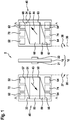
- Fig. 1 an exploded view of a fuel cell 2 according to the invention is shown.
- the fuel cell 2 has a membrane electrode unit 10, which comprises a first electrode 21, a second electrode 22 and a membrane 18.
- the two electrodes 21, 22 are arranged on opposite sides of the membrane 18 and are thus separated from one another by the membrane 18.
- the first electrode 21 is also referred to below as the anode 21 and the second electrode 22 is also referred to as the cathode 22 below.
- the electrodes 21, 22 are arranged congruently on the membrane 18.
- the anode 21 and the cathode 22 have a similar cross section and are attached to opposite regions of the membrane 18.
- the membrane electrode unit 10 is thus designed to be mirror-symmetrical.
- the centrally arranged membrane 18 protrudes beyond the electrodes 21, 22 applied on both sides.
- the membrane 18 is designed as a polymer electrolyte membrane.
- the membrane 18 is permeable to hydrogen ions, that is to say H + ions.
- the membrane 18 is also permeable to water vapor.
- water of reaction that arises at the cathode 22 during the reaction taking place in the fuel cell 2 can thus diffuse into the membrane 18 and through the membrane 18 to the anode 21.
- the fuel cell 2 also has two bipolar plates 40, which are connected to the membrane electrode unit 10 on both sides.
- the bipolar plates 40 are each shown here in a plan view.
- a first surface 33 of a bipolar plate 40 is shown here, which in the assembled state of the Fuel cell 2 facing the anode 21.
- a second surface 34 of the other bipolar plate 40 is shown, which surface faces the cathode 22 in the assembled state of the fuel cell 2.
- the one bipolar plate 40 When assembling the fuel cell 2, the one bipolar plate 40, the first surface 33 of which is shown, must therefore be rotated by 90 ° about a first axis 35 in a first direction of rotation 37.
- the other bipolar plate 40, the second surface 34 of which is shown, must be rotated through 90 ° in a second direction of rotation 38 about a second axis 36 when the fuel cell 2 is being assembled.
- the two bipolar plates 40 are pierced by a first supply channel 52 for supplying a fuel and by a second supply channel 64 for supplying an oxidizing agent. Furthermore, the two bipolar plates 40 are broken through by a first discharge channel 54 for discharging unused fuel and by a second discharge channel 62 for discharging unused oxidizing agent and water. The two bipolar plates 40 are also pierced by a third supply channel 74 for supplying a coolant and by a third discharge channel 72 for discharging the coolant. The coolant is used to cool the fuel cell 2 during operation.
- the first supply channel 52, the second discharge channel 62 and the third discharge channel 72 are introduced on a head side of the bipolar plates 40.
- the second supply channel 64, the first discharge channel 54 and the third supply channel 74 are introduced on an opposite foot side.
- the fuel thus flows from the head side to the foot side and the oxidizing agent and the coolant flow in the opposite direction from the foot side to the head side.
- the bipolar plates 40 each comprise a first distribution structure 50 for distributing the fuel, which is arranged on the first surface 33 and faces the anode 21.
- the first distribution structure 50 extends from a first edge 57 of the first supply channel 52 to a first edge 58 of the first discharge channel 54.
- the fuel flows from the fuel cell 2 during operation the first supply channel 52 to the first discharge channel 54 in a first flow direction 43.
- the first distribution structure 50 has a first inflow area 51, which adjoins the first edge 57 of the first feed channel 52, and a first outflow area 59, which adjoins the first edge 58 of the first discharge channel 54.
- a first main distribution area 53 which has a rectangular cross section, is arranged between the first inflow area 51 and the first outflow area 59.
- the bipolar plates 40 each include a second distribution structure 60 for distributing the oxidizing agent, which is arranged on the second surface 34 and faces the cathode 22.
- the second distribution structure 60 extends from a second edge 67 of the second supply channel 64 to a second edge 68 of the second discharge channel 62.
- the oxidizing agent flows from the second supply channel 64 to the second discharge channel 62 in a second flow direction 44.
- the second distribution structure 60 has a second inflow area 69, which adjoins the second edge 67 of the second feed channel 64, and a second outflow area 61, which adjoins the second edge 68 of the second discharge channel 62.
- a second main distribution area 63 which has a rectangular cross section, is arranged between the second inflow area 69 and the second outflow area 61.
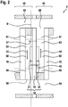
- FIG. 14 is a section through the assembled fuel cell 2 along the section lines A - A from FIG Figure 1 shown.
- the fuel cell 2 is part of a fuel cell stack which is composed of alternately arranged bipolar plates 40 and membrane electrode units 10.
- the bipolar plates 40 and the membrane electrode unit 10 are arranged in such a way that the anode 21 of the first distribution structure 50 faces the one bipolar plate 40 and that the cathode 22 of the second distribution structure 60 faces the other bipolar plate 40.
- the bipolar plates 40 comprise a third distribution structure 70, which extends from the third supply channel 74, not visible here, to the third discharge channel 72, also not visible here.
- the third distribution structure 70 is in each case arranged between the first distribution structure 50 and the second distribution structure 60 and serves to convey the coolant through the bipolar plate 40 and through the fuel cell 2.
- the anode 21 extends along the membrane 18 in a region which is spaced apart from the first edge 57 of the first feed channel 52, which is not visible here, and from the first edge 58 of the first discharge channel 54.
- the anode 21 extends along the membrane 18 in a region which is spaced apart from the first inflow region 51 and from the first outflow region 59.
- the anode 21 thus only adjoins the first main distribution area 53 of the first distribution structure 50 and protrudes into it.
- the membrane 18 thus has on the side of the anode 21 a region which is located adjacent to the first supply channel 52 and is free of the anode 21.
- the membrane 18 thus also has an area which is located adjacent to the first discharge channel 54 and is free of the anode 21. These two areas, which are free of the anode 21, directly adjoin the first distribution structure 50.
- the cathode 22 extends along the membrane 18 in a region which is spaced apart from the second edge 67 of the second supply channel 64, which is not visible here, and from the second edge 68 of the second discharge channel 62.
- the cathode 22 extends along the membrane 18 in a region which is spaced apart from the second inflow region 69 and from the second outflow region 61.
- the cathode 22 thus only adjoins the second main distribution area 63 of the second distribution structure 60 and protrudes into it.
- the membrane 18 thus has an area on the cathode 22 side which is located adjacent to the second supply channel 64 and is free of the cathode 22.
- the membrane 18 thus also has a region which is located adjacent to the second discharge channel 62 and is free of the cathode 22. These two areas, which are free of the cathode 22, directly adjoin the second distribution structure 60.
- fuel is conducted via the first supply channel 52 and the first distribution structure 50 to the anode 21 and further to the first discharge channel 54.
- the fuel also flows in the first flow direction 43 over the areas of the membrane 18 which are free of the anode 21.
- oxidizing agent is conducted via the second supply channel 64 and the second distribution structure 60 to the cathode 22 and further to the second discharge channel 62.
- the oxidizing agent thereby also flows in the second flow direction 44 over the regions of the membrane 18 which are free of the cathode 22.
- the fuel in this case hydrogen, is catalytically oxidized at the anode 21 with the release of electrons into protons.
- the protons pass through the membrane 18 to the cathode 22.
- the electrons released are diverted from the fuel cell 2 and flow to the cathode 22 via an external circuit. which have passed through the membrane 18 to the cathode 22, to water.
- the water that is produced at the cathode 22 during the reaction taking place in the fuel cell 2 can partially flow from the second distribution structure 60 in a first diffusion direction 47 into the membrane 18 and through the membrane 18 into the first distribution structure 50 and to the anode 21 diffuse.
- the water diffused in the first diffusion direction 47 is absorbed by the fuel flowing in the first distribution structure 50.
- the water absorbed by the fuel can then diffuse from the first distribution structure 50 in a second diffusion direction 48 into the membrane 18 and through the membrane 18 into the second distribution structure 60 and to the cathode 22. That diffused in the second diffusion direction 48 Water is taken up by the oxidizing agent flowing in the second distribution structure 60.
- the regions of the membrane 18 which are free of electrodes 21, 22 and adjoin the distribution structures 50, 60 thus enable constant diffusion of water into the membrane 18 and through the membrane 18.
- the membrane 18 is constantly moistened. Excess water is diverted from the fuel cell 2, in particular from the second distribution structure 60 via the second discharge channel 62.
- FIG. 11 shows a section through the assembled fuel cell 2 along the section line BB from FIG Figure 2 .
- the membrane 18 has a centrally located area on which the anode 21 is arranged.
- the membrane 18 also has a region which extends over part of the first main distribution region 53 and over the first inflow region 51 and which is free of the anode 21.
- the membrane 18 also has a region which extends over part of the first main distribution region 53 and over the first outflow region 59 and which is free from the anode 21.
Landscapes
- Life Sciences & Earth Sciences (AREA)
- Engineering & Computer Science (AREA)
- Manufacturing & Machinery (AREA)
- Sustainable Development (AREA)
- Sustainable Energy (AREA)
- Chemical & Material Sciences (AREA)
- Chemical Kinetics & Catalysis (AREA)
- Electrochemistry (AREA)
- General Chemical & Material Sciences (AREA)
- Fuel Cell (AREA)
- Electric Propulsion And Braking For Vehicles (AREA)
Claims (10)
- Pile à combustible (2), comprenant
au moins une unité d'électrode à membrane (10) pourvue d'une première électrode (21) et d'une deuxième électrode (22) qui sont séparées l'une de l'autre par une membrane (18), et
au moins deux plaques bipolaires (40) qui se raccordent des deux côtés à l'unité d'électrode à membrane (10),
les plaques bipolaires (40) étant transpercées par un premier canal d'alimentation (52) servant à l'alimentation en combustible et par un deuxième canal d'alimentation (64) servant à l'alimentation en agent oxydant,
une première structure de répartition (50) qui fait face à la première électrode (21) se raccordant à une première arête (57) du premier canal d'alimentation (52) et une deuxième structure de répartition (60) qui fait face à la deuxième électrode (22) se raccordant à une deuxième arête (67) du deuxième canal d'alimentation (64),
la première électrode (21) s'étendant le long de la membrane (18) dans une zone qui est espacée de la première arête (57) du premier canal d'alimentation (52) et
la deuxième électrode (22) s'étendant le long de la membrane (18) dans une zone qui est espacée de la deuxième arête (67) du deuxième canal d'alimentation (64),
caractérisée en ce que
la membrane (18) possède des deux côtés des zones qui sont placées adjacentes au premier canal d'alimentation (52) et au deuxième canal d'alimentation (64), qui sont directement contiguëes de la première structure de répartition (50) ou de la deuxième structure de répartition (60) et qui sont dépourvues des électrodes (21, 22). - Pile à combustible (2) selon la revendication 1, caractérisée en ce que la membrane (18) est perméable à la vapeur d'eau.
- Pile à combustible (2) selon l'une des revendications précédentes, caractérisée en ce que
les plaques bipolaires (40) sont transpercées par un premier canal d'évacuation (54) servant à l'évacuation du combustible,
la première structure de répartition (50) se raccordant à une première arête (58) du premier canal d'évacuation (54) et
la première électrode (21) s'étendant le long de la membrane (18) dans une zone qui
est espacée de la première arête (58) du premier canal d'évacuation (54). - Pile à combustible (2) selon la revendication 3, caractérisée en ce que la première structure de répartition (50)
possède une première zone de flux entrant (51) qui se raccorde à la première arête (57) du premier canal d'alimentation (52) et une première zone de flux sortant (59) qui se raccorde à la première arête (58) du premier canal d'évacuation (54),
une première zone de répartition principale (53) étant disposée entre la première zone de flux entrant (51) et la première zone de flux sortant (59), laquelle possède une section transversale rectangulaire. - Pile à combustible (2) selon la revendication 4, caractérisée en ce que la première électrode (21) s'étend le long de la membrane (18) dans une zone qui
est espacée de la première zone de flux entrant (51) et de la première zone de flux sortant (59). - Pile à combustible (2) selon l'une des revendications précédentes, caractérisée en ce que
les plaques bipolaires (40) sont transpercées par un deuxième canal d'évacuation (62) servant à l'évacuation de l'agent oxydant,
la deuxième structure de répartition (60) se raccordant à une deuxième arête (68) du deuxième canal d'évacuation (62) et
la deuxième électrode (22) s'étendant le long de la membrane (18) dans une zone qui
est espacée de la deuxième arête (68) du deuxième canal d'évacuation (62). - Pile à combustible (2) selon la revendication 6, caractérisée en ce que la deuxième structure de répartition (60)
possède une deuxième zone de flux entrant (69) qui se raccorde à la deuxième arête (67) du deuxième canal d'alimentation (64) et une deuxième zone de flux sortant (61) qui se raccorde à la deuxième arête (68) du deuxième canal d'évacuation (62),
une deuxième zone de répartition principale (63) étant disposée entre la deuxième zone de flux entrant (69) et la deuxième zone de flux sortant (61), laquelle possède une section transversale rectangulaire. - Pile à combustible (2) selon la revendication 7, caractérisée en ce que la deuxième électrode (22) s'étend le long de la membrane (18) dans une zone qui
est espacée de la deuxième zone de flux entrant (69) et de la deuxième zone de flux sortant (61). - Pile à combustible (2) selon l'une des revendications précédentes, caractérisée en ce que les électrodes (21, 22) sont disposées de manière coïncidente sur la membrane (18).
- Utilisation d'une pile à combustible (2) selon l'une de revendications précédentes dans un véhicule électrique (EV) .
Applications Claiming Priority (2)
| Application Number | Priority Date | Filing Date | Title |
|---|---|---|---|
| DE102016224676.3A DE102016224676A1 (de) | 2016-12-12 | 2016-12-12 | Brennstoffzelle |
| PCT/EP2017/080965 WO2018108547A1 (fr) | 2016-12-12 | 2017-11-30 | Pile à combustible |
Publications (2)
| Publication Number | Publication Date |
|---|---|
| EP3552262A1 EP3552262A1 (fr) | 2019-10-16 |
| EP3552262B1 true EP3552262B1 (fr) | 2021-01-06 |
Family
ID=60484394
Family Applications (1)
| Application Number | Title | Priority Date | Filing Date |
|---|---|---|---|
| EP17805216.3A Active EP3552262B1 (fr) | 2016-12-12 | 2017-11-30 | Pile a combustible |
Country Status (7)
| Country | Link |
|---|---|
| US (1) | US11081707B2 (fr) |
| EP (1) | EP3552262B1 (fr) |
| JP (1) | JP7171571B2 (fr) |
| KR (1) | KR102469253B1 (fr) |
| CN (1) | CN110268565B (fr) |
| DE (1) | DE102016224676A1 (fr) |
| WO (1) | WO2018108547A1 (fr) |
Families Citing this family (1)
| Publication number | Priority date | Publication date | Assignee | Title |
|---|---|---|---|---|
| CN117334946B (zh) * | 2023-12-01 | 2024-03-29 | 北京氢璞创能科技有限公司 | 一种流场优化的质子交换膜燃料电池单电池 |
Family Cites Families (7)
| Publication number | Priority date | Publication date | Assignee | Title |
|---|---|---|---|---|
| JP2000323159A (ja) | 1999-05-11 | 2000-11-24 | Fuji Electric Co Ltd | 固体高分子型燃料電池 |
| JP4981400B2 (ja) | 2006-05-01 | 2012-07-18 | 本田技研工業株式会社 | 燃料電池 |
| DE112007001059B4 (de) | 2006-05-01 | 2015-05-13 | Honda Motor Co., Ltd. | Brennstoffzelle |
| JP5217284B2 (ja) | 2007-08-01 | 2013-06-19 | 日産自動車株式会社 | 燃料電池 |
| DE112013001654B4 (de) | 2012-03-23 | 2016-03-24 | Honda Motor Co., Ltd. | Brennstoffzelle |
| DE102013226815A1 (de) | 2013-12-20 | 2015-06-25 | Robert Bosch Gmbh | Brennstoffzelle |
| FR3026232B1 (fr) | 2014-09-19 | 2021-04-02 | Commissariat Energie Atomique | Plaque de guidage d’ecoulement d’un fluide pour reacteur electrochimique et ensemble comportant cette plaque |
-
2016
- 2016-12-12 DE DE102016224676.3A patent/DE102016224676A1/de not_active Withdrawn
-
2017
- 2017-11-30 JP JP2019530748A patent/JP7171571B2/ja active Active
- 2017-11-30 KR KR1020197019983A patent/KR102469253B1/ko active Active
- 2017-11-30 CN CN201780086235.9A patent/CN110268565B/zh active Active
- 2017-11-30 EP EP17805216.3A patent/EP3552262B1/fr active Active
- 2017-11-30 US US16/468,382 patent/US11081707B2/en active Active
- 2017-11-30 WO PCT/EP2017/080965 patent/WO2018108547A1/fr not_active Ceased
Non-Patent Citations (1)
| Title |
|---|
| None * |
Also Published As
| Publication number | Publication date |
|---|---|
| CN110268565A (zh) | 2019-09-20 |
| US11081707B2 (en) | 2021-08-03 |
| KR102469253B1 (ko) | 2022-11-21 |
| JP7171571B2 (ja) | 2022-11-15 |
| WO2018108547A1 (fr) | 2018-06-21 |
| US20190334181A1 (en) | 2019-10-31 |
| KR20190090007A (ko) | 2019-07-31 |
| CN110268565B (zh) | 2022-08-12 |
| DE102016224676A1 (de) | 2018-06-14 |
| EP3552262A1 (fr) | 2019-10-16 |
| JP2020513665A (ja) | 2020-05-14 |
Similar Documents
| Publication | Publication Date | Title |
|---|---|---|
| EP3884535B1 (fr) | Plaque de pile à combustible, plaque bipolaire et système de pile à combustible | |
| DE102020215014A1 (de) | Bipolarplatte für eine elektrochemische Zelle und elektrochemische Zelle | |
| DE102019218380A1 (de) | Brennstoffzellenanordnung und Verfahren zur Herstellung einer Brennstoffzellenanordnung | |
| DE10220183A1 (de) | Brennstoffzelle | |
| DE102020213574A1 (de) | Verteilerplatte für eine elektrochemische Zelle, elektrochemische Zelle und Verfahren zum Betrieb einer elektrochemischen Zelle | |
| WO2022111922A1 (fr) | Plaque bipolaire pour cellule électrochimique, agencement de cellules électrochimiques et procédé de fonctionnement dudit agencement de cellules électrochimiques | |
| EP3552262B1 (fr) | Pile a combustible | |
| DE102022200797A1 (de) | Membran-Elektroden-Einheit, Anordnung elektrochemischer Zellen und Verfahren zur Herstellung einer Membran-Elektroden-Einheit | |
| DE10233982B4 (de) | Bipolare Platte für eine Brennstoffzelle und Brennstoffzellenstapel | |
| EP4150687B1 (fr) | Plaque bipolaire et empilement de piles à combustible | |
| WO2003090301A2 (fr) | Plaque d'electrodes comportant une zone d'humidification | |
| EP1833112B1 (fr) | Unité de membrane d'électrodes et cellule combustible | |
| DE102019205069A1 (de) | Bipolarplatte für Brennstoffzellen, Brennstoffzellenstapel mit solchen Bipolarplatten sowie Fahrzeug mit einem solchen Brennstoffzellenstapel | |
| DE102014219164A1 (de) | Brennstoffzellenstapel mit integriertem Befeuchter sowie Fahrzeug mit einem solchen | |
| DE102009043208A1 (de) | Materialauslegung, um eine Leistungsfähigkeit einer Brennstoffzelle bei hoher Mittentemperatur mit ultradünnen Elektroden zu ermöglichen | |
| EP4165703A1 (fr) | Plaque bipolaire à obturateur insérable et empilement de cellules élémentaires | |
| WO2022090125A1 (fr) | Plaque bipolaire et empilement de piles à combustible | |
| DE102020215022A1 (de) | Bipolarplatte für eine elektrochemische Zelle, Anordnung elektrochemischer Zellen und Verfahren zum Betrieb einer Anordnung elektrochemischer Zellen | |
| DE102020203683A1 (de) | Vorrichtung zur Mediendurchführung und Verfahren zur Herstellung | |
| WO2020152084A1 (fr) | Plaque bipolaire pour pile à combustible et pile à combustible | |
| DE102019206117A1 (de) | Brennstoffzellenstapel umfassend variable Biopolarplatten | |
| DE102022205235A1 (de) | Verfahren zum Betreiben mindestens einer elektrochemischen Zelle | |
| DE102018201056A1 (de) | Brennstoffzelle und Brennstoffzellenstapel | |
| DE102020128436A1 (de) | Gewebestruktur mit integrierter Be- und Entfeuchtungsfunktion für eine Bipolarplatte und für einen Brennstoffzellenstapel | |
| DE102024106293A1 (de) | Bipolarplatte für Brennstoffzellen |
Legal Events
| Date | Code | Title | Description |
|---|---|---|---|
| STAA | Information on the status of an ep patent application or granted ep patent |
Free format text: STATUS: UNKNOWN |
|
| STAA | Information on the status of an ep patent application or granted ep patent |
Free format text: STATUS: THE INTERNATIONAL PUBLICATION HAS BEEN MADE |
|
| PUAI | Public reference made under article 153(3) epc to a published international application that has entered the european phase |
Free format text: ORIGINAL CODE: 0009012 |
|
| STAA | Information on the status of an ep patent application or granted ep patent |
Free format text: STATUS: REQUEST FOR EXAMINATION WAS MADE |
|
| 17P | Request for examination filed |
Effective date: 20190712 |
|
| AK | Designated contracting states |
Kind code of ref document: A1 Designated state(s): AL AT BE BG CH CY CZ DE DK EE ES FI FR GB GR HR HU IE IS IT LI LT LU LV MC MK MT NL NO PL PT RO RS SE SI SK SM TR |
|
| AX | Request for extension of the european patent |
Extension state: BA ME |
|
| DAV | Request for validation of the european patent (deleted) | ||
| DAX | Request for extension of the european patent (deleted) | ||
| RAP1 | Party data changed (applicant data changed or rights of an application transferred) |
Owner name: ROBERT BOSCH GMBH |
|
| REG | Reference to a national code |
Ref country code: DE Ref legal event code: R079 Ref document number: 502017009007 Country of ref document: DE Free format text: PREVIOUS MAIN CLASS: H01M0008025800 Ipc: H01M0008041190 |
|
| GRAP | Despatch of communication of intention to grant a patent |
Free format text: ORIGINAL CODE: EPIDOSNIGR1 |
|
| STAA | Information on the status of an ep patent application or granted ep patent |
Free format text: STATUS: GRANT OF PATENT IS INTENDED |
|
| RIC1 | Information provided on ipc code assigned before grant |
Ipc: H01M 8/0258 20160101ALI20200528BHEP Ipc: H01M 8/04119 20160101AFI20200528BHEP Ipc: H01M 8/1018 20160101ALN20200528BHEP Ipc: H01M 8/2483 20160101ALI20200528BHEP |
|
| INTG | Intention to grant announced |
Effective date: 20200619 |
|
| GRAS | Grant fee paid |
Free format text: ORIGINAL CODE: EPIDOSNIGR3 |
|
| GRAA | (expected) grant |
Free format text: ORIGINAL CODE: 0009210 |
|
| STAA | Information on the status of an ep patent application or granted ep patent |
Free format text: STATUS: THE PATENT HAS BEEN GRANTED |
|
| AK | Designated contracting states |
Kind code of ref document: B1 Designated state(s): AL AT BE BG CH CY CZ DE DK EE ES FI FR GB GR HR HU IE IS IT LI LT LU LV MC MK MT NL NO PL PT RO RS SE SI SK SM TR |
|
| REG | Reference to a national code |
Ref country code: GB Ref legal event code: FG4D Free format text: NOT ENGLISH |
|
| REG | Reference to a national code |
Ref country code: AT Ref legal event code: REF Ref document number: 1353345 Country of ref document: AT Kind code of ref document: T Effective date: 20210115 Ref country code: CH Ref legal event code: EP |
|
| REG | Reference to a national code |
Ref country code: DE Ref legal event code: R096 Ref document number: 502017009007 Country of ref document: DE |
|
| REG | Reference to a national code |
Ref country code: IE Ref legal event code: FG4D Free format text: LANGUAGE OF EP DOCUMENT: GERMAN |
|
| REG | Reference to a national code |
Ref country code: NL Ref legal event code: MP Effective date: 20210106 |
|
| REG | Reference to a national code |
Ref country code: LT Ref legal event code: MG9D |
|
| PG25 | Lapsed in a contracting state [announced via postgrant information from national office to epo] |
Ref country code: NO Free format text: LAPSE BECAUSE OF FAILURE TO SUBMIT A TRANSLATION OF THE DESCRIPTION OR TO PAY THE FEE WITHIN THE PRESCRIBED TIME-LIMIT Effective date: 20210406 Ref country code: PT Free format text: LAPSE BECAUSE OF FAILURE TO SUBMIT A TRANSLATION OF THE DESCRIPTION OR TO PAY THE FEE WITHIN THE PRESCRIBED TIME-LIMIT Effective date: 20210506 Ref country code: FI Free format text: LAPSE BECAUSE OF FAILURE TO SUBMIT A TRANSLATION OF THE DESCRIPTION OR TO PAY THE FEE WITHIN THE PRESCRIBED TIME-LIMIT Effective date: 20210106 Ref country code: HR Free format text: LAPSE BECAUSE OF FAILURE TO SUBMIT A TRANSLATION OF THE DESCRIPTION OR TO PAY THE FEE WITHIN THE PRESCRIBED TIME-LIMIT Effective date: 20210106 Ref country code: GR Free format text: LAPSE BECAUSE OF FAILURE TO SUBMIT A TRANSLATION OF THE DESCRIPTION OR TO PAY THE FEE WITHIN THE PRESCRIBED TIME-LIMIT Effective date: 20210407 Ref country code: BG Free format text: LAPSE BECAUSE OF FAILURE TO SUBMIT A TRANSLATION OF THE DESCRIPTION OR TO PAY THE FEE WITHIN THE PRESCRIBED TIME-LIMIT Effective date: 20210406 Ref country code: LT Free format text: LAPSE BECAUSE OF FAILURE TO SUBMIT A TRANSLATION OF THE DESCRIPTION OR TO PAY THE FEE WITHIN THE PRESCRIBED TIME-LIMIT Effective date: 20210106 |
|
| PG25 | Lapsed in a contracting state [announced via postgrant information from national office to epo] |
Ref country code: SE Free format text: LAPSE BECAUSE OF FAILURE TO SUBMIT A TRANSLATION OF THE DESCRIPTION OR TO PAY THE FEE WITHIN THE PRESCRIBED TIME-LIMIT Effective date: 20210106 Ref country code: RS Free format text: LAPSE BECAUSE OF FAILURE TO SUBMIT A TRANSLATION OF THE DESCRIPTION OR TO PAY THE FEE WITHIN THE PRESCRIBED TIME-LIMIT Effective date: 20210106 Ref country code: PL Free format text: LAPSE BECAUSE OF FAILURE TO SUBMIT A TRANSLATION OF THE DESCRIPTION OR TO PAY THE FEE WITHIN THE PRESCRIBED TIME-LIMIT Effective date: 20210106 Ref country code: LV Free format text: LAPSE BECAUSE OF FAILURE TO SUBMIT A TRANSLATION OF THE DESCRIPTION OR TO PAY THE FEE WITHIN THE PRESCRIBED TIME-LIMIT Effective date: 20210106 |
|
| PG25 | Lapsed in a contracting state [announced via postgrant information from national office to epo] |
Ref country code: IS Free format text: LAPSE BECAUSE OF FAILURE TO SUBMIT A TRANSLATION OF THE DESCRIPTION OR TO PAY THE FEE WITHIN THE PRESCRIBED TIME-LIMIT Effective date: 20210506 |
|
| REG | Reference to a national code |
Ref country code: DE Ref legal event code: R097 Ref document number: 502017009007 Country of ref document: DE |
|
| PG25 | Lapsed in a contracting state [announced via postgrant information from national office to epo] |
Ref country code: SM Free format text: LAPSE BECAUSE OF FAILURE TO SUBMIT A TRANSLATION OF THE DESCRIPTION OR TO PAY THE FEE WITHIN THE PRESCRIBED TIME-LIMIT Effective date: 20210106 Ref country code: CZ Free format text: LAPSE BECAUSE OF FAILURE TO SUBMIT A TRANSLATION OF THE DESCRIPTION OR TO PAY THE FEE WITHIN THE PRESCRIBED TIME-LIMIT Effective date: 20210106 Ref country code: EE Free format text: LAPSE BECAUSE OF FAILURE TO SUBMIT A TRANSLATION OF THE DESCRIPTION OR TO PAY THE FEE WITHIN THE PRESCRIBED TIME-LIMIT Effective date: 20210106 |
|
| PLBE | No opposition filed within time limit |
Free format text: ORIGINAL CODE: 0009261 |
|
| STAA | Information on the status of an ep patent application or granted ep patent |
Free format text: STATUS: NO OPPOSITION FILED WITHIN TIME LIMIT |
|
| PG25 | Lapsed in a contracting state [announced via postgrant information from national office to epo] |
Ref country code: DK Free format text: LAPSE BECAUSE OF FAILURE TO SUBMIT A TRANSLATION OF THE DESCRIPTION OR TO PAY THE FEE WITHIN THE PRESCRIBED TIME-LIMIT Effective date: 20210106 Ref country code: SK Free format text: LAPSE BECAUSE OF FAILURE TO SUBMIT A TRANSLATION OF THE DESCRIPTION OR TO PAY THE FEE WITHIN THE PRESCRIBED TIME-LIMIT Effective date: 20210106 Ref country code: RO Free format text: LAPSE BECAUSE OF FAILURE TO SUBMIT A TRANSLATION OF THE DESCRIPTION OR TO PAY THE FEE WITHIN THE PRESCRIBED TIME-LIMIT Effective date: 20210106 |
|
| 26N | No opposition filed |
Effective date: 20211007 |
|
| PG25 | Lapsed in a contracting state [announced via postgrant information from national office to epo] |
Ref country code: ES Free format text: LAPSE BECAUSE OF FAILURE TO SUBMIT A TRANSLATION OF THE DESCRIPTION OR TO PAY THE FEE WITHIN THE PRESCRIBED TIME-LIMIT Effective date: 20210106 Ref country code: AL Free format text: LAPSE BECAUSE OF FAILURE TO SUBMIT A TRANSLATION OF THE DESCRIPTION OR TO PAY THE FEE WITHIN THE PRESCRIBED TIME-LIMIT Effective date: 20210106 |
|
| PG25 | Lapsed in a contracting state [announced via postgrant information from national office to epo] |
Ref country code: SI Free format text: LAPSE BECAUSE OF FAILURE TO SUBMIT A TRANSLATION OF THE DESCRIPTION OR TO PAY THE FEE WITHIN THE PRESCRIBED TIME-LIMIT Effective date: 20210106 |
|
| PG25 | Lapsed in a contracting state [announced via postgrant information from national office to epo] |
Ref country code: IS Free format text: LAPSE BECAUSE OF FAILURE TO SUBMIT A TRANSLATION OF THE DESCRIPTION OR TO PAY THE FEE WITHIN THE PRESCRIBED TIME-LIMIT Effective date: 20210506 |
|
| PG25 | Lapsed in a contracting state [announced via postgrant information from national office to epo] |
Ref country code: MC Free format text: LAPSE BECAUSE OF FAILURE TO SUBMIT A TRANSLATION OF THE DESCRIPTION OR TO PAY THE FEE WITHIN THE PRESCRIBED TIME-LIMIT Effective date: 20210106 |
|
| REG | Reference to a national code |
Ref country code: CH Ref legal event code: PL |
|
| PG25 | Lapsed in a contracting state [announced via postgrant information from national office to epo] |
Ref country code: LU Free format text: LAPSE BECAUSE OF NON-PAYMENT OF DUE FEES Effective date: 20211130 Ref country code: BE Free format text: LAPSE BECAUSE OF NON-PAYMENT OF DUE FEES Effective date: 20211130 |
|
| REG | Reference to a national code |
Ref country code: BE Ref legal event code: MM Effective date: 20211130 |
|
| PG25 | Lapsed in a contracting state [announced via postgrant information from national office to epo] |
Ref country code: LI Free format text: LAPSE BECAUSE OF NON-PAYMENT OF DUE FEES Effective date: 20211130 Ref country code: CH Free format text: LAPSE BECAUSE OF NON-PAYMENT OF DUE FEES Effective date: 20211130 |
|
| PG25 | Lapsed in a contracting state [announced via postgrant information from national office to epo] |
Ref country code: IE Free format text: LAPSE BECAUSE OF NON-PAYMENT OF DUE FEES Effective date: 20211130 |
|
| PG25 | Lapsed in a contracting state [announced via postgrant information from national office to epo] |
Ref country code: NL Free format text: LAPSE BECAUSE OF NON-PAYMENT OF DUE FEES Effective date: 20210206 Ref country code: CY Free format text: LAPSE BECAUSE OF FAILURE TO SUBMIT A TRANSLATION OF THE DESCRIPTION OR TO PAY THE FEE WITHIN THE PRESCRIBED TIME-LIMIT Effective date: 20210106 |
|
| PG25 | Lapsed in a contracting state [announced via postgrant information from national office to epo] |
Ref country code: HU Free format text: LAPSE BECAUSE OF FAILURE TO SUBMIT A TRANSLATION OF THE DESCRIPTION OR TO PAY THE FEE WITHIN THE PRESCRIBED TIME-LIMIT; INVALID AB INITIO Effective date: 20171130 |
|
| REG | Reference to a national code |
Ref country code: AT Ref legal event code: MM01 Ref document number: 1353345 Country of ref document: AT Kind code of ref document: T Effective date: 20221130 |
|
| PG25 | Lapsed in a contracting state [announced via postgrant information from national office to epo] |
Ref country code: AT Free format text: LAPSE BECAUSE OF NON-PAYMENT OF DUE FEES Effective date: 20221130 |
|
| PG25 | Lapsed in a contracting state [announced via postgrant information from national office to epo] |
Ref country code: MK Free format text: LAPSE BECAUSE OF FAILURE TO SUBMIT A TRANSLATION OF THE DESCRIPTION OR TO PAY THE FEE WITHIN THE PRESCRIBED TIME-LIMIT Effective date: 20210106 |
|
| PG25 | Lapsed in a contracting state [announced via postgrant information from national office to epo] |
Ref country code: TR Free format text: LAPSE BECAUSE OF FAILURE TO SUBMIT A TRANSLATION OF THE DESCRIPTION OR TO PAY THE FEE WITHIN THE PRESCRIBED TIME-LIMIT Effective date: 20210106 |
|
| PG25 | Lapsed in a contracting state [announced via postgrant information from national office to epo] |
Ref country code: MT Free format text: LAPSE BECAUSE OF FAILURE TO SUBMIT A TRANSLATION OF THE DESCRIPTION OR TO PAY THE FEE WITHIN THE PRESCRIBED TIME-LIMIT Effective date: 20210106 |
|
| PGFP | Annual fee paid to national office [announced via postgrant information from national office to epo] |
Ref country code: GB Payment date: 20251120 Year of fee payment: 9 |
|
| PGFP | Annual fee paid to national office [announced via postgrant information from national office to epo] |
Ref country code: IT Payment date: 20251128 Year of fee payment: 9 |
|
| PGFP | Annual fee paid to national office [announced via postgrant information from national office to epo] |
Ref country code: FR Payment date: 20251120 Year of fee payment: 9 |
|
| PGFP | Annual fee paid to national office [announced via postgrant information from national office to epo] |
Ref country code: DE Payment date: 20260126 Year of fee payment: 9 |