EP3552324B1 - Eingebettetes optisches ringkommunikationsnetzwerk für flugzeug - Google Patents
Eingebettetes optisches ringkommunikationsnetzwerk für flugzeug Download PDFInfo
- Publication number
- EP3552324B1 EP3552324B1 EP17821686.7A EP17821686A EP3552324B1 EP 3552324 B1 EP3552324 B1 EP 3552324B1 EP 17821686 A EP17821686 A EP 17821686A EP 3552324 B1 EP3552324 B1 EP 3552324B1
- Authority
- EP
- European Patent Office
- Prior art keywords
- optical
- equipment
- signals
- ring
- network
- Prior art date
- Legal status (The legal status is an assumption and is not a legal conclusion. Google has not performed a legal analysis and makes no representation as to the accuracy of the status listed.)
- Active
Links
Images

Classifications
-
- H—ELECTRICITY
- H04—ELECTRIC COMMUNICATION TECHNIQUE
- H04B—TRANSMISSION
- H04B10/00—Transmission systems employing electromagnetic waves other than radio-waves, e.g. infrared, visible or ultraviolet light, or employing corpuscular radiation, e.g. quantum communication
- H04B10/25—Arrangements specific to fibre transmission
- H04B10/2581—Multimode transmission
-
- H—ELECTRICITY
- H04—ELECTRIC COMMUNICATION TECHNIQUE
- H04B—TRANSMISSION
- H04B10/00—Transmission systems employing electromagnetic waves other than radio-waves, e.g. infrared, visible or ultraviolet light, or employing corpuscular radiation, e.g. quantum communication
- H04B10/25—Arrangements specific to fibre transmission
- H04B10/2589—Bidirectional transmission
-
- H—ELECTRICITY
- H04—ELECTRIC COMMUNICATION TECHNIQUE
- H04B—TRANSMISSION
- H04B10/00—Transmission systems employing electromagnetic waves other than radio-waves, e.g. infrared, visible or ultraviolet light, or employing corpuscular radiation, e.g. quantum communication
- H04B10/27—Arrangements for networking
- H04B10/275—Ring-type networks
-
- H—ELECTRICITY
- H04—ELECTRIC COMMUNICATION TECHNIQUE
- H04J—MULTIPLEX COMMUNICATION
- H04J14/00—Optical multiplex systems
- H04J14/04—Mode multiplex systems
Definitions
- the invention relates to an on-board optical network of the ring network type.
- the invention relates to an optical communication network that can be on board an aircraft in order to allow communication of equipment of the aircraft with one another.
- the state of the art includes in particular the documents US-A-4,366,565 and US-A1-2013 / 294776 .
- the aircraft In order to connect the items of equipment of an aircraft to one another for communication purposes, the aircraft are equipped with different cabling forming a network, the installation and maintenance of which can be complex.
- this wiring has a significant cost, on the one hand in terms of the price of the cables but also in terms of weight, resulting in an increase in fuel consumption during the flight.
- current networks generally use copper cables forming a mixture of star and ring networks, of the AFDX “Switched Ethernet” type.
- the cables use a copper backing of two redundant twisted pairs.
- This type of copper cable network has several drawbacks: metal cables pose problems of electromagnetic interference (electromagnetic compatibility, current induction, etc.), the network is not very adaptable to modifications (addition of new equipment for example), the network has a speed limited to a few tens of Mb / sec (mainly due to the deterministic aspect of the TCP protocol), and the weight of the cables is high (around 32 kg / km, an airplane can include for example several hundred kilometers of cables ). In addition to all these drawbacks, there is also a high cost of maintenance and modification.
- the invention aims to overcome at least some of the drawbacks of known communication networks.
- the invention aims to provide, in at least one embodiment of the invention, a communication network making it possible to improve communications between equipment items of an aircraft.
- the invention also aims to provide, in at least one embodiment, a communication network allowing an increase in the throughput of data exchanges.
- the invention also aims to provide, in at least one embodiment of the invention, a communication network allowing easy connection or disconnection of equipment.
- the invention also aims to provide, in at least one embodiment of the invention, a communication network offering better security of data transmissions.
- the invention also aims to provide, in at least one embodiment of the invention, a communication network allowing redundancy in the event of degradation of a part of the network.
- An optical communication network therefore allows communication between different equipment at a high rate (up to several tens of Gb / second over more than a hundred meters): multiplexing by propagation modes makes it possible to s' add to commonly used multiplexing (in particular wavelength multiplexing and time multiplexing) in order to increase the number of devices that can communicate simultaneously on the network.
- mode multiplexing makes it possible, by controlling the injection and propagation of the modes of the optical signals, to overcome modal dispersion.
- the splitters and the prism of the junction boxes are passive components, which allow optical signals to be transmitted without losing the modes of the transmitted optical signal.
- the separators make it possible to form, from a received optical signal and by means of passive optical elements, two identical optical signals which are directed towards different parts of the prism. By reflection or refraction, the prism directs a first of these two optical signals towards a first of the other separators and a second of these two signals towards a second separator. Likewise, by reverse operation, each separator receives two optical signals originating from the other two separators, thus allowing bidirectional operation of the transmission between each separator two by two.
- junction boxes The passive operation of the junction boxes also allows them to operate without the presence of a multiplexer / demultiplexer connected to one of the splitters.
- the junction box behaves like a socket in the network, transmitting optical signals from a neighboring junction box to the next junction box in the ring, and available to be able to connect new equipment to the network.
- the junction boxes can be distributed in the infrastructure in which the network is deployed, for example an aircraft, in anticipation of new equipment to be added in the future.
- the associated multiplexer / demultiplexer can be disconnected from the junction box, without requiring network reconfiguration for its correct operation.
- Mode multiplexing also improves the security of data transmission, since the mode separation operation (demultiplexing) can be performed only by modal demultiplexers: data interception at the optical fiber level, for example by stripping and bending this optical fiber, it will not make it possible to obtain a readable optical signal.
- the optical network has redundancy allowing, in the event of network failure, to allow all equipment to stay connected.
- a communication network makes it possible to transmit, in the same multiplexed optical channel, independent information segregated according to their criticalities or their types in an optical (or modal) manner, without interference from one optical mode to another.
- the prism is a right prism having an equilateral triangle as its base.
- the splitter directs a first optical signal towards a first lateral (rectangular) face of the prism. By reflection on this face, this first optical signal is directed towards a first of the other separators.
- the splitter directs a second optical signal to a second lateral face of the prism and by reflection on this face, this second optical signal is directed towards a second of the other separators.
- the prism thus plays the role of a multifaceted mirror. The angles of incidence and the refractive index of the prism are configured to allow these reflections.
- multimode optical fibers have a core diameter greater than 50 ⁇ m.
- the multimode fiber has a sufficiently large core diameter to allow the propagation of signals of different modes in the fiber.
- the junction boxes and the optical fibers forming the ring are arranged in the same plane, and the optical network comprises a sensor making it possible to measure the propagation time of two optical signals in the ring, the two optical signals traveling through the ring in an opposite direction of propagation.
- the optical ring network makes it possible to form a Sagnac effect gyrometer, allowing the measurement of the angular speed of a means of transport in which the optical network is on board, according to the plane in which s' extend the junction boxes and optical fibers forming the ring.
- This aspect of the invention is particularly useful in an aircraft, and depending on the configuration of the ring, makes it possible to measure the angular speed according to the plane in which the ring extends (for example measurement of the roll, pitch or yaw of the aircraft).
- the invention also relates to an aircraft comprising a plurality of items of equipment, characterized in that it comprises an optical network according to the invention for the transmission of data between said items of equipment.
- the equipment of the aircraft can thus transmit data via the optical network, even if the latter emit their signals at the same wavelengths.
- the invention also relates to an optical communication network and an aircraft characterized in combination by all or some of the characteristics mentioned above or below.
- the figure 1 schematically represents an optical ring communication network 10 according to one embodiment of the invention, for example on board an aircraft.
- the optical network 10 is intended to allow transmission of computer data between equipment 12a-12h.
- the communication network comprises a set of branch boxes 14a-14h, each connected directly to two other branch boxes by optical fibers 16a-16h multimode and bidirectional so as to form a ring.
- the figure 1 is not to scale and the junction boxes may be further apart and distributed differently on the ring.
- Each junction box is further adapted to be connected to a multiplexer / demultiplexer by a multimode and bidirectional optical fiber.
- each junction box may or may not be connected to a multiplexer / demultiplexers: the junction boxes connected to a multiplexer / demultiplexer, here the junction boxes 14b, 14d, 14g, allow connection to the network optical devices connected to the multiplexer / demultiplexer, and the branching boxes not connected to a multiplexer / demultiplexer make it possible to offer a connection socket in the event of the need to add equipment to the network via a multiplexer / demultiplexer.
- the junction boxes can thus be distributed throughout the aircraft in anticipation of new equipment to be added in the future.
- the branch box 14b is connected to a multiplexer / demultiplexer 18a allowing the connection of the devices 12a, 12b, 12c to the network
- the branch box 14d is connected to a multiplexer / demultiplexer 18b allowing the connection of the devices 12d, 12e, 12f, 12g to the network
- the branch box 14g is connected to a multiplexer / demultiplexer 18c allowing the connection of the equipment 12h to the network.
- the optical network can allow to measure the angular speed of the aircraft in the plane in which the ring extends.
- the figure 2 schematically represents a multiplexer / demultiplexer 18 of an optical network according to one embodiment of the invention.
- the operation of the multiplexer / demultiplexer 18 is explained here in its functioning as a multiplexer.
- the demultiplexer function is analogous in the reverse direction.
- the multiplexer / demultiplexer 18 receives optical signals originating from the equipment and intended to be transmitted to the optical network, here three equipment signals 20a, 20b, 20c, which may have an equal or different frequency. If the equipment does not transmit optical signals but for example electrical signals, the multiplexer / demultiplexer can include means for converting electrical signals into optical signals. By passing the three equipment signals 20a, 20b, 20c through a plurality of passive optical elements, the equipment signals will be combined to form a single optical signal 21 in which each equipment signal has been modulated so to present a particular mode of propagation.
- the multiplexer / demultiplexer 18 carries out to do this a succession of several optical Fourier transforms via the passive optical elements, for example in this embodiment a mirror 22 and a phase network 24, the equipment signals effecting several reflections between the phase network 24 and mirror 22 until segregation by mode and combination.
- the passive optical elements also include a collimating lens 26a and focal length lenses 26b, as well as return mirrors 28.
- the demultiplexer function works in the opposite direction, that is to say that a single optical signal enters the multiplexer / demultiplexer 18 and is decomposed into several output signals transmitted to each equipment, using the same components.
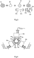
- the figure 3 schematically shows the different modes that can be transported in a single multimode optical fiber of an optical communication network according to one embodiment of the invention.
- Reference 21 represents the shape of the optical signal as propagated in a multimode optical fiber according to a cross section of said fiber.
- the first mode 30 is a TEM 00 type mode
- the second mode 32 is a TEM 01 type mode (or a combination of two TEM 01 type modes 32a and 32b)
- the third mode 34 is a TEM 02 mode (or a combination of three TEM 02 type modes 34a, 34b and 34c).
- Reference 21 thus represents the sum of the groups of modes 30, 32 and 34, themselves made up of modes 30, 32a and 32b, 34a and 34b and 34c.
- the described embodiment of the invention is only indicative as a solution for combining three equipment signals. According to other embodiments, more modes can be used to allow the combination of more than three equipment signals, depending on the needs of the network and the number of connected equipment. In addition, the types of modes used may be different.
- the figure 4 schematically represents a junction box of an optical communication network according to one embodiment of the invention.
- the junction box comprises three separators, a first separator 36a, a second separator 36b and a third separator 36c, as well as a right prism 38 having an equilateral triangle as its base.
- Each splitter 36a, 36b, 36c is connected to a multimode optical fiber, and receives an optical signal coming either from another neighboring junction box in the ring, or from a multiplexer / demultiplexer.
- the splitters 36a, 36b receive, for example, optical signals from other junction boxes and the splitter 36b can receive an optical signal from a multiplexer / demultiplexer.
- the splitters make it possible to divide the optical signals in order to transmit them to the other two splitters, as well as to receive the optical signals coming from the other two splitters.
- the first splitter 36a for example divides the signal received into two identical optical signals, forming optical beams, a first optical beam 40a and a second optical beam 42a.
- the first optical beam 40a is directed towards one face of the prism and is reflected towards the second splitter 36b.
- the second optical beam 42a is directed towards one face of the prism 38 and is reflected towards the third splitter 36c.
- the first splitter receives an optical beam 40b coming from the second splitter 36b and reflected by the prism 38 and an optical beam 42c coming from the third splitter 36c and reflected by the prism 38.
- the second splitter 36b sends a beam 44b optical to the third splitter 36c and receives an optical beam 44c from the third splitter 36c.
- the splitters can be configured so that the first splitter 36a and the third splitter 36c send / receive only the optical beams 42a and 42c.
- each splitter Upon reception of the optical beams from the other splitters, each splitter combines these optical beams and transmits the resulting optical signal to the optical fiber to which it is connected.
- the invention is not limited to the only embodiments described.
- other types of optical networks are possible.
- the configurations of the passive optical elements of multiplexers / demultiplexers as well as of the junction boxes can be modified as long as the function performed is identical and that only passive optical elements are used, because they allow the conservation of the modes of the optical signals. .
Landscapes
- Engineering & Computer Science (AREA)
- Computer Networks & Wireless Communication (AREA)
- Signal Processing (AREA)
- Physics & Mathematics (AREA)
- Electromagnetism (AREA)
- Computing Systems (AREA)
- Optical Communication System (AREA)
- Small-Scale Networks (AREA)
Claims (5)
- Eingebettetes optisches Ringkommunikationsnetzwerk, das angepasst ist, um eine Datenübertragung zwischen Ausrüstungen (12a-12h) zu ermöglichen, umfassend:- eine Reihe von Abzweiggehäusen (14a-14h), die jeweils einerseits durch multimodale und bidirektionale optische Fasern (16a-16h) derart direkt mit zwei anderen Abzweiggehäusen (14a-14h) verbunden sind, dass sie einen Ring bilden, und die angepasst sind, um andererseits durch multimodale und bidirektionale optische Fasern mit mindestens einem Multiplexer/Demultiplexer (18a, 18b, 18c) verbunden zu sein,- jede optische Faser (16a-16h) ist angepasst, um die Weiterleitung von optischen Signalen mindestens dreier unterschiedlicher Modi (32, 32, 34) zu ermöglichen,- jeder Multiplexer/Demultiplexer (18a, 18b, 18c) umfasst eine Vielzahl von passiven optischen Elementen und ermöglicht es, mindestens drei von den Ausrüstungen (12a-12h) stammende Ausrüstungssignale über ein modales Multiplexen in einer optischen Faser zu übertragen, oder die Modi eines von der optischen Faser stammenden optischen Signals zu mindestens drei Ausrüstungssignalen zu trennen,dadurch gekennzeichnet, dass:- die Abzweiggehäuse (14a-14h) jeweils drei Separatoren (36a, 36b, 36c) umfassen, mit denen die optischen Fasern verbunden sind, und die jeweils zu mindestens einem Prisma (38) gerichtet sind, wobei die Separatoren (36a, 36b, 36c) und das Prisma (38) konfiguriert sind, um ein aus einer optischen Faser stammendes, und in einen Separator eingehendes Signal zu den zwei anderen Separatoren zu richten, und damit jeder Separator die von den zwei anderen Separatoren stammenden Signale empfängt und diese Signale zur optischen Faser sendet, mit der er verbunden ist.
- Optisches Netzwerk nach Anspruch 1, dadurch gekennzeichnet, dass das Prisma (38) ein gerades Prisma ist, das als Basis ein gleichseitiges Dreieck aufweist.
- Optisches Netzwerk nach einem der Ansprüche 1 oder 2, dadurch gekennzeichnet, dass die optischen Multimodefasern (16a-16h) einen Kerndurchmesser von mehr als 50 µm aufweisen.
- Optisches Netzwerk nach einem der Ansprüche 1 bis 3, dadurch gekennzeichnet, dass die Abzweiggehäuse (14a-14h) und die optischen Fasern (16a-16h), die den Ring bilden, in einer selben Ebene angeordnet sind, und dadurch, dass das optische Netzwerk einen Sensor umfasst, der es ermöglicht, die Ausbreitungszeit von zwei optischen Signalen im Ring zu messen, wobei die zwei optischen Signale den Ring in einer entgegengesetzten Ausbreitungsrichtung durchlaufen.
- Luftfahrzeug, umfassend eine Vielzahl von Ausrüstungen (12a-12h), dadurch gekennzeichnet, dass es ein optisches Netzwerk (10) nach einem der Ansprüche 1 bis 4 für die Datenübertragung zwischen den Ausrüstungen (12a-12h) umfasst.
Applications Claiming Priority (2)
| Application Number | Priority Date | Filing Date | Title |
|---|---|---|---|
| FR1662226A FR3060248B1 (fr) | 2016-12-09 | 2016-12-09 | Reseau de communication embarque optique en anneau pour aeronef |
| PCT/FR2017/053419 WO2018104665A1 (fr) | 2016-12-09 | 2017-12-06 | Réseau de communication embarqué optique en anneau pour aéronef |
Publications (2)
| Publication Number | Publication Date |
|---|---|
| EP3552324A1 EP3552324A1 (de) | 2019-10-16 |
| EP3552324B1 true EP3552324B1 (de) | 2021-02-24 |
Family
ID=58992920
Family Applications (1)
| Application Number | Title | Priority Date | Filing Date |
|---|---|---|---|
| EP17821686.7A Active EP3552324B1 (de) | 2016-12-09 | 2017-12-06 | Eingebettetes optisches ringkommunikationsnetzwerk für flugzeug |
Country Status (5)
| Country | Link |
|---|---|
| US (1) | US10587342B2 (de) |
| EP (1) | EP3552324B1 (de) |
| CN (1) | CN110050418B (de) |
| FR (1) | FR3060248B1 (de) |
| WO (1) | WO2018104665A1 (de) |
Families Citing this family (2)
| Publication number | Priority date | Publication date | Assignee | Title |
|---|---|---|---|---|
| FR3129002A1 (fr) | 2021-11-05 | 2023-05-12 | Safran Electrical & Power | Dispositif de connexion par réattribution de canal de transmission à un réseau fibré passif de communication multiplexé embarqué pour aéronef |
| FR3129221A1 (fr) | 2021-11-15 | 2023-05-19 | Safran Electrical & Power | Multiplexeur optique hybride, démultiplexeur optique hybride associé et réseau de communication optique embarqué associé |
Family Cites Families (64)
| Publication number | Priority date | Publication date | Assignee | Title |
|---|---|---|---|---|
| US3840738A (en) * | 1973-05-09 | 1974-10-08 | Bell Telephone Labor Inc | Optical communications system with means for minimizing material dispersion |
| US4027945A (en) * | 1976-03-04 | 1977-06-07 | The United States Of America As Represented By The Secretary Of The Navy | Optical sliprings |
| US4278327A (en) * | 1979-11-26 | 1981-07-14 | Sperry Corporation | Liquid crystal matrices |
| US4366565A (en) * | 1980-07-29 | 1982-12-28 | Herskowitz Gerald J | Local area network optical fiber data communication |
| JPS57204507A (en) * | 1981-06-12 | 1982-12-15 | Nec Corp | Interference film type optical multiplexer and demultiplexer |
| US4431258A (en) * | 1981-12-15 | 1984-02-14 | Gte Laboratories Incorporated | Optical fiber transmission system and dichroic beam splitter therefor |
| US4516837A (en) * | 1983-02-22 | 1985-05-14 | Sperry Corporation | Electro-optical switch for unpolarized optical signals |
| FR2553243B1 (fr) * | 1983-10-11 | 1990-03-30 | Lignes Telegraph Telephon | Multiplexeur-demultiplexeur optique de longueurs d'onde pour liaison bidirectionnelle |
| US5271076A (en) * | 1992-10-05 | 1993-12-14 | The United States Of America As Represented By The Secretary Of The Navy | Method providing optimum optical trains alignment in a passive multi-channel fiber optic rotary joint |
| AU744431B2 (en) * | 1998-01-05 | 2002-02-21 | Corning Oca Corporation | Add/drop optical multiplexing device |
| US6014244A (en) * | 1998-06-18 | 2000-01-11 | Hewlett-Packard Company | Multi-port optical circulator utilizing imaging lens and correction optical element |
| US6253007B1 (en) * | 1998-07-08 | 2001-06-26 | Optical Switch Corporation | Method and apparatus for connecting optical fibers |
| JP3586586B2 (ja) * | 1999-05-24 | 2004-11-10 | 日本電気株式会社 | 光波リングシステム |
| US6363186B1 (en) * | 2000-02-29 | 2002-03-26 | Nec Research Institute, Inc. | X-cube integrated solid optics component |
| CN1446438A (zh) * | 2000-05-16 | 2003-10-01 | 福图瑞斯有限公司 | 可重新配置的光开关 |
| US6941072B2 (en) * | 2000-10-17 | 2005-09-06 | Jds Uniphase Corporation | Compact optical multiplexer/demultiplexer |
| AU2002245067A1 (en) * | 2000-11-01 | 2002-07-24 | Intel Corporation | System and method for collimating and redirecting beams |
| JP2002169022A (ja) * | 2000-12-04 | 2002-06-14 | Nippon Sheet Glass Co Ltd | 光学素子およびそれを用いた分光装置および集積光学装置 |
| US7042631B2 (en) * | 2001-01-04 | 2006-05-09 | Coherent Technologies, Inc. | Power scalable optical systems for generating, transporting, and delivering high power, high quality, laser beams |
| US6597829B2 (en) * | 2001-04-27 | 2003-07-22 | Robert H. Cormack | 1xN optical fiber switch |
| US7496257B2 (en) * | 2001-07-03 | 2009-02-24 | Brown University Research Foundation | Method and apparatus for detecting multiple optical wavelengths |
| US6847450B2 (en) * | 2001-07-27 | 2005-01-25 | Oplink Communications, Inc. | System and method for optical multiplexing and/or demultiplexing |
| US6571033B2 (en) * | 2001-09-28 | 2003-05-27 | Corning Incorporated | Optical signal device |
| JP3517406B2 (ja) * | 2001-10-10 | 2004-04-12 | サンテック株式会社 | 波長可変合分波器及び波長ルーティング装置 |
| US6775432B2 (en) * | 2001-10-19 | 2004-08-10 | Santanu Basu | Method and apparatus for optical wavelength demultiplexing, multiplexing and routing |
| US6751366B2 (en) * | 2002-02-12 | 2004-06-15 | Oplink Communications, Inc. | Multi-port circulator |
| US7606494B1 (en) * | 2002-06-04 | 2009-10-20 | Broadwing Corporation | Optical transmission systems, devices, and methods |
| US20040005115A1 (en) * | 2002-07-02 | 2004-01-08 | Luo Xin Simon | Optoelectronic add/drop multiplexer |
| CN100483975C (zh) * | 2003-07-08 | 2009-04-29 | 中国科学技术大学 | 量子网络寻址方法及量子网络路由器 |
| US7415210B2 (en) * | 2003-07-28 | 2008-08-19 | Allied Telesis, Inc. | Bidirectional optical signal multiplexer/demultiplexer |
| US7142747B2 (en) * | 2003-08-12 | 2006-11-28 | Moog Inc. | Fiber optic rotary joint and associated alignment method |
| FR2860077A1 (fr) * | 2003-09-22 | 2005-03-25 | Optogone Sa | Filtre spatial de phase pour faisceau optique, systeme et procede correspondant |
| US7440654B2 (en) * | 2003-11-28 | 2008-10-21 | Mcgill University | Wavelength multiplexer/demultiplexer comprising an optically dispersive stratified body |
| US7058257B2 (en) * | 2003-12-30 | 2006-06-06 | Lightwaves 2020, Inc. | Miniature WDM add/drop multiplexer and method of manufacture thereof |
| US7305155B2 (en) * | 2004-03-26 | 2007-12-04 | Nippon Sheet Glass Company, Limited | Optical element and wavelength separator using the same |
| KR100594902B1 (ko) * | 2004-04-27 | 2006-06-30 | (주)싸이버트론 | 링 타입 광 전송 시스템 |
| US7403677B1 (en) * | 2005-05-11 | 2008-07-22 | Agiltron, Inc. | Fiberoptic reconfigurable devices with beam shaping for low-voltage operation |
| US7286730B2 (en) * | 2006-03-15 | 2007-10-23 | Avanex Corporation | Optical switch having angle tuning elements and multiple-fiber collimators |
| US7805033B2 (en) * | 2006-09-27 | 2010-09-28 | Xyratex Technology Limited | Optical wavelength division multiplexed multiplexer/demultiplexer for an optical printed circuit board and a method of manufacturing the same |
| DE102007013923B4 (de) * | 2006-12-22 | 2012-02-02 | Schleifring Und Apparatebau Gmbh | Mehrkanaliger optischer Drehübertrager mit hoher Rückflußdämpfung |
| US7843644B1 (en) * | 2007-02-01 | 2010-11-30 | Alliance Fiber Optic Products, Inc. | Compact free-space WDM device with one-sided input/output ports |
| US8538210B2 (en) * | 2007-02-01 | 2013-09-17 | Alliance Fiber Optic Products, Inc. | Micro free-space WDM device |
| DE102007029503A1 (de) * | 2007-06-25 | 2009-01-02 | Schleifring Und Apparatebau Gmbh | Optischer Drehübertrager mit kurzer Baulänge |
| US8515278B2 (en) * | 2008-10-31 | 2013-08-20 | Futurewei Technologies, Inc. | Passive optical networks with mode coupling receivers |
| EP2362948B1 (de) * | 2008-12-11 | 2019-02-20 | Moog Inc. | Hochleistungs-kollimatorlinsen-anordnungen und verfahren zur reduzierung der optischen leistungsdichte in kollimatorlinsenanordnungen |
| CN101729942B (zh) * | 2009-11-26 | 2012-11-07 | 上海大学 | 波分复用无源光网络实现环形局域网系统和方法 |
| JP2014500977A (ja) * | 2010-10-29 | 2014-01-16 | ヒューレット−パッカード デベロップメント カンパニー エル.ピー. | スターカプラを用いて実施される光相互接続ファブリック |
| TWI468758B (zh) * | 2010-12-16 | 2015-01-11 | Hon Hai Prec Ind Co Ltd | 光纖連接器 |
| US8417075B2 (en) * | 2011-01-05 | 2013-04-09 | Princetel, Inc. | Multi-channel electro-magnetic rotary joint using a trapezoidal metamaterial de-rotating mechanism |
| US9594216B1 (en) * | 2011-06-08 | 2017-03-14 | Alliance Fiber Optic Products, Inc. | Fiber optical switches |
| EP2745164A4 (de) * | 2011-09-30 | 2015-05-20 | Hewlett Packard Development Co | Optischer leistungsteiler mit zickzack |
| US9435959B2 (en) * | 2012-04-26 | 2016-09-06 | Acacia Communications, Inc. | Coupling of fiber optics to planar grating couplers |
| EP2665212B1 (de) * | 2012-05-16 | 2016-11-30 | Alcatel Lucent | Optisches Datenübertragungssystem |
| CN102684794A (zh) * | 2012-06-06 | 2012-09-19 | 苏州旭创科技有限公司 | 应用于高速并行长距离传输的新型波分复用解复用光组件 |
| EP2708926A1 (de) * | 2012-09-13 | 2014-03-19 | u2t Photonics AG | Optische Vorrichtung |
| US9319139B2 (en) * | 2013-03-11 | 2016-04-19 | Futurewei Technologies, Inc. | Long distance multi-mode communication |
| JP6163821B2 (ja) * | 2013-03-27 | 2017-07-19 | 三菱電機株式会社 | 光送信装置および光受信装置 |
| US9348091B2 (en) * | 2013-12-20 | 2016-05-24 | Finisar Corporation | Multiplexer/demultiplexer based on diffraction and reflection |
| US9551833B1 (en) * | 2014-04-18 | 2017-01-24 | Alliance Fiber Optic Products, Inc. | Ultra compact free-space multiplexer/demultiplexer |
| US9989706B2 (en) * | 2014-12-31 | 2018-06-05 | OW Holding Inc. | Method and apparatus for providing multiport free-space wavelength-division multiplexing (WDM) device using a prism |
| US9401773B1 (en) * | 2015-03-04 | 2016-07-26 | Alliance Fiber Optic Products, Inc. | Compact multi-channel WDM devices for high-speed data communications |
| US20180017735A1 (en) * | 2016-07-13 | 2018-01-18 | Futurewei Technologies, Inc. | Wavelength Division Multiplexer/Demultiplexer with Flexibility of Optical Adjustment |
| US10313045B2 (en) * | 2016-11-17 | 2019-06-04 | Alliance Fiber Optic Products, Inc. | Wavelength-division multiplexing optical assembly with increased lane density |
| US10551569B2 (en) * | 2017-02-02 | 2020-02-04 | Alliance Fiber Optic Products, Inc. | Wavelength-division multiplexing optical assembly with multiple collimator sets |
-
2016
- 2016-12-09 FR FR1662226A patent/FR3060248B1/fr active Active
-
2017
- 2017-12-06 CN CN201780075119.7A patent/CN110050418B/zh active Active
- 2017-12-06 EP EP17821686.7A patent/EP3552324B1/de active Active
- 2017-12-06 US US16/466,605 patent/US10587342B2/en active Active
- 2017-12-06 WO PCT/FR2017/053419 patent/WO2018104665A1/fr not_active Ceased
Non-Patent Citations (1)
| Title |
|---|
| None * |
Also Published As
| Publication number | Publication date |
|---|---|
| CN110050418B (zh) | 2020-08-21 |
| US20190393960A1 (en) | 2019-12-26 |
| FR3060248B1 (fr) | 2019-03-15 |
| FR3060248A1 (fr) | 2018-06-15 |
| EP3552324A1 (de) | 2019-10-16 |
| WO2018104665A1 (fr) | 2018-06-14 |
| CN110050418A (zh) | 2019-07-23 |
| US10587342B2 (en) | 2020-03-10 |
Similar Documents
| Publication | Publication Date | Title |
|---|---|---|
| US20200052786A1 (en) | Methods and systems relating to optical networks | |
| EP3491438B1 (de) | Multispektraler optischer koppler mit niedrigen empfangsverlusten | |
| FR2932932A1 (fr) | Systeme optique multiplexe en longueur d'ondes avec fibres optiques multimodes | |
| EP1341013A1 (de) | Optische Drehverbindung | |
| EP1014607B1 (de) | Verfahren zum Reduzieren von Kreuzphasenmodulation-induzierter Intensitätsverzerrung in einem optischen WDM Übertragungssystem | |
| EP3552324B1 (de) | Eingebettetes optisches ringkommunikationsnetzwerk für flugzeug | |
| EP0984572B1 (de) | Vorrichtung zur Polarisationsdispersionskompensation den Kanälen in einem WDM-Signal | |
| FR3129221A1 (fr) | Multiplexeur optique hybride, démultiplexeur optique hybride associé et réseau de communication optique embarqué associé | |
| EP4109158B1 (de) | Optronisches sende-/empfangsmodul | |
| EP1459464B1 (de) | Optisches freiausbreitungsübertragungssystem | |
| EP4070479B1 (de) | Passives optisches kommunikationsnetz und flugzeug mit diesem netz | |
| EP1428333A2 (de) | Optisches ringnetzwerk mit doppeltem optischem bus | |
| Hornsteiner | Fiber Optic Technology Trends in Data Transmission: Digitalization of data advance the need for constant upgrading of data networks | |
| FR3006835A1 (fr) | Systemes de communication bidirectionnelle continue par liaison atmospherique | |
| EP3900238A1 (de) | Rekonfigurierbare optische rückwandplatine | |
| EP4097423A1 (de) | System zum messen einer mehrzahl von physikalischen parametern an einem messpunkt mit einer optischen multimode-faser | |
| WO2023079248A1 (fr) | Dispositif de connexion par reattribution de canal de transmission a un reseau fibre passif de communication multiplexe embarque pour aeronef | |
| EP0509434B1 (de) | Übertragungsanlage mit fernüberwachter optischer Verbindung | |
| FR3139396A1 (fr) | Routeur optique pour la distribution de signaux optiques | |
| FR2718588A1 (fr) | Dispositif d'égalisation, en fonction de la longueur d'onde, d'un gain appliqué à un signal optique. | |
| FR2703541A1 (fr) | Dispositif d'interrogation et d'analyse d'un réseau de capteurs interférométriques de mesure en lumière polarisée. | |
| FR2921218A1 (fr) | Liaison optique et procede de transmission de donnees. |
Legal Events
| Date | Code | Title | Description |
|---|---|---|---|
| STAA | Information on the status of an ep patent application or granted ep patent |
Free format text: STATUS: UNKNOWN |
|
| STAA | Information on the status of an ep patent application or granted ep patent |
Free format text: STATUS: THE INTERNATIONAL PUBLICATION HAS BEEN MADE |
|
| PUAI | Public reference made under article 153(3) epc to a published international application that has entered the european phase |
Free format text: ORIGINAL CODE: 0009012 |
|
| STAA | Information on the status of an ep patent application or granted ep patent |
Free format text: STATUS: REQUEST FOR EXAMINATION WAS MADE |
|
| 17P | Request for examination filed |
Effective date: 20190611 |
|
| AK | Designated contracting states |
Kind code of ref document: A1 Designated state(s): AL AT BE BG CH CY CZ DE DK EE ES FI FR GB GR HR HU IE IS IT LI LT LU LV MC MK MT NL NO PL PT RO RS SE SI SK SM TR |
|
| AX | Request for extension of the european patent |
Extension state: BA ME |
|
| DAV | Request for validation of the european patent (deleted) | ||
| DAX | Request for extension of the european patent (deleted) | ||
| GRAP | Despatch of communication of intention to grant a patent |
Free format text: ORIGINAL CODE: EPIDOSNIGR1 |
|
| STAA | Information on the status of an ep patent application or granted ep patent |
Free format text: STATUS: GRANT OF PATENT IS INTENDED |
|
| INTG | Intention to grant announced |
Effective date: 20201007 |
|
| GRAS | Grant fee paid |
Free format text: ORIGINAL CODE: EPIDOSNIGR3 |
|
| GRAA | (expected) grant |
Free format text: ORIGINAL CODE: 0009210 |
|
| STAA | Information on the status of an ep patent application or granted ep patent |
Free format text: STATUS: THE PATENT HAS BEEN GRANTED |
|
| AK | Designated contracting states |
Kind code of ref document: B1 Designated state(s): AL AT BE BG CH CY CZ DE DK EE ES FI FR GB GR HR HU IE IS IT LI LT LU LV MC MK MT NL NO PL PT RO RS SE SI SK SM TR |
|
| REG | Reference to a national code |
Ref country code: CH Ref legal event code: EP |
|
| REG | Reference to a national code |
Ref country code: DE Ref legal event code: R096 Ref document number: 602017033470 Country of ref document: DE |
|
| REG | Reference to a national code |
Ref country code: AT Ref legal event code: REF Ref document number: 1365818 Country of ref document: AT Kind code of ref document: T Effective date: 20210315 |
|
| REG | Reference to a national code |
Ref country code: IE Ref legal event code: FG4D Free format text: LANGUAGE OF EP DOCUMENT: FRENCH |
|
| REG | Reference to a national code |
Ref country code: LT Ref legal event code: MG9D |
|
| REG | Reference to a national code |
Ref country code: NL Ref legal event code: MP Effective date: 20210224 |
|
| PG25 | Lapsed in a contracting state [announced via postgrant information from national office to epo] |
Ref country code: LT Free format text: LAPSE BECAUSE OF FAILURE TO SUBMIT A TRANSLATION OF THE DESCRIPTION OR TO PAY THE FEE WITHIN THE PRESCRIBED TIME-LIMIT Effective date: 20210224 Ref country code: BG Free format text: LAPSE BECAUSE OF FAILURE TO SUBMIT A TRANSLATION OF THE DESCRIPTION OR TO PAY THE FEE WITHIN THE PRESCRIBED TIME-LIMIT Effective date: 20210524 Ref country code: HR Free format text: LAPSE BECAUSE OF FAILURE TO SUBMIT A TRANSLATION OF THE DESCRIPTION OR TO PAY THE FEE WITHIN THE PRESCRIBED TIME-LIMIT Effective date: 20210224 Ref country code: FI Free format text: LAPSE BECAUSE OF FAILURE TO SUBMIT A TRANSLATION OF THE DESCRIPTION OR TO PAY THE FEE WITHIN THE PRESCRIBED TIME-LIMIT Effective date: 20210224 Ref country code: GR Free format text: LAPSE BECAUSE OF FAILURE TO SUBMIT A TRANSLATION OF THE DESCRIPTION OR TO PAY THE FEE WITHIN THE PRESCRIBED TIME-LIMIT Effective date: 20210525 Ref country code: PT Free format text: LAPSE BECAUSE OF FAILURE TO SUBMIT A TRANSLATION OF THE DESCRIPTION OR TO PAY THE FEE WITHIN THE PRESCRIBED TIME-LIMIT Effective date: 20210624 Ref country code: NO Free format text: LAPSE BECAUSE OF FAILURE TO SUBMIT A TRANSLATION OF THE DESCRIPTION OR TO PAY THE FEE WITHIN THE PRESCRIBED TIME-LIMIT Effective date: 20210524 |
|
| REG | Reference to a national code |
Ref country code: AT Ref legal event code: MK05 Ref document number: 1365818 Country of ref document: AT Kind code of ref document: T Effective date: 20210224 |
|
| PG25 | Lapsed in a contracting state [announced via postgrant information from national office to epo] |
Ref country code: RS Free format text: LAPSE BECAUSE OF FAILURE TO SUBMIT A TRANSLATION OF THE DESCRIPTION OR TO PAY THE FEE WITHIN THE PRESCRIBED TIME-LIMIT Effective date: 20210224 Ref country code: NL Free format text: LAPSE BECAUSE OF FAILURE TO SUBMIT A TRANSLATION OF THE DESCRIPTION OR TO PAY THE FEE WITHIN THE PRESCRIBED TIME-LIMIT Effective date: 20210224 Ref country code: LV Free format text: LAPSE BECAUSE OF FAILURE TO SUBMIT A TRANSLATION OF THE DESCRIPTION OR TO PAY THE FEE WITHIN THE PRESCRIBED TIME-LIMIT Effective date: 20210224 Ref country code: PL Free format text: LAPSE BECAUSE OF FAILURE TO SUBMIT A TRANSLATION OF THE DESCRIPTION OR TO PAY THE FEE WITHIN THE PRESCRIBED TIME-LIMIT Effective date: 20210224 Ref country code: SE Free format text: LAPSE BECAUSE OF FAILURE TO SUBMIT A TRANSLATION OF THE DESCRIPTION OR TO PAY THE FEE WITHIN THE PRESCRIBED TIME-LIMIT Effective date: 20210224 |
|
| PG25 | Lapsed in a contracting state [announced via postgrant information from national office to epo] |
Ref country code: IS Free format text: LAPSE BECAUSE OF FAILURE TO SUBMIT A TRANSLATION OF THE DESCRIPTION OR TO PAY THE FEE WITHIN THE PRESCRIBED TIME-LIMIT Effective date: 20210624 |
|
| PG25 | Lapsed in a contracting state [announced via postgrant information from national office to epo] |
Ref country code: EE Free format text: LAPSE BECAUSE OF FAILURE TO SUBMIT A TRANSLATION OF THE DESCRIPTION OR TO PAY THE FEE WITHIN THE PRESCRIBED TIME-LIMIT Effective date: 20210224 Ref country code: CZ Free format text: LAPSE BECAUSE OF FAILURE TO SUBMIT A TRANSLATION OF THE DESCRIPTION OR TO PAY THE FEE WITHIN THE PRESCRIBED TIME-LIMIT Effective date: 20210224 Ref country code: SM Free format text: LAPSE BECAUSE OF FAILURE TO SUBMIT A TRANSLATION OF THE DESCRIPTION OR TO PAY THE FEE WITHIN THE PRESCRIBED TIME-LIMIT Effective date: 20210224 Ref country code: AT Free format text: LAPSE BECAUSE OF FAILURE TO SUBMIT A TRANSLATION OF THE DESCRIPTION OR TO PAY THE FEE WITHIN THE PRESCRIBED TIME-LIMIT Effective date: 20210224 |
|
| REG | Reference to a national code |
Ref country code: DE Ref legal event code: R097 Ref document number: 602017033470 Country of ref document: DE |
|
| PG25 | Lapsed in a contracting state [announced via postgrant information from national office to epo] |
Ref country code: DK Free format text: LAPSE BECAUSE OF FAILURE TO SUBMIT A TRANSLATION OF THE DESCRIPTION OR TO PAY THE FEE WITHIN THE PRESCRIBED TIME-LIMIT Effective date: 20210224 Ref country code: SK Free format text: LAPSE BECAUSE OF FAILURE TO SUBMIT A TRANSLATION OF THE DESCRIPTION OR TO PAY THE FEE WITHIN THE PRESCRIBED TIME-LIMIT Effective date: 20210224 Ref country code: RO Free format text: LAPSE BECAUSE OF FAILURE TO SUBMIT A TRANSLATION OF THE DESCRIPTION OR TO PAY THE FEE WITHIN THE PRESCRIBED TIME-LIMIT Effective date: 20210224 |
|
| PLBE | No opposition filed within time limit |
Free format text: ORIGINAL CODE: 0009261 |
|
| STAA | Information on the status of an ep patent application or granted ep patent |
Free format text: STATUS: NO OPPOSITION FILED WITHIN TIME LIMIT |
|
| PG25 | Lapsed in a contracting state [announced via postgrant information from national office to epo] |
Ref country code: AL Free format text: LAPSE BECAUSE OF FAILURE TO SUBMIT A TRANSLATION OF THE DESCRIPTION OR TO PAY THE FEE WITHIN THE PRESCRIBED TIME-LIMIT Effective date: 20210224 Ref country code: ES Free format text: LAPSE BECAUSE OF FAILURE TO SUBMIT A TRANSLATION OF THE DESCRIPTION OR TO PAY THE FEE WITHIN THE PRESCRIBED TIME-LIMIT Effective date: 20210224 |
|
| PGFP | Annual fee paid to national office [announced via postgrant information from national office to epo] |
Ref country code: DE Payment date: 20211117 Year of fee payment: 5 |
|
| 26N | No opposition filed |
Effective date: 20211125 |
|
| PG25 | Lapsed in a contracting state [announced via postgrant information from national office to epo] |
Ref country code: SI Free format text: LAPSE BECAUSE OF FAILURE TO SUBMIT A TRANSLATION OF THE DESCRIPTION OR TO PAY THE FEE WITHIN THE PRESCRIBED TIME-LIMIT Effective date: 20210224 |
|
| PG25 | Lapsed in a contracting state [announced via postgrant information from national office to epo] |
Ref country code: IT Free format text: LAPSE BECAUSE OF FAILURE TO SUBMIT A TRANSLATION OF THE DESCRIPTION OR TO PAY THE FEE WITHIN THE PRESCRIBED TIME-LIMIT Effective date: 20210224 |
|
| PG25 | Lapsed in a contracting state [announced via postgrant information from national office to epo] |
Ref country code: IS Free format text: LAPSE BECAUSE OF FAILURE TO SUBMIT A TRANSLATION OF THE DESCRIPTION OR TO PAY THE FEE WITHIN THE PRESCRIBED TIME-LIMIT Effective date: 20210624 |
|
| PG25 | Lapsed in a contracting state [announced via postgrant information from national office to epo] |
Ref country code: MC Free format text: LAPSE BECAUSE OF FAILURE TO SUBMIT A TRANSLATION OF THE DESCRIPTION OR TO PAY THE FEE WITHIN THE PRESCRIBED TIME-LIMIT Effective date: 20210224 |
|
| REG | Reference to a national code |
Ref country code: CH Ref legal event code: PL |
|
| REG | Reference to a national code |
Ref country code: BE Ref legal event code: MM Effective date: 20211231 |
|
| PG25 | Lapsed in a contracting state [announced via postgrant information from national office to epo] |
Ref country code: LU Free format text: LAPSE BECAUSE OF NON-PAYMENT OF DUE FEES Effective date: 20211206 Ref country code: IE Free format text: LAPSE BECAUSE OF NON-PAYMENT OF DUE FEES Effective date: 20211206 |
|
| PG25 | Lapsed in a contracting state [announced via postgrant information from national office to epo] |
Ref country code: BE Free format text: LAPSE BECAUSE OF NON-PAYMENT OF DUE FEES Effective date: 20211231 |
|
| PG25 | Lapsed in a contracting state [announced via postgrant information from national office to epo] |
Ref country code: LI Free format text: LAPSE BECAUSE OF NON-PAYMENT OF DUE FEES Effective date: 20211231 Ref country code: CH Free format text: LAPSE BECAUSE OF NON-PAYMENT OF DUE FEES Effective date: 20211231 |
|
| PG25 | Lapsed in a contracting state [announced via postgrant information from national office to epo] |
Ref country code: CY Free format text: LAPSE BECAUSE OF FAILURE TO SUBMIT A TRANSLATION OF THE DESCRIPTION OR TO PAY THE FEE WITHIN THE PRESCRIBED TIME-LIMIT Effective date: 20210224 |
|
| REG | Reference to a national code |
Ref country code: DE Ref legal event code: R119 Ref document number: 602017033470 Country of ref document: DE |
|
| PG25 | Lapsed in a contracting state [announced via postgrant information from national office to epo] |
Ref country code: HU Free format text: LAPSE BECAUSE OF FAILURE TO SUBMIT A TRANSLATION OF THE DESCRIPTION OR TO PAY THE FEE WITHIN THE PRESCRIBED TIME-LIMIT; INVALID AB INITIO Effective date: 20171206 |
|
| PG25 | Lapsed in a contracting state [announced via postgrant information from national office to epo] |
Ref country code: DE Free format text: LAPSE BECAUSE OF NON-PAYMENT OF DUE FEES Effective date: 20230701 |
|
| PG25 | Lapsed in a contracting state [announced via postgrant information from national office to epo] |
Ref country code: MK Free format text: LAPSE BECAUSE OF FAILURE TO SUBMIT A TRANSLATION OF THE DESCRIPTION OR TO PAY THE FEE WITHIN THE PRESCRIBED TIME-LIMIT Effective date: 20210224 |
|
| PG25 | Lapsed in a contracting state [announced via postgrant information from national office to epo] |
Ref country code: MT Free format text: LAPSE BECAUSE OF FAILURE TO SUBMIT A TRANSLATION OF THE DESCRIPTION OR TO PAY THE FEE WITHIN THE PRESCRIBED TIME-LIMIT Effective date: 20210224 |
|
| PG25 | Lapsed in a contracting state [announced via postgrant information from national office to epo] |
Ref country code: TR Free format text: LAPSE BECAUSE OF FAILURE TO SUBMIT A TRANSLATION OF THE DESCRIPTION OR TO PAY THE FEE WITHIN THE PRESCRIBED TIME-LIMIT Effective date: 20210224 |
|
| PGFP | Annual fee paid to national office [announced via postgrant information from national office to epo] |
Ref country code: GB Payment date: 20251229 Year of fee payment: 9 |
|
| PGFP | Annual fee paid to national office [announced via postgrant information from national office to epo] |
Ref country code: FR Payment date: 20251222 Year of fee payment: 9 |