EP3552501A1 - Dispositif et procédé d'inspection d'une surface frontale d'un article à fumer en forme de tige - Google Patents
Dispositif et procédé d'inspection d'une surface frontale d'un article à fumer en forme de tige Download PDFInfo
- Publication number
- EP3552501A1 EP3552501A1 EP19165376.5A EP19165376A EP3552501A1 EP 3552501 A1 EP3552501 A1 EP 3552501A1 EP 19165376 A EP19165376 A EP 19165376A EP 3552501 A1 EP3552501 A1 EP 3552501A1
- Authority
- EP
- European Patent Office
- Prior art keywords
- camera
- smoking article
- position sensor
- signal
- products
- Prior art date
- Legal status (The legal status is an assumption and is not a legal conclusion. Google has not performed a legal analysis and makes no representation as to the accuracy of the status listed.)
- Granted
Links
Images

Classifications
-
- A—HUMAN NECESSITIES
- A24—TOBACCO; CIGARS; CIGARETTES; SIMULATED SMOKING DEVICES; SMOKERS' REQUISITES
- A24C—MACHINES FOR MAKING CIGARS OR CIGARETTES
- A24C5/00—Making cigarettes; Making tipping materials for, or attaching filters or mouthpieces to, cigars or cigarettes
- A24C5/32—Separating, ordering, counting or examining cigarettes; Regulating the feeding of tobacco according to rod or cigarette condition
- A24C5/34—Examining cigarettes or the rod, e.g. for regulating the feeding of tobacco; Removing defective cigarettes
- A24C5/3412—Examining cigarettes or the rod, e.g. for regulating the feeding of tobacco; Removing defective cigarettes by means of light, radiation or electrostatic fields
-
- A—HUMAN NECESSITIES
- A24—TOBACCO; CIGARS; CIGARETTES; SIMULATED SMOKING DEVICES; SMOKERS' REQUISITES
- A24C—MACHINES FOR MAKING CIGARS OR CIGARETTES
- A24C5/00—Making cigarettes; Making tipping materials for, or attaching filters or mouthpieces to, cigars or cigarettes
- A24C5/32—Separating, ordering, counting or examining cigarettes; Regulating the feeding of tobacco according to rod or cigarette condition
- A24C5/34—Examining cigarettes or the rod, e.g. for regulating the feeding of tobacco; Removing defective cigarettes
-
- A—HUMAN NECESSITIES
- A24—TOBACCO; CIGARS; CIGARETTES; SIMULATED SMOKING DEVICES; SMOKERS' REQUISITES
- A24C—MACHINES FOR MAKING CIGARS OR CIGARETTES
- A24C5/00—Making cigarettes; Making tipping materials for, or attaching filters or mouthpieces to, cigars or cigarettes
- A24C5/32—Separating, ordering, counting or examining cigarettes; Regulating the feeding of tobacco according to rod or cigarette condition
- A24C5/322—Transporting cigarettes during manufacturing
- A24C5/326—Transporting cigarettes during manufacturing with lateral transferring means
Definitions
- the present invention relates to a device for inspecting an end face of a rod-shaped smoking article having the features of the preamble of claim 1 and a method for inspecting an end face of a rod-shaped smoking article having the features of the preamble of claim 10.
- Rod shaped smoking articles are e.g. Cigarettes, cigarillos, Heat Not Burn products (HNB products) or similar products intended for the inhalation of a consumer.
- HNB products Heat Not Burn products
- Rod-shaped smoking articles are also precursors of smoking articles to understand such. Filter rods, tobacco sticks with a by a strip strip shape-stabilized tobacco material, segments of HNB products, such as tubular cooling sections, taste-affecting segments or the like to see, which are subsequently connected to other precursors to a finished rod-shaped smoking article.
- the rod-shaped smoking articles and precursors of the smoking articles are referred to hereinafter as "products" in the description for the sake of simplicity.
- a conveyor which comprises a format section in which an endless strand of material, such as a tobacco or tow, is placed on an endless web of casing material, which is then folded over and adhered to the edge sides of the casing material is fixed to a solid strand.
- This dimensionally stable strand is subsequently cut into cylindrical or rod-shaped products having a predetermined rod length by means of a rotating knife carrier with a plurality of radially outwardly projecting knives.
- the products are pushed on a guide device as a strand of adjoining individual products in a longitudinal axial transport direction or strand direction to a takeover point or alternatively also actively transported.
- the longitudinal conveyor is formed by a rotationally driven drum, which has a plurality of protruding, rotatably mounted lever arms. On each of the lever arms, one or more axially spaced receptacles are provided, to which one or more aligned parallel to the supplied products, can be acted upon with negative pressure channels or troughs.
- the lever arms perform during the circulation of the drum for an outside observer to an opposite rotational movement of the drum rotational movement, so that the recordings are guided on an elliptical trajectory.
- the recordings themselves are held during the orbital movement of the drum and the lever arms by means of a mechanism in a constant, preferably horizontal orientation, which is a Ensures alignment of the products held in the recordings, wherein the longitudinal axes of the products are always preferably parallel to the transport direction of the supplied strand.
- the receptacles with the grooves provided thereon are guided past the products in a transfer point so close to the products that the products are sucked in by the negative pressure acting in the grooves and removed by the conveyor.
- the products are moved to a transfer point, in which the channels with the products held therein perform a preferably purely transverse movement relative to their longitudinal axes or to the transport direction of the guide device.
- a transverse conveyor which is also formed by a rotatably drivable drum, but is arranged with its axis of rotation in a preferably rectangular arrangement to the axis of rotation of the longitudinal conveyor.
- a plurality of likewise be acted upon by negative pressure and aligned parallel to the axis of rotation of the transverse conveyor grooves are provided, which are passed in the transfer point so close to the grooves of the longitudinal conveyor and the products held therein, that the products across taken over their longitudinal axis and further transported.
- a problem with the transport of the products is that the grooves of the longitudinal conveyor receivers have to be moved at the takeover point at a speed higher than the speed of the supplied products (also called overspeed) so that the products fed to the longitudinal conveyor on the guide means will not damming or colliding with the subsequent product during the takeover.
- the overspeed is also dependent on the rod length of the products, since the speed of the longitudinal conveyor of the conveyors is the same for the transport of products of different rod length, and the strand speed of the supplied products must be matched to a predetermined number of products to be accepted per unit time. For these reasons, the products are taken under unfavorable conditions at up to twice the overspeed compared to the feed rate of the products.
- the grooves themselves also have a certain surface roughness, which determines the effective frictional forces between the grooves and the products in the acquisition.
- the products are accelerated in the takeover jerky, which act on the products certain forces in the axial and radial directions, which are among other things responsible for the head failure of the products.
- the overspeed should therefore be as low as possible or only a small amount higher than the feed rate of the products.
- the orientation of the products in the grooves of the cross conveyor is especially of great importance when the products are transported in double length and cut in this position on the cross conveyor in products of simple length, since the location of the products in the gutters of the cross conveyor at a fixed cutting edge then also influenced the lengths of the cut, simply long products decisively.
- a sensor based on imaging sensor face sensor is provided, for example, in filter manufacturing.
- the products are typically subjected to optical inspection by means of a camera adapted to receive images of an end face of the products. The images taken by the camera are then evaluated by an electronic signal processing device.
- a measuring device for on-line measurement is for example from EP 2 677 273 B1 known.
- the measuring device is designed for the optical examination of the end faces of products conveyed in a transverse conveyor and, in one embodiment, proposes the quality inspection by means of a digital camera for 2D recordings.
- Possible alignment of the products within the wells of the drum in the axial direction typically occurs towards the center of the dispensing drum.
- the distance between the end face of a product and the camera changes with a change in length of the products or a format change.
- the distance between the camera and the end face to be inspected is different from before the change in length or the format change, and a valid measurement with the camera is not possible.
- the camera has to be readjusted after each format change.
- An object of the invention is to provide an apparatus and a corresponding method which provide an effective and Ensure reliable quality assurance through reliable optical testing of the products.
- a position sensor directed at a measuring position which generates a signal when conveying the smoking article through the measuring position and forwards it to the camera, and the camera can be triggered in response to the signal of the position sensor and / or moved into a triggering position is.
- the invention has recognized that the distance between the camera and the smoking article must comply with a specified value in order to generate a sufficiently sharp image with the camera for the evaluation. Triggering the camera in response to the position sensor signal ensures that the camera will only take pictures under the condition that the smoking article is in a defined position that corresponds to the measuring position at the time the position sensor senses it. The signal indicating that the smoking article is in the measurement position is then forwarded to the camera to initiate a capture and / or to provide a condition favorable to capture, where a sharp image can be taken.
- the sensing can be realized in different ways, eg by referencing directly to the smoking article and / or to a machine part coupled to the position of the smoking article becomes.
- the camera can be arranged and / or moved to the release position such that the distance between the camera and the smoking article corresponds to the specified distance in order to be able to record a clear image with the camera.
- the procedure in the release position is used for the exact adjustment of the distance and ensures a sharp image of the end face.
- a fluctuation of the position of the article, for example, during the acquisition, can thus be taken into account when taking the picture.
- a variation of the length of the smoking article can thus be compensated without further effort.
- a customary in the prior art manual adjustment of the triggering position on the corresponding length of the smoking article is therefore not necessary, ie the device and the corresponding method according to the invention work independently of format.
- the acquisition of an image by the camera can be carried out so that the camera on the basis of the generated signal, the exposure over a certain exposure time, for example in the range of fractions of seconds, guaranteed, and during the illumination, a lighting illuminates the inspected end face.
- the illumination means may comprise an LED.
- the illumination duration may preferably be smaller than the exposure time.
- the camera triggers at the same time to the input of the signal recording of an image of the detected by the position sensor smoking article, in the case of the fixed distance for a sharp image corresponding distance between the camera and smoking article with a sharp image of each passed on the position sensor smoking article with to record the camera.
- the smoking article passes through the focal plane of the objective the camera, ie the measuring position is in the focal plane of the camera or the triggering position is spaced from the measuring position by a value corresponding to the focal plane.
- a simultaneous triggering of a recording thus causes a sharp image of the sensed or detected smoking article.
- the simultaneous trigger signal-related time differences are to be understood, which may result, for example, by the signal line from the position sensor to the camera or by the signal processing in the position sensor and / or the camera and may for example be in the range of a few microseconds.
- the electronic signal processing device determines a triggering time of the camera for triggering an image, for example the arrangement of the position sensor and the camera, in dependence on the signal of the position sensor and the time required for the smoking article to move from the measuring position to the receiving position be able to decouple locally from each other by utilizing the movement of the smoking article and / or the conveyor.
- the smoking article passes through the focal plane.
- the camera can be directed to a different picking position from the measuring position, which is passed by the smoking article at a defined time, which allows an adaptable to the structural circumstances arrangement of the camera.
- the triggering time is determined in such a way that exactly the smoke article detected by the position sensor moves through the pickup position at the time of triggering in order to be able to make defined and product-related shots.
- the triggering time is determined as a function of the movement of the cross conveyor in order to use a defined angular velocity or rotational speed of the transverse conveyor preferably designed as a drum for an accurate prediction of the movement of the smoking article in the cross conveyor and thus to determine the movement of the smoking article through the receiving position.
- the optical axis of the camera is preferably parallel to the axis of rotation of the cross conveyor and thus parallel to the longitudinal axes of the conveyed in the cross conveyor smoking article.
- the triggering time is determined as a function of the movement of the smoking article in a direction of transport of the smoking article.
- the transport direction of the article is in the guide means equal to the longitudinal axis of the promoted as a strand smoking article.
- the triggering time is determined as a function of the transport direction of the smoking article in the guide device or parallel thereto, since it uses the movement of the smoking article in or against the direction of the camera, which is the relevant direction for the sharp imaging of the end face.
- the transport direction of the smoking articles is perpendicular to their longitudinal axes and out of the transport direction, and the position of the smoking articles can be accurately determined when the respective products pass through the receiving position.
- the position sensor is arranged such that it detects the position of a smoking article, which is transported by a arranged between the guide means and the cross conveyor, can be driven to a rotational movement longitudinal conveyor to take a picture of the smoking article, after the smoking article has been taken over at a takeover point by the guide device from the longitudinal conveyor.
- the longitudinal conveyor conveys the smoking articles in and / or parallel to the transport direction or in the longitudinal axial direction of the smoking article.
- the movement of the longitudinal conveyor can be used for the determination of the triggering time.
- a product-related image is taken of the smoking article sensed by the position sensor after it has an inaccurate position in the smoking article retaining grooves of the longitudinal conveyor due to the overspeed.
- the source of error of the adoption of the smoking article is thus with respect to the transport direction upstream of the measuring position, so that this error is already included in the detected position of the smoking article and can be compensated.
- a quality inspection at a defined position can be carried out before the transfer to the cross conveyor.
- the transport speed of the longitudinal conveyor in the transport direction can thus be included in the determination of the triggering time.
- the triggering time is determined in dependence on the rotational movement of the longitudinal conveyor.
- the longitudinal conveyor is preferably designed as a drum and performs a rotational movement about an axis of rotation.
- the rotation with preferably constant angular velocity of the smoking article is promoted with a determinable speed and the position for recording at the time of recording is determined exactly from the measuring position.
- the triggering time is determined taking into account a resulting from the measuring position and the receiving position rotation angle of the longitudinal conveyor to make a defined position for the quality inspection based on the dynamics of the longitudinal conveyor in a particularly simple and accurate manner.
- the rotation of the longitudinal conveyor by an angle leads to a movement transversely to the transport direction or to the longitudinal axis of the smoking article and allows the arrangement of the camera, so that the optical axis does not have to be directed to the guideway.
- the camera can be adapted to the structural conditions and arranged with its optical axis parallel to the transport direction of the guideway.
- the triggering time is determined such that, at the time the measurement signal is received by the position sensor, the time necessary to move the detected smoking article transported by the longitudinal conveyor from the measuring position to the receiving position to take the image through the camera is added thereto ,
- the position sensor is preferably set up to generate the signal when passing the end face to be inspected, in order to be able to couple the signal directly to the position of the end face to be inspected and to be able to record sharp images with the camera.
- the camera has a focal plane and can be triggered and / or moved such that the end face to be inspected is located in the focal plane or traverses the focal plane for capturing an image at a defined point in time.
- the focal plane is a desired plane in which the end face of the product should be located, to take a sharp picture of the face.
- the camera is movable by means of a displacement device in, or opposite to the direction of the end face, in order to reduce the distance between the camera and the end face, i. to be able to adjust between the release position and the pickup position.
- the displacement direction of the camera is parallel to the axis of rotation of the cross conveyor, aligned with the strand direction of the smoking article in the guide device and / or perpendicular to the axis of rotation of the longitudinal conveyor.
- the camera is adjustable to a focal plane in order to record a sharp image can.
- the camera preferably has a zoom object and / or autofocus.
- the camera has a variable focal plane and the focal plane is adaptable by the adjustment of the camera to the determined position of the smoking article in the recording position.
- the position sensor is an optical displacement sensor in order to be able to determine the distance between the position sensor and the smoking article.
- the position sensor comprises a light barrier, and the position sensor is preferably adapted to sense a light beam perpendicular to the longitudinal axes of the smoking article to pass the smoking article or the end face to be able to sense effectively and easily.
- the signal is generated in the detection of a smoking article by a smoking article passes through the light barrier and thereby the light beam is interrupted, whereby this briefly, ie while the smoking article passes through the measuring position does not hit the position sensor and thereby triggers the signal.
- the light beam is emitted by the position sensor and / or a light-emitting device and the position sensor is preferably designed as a light sensor, which is adapted to sense the light beam.
- FIG. 1 shows a schematic illustration of a cross conveyor 2 with therein smoking articles 5, which are referred to below as products 50, and to be inspected end faces 51 of the products 50 to illustrate the underlying problem.
- the transfer position of the products 50 to the cross conveyor 2 depends on various factors, such as the speed of the products 50 in a longitudinal conveyor 1 shown schematically.
- variations in the positions of the products 50 occur in the FIG. 3 shown troughs 103, which carry the products 50, of up to about ⁇ 5 mm in the longitudinal direction of the products 50.
- This fluctuation causes according to the prior art, a blurred imaging of the end face 51 by a in FIG. 1 not shown camera 20.
- FIG. 2 is a schematic illustration of a device 10 according to an embodiment of the invention to see, in which a camera 20 is provided, which is triggered in response to a signal of a position sensor 13.
- a signal processing device 24 evaluates the images taken by the camera 20.
- the products 50 are pushed on a guide device 4 as a strand of adjacent individual bars in a longitudinal axial transport direction I or strand direction to a takeover point or alternatively also actively transported.
- the transport direction I is preferably defined by the guide device 4.
- the products 50 are conveyed away from the guide device 4 with a longitudinal conveyor 1, which is shown only schematically in the form of ellipses and designed as a drum, which is also referred to in the applicant's home as a spider.
- the products 50 are in the Longitudinal conveyor 1 held in not shown, for example, arranged on lever arms shots, and the longitudinal conveyor performs a rotational movement about a perpendicular to the transport direction I aligned axis of rotation.
- the receptacles preferably maintain a constant, preferably horizontal orientation during the circulating movement of the longitudinal conveyor 1, which ensures a constant, preferably horizontal orientation of the products 50 during conveying in the longitudinal conveyor 1.
- the lever arms move in such a way that the products 50 describe an elliptical path during the conveyance through the longitudinal conveyor 1.
- the products 50 are always aligned in the guide device 4 and in the receptacles of the longitudinal conveyor 1, preferably parallel to the transport direction I.
- the rotational movement of the longitudinal conveyor 1 causes a transport of the products 50 perpendicular or transverse to the feed direction I; the longitudinal axis of the products is always aligned in the transport direction I.
- this transverse movement can be neglected by a suitable arrangement of the camera 20, a correspondingly large selected image area and / or a shift of a region of interest (ROI) defined in the image.
- ROI region of interest
- the product 50 moves, as in FIG. 2 illustrated, due to the movement in the guide device 4 through a measuring position II, wherein the position sensor 13 is adapted to detect the products 50 in the measuring position II.
- the measuring position II can also be selected in embodiments not shown so that the product 50 passes the measuring position II due to the movement of the longitudinal conveyor 1. Then, for example, by means of a light barrier of the position sensor 13, the actual position of the end face 51 is detected after the transfer to the longitudinal conveyor 1.
- the position sensor 13 If the product 50 passes the measuring position II, the position sensor 13 generates the signal and sends it to the signal processing device 24.
- the position sensor 13 is a light barrier which is set up to emit a light beam perpendicular to the transport direction I. sensing.
- the product 50 fed by the conveyor 4 in the transport direction 1 initially passes the light beam of the position sensor 13 with an end face 51 to be inspected, which allows an exact estimation of the further trajectory of the end face 51 on the conveyor 4 or on the elliptical path of the longitudinal conveyor 1.
- the signal processing device 24 is configured to determine therefrom a triggering instant of the camera 20.
- the triggering time characterizes the exposure of the image and may include timings for the beginning and completion of the exposure, and a time of illumination or timings for the beginning and completion of illumination by an illumination device, not shown.
- the illumination may preferably take place during the exposure, and in a preferred embodiment, the emission of a flash of light may be provided for illumination.
- the triggering time can result, for example, from the speed of the products 50 on the guideway and / or the angular velocity of the longitudinal conveyor 1.
- the triggering time is preferably determined such that the product 50 is moved from the measuring position II to a receiving position III between the time of the measurement and the triggering time.
- the product 50 reaches the picking position and in the camera 20 the picking up of an image of the product 50 detected by the position sensor 13 is triggered and a sharp product-related image of the end face 51 can be made.
- the receiving position III is preferably located in the focal plane of the camera 20 at a corresponding distance from the camera 20.
- the measuring position II and the receiving position III coincide.
- the camera 20 simultaneously triggers a product related image upon receipt of the signal from the positioner 13 to obtain a sharp shot.
- the image of the product 50 is made such that its position when the image is triggered by the position sensor 13 is determined.
- the measuring position II and the camera 20 characterizing recording position III sweeps the longitudinal conveyor 1 due to their rotational movement an angle a.
- the product 50 is aligned parallel to the transport direction I and simultaneously experiences a resulting from the rotational movement of the longitudinal conveyor 1 perpendicular to the transport direction I.
- the measuring position II of the receiving position III is upstream in the transport direction I. That is, by moving the product 50 in the transporting direction I after passing the measuring position II, the product 50 approaches the receiving position III and the camera 20, upon passing the receiving position III of the product 50, initiates the recording of the image.
- the correct recording position III for the camera 20 results from the signal emitted by the position sensor 13 and the angular difference a.
- the movement of the products 50 in the strand direction or the transport direction 1 is used to obtain a recording of the end face 51 with the correct distance between the camera 20 and end face 51. This may preferably be done after products 50 have been picked up by the longitudinal conveyor 1.
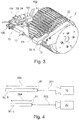
- FIG. 3 shows a device 10 according to another embodiment of the invention, in which a camera 20 in response to a signal of a position sensor 13 in a release position in or against the direction of the end face 51 of the products 50 is movable, the position sensor 13 directed to a measuring position II is.
- the camera 20 is arranged here with an electronic signal processing device 24 in a housing 104.
- the products 50 to be inspected are conveyed in a transverse conveyor 2 designed as a drum.
- the products 50 are held in troughs 103.
- the cross conveyor 2 completes a rotational movement about an axis of rotation at a defined angular velocity.
- the position sensor 13 records the position of the product 50 within the trough 103.
- the product 50 then moves in the direction of rotation in accordance with the rotational movement and passes from the measuring position II to a receiving position III, which is given by the camera 20 and, in this embodiment, a beam deflection 102.
- the beam deflector 102 may be eliminated if the optical axis of the camera 20 is aligned coaxially with the cross conveyor and thus directed towards the product 50.
- the beam deflection 102 includes, for example, prisms and / or mirrors.
- the triggering position of the camera 20 can be determined by the distance between the camera 20 and the product 50 from the position sensor 13 at the measuring position II or the position of the product 50 in the depressions 103 of the transverse conveyor 2.
- the camera 20 is held on a sliding device 100 designed as a linear slide in order to allow an adjustment of the camera 20.
- a motor 101 By means of a motor 101, the position of the camera 20 along the displacement device 100 can be moved parallel to the longitudinal axis of the products 50 in order to be able to adjust the distance between the camera 20 and an end face 51 of the product 50 to be inspected.
- the motor 101 is, for example, an electrically driven motor, preferably a stepping motor and / or a linear motor.
- a suitable sensor and / or preferably by means of the stepping motor the position of the camera 20 can be determined. Based on the known positions of product 50 and camera 20, the triggering position of the camera 20 necessary for a sharp image can be set, for example after a brand and / or format change.
- the displacement device 100 and / or the motor 101 can be dispensed with if, for example, the camera 20 has a variable focal plane which matches the focal plane of the camera 20 or the lens of the camera 20 with the distance between the camera 20 and the end surface 51 allowed.
- an operator of the device 10 performs a rough adjustment adapted to the format and a fine adjustment takes place with the means described in the embodiments.
- the operator can preferably be given feedback on the automatic adjustment.
- FIG. 4 schematically illustrates an arrangement for receiving images of the end faces 51 of products 50 with different lengths 204, 205.
- the different lengths 204, 205 of the products 50 can come about, for example, by a format change.
- the distances 201, 202 between the camera 20 and the end face 51 of the product 50 to be inspected are different.
- a longer product 50 results in a smaller distance 201 while a shorter product 50 results in a larger distance 202.
- the camera 20 may be movable according to the distances 201, 202 in a triggering position and / or have a variable focal plane.
- the variable focal plane can be adjusted so that it is always set according to the distance 201, 202 when taking a picture.
- variable focal plane can be achieved by a zoom lens in order to be able to focus and sharply image the end faces 51 at the given distances 201, 202.
- various distances 201, 202 come about not only by a format change, but also by an inaccurate positioning of the products 50 in, for example, a transverse conveyor 2, which can be compensated according to the embodiments of the invention.
Landscapes
- Health & Medical Sciences (AREA)
- General Health & Medical Sciences (AREA)
- Toxicology (AREA)
- Length Measuring Devices By Optical Means (AREA)
Priority Applications (1)
| Application Number | Priority Date | Filing Date | Title |
|---|---|---|---|
| PL19165376T PL3552501T3 (pl) | 2018-04-09 | 2019-03-27 | Urządzenie i sposób do kontroli czołowej powierzchni sztabkowego wyrobu do palenia |
Applications Claiming Priority (1)
| Application Number | Priority Date | Filing Date | Title |
|---|---|---|---|
| DE102018108288.6A DE102018108288A1 (de) | 2018-04-09 | 2018-04-09 | Vorrichtung und Verfahren zur Inspektion einer Stirnfläche eines stabförmigen Rauchartikels |
Publications (3)
| Publication Number | Publication Date |
|---|---|
| EP3552501A1 true EP3552501A1 (fr) | 2019-10-16 |
| EP3552501B1 EP3552501B1 (fr) | 2021-04-28 |
| EP3552501B2 EP3552501B2 (fr) | 2026-04-08 |
Family
ID=65995492
Family Applications (1)
| Application Number | Title | Priority Date | Filing Date |
|---|---|---|---|
| EP19165376.5A Active EP3552501B2 (fr) | 2018-04-09 | 2019-03-27 | Dispositif et procédé d'inspection d'une surface frontale d'un article à fumer en forme de tige |
Country Status (4)
| Country | Link |
|---|---|
| EP (1) | EP3552501B2 (fr) |
| CN (1) | CN110353302B (fr) |
| DE (1) | DE102018108288A1 (fr) |
| PL (1) | PL3552501T3 (fr) |
Families Citing this family (2)
| Publication number | Priority date | Publication date | Assignee | Title |
|---|---|---|---|---|
| PL438470A1 (pl) * | 2021-07-14 | 2023-01-16 | International Tobacco Machinery Poland Spółka Z Ograniczoną Odpowiedzialnością | Urządzenie do wytwarzania i sposób wytwarzania wielosegmentowych artykułów prętopodobnych |
| KR20240090905A (ko) * | 2021-11-25 | 2024-06-21 | 니뽄 다바코 산교 가부시키가이샤 | 필터의 검사 장치 및 검사 방법 |
Citations (6)
| Publication number | Priority date | Publication date | Assignee | Title |
|---|---|---|---|---|
| US3039606A (en) * | 1960-01-01 | 1962-06-19 | Dearsley George | Cigarette catcher |
| EP1397966A1 (fr) * | 2002-09-11 | 2004-03-17 | Hauni Maschinenbau AG | Appareil et méthode pour transporter des éléments de filtre en forme de tige |
| DE102011006449A1 (de) * | 2011-03-30 | 2012-10-04 | Hauni Maschinenbau Ag | Verfahren und Vorrichtung zum Messen einer physikalischen Eigenschaft eines längsaxial geförderten stabförmigen Artikels der Tabak verarbeitenden Industrie |
| US20130002853A1 (en) * | 2010-03-24 | 2013-01-03 | Okuyama Tetsuya | Filter inspection method and apparatus |
| EP2837294A1 (fr) * | 2013-05-27 | 2015-02-18 | HAUNI Maschinenbau AG | Procédé et dispositif de détermination et/ou d'évaluation de la répartition d'un additif dans un article en forme de tige de l'industrie de traitement du tabac |
| US20150374028A1 (en) * | 2013-02-13 | 2015-12-31 | Philip Morris Products S.A. | Evaluating porosity distribution within a porous rod |
Family Cites Families (11)
| Publication number | Priority date | Publication date | Assignee | Title |
|---|---|---|---|---|
| US5588068A (en) † | 1992-12-04 | 1996-12-24 | Philip Morris Incorporated | Methods and apparatus for inspecting the appearance of substantially circular objects |
| DE19753333A1 (de) * | 1997-12-02 | 1999-06-10 | Focke & Co | Verfahren zur Kontrolle der Vollzähligkeit von Zigarettengruppen und der Befüllung der Zigaretten |
| DE50207393D1 (de) † | 2002-09-11 | 2006-08-10 | Hauni Maschinenbau Ag | Verfahren und Vorrichtung zum Messen der Länge und des Durchmessers von Filterstäben |
| US20100059074A1 (en) † | 2008-09-05 | 2010-03-11 | R. J. Reynolds Tobacco Company | Inspection System for a Smoking Article Having an Object Inserted Therein, and Associated Method |
| WO2012080686A1 (fr) † | 2010-12-15 | 2012-06-21 | Molins Plc | Appareil de formation d'image de caractéristiques d'une tige |
| DE102012210037A1 (de) | 2012-06-14 | 2013-12-19 | Hauni Maschinenbau Ag | Messvorrichtung und Verfahren zur optischen Prüfung einer Stirnfläche eines queraxial geförderten stabförmigen Produkts der Tabak verarbeitenden Industrie |
| DE102013209621A1 (de) † | 2013-05-23 | 2014-11-27 | Hauni Maschinenbau Ag | Messsystem zur optischen Beurteilung eines stabförmigen Artikels der Tabak verarbeitenden Industrie |
| DE102013209831A1 (de) † | 2013-05-27 | 2014-11-27 | Hauni Maschinenbau Ag | Strangmaschine der Tabak verarbeitenden Industrie, und Verfahren zum Steuern einer Strangmaschine |
| DE102015000046A1 (de) † | 2015-01-09 | 2016-07-14 | Hauni Maschinenbau Ag | Vorrichtung und Verfahren zur stirnseitigen lnspektion eines queraxial geförderten stabförmigen Artikels in einer Maschine der Tabak verarbeitenden Industrie |
| PL3394562T3 (pl) † | 2015-12-21 | 2020-06-29 | Philip Morris Products S.A. | Urządzenie i sposób pozyskiwania danych dotyczących wymiaru wydłużonego przedmiotu |
| IT201800010374A1 (it) † | 2018-11-15 | 2020-05-15 | Xepics Sa | Metodo e sistema automatico di misura per la misurazione di parametri fisici e dimensionali di articoli combinati. |
-
2018
- 2018-04-09 DE DE102018108288.6A patent/DE102018108288A1/de active Pending
-
2019
- 2019-03-27 PL PL19165376T patent/PL3552501T3/pl unknown
- 2019-03-27 EP EP19165376.5A patent/EP3552501B2/fr active Active
- 2019-04-08 CN CN201910276064.7A patent/CN110353302B/zh active Active
Patent Citations (6)
| Publication number | Priority date | Publication date | Assignee | Title |
|---|---|---|---|---|
| US3039606A (en) * | 1960-01-01 | 1962-06-19 | Dearsley George | Cigarette catcher |
| EP1397966A1 (fr) * | 2002-09-11 | 2004-03-17 | Hauni Maschinenbau AG | Appareil et méthode pour transporter des éléments de filtre en forme de tige |
| US20130002853A1 (en) * | 2010-03-24 | 2013-01-03 | Okuyama Tetsuya | Filter inspection method and apparatus |
| DE102011006449A1 (de) * | 2011-03-30 | 2012-10-04 | Hauni Maschinenbau Ag | Verfahren und Vorrichtung zum Messen einer physikalischen Eigenschaft eines längsaxial geförderten stabförmigen Artikels der Tabak verarbeitenden Industrie |
| US20150374028A1 (en) * | 2013-02-13 | 2015-12-31 | Philip Morris Products S.A. | Evaluating porosity distribution within a porous rod |
| EP2837294A1 (fr) * | 2013-05-27 | 2015-02-18 | HAUNI Maschinenbau AG | Procédé et dispositif de détermination et/ou d'évaluation de la répartition d'un additif dans un article en forme de tige de l'industrie de traitement du tabac |
Also Published As
| Publication number | Publication date |
|---|---|
| DE102018108288A1 (de) | 2019-10-10 |
| EP3552501B1 (fr) | 2021-04-28 |
| PL3552501T3 (pl) | 2021-11-02 |
| CN110353302B (zh) | 2022-09-09 |
| CN110353302A (zh) | 2019-10-22 |
| EP3552501B2 (fr) | 2026-04-08 |
Similar Documents
| Publication | Publication Date | Title |
|---|---|---|
| EP2677273B1 (fr) | Dispositif de mesure et procédé de contrôle optique d'une surface frontale d'un produit en forme de tige de l'industrie de traitement du tabac acheminé dans le sens transversal-axial | |
| EP1397961B1 (fr) | Procédé et installation pour la mesure de la longueur et du diamètre de tiges de filtre | |
| EP3176588B1 (fr) | Détermination d'une vitesse de balayage d'un dispositif de fabrication additive | |
| EP2918180B1 (fr) | Contrôle optique d'articles en forme de tige de l'industrie de traitement du tabac | |
| EP2769632B2 (fr) | Procédé de mesure et dispositif de mesure pour l'enregistrement de la position d'un objet dans une tige de filtre transportée en direction axiale longitudinale et machine de l'industrie de traitement du tabac | |
| EP2187752A1 (fr) | Dispositif de mesure de graisses de couverture | |
| WO2012130401A1 (fr) | Mise en service d'une machine de l'industrie de transformation du tabac | |
| DE102012201922B3 (de) | Fördereinrichtung zum Fördern stabförmiger Produkte der Tabak verarbeitenden Industrie und Verfahren zur Steuerung einer derartigen Fördervorrichtung | |
| WO2018033430A1 (fr) | Dispositif de mesure et procédé permettant de détecter des éléments électroconducteurs dans des produits ainsi que machine de fabrication de produits de l'industrie du traitement du tabac | |
| EP3552501B1 (fr) | Dispositif et procédé d'inspection d'une surface frontale d'un article à fumer en forme de tige | |
| EP2022347A1 (fr) | Contrôle optique de produits de l'industrie du traitement du tabac | |
| DE3541142C2 (de) | Kontroll- und Korrekturvorrichtung der Querabmessungen von stabförmigen Produkten, insbesondere für Konfektioniermaschinen für Rauchwaren | |
| EP1826557B1 (fr) | Contrôle optique de produits de l'industrie du traitement du tabac | |
| EP0528197B1 (fr) | Procédé et dispositif pour l'inspection de tablettes | |
| EP1479303B1 (fr) | Appareil pour mesurer le diamètre d'un article en forme de tige, notamment de l'industrie du tabac | |
| DE102009058040A1 (de) | Maschine und Verfahren zum Herstellen von Filterstäben für die Tabak verarbeitende Industrie | |
| DE69715350T2 (de) | Verfahren und Vorrichtung zur berührungslosen Prüfung des Endes von Zigaretten oder dergleichen | |
| EP4106557B1 (fr) | Procédé et dispositif d'examen de produits en forme de tige de l'industrie des cigarettes | |
| DE102014209000A1 (de) | Optische Prüfung von stabförmigen Artikeln der Tabak verarbeitenden Industrie | |
| EP3510877B1 (fr) | Dispositif et procédé de vérification des articles en forme de boudin de l'industrie de traitement du tabac | |
| DE102017129737A1 (de) | Vorrichtung zur berührungslosen, optischen 3D-Erfassung einer Stirnfläche eines sich queraxial bewegenden, stabförmigen Artikels der tabakverarbeitenden Industrie | |
| EP1647800A1 (fr) | Méthode et dispositif pour la mesure du diamètre d'un article en forme de tige notamment de l'industrie du tabac | |
| WO2017182362A1 (fr) | Dispositif et procédé de contrôle par voie optique d'articles en forme de tige de l'industrie de traitement du tabac | |
| DE10203095A1 (de) | Verfahren und Vorrichtung zum Messen des Durchmessers von Zigarettenstrang- oder stabförmigen Erzeugnissen der Tabak verarbeitenden Industrie | |
| DE4108166A1 (de) | Verfahren und vorrichtung zum perforieren von zigaretten |
Legal Events
| Date | Code | Title | Description |
|---|---|---|---|
| PUAI | Public reference made under article 153(3) epc to a published international application that has entered the european phase |
Free format text: ORIGINAL CODE: 0009012 |
|
| STAA | Information on the status of an ep patent application or granted ep patent |
Free format text: STATUS: THE APPLICATION HAS BEEN PUBLISHED |
|
| AK | Designated contracting states |
Kind code of ref document: A1 Designated state(s): AL AT BE BG CH CY CZ DE DK EE ES FI FR GB GR HR HU IE IS IT LI LT LU LV MC MK MT NL NO PL PT RO RS SE SI SK SM TR |
|
| AX | Request for extension of the european patent |
Extension state: BA ME |
|
| RIN1 | Information on inventor provided before grant (corrected) |
Inventor name: EL JARAD, AKRAM Inventor name: GAST, HANNO |
|
| STAA | Information on the status of an ep patent application or granted ep patent |
Free format text: STATUS: REQUEST FOR EXAMINATION WAS MADE |
|
| 17P | Request for examination filed |
Effective date: 20200409 |
|
| RBV | Designated contracting states (corrected) |
Designated state(s): AL AT BE BG CH CY CZ DE DK EE ES FI FR GB GR HR HU IE IS IT LI LT LU LV MC MK MT NL NO PL PT RO RS SE SI SK SM TR |
|
| GRAP | Despatch of communication of intention to grant a patent |
Free format text: ORIGINAL CODE: EPIDOSNIGR1 |
|
| STAA | Information on the status of an ep patent application or granted ep patent |
Free format text: STATUS: GRANT OF PATENT IS INTENDED |
|
| INTG | Intention to grant announced |
Effective date: 20201102 |
|
| GRAS | Grant fee paid |
Free format text: ORIGINAL CODE: EPIDOSNIGR3 |
|
| GRAA | (expected) grant |
Free format text: ORIGINAL CODE: 0009210 |
|
| STAA | Information on the status of an ep patent application or granted ep patent |
Free format text: STATUS: THE PATENT HAS BEEN GRANTED |
|
| AK | Designated contracting states |
Kind code of ref document: B1 Designated state(s): AL AT BE BG CH CY CZ DE DK EE ES FI FR GB GR HR HU IE IS IT LI LT LU LV MC MK MT NL NO PL PT RO RS SE SI SK SM TR |
|
| REG | Reference to a national code |
Ref country code: GB Ref legal event code: FG4D Free format text: NOT ENGLISH |
|
| REG | Reference to a national code |
Ref country code: CH Ref legal event code: EP |
|
| REG | Reference to a national code |
Ref country code: AT Ref legal event code: REF Ref document number: 1386093 Country of ref document: AT Kind code of ref document: T Effective date: 20210515 |
|
| REG | Reference to a national code |
Ref country code: DE Ref legal event code: R096 Ref document number: 502019001294 Country of ref document: DE |
|
| REG | Reference to a national code |
Ref country code: IE Ref legal event code: FG4D Free format text: LANGUAGE OF EP DOCUMENT: GERMAN |
|
| REG | Reference to a national code |
Ref country code: NL Ref legal event code: FP |
|
| REG | Reference to a national code |
Ref country code: LT Ref legal event code: MG9D |
|
| PG25 | Lapsed in a contracting state [announced via postgrant information from national office to epo] |
Ref country code: FI Free format text: LAPSE BECAUSE OF FAILURE TO SUBMIT A TRANSLATION OF THE DESCRIPTION OR TO PAY THE FEE WITHIN THE PRESCRIBED TIME-LIMIT Effective date: 20210428 Ref country code: HR Free format text: LAPSE BECAUSE OF FAILURE TO SUBMIT A TRANSLATION OF THE DESCRIPTION OR TO PAY THE FEE WITHIN THE PRESCRIBED TIME-LIMIT Effective date: 20210428 Ref country code: LT Free format text: LAPSE BECAUSE OF FAILURE TO SUBMIT A TRANSLATION OF THE DESCRIPTION OR TO PAY THE FEE WITHIN THE PRESCRIBED TIME-LIMIT Effective date: 20210428 Ref country code: BG Free format text: LAPSE BECAUSE OF FAILURE TO SUBMIT A TRANSLATION OF THE DESCRIPTION OR TO PAY THE FEE WITHIN THE PRESCRIBED TIME-LIMIT Effective date: 20210728 |
|
| PG25 | Lapsed in a contracting state [announced via postgrant information from national office to epo] |
Ref country code: GR Free format text: LAPSE BECAUSE OF FAILURE TO SUBMIT A TRANSLATION OF THE DESCRIPTION OR TO PAY THE FEE WITHIN THE PRESCRIBED TIME-LIMIT Effective date: 20210729 Ref country code: IS Free format text: LAPSE BECAUSE OF FAILURE TO SUBMIT A TRANSLATION OF THE DESCRIPTION OR TO PAY THE FEE WITHIN THE PRESCRIBED TIME-LIMIT Effective date: 20210828 Ref country code: LV Free format text: LAPSE BECAUSE OF FAILURE TO SUBMIT A TRANSLATION OF THE DESCRIPTION OR TO PAY THE FEE WITHIN THE PRESCRIBED TIME-LIMIT Effective date: 20210428 Ref country code: NO Free format text: LAPSE BECAUSE OF FAILURE TO SUBMIT A TRANSLATION OF THE DESCRIPTION OR TO PAY THE FEE WITHIN THE PRESCRIBED TIME-LIMIT Effective date: 20210728 Ref country code: PT Free format text: LAPSE BECAUSE OF FAILURE TO SUBMIT A TRANSLATION OF THE DESCRIPTION OR TO PAY THE FEE WITHIN THE PRESCRIBED TIME-LIMIT Effective date: 20210830 Ref country code: RS Free format text: LAPSE BECAUSE OF FAILURE TO SUBMIT A TRANSLATION OF THE DESCRIPTION OR TO PAY THE FEE WITHIN THE PRESCRIBED TIME-LIMIT Effective date: 20210428 Ref country code: SE Free format text: LAPSE BECAUSE OF FAILURE TO SUBMIT A TRANSLATION OF THE DESCRIPTION OR TO PAY THE FEE WITHIN THE PRESCRIBED TIME-LIMIT Effective date: 20210428 |
|
| REG | Reference to a national code |
Ref country code: DE Ref legal event code: R026 Ref document number: 502019001294 Country of ref document: DE |
|
| PLBI | Opposition filed |
Free format text: ORIGINAL CODE: 0009260 |
|
| PG25 | Lapsed in a contracting state [announced via postgrant information from national office to epo] |
Ref country code: ES Free format text: LAPSE BECAUSE OF FAILURE TO SUBMIT A TRANSLATION OF THE DESCRIPTION OR TO PAY THE FEE WITHIN THE PRESCRIBED TIME-LIMIT Effective date: 20210428 Ref country code: EE Free format text: LAPSE BECAUSE OF FAILURE TO SUBMIT A TRANSLATION OF THE DESCRIPTION OR TO PAY THE FEE WITHIN THE PRESCRIBED TIME-LIMIT Effective date: 20210428 Ref country code: SK Free format text: LAPSE BECAUSE OF FAILURE TO SUBMIT A TRANSLATION OF THE DESCRIPTION OR TO PAY THE FEE WITHIN THE PRESCRIBED TIME-LIMIT Effective date: 20210428 Ref country code: SM Free format text: LAPSE BECAUSE OF FAILURE TO SUBMIT A TRANSLATION OF THE DESCRIPTION OR TO PAY THE FEE WITHIN THE PRESCRIBED TIME-LIMIT Effective date: 20210428 Ref country code: RO Free format text: LAPSE BECAUSE OF FAILURE TO SUBMIT A TRANSLATION OF THE DESCRIPTION OR TO PAY THE FEE WITHIN THE PRESCRIBED TIME-LIMIT Effective date: 20210428 Ref country code: DK Free format text: LAPSE BECAUSE OF FAILURE TO SUBMIT A TRANSLATION OF THE DESCRIPTION OR TO PAY THE FEE WITHIN THE PRESCRIBED TIME-LIMIT Effective date: 20210428 Ref country code: CZ Free format text: LAPSE BECAUSE OF FAILURE TO SUBMIT A TRANSLATION OF THE DESCRIPTION OR TO PAY THE FEE WITHIN THE PRESCRIBED TIME-LIMIT Effective date: 20210428 |
|
| PLAX | Notice of opposition and request to file observation + time limit sent |
Free format text: ORIGINAL CODE: EPIDOSNOBS2 |
|
| 26 | Opposition filed |
Opponent name: G.D S.P.A. Effective date: 20220127 |
|
| PG25 | Lapsed in a contracting state [announced via postgrant information from national office to epo] |
Ref country code: IS Free format text: LAPSE BECAUSE OF FAILURE TO SUBMIT A TRANSLATION OF THE DESCRIPTION OR TO PAY THE FEE WITHIN THE PRESCRIBED TIME-LIMIT Effective date: 20210828 Ref country code: AL Free format text: LAPSE BECAUSE OF FAILURE TO SUBMIT A TRANSLATION OF THE DESCRIPTION OR TO PAY THE FEE WITHIN THE PRESCRIBED TIME-LIMIT Effective date: 20210428 |
|
| PLBB | Reply of patent proprietor to notice(s) of opposition received |
Free format text: ORIGINAL CODE: EPIDOSNOBS3 |
|
| REG | Reference to a national code |
Ref country code: DE Ref legal event code: R081 Ref document number: 502019001294 Country of ref document: DE Owner name: KOERBER TECHNOLOGIES GMBH, DE Free format text: FORMER OWNER: HAUNI MASCHINENBAU GMBH, 21033 HAMBURG, DE |
|
| PG25 | Lapsed in a contracting state [announced via postgrant information from national office to epo] |
Ref country code: MC Free format text: LAPSE BECAUSE OF FAILURE TO SUBMIT A TRANSLATION OF THE DESCRIPTION OR TO PAY THE FEE WITHIN THE PRESCRIBED TIME-LIMIT Effective date: 20210428 |
|
| REG | Reference to a national code |
Ref country code: CH Ref legal event code: PL |
|
| REG | Reference to a national code |
Ref country code: NL Ref legal event code: HC Owner name: KOERBER TECHNOLOGIES GMBH; DE Free format text: DETAILS ASSIGNMENT: CHANGE OF OWNER(S), CHANGE OF OWNER(S) NAME; FORMER OWNER NAME: HAUNI MASCHINENBAU GMBH Effective date: 20221031 |
|
| REG | Reference to a national code |
Ref country code: BE Ref legal event code: MM Effective date: 20220331 |
|
| RAP4 | Party data changed (patent owner data changed or rights of a patent transferred) |
Owner name: KOERBER TECHNOLOGIES GMBH |
|
| PG25 | Lapsed in a contracting state [announced via postgrant information from national office to epo] |
Ref country code: LU Free format text: LAPSE BECAUSE OF NON-PAYMENT OF DUE FEES Effective date: 20220327 Ref country code: LI Free format text: LAPSE BECAUSE OF NON-PAYMENT OF DUE FEES Effective date: 20220331 Ref country code: IE Free format text: LAPSE BECAUSE OF NON-PAYMENT OF DUE FEES Effective date: 20220327 Ref country code: FR Free format text: LAPSE BECAUSE OF NON-PAYMENT OF DUE FEES Effective date: 20220331 Ref country code: CH Free format text: LAPSE BECAUSE OF NON-PAYMENT OF DUE FEES Effective date: 20220331 |
|
| PG25 | Lapsed in a contracting state [announced via postgrant information from national office to epo] |
Ref country code: BE Free format text: LAPSE BECAUSE OF NON-PAYMENT OF DUE FEES Effective date: 20220331 |
|
| APAH | Appeal reference modified |
Free format text: ORIGINAL CODE: EPIDOSCREFNO |
|
| APBM | Appeal reference recorded |
Free format text: ORIGINAL CODE: EPIDOSNREFNO |
|
| APBP | Date of receipt of notice of appeal recorded |
Free format text: ORIGINAL CODE: EPIDOSNNOA2O |
|
| P01 | Opt-out of the competence of the unified patent court (upc) registered |
Effective date: 20230616 |
|
| APBQ | Date of receipt of statement of grounds of appeal recorded |
Free format text: ORIGINAL CODE: EPIDOSNNOA3O |
|
| GBPC | Gb: european patent ceased through non-payment of renewal fee |
Effective date: 20230327 |
|
| PG25 | Lapsed in a contracting state [announced via postgrant information from national office to epo] |
Ref country code: GB Free format text: LAPSE BECAUSE OF NON-PAYMENT OF DUE FEES Effective date: 20230327 |
|
| PG25 | Lapsed in a contracting state [announced via postgrant information from national office to epo] |
Ref country code: GB Free format text: LAPSE BECAUSE OF NON-PAYMENT OF DUE FEES Effective date: 20230327 |
|
| PG25 | Lapsed in a contracting state [announced via postgrant information from national office to epo] |
Ref country code: MK Free format text: LAPSE BECAUSE OF FAILURE TO SUBMIT A TRANSLATION OF THE DESCRIPTION OR TO PAY THE FEE WITHIN THE PRESCRIBED TIME-LIMIT Effective date: 20210428 Ref country code: CY Free format text: LAPSE BECAUSE OF FAILURE TO SUBMIT A TRANSLATION OF THE DESCRIPTION OR TO PAY THE FEE WITHIN THE PRESCRIBED TIME-LIMIT Effective date: 20210428 |
|
| PG25 | Lapsed in a contracting state [announced via postgrant information from national office to epo] |
Ref country code: HU Free format text: LAPSE BECAUSE OF FAILURE TO SUBMIT A TRANSLATION OF THE DESCRIPTION OR TO PAY THE FEE WITHIN THE PRESCRIBED TIME-LIMIT; INVALID AB INITIO Effective date: 20190327 |
|
| APAH | Appeal reference modified |
Free format text: ORIGINAL CODE: EPIDOSCREFNO |
|
| PG25 | Lapsed in a contracting state [announced via postgrant information from national office to epo] |
Ref country code: TR Free format text: LAPSE BECAUSE OF FAILURE TO SUBMIT A TRANSLATION OF THE DESCRIPTION OR TO PAY THE FEE WITHIN THE PRESCRIBED TIME-LIMIT Effective date: 20210428 |
|
| PG25 | Lapsed in a contracting state [announced via postgrant information from national office to epo] |
Ref country code: MT Free format text: LAPSE BECAUSE OF FAILURE TO SUBMIT A TRANSLATION OF THE DESCRIPTION OR TO PAY THE FEE WITHIN THE PRESCRIBED TIME-LIMIT Effective date: 20210428 |
|
| PGFP | Annual fee paid to national office [announced via postgrant information from national office to epo] |
Ref country code: DE Payment date: 20250331 Year of fee payment: 7 |
|
| REG | Reference to a national code |
Ref country code: AT Ref legal event code: MM01 Ref document number: 1386093 Country of ref document: AT Kind code of ref document: T Effective date: 20240327 |
|
| PGFP | Annual fee paid to national office [announced via postgrant information from national office to epo] |
Ref country code: IT Payment date: 20250327 Year of fee payment: 7 |
|
| PG25 | Lapsed in a contracting state [announced via postgrant information from national office to epo] |
Ref country code: AT Free format text: LAPSE BECAUSE OF NON-PAYMENT OF DUE FEES Effective date: 20240327 |
|
| APBU | Appeal procedure closed |
Free format text: ORIGINAL CODE: EPIDOSNNOA9O |
|
| PUAH | Patent maintained in amended form |
Free format text: ORIGINAL CODE: 0009272 |
|
| STAA | Information on the status of an ep patent application or granted ep patent |
Free format text: STATUS: PATENT MAINTAINED AS AMENDED |
|
| REG | Reference to a national code |
Ref country code: CH Ref legal event code: M12 Free format text: ST27 STATUS EVENT CODE: U-0-0-M10-M12 (AS PROVIDED BY THE NATIONAL OFFICE) Effective date: 20260311 |
|
| 27A | Patent maintained in amended form |
Effective date: 20260408 |
|
| AK | Designated contracting states |
Kind code of ref document: B2 Designated state(s): AL AT BE BG CH CY CZ DE DK EE ES FI FR GB GR HR HU IE IS IT LI LT LU LV MC MK MT NL NO PL PT RO RS SE SI SK SM TR |
|
| REG | Reference to a national code |
Ref country code: DE Ref legal event code: R102 Ref document number: 502019001294 Country of ref document: DE |
|
| PGFP | Annual fee paid to national office [announced via postgrant information from national office to epo] |
Ref country code: AT Payment date: 20260410 Year of fee payment: 5 |
|
| PGFP | Annual fee paid to national office [announced via postgrant information from national office to epo] |
Ref country code: NL Payment date: 20260330 Year of fee payment: 8 |
|
| PGFP | Annual fee paid to national office [announced via postgrant information from national office to epo] |
Ref country code: PL Payment date: 20260220 Year of fee payment: 8 |