EP3552561B1 - Pince de ligature présentant des caractéristiques de verrouillage et de rétention - Google Patents
Pince de ligature présentant des caractéristiques de verrouillage et de rétention Download PDFInfo
- Publication number
- EP3552561B1 EP3552561B1 EP19168518.9A EP19168518A EP3552561B1 EP 3552561 B1 EP3552561 B1 EP 3552561B1 EP 19168518 A EP19168518 A EP 19168518A EP 3552561 B1 EP3552561 B1 EP 3552561B1
- Authority
- EP
- European Patent Office
- Prior art keywords
- side wall
- ligation clip
- protrusions
- jaw
- clamping surface
- Prior art date
- Legal status (The legal status is an assumption and is not a legal conclusion. Google has not performed a legal analysis and makes no representation as to the accuracy of the status listed.)
- Active
Links
Images


Classifications
-
- A—HUMAN NECESSITIES
- A61—MEDICAL OR VETERINARY SCIENCE; HYGIENE
- A61B—DIAGNOSIS; SURGERY; IDENTIFICATION
- A61B17/00—Surgical instruments, devices or methods
- A61B17/12—Surgical instruments, devices or methods for ligaturing or otherwise compressing tubular parts of the body, e.g. blood vessels or umbilical cord
- A61B17/122—Clamps or clips, e.g. for the umbilical cord
Definitions
- the present disclosure is directed to ligation clips for sealing body vessels and, more particularly, to polymeric ligation clips that include latching structure and tissue retention features for securely clamping the ligation clip about a body vessel.
- Ligation clips are well known in the surgical arts and are commonly used during a variety of surgical procedures to ligate tissue, e.g., a body vessel.
- ligation clips include first and second jaws that include clamping surfaces. The jaws are pivotably connected to each other and movable between open and clamped positions. When the ligation clip is clamped about tissue, the tissue is compressed between the clamping surfaces of the first and second jaws.
- the jaws of the ligation clip include a latching mechanism to retain the ligation clip in the clamped position about tissue and retention structure positioned on the clamping surfaces of the jaws to prevent the clamped ligation clip from moving in relation to the tissue. Any movement of the clamped ligation clip in relation to the tissue may have a negative impact on the performance of the ligation clip.
- Ligation clips can be formed of polymeric materials. In current polymeric clip designs, pre-compressing the ligation clip or closing the ligation clip may deform latching mechanism such that the reliability of the latching mechanism is impaired. The loss of the ability to maintain the ligation clip in the clamped position about a body vessel may result in movement of the ligation clip in relation to the body vessel or disengagement of the ligation clip from the body vessel.
- US 9282972 B1 describes ligation clips according to the preamble of claim 1.
- the ligation clips have clamping surfaces that may include non-slip protrusions such as ribs, ridges, cones or pins.
- US 2668538 A describes surgical forceps having rows of teeth on the clamping jaws of the forceps.
- WO 2016/205343 A1 describes an anti-migration surgical ligation clip.
- Each jaw of the ligation clip has a plurality of protrusions configured for gripping tissue.
- US 9220507 B1 describes a tissue-spreading vascular clip with a locking mechanism and non-slip clamping surfaces.
- the clamping side of one jaw may include a wedge-shaped elongated ridge, wherein the clamping side of the other jaw includes a corresponding trough.
- the clamping surfaces may include non-slip protrusions.
- US 5423831 A describes an umbilical cord clamp having a row of teeth on each clamping jaw and a locking mechanism.
- the present invention provides a ligation clip as defined in claim 1.
- Preferred embodiments of the invention are defined in the dependent claims.
- the protrusions in the first row of protrusions are longitudinally aligned and spaced from each other and the protrusions in the second row of protrusions are longitudinally aligned and spaced from each other.
- each of the protrusions in the first row of protrusions is longitudinally offset from the each of protrusions in the second row of protrusions such that the protrusions are alternatingly positioned on opposite sides of the second clamping surface along the length of the second clamping surface.
- the first jaw includes a first locking element and the second jaw includes a second locking element, wherein the first locking element is movable into engagement with the second locking element to retain the ligation clip in the clamped position.
- the first or second locking element includes a head including a first side wall defining a first notch
- the other of the first or second locking element includes a box-like structure defining a through bore having a first locking tab extending into the through bore, wherein the first locking tab is positioned to be received within the first notch of the head to retain the ligation clip in the clamped position.
- the head includes a second side wall defining a second notch and the box-like structure includes a second locking tab that extends into the through bore, wherein the second locking tab is positioned to be received within the second notch of the head to retain the ligation clip in the clamped position.
- the first notch and the first locking tab have triangular configurations.
- the box-like structure is rectangular in shape and is defined by angled side walls and a radiused proximal wall that are configured to guide the head into the through bore of the box-like structure.
- the head has a rectangular cross-sectional shape and the through bore is configured to receive the head.
- the box-like structure has an open distal end.
- the first or second locking element includes a head supporting a stop member that extends outwardly of the head, and the other of the first or second locking element includes a box-like structure that defines a through bore.
- the stop member is deformable to facilitate passage of the stop member through the through bore during movement of the ligation clip from the open position to the closed position.
- the stop member is configured in an undeformed state to engage the box-like structure to obstruct movement of the ligation clip from the clamped position to the open position.
- the head includes a hooked portion and the other one of the first and second locking elements includes an engagement portion, wherein the hooked portion is positioned to engage the engagement portion to retain the ligation clip in the clamped position.
- proximal is used generally to refer to that portion of the device that is closer to a clinician
- distal is used generally to refer to that portion of the device that is farther from the clinician
- clinician is used generally to refer to medical personnel including doctors, nurses, and support personnel.
- the ligation clip 10 defines a longitudinal axis "Z" ( FIG. 3 ) and includes a first jaw 12, a second jaw 14, and a hinge portion 16 coupling the first jaw 12 to the second jaw14.
- the first jaw 12 is pivotable in relation to the second jaw 14 about the hinge portion 16 to move the ligation clip 10 between an open position ( FIG. 1 ) and a clamped position ( FIG. 3 ).
- the first and second jaws 12, 14 are curved along the longitudinal axis "Z" ( FIG. 3 ) although other jaw configurations are envisioned.
- the hinge portion 16 may be integrally formed with the first and second jaws 12, 14, e.g., a living hinge, and may define a crescent shaped through bore 16a to facilitate movement of the first jaw 12 in relation to the second jaw 14 between the open and clamped positions.
- the through bore 16a also allows for substantially complete closure of the proximal portions of the first and second jaws 12, 14.
- the first jaw 12 includes a proximal portion 18, a distal portion 20, and a clamping surface 22.
- the second jaw 14 includes a proximal portion 24, a distal portion 26, and a clamping surface 28.
- the proximal portions 18, 24 of the first and second jaws 12, 14, respectively, are coupled to the hinge portion 16.
- the distal portion 20 of first jaw 12 includes a first locking element 30 and spaced bosses 33.
- the first locking element 30 forms a first part of a latching mechanism 29 ( FIG. 3 ) of the ligation clip 10 and includes a head 32 that extends downwardly from the tissue clamping surface 22.
- the head 32 includes a distal end defined by tapered surfaces 34 and a sidewall having a notch 36 spaced proximally of the tapered surfaces 34.
- the notch 36 may be triangular in shape.
- the head 32 may have a rectangular cross-sectional shape. Alternately, other configurations are envisioned.
- the latching mechanism 29 ( FIG.
- the bosses 33 define ends of a cylindrical member supported on the first jaw 12.
- the bosses 33 are positioned and configured to engage the jaws of an applicator (not shown) to facilitate placement of the ligation clip 10 on tissue and are not described in further detail herein.
- the distal portion 26 of the second jaw 14 includes a second locking element 40 and spaced bosses 42.
- the second locking element 40 forms a second part of the latching mechanism 29 ( FIG. 3 .)
- the second locking element 40 includes a box-like structure 46 that defines a through bore 46a and includes a locking tab 48 that extends into the through bore 46a of the box-like structure 46.
- the through bore 46a is dimensioned to receive the head 32 of the first locking element 30 when the ligation clip 10 is moved from the open position ( FIG. 1 ) to the clamped position ( FIG. 3A ).
- the locking tab 48 is received within the notch 36 in the side wall of the first locking element 30 of the first jaw 12 to secure the ligation clip 10 in the clamped position.
- the through bore 46a defined by the box-like structure 46 of the second locking element 40 is rectangular in shape and is defined by angled walls side walls 49 and radiused proximal and distal walls 49a ( FIG. 1A ).
- the side walls 49 and the proximal and distal walls are configured to guide the head 32 of the first locking element 30 into the through bore 46a.
- the bosses 42 are similar to the bosses 33 of the first jaw 12 and are configured to engage jaws of an applicator (not shown) to facilitate application of the ligation clip 10 to tissue.
- the first clamping surface 22 is substantially flat and supports a stepped longitudinal rib 60 ( FIG. 3B ) having opposite side walls 60a, 60b.
- Each of the side walls 60a, 60b of the stepped longitudinal rib 60 is defined by a substantially vertical side wall portion 62, an angled side wall portion 64, and vertical side wall portions 66.
- the vertical side wall portions 62 are contiguous with and extend outwardly from the first clamping surface 22 of the first jaw 12.
- the angled side wall portions 64 interconnect the vertical side wall portions 62 to the vertical side wall portions 66.
- the vertical side wall portions 66 are connected by a tissue engaging surface 66a of the longitudinal rib 60 that is in opposition with the clamping surface 28 of the second jaw 14 when the ligation clip 10 is in the clamped position.
- the stepped longitudinal rib 60 is rectangular and has a first width adjacent the clamping surface 22 and a second width adjacent the tissue engaging wall 66a that is smaller than the first width.
- the tissue engaging surface 66a of the longitudinal rib 60 is substantially flat and extends substantially the entire length of the tissue clamping surface 22.
- the longitudinal rib 60 may include one or more longitudinal rib sections that are longitudinally spaced from each other and extend over a length less than the entire length of the tissue clamping surface 22, e.g., 50-80 percent of the length of the tissue clamping surface 22.
- the surface 66a of the stepped longitudinal rib 60 need not be flat but could be curved, ribbed, knurled, or otherwise configured to grip or retain tissue.
- the second clamping surface 28 is substantially flat and supports a first row of protrusions 70a and a second row of protrusions 70b.
- Each of the protrusions 70a of the first row of protrusions 70a is spaced from but longitudinally aligned with each of the other protrusions 70a along a first side of the second clamping surface 28.
- each of the protrusions70b of the second row of protrusions 70b is longitudinally aligned with each of the other protrusions 70b along a second side of the second clamping surface 28.
- the protrusions 70a, 70b may have a width that is less than half the width of the clamping surface 28 to define an unobstructed central channel 71 between the first and second rows of protrusions 70a, 70b on the second clamping surface 28.
- the central channel 71 is dimensioned to receive the stepped longitudinal rib 60 when the ligation clip 10 is in the clamped position.
- each of the protrusions 70a on the first side of the clamping surface 28 are longitudinally offset from the each of protrusions 70b positioned on the other side of the clamping surface 28 such that the protrusions 70a and 70b are alternatingly positioned on opposite sides of the clamping surface 28 along the length of the clamping surface 28.
- each of the protrusions 70a, 70b includes a tissue engaging surface 72 and an inner side wall 73.
- the tissue engaging surface 72 is positioned in opposition to the clamping surface 22 of the first jaw 12 when the ligation clip 10 is in the clamped position.
- the inner side wall 73 of each of the protrusions 70a, 70b is positioned in opposition to the one of the side walls 60a, 60b of the stepped longitudinal rib 60 when the ligation clip 10 is in the clamped position ( FIG. 3B ).
- each of the protrusions 70a, 70b of the first and second rows of protrusions 70a, 70b has a first substantially vertical wall portion 74 that is contiguous with the tissue engaging surface 72 and an angled wall portion 76 that extends from the vertical wall portion 74 towards the clamping surface 28 of the second jaw 14.
- the inner side wall 73 of the protrusions 70a, 70b also include a second substantially vertical wall portion 80 that extends between the angled wall portion 76 and the clamping surface 28.
- the vertical portions 74 of the protrusions 70a, 70b are positioned to align with vertical side wall portions 62 of the stepped longitudinal rib 60 when the ligation clip 10 is in the clamped position and the angled wall portion 76 of the protrusions 70a, 70b are positioned to align with the angled wall portion 64 of the longitudinal rib 60 of the first jaw 12 when the ligation clip 10 is in the clamped position.
- the vertical wall portions 80 of the protrusions 70a, 70b are positioned to align with the side wall portions 66 of the stepped longitudinal rib 60 of the first jaw 12 when the ligation clip 10 is in the clamped position.
- the first jaw 12 and the second jaw 14 are moved from the open position ( FIG. 1 ) to the clamped position ( FIG. 3 ) in the direction indicated by arrow A in FIG. 3 , the first jaw 12 pivots in relation to the second jaw 14 about the hinge 16 to move the head 32 of the first locking element 30 through the through bore 46a of the box-like structure 46 of the second locking element 40 to secure the ligation clip 10 in the clamped position.
- the tapered walls 49 and the radiused walls FIG.
- the stepped longitudinal rib 60 on the clamping surface 22 of the first jaw 12 is received in the central channel 71 defined between the first and second rows of protrusions 70a, 70b on the clamping surface 28 of the second jaw 14.
- the protrusions 70a and 70b are longitudinally offset from each other such that the protrusions 70a, 70b are alternatingly space on opposite sides of the ligation clip 10 along the clamping surfaces 22, 28 of the first and second jaws 12, 14.
- the surgical ligation clip 10 may be made, in whole or in part, of a resilient bioabsorbable and/or biocompatible polymeric material.
- suitable bioabsorbable and/or biocompatible polymers include acetal polyoxymethylene (POM), polyethylene terephthalate (PET), polybutylene terephthalate (PBT), polyoxymethylene, polyetheretherketone (PEEK), polypropylene, and polyethylene or other thermoplastic materials having similar properties that can be injection-molded.
- the clip may also be made of a polymer material or materials in combination with radiolucent metal alloys. Alternately, other materials may be used to form the clip 10 including biocompatible metals, plastics and composites.
- the ligation clip 10 is positioned about tissue "T", e.g., vasculature, such that the tissue "T” is positioned between the tissue clamping surface 22 of the first jaw 12 and the tissue clamping surface 28 of the second jaw 14.
- tissue "T" e.g., vasculature
- the first jaw 12 pivots in relation to the second jaw 14 about the hinge 16 to move the projection 32 of the first locking element 30 into box-like structure 46 of the second locking element 40.
- the locking tab 48 of the second locking element 40 is deformed and subsequently snaps into the notch 36 of the first locking element 30 to secure the ligation clip 10 in the clamped position.
- the notch 36 and the locking tab 48 define right-triangles which are configured to resist unlatching of the ligation clip 10 ( FIG. 3A ).
- the tissue “T” in the clamped position, the tissue “T” is compressed between the first and second clamping surfaces 22, 28 of the first and second jaws 12, 14, respectively. More particularly, when the ligation clip 10 is moved to the clamped position, the tissue “T” is compressed between the tissue engaging surfaces 72 of the protrusions 70a, 70b and the clamping surface 22 of the first jaw 12, between the angled wall portions of the protrusions 70a, 70b and the angled side wall portion 64 of the longitudinal rib 60, and between the tissue engaging surface 66a of the longitudinal rib 60 and the clamping surface 22 of the first jaw 12.
- the above described ligation clip 10 including a first jaw 12 having a stepped longitudinal rib 60 and a second jaw 14 including first and second rows of protrusions 70a, 70b that are in opposition to the longitudinal rib in the clamped position of the ligation clip 10 improve the retention forces of the ligation clip 10 on the tissue "T".
- the latching mechanism 29 including the notched head 32 on the first jaw 12 and the locking tab 48 on the second jaw 14 securely fastens the ligation clip 10 onto tissue "T".
- the combination of the retention structure and latching structure on the first and second jaws 12, 14 minimizes the likelihood that the ligation clip 10 will slide in a direction parallel to the clamping surfaces 22, 28 of the first and second jaws 12, 14, respectively, after the ligation clip 10 has been clamped about the tissue "T".
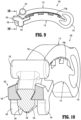
- FIGS. 8-10 illustrate another exemplary embodiment of the presently disclosed ligation clip shown generally as ligation clip 100.
- Ligation clip 100 is similar to ligation clip 10 in most respects and includes a first jaw 112, a second jaw 114 and a hinge portion 116.
- the first jaw 112 includes a clamping surface 122 that supports a longitudinal rib 160.
- the second jaw 114 includes a clamping surface 128 that supports a first row of projections 170a positioned along a first edge of the clamping surface 128 and a second row of projections 170b positioned along an opposite side of the clamping surface 128.
- the first and second rows of projections 170a, 170b define a central channel 171 that is dimensioned to receive the longitudinal rib 160 of the first jaw 12 when the ligation clip 100 is in a clamped position.
- the first and second jaws 112, 114 support bosses 133, 142, respectively.
- the ligation clip 100 differs from the ligation clip 10 ( FIG. 1 ) in that the latching mechanism 129 is modified. More particularly, the first jaw 112 includes a first locking element 130 that includes a head 132 that extends downwardly from the tissue clamping surface 122. In embodiments, the head 132 includes a distal end defined by tapered surfaces 134 and side walls including diametrically opposed notches 136 that are spaced proximally of the tapered surfaces 134. In some embodiments, the notches 136 may be triangular in shape. In certain embodiments, the head 132 may have a rectangular cross-sectional shape. Alternately, other notch and protrusion configurations are envisioned.
- the second jaw 114 includes a second locking element 140 that forms a second part of the latching mechanism 129 ( FIG. 10 .)
- the second locking element 140 includes a box-like structure 146 that defines an open ended through bore or channel 146a and includes two locking tabs 148 that extend into the channel 146a of the box-like structure 146.
- the channel 146a is dimensioned to receive the head 132 of the first locking element 130 when the ligation clip 100 is moved from the open position ( FIG. 8 ) to the clamped position ( FIG. 10 ) such that the locking tabs148 are received within the notches 136 formed in the side walls of the first locking element 130 of the first jaw 112 to secure the ligation clip 100 in the clamped position.
- the channel 146a defined by the box-like structure 146 of the second locking element 40 is rectangular in shape and is defined by side walls 149 and a proximal wall 149a.
- the distal end of the box-like structure 146 is open.
- the side walls 149 and the proximal wall 149a may be configured to guide the head 132 of the first locking element 130 into the through bore 146a.
- the latching mechanism 129 ( FIG. 10 ) is configured to retain the ligation clip 100 in the clamped position as described above in regard to ligation clip 10 ( FIG. 3A ).
- the notches 136 and the locking tabs 148 define right-triangles that resist unlatching of the ligation clip 100.
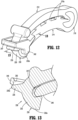
- FIGS. 11-13 illustrate another exemplary embodiment of the presently disclosed ligation clip shown generally as ligation clip 200.
- Ligation clip 200 is similar to ligation clip 10 in most respects and includes a first jaw 212, a second jaw 214 and a hinge portion 216.
- the first jaw 212 includes a clamping surface 222 that supports a longitudinal rib 260.
- the second jaw 214 includes a clamping surface 228 that supports a first row of projections 270a positioned along a first edge of the clamping surface 228 and a second row of projections 270b positioned along an opposite side of the clamping surface 228.
- the first and second rows of projections 270a, 270b define a central channel 271 that is dimensioned to receive the longitudinal rib 260 when the ligation clip 200 is in a clamped position.
- the first and second jaws 212, 214 support bosses 233, 242, respectively.
- the ligation clip 200 differs from the ligation clip 10 ( FIG. 1 ) in that the latching mechanism 239 is modified. More particularly, the first jaw 212 includes a first locking element 230 and the second jaw 214 includes a second locking element 240 that together define the latching mechanism 239.
- the first locking element 230 includes a head 232 including a hooked portion 232a, and a stop member 235.
- the stop member 235 has a radiused distal surface 235a.
- the hooked portion 232 extends downwardly and proximally from the tissue clamping surface 222.
- the second locking element 240 includes a box-like structure 246 that defines a through bore 246a, a cam surface 247, and an engagement portion 248 ( FIG. 13 ).
- the box-like structure 246 includes a distal wall 250.
- the through bore 246a is dimensioned to receive the hooked portion 232 of the first locking element 230 and the stop member 235 when the ligation clip 200 is moved from an open position ( FIG. 11 ) to a clamped position ( FIG. 13 ). As the ligation clip 200 is moved to the clamped position, the head 232 and the stop member 235 move through the through bore 246a.
- the stop member 235 As the stop member 235 engages the distal wall 250 of the box-like structure 246, the stop member 235 flexes and passes under the distal wall 250 of the box-like structure 246. As the stop member 235 passes under the distal wall 250 of the box-like structure 246, the stop member 235 returns to its undeformed state to a position beneath the distal wall 250 to lock the ligation clip 10 in the clamped position. After the head 232 passes through the box-like structure 246, the hooked portion 232a of the first locking element 230 engages the engagement portion 248 of the second locking element 240 to further secure the ligation clip 200 in the clamped position.
- the through bore 246a defined by the box-like structure 246 of the second locking element 240 is rectangular in shape and is defined by side walls 249 and a proximal wall 249a.
- the box-like structure 246 may be configured to direct the hooked portion 232a of the first locking element 230 into engagement with the second locking element 240.
- the latching mechanism 239 ( FIG. 13 ) is configured to retain the ligation clip 200 in the clamped position as described above in regard to ligation clips 10 and 100 ( FIGS. 3A and 10 ).
Landscapes
- Health & Medical Sciences (AREA)
- Surgery (AREA)
- Life Sciences & Earth Sciences (AREA)
- Heart & Thoracic Surgery (AREA)
- Nuclear Medicine, Radiotherapy & Molecular Imaging (AREA)
- Vascular Medicine (AREA)
- Engineering & Computer Science (AREA)
- Biomedical Technology (AREA)
- Reproductive Health (AREA)
- Medical Informatics (AREA)
- Molecular Biology (AREA)
- Animal Behavior & Ethology (AREA)
- General Health & Medical Sciences (AREA)
- Public Health (AREA)
- Veterinary Medicine (AREA)
- Surgical Instruments (AREA)
Claims (12)
- Pince de ligature (10, 100, 200) comprenant :une première mâchoire (12, 112, 212) définissant une première surface de serrage sensiblement plate (22, 122, 222) supportant une nervure longitudinale étagée (60, 160, 260), la nervure longitudinale étagée s'étendant le long d'au moins une partie de la longueur de la première surface de serrage, la nervure longitudinale étagée comportant des parois latérales opposées (60a, 60b) et une surface de mise en prise de tissu (66a) qui est en opposition avec la surface de serrage (28) de la seconde mâchoire (14) lorsque la pince de ligature est dans la position serrée, dans lequel chacune des parois latérales opposées (60a, 60b) de la nervure longitudinale étagée (60) comporte une première partie de paroi latérale verticale (62a) qui a une première extrémité contiguë à la première surface de serrage et une seconde extrémité contiguë à une partie de paroi latérale inclinée (64), et une seconde partie de paroi latérale verticale (66) qui a une première extrémité contiguë à la partie de paroi latérale inclinée et une seconde extrémité contiguë à la surface de mise en prise de tissu, moyennant quoi la première partie de paroi latérale verticale (62a) et la seconde partie de paroi latérale verticale (66) sont interconnectées par la partie de paroi latérale inclinée (64), et moyennant quoi en outre les secondes parties de paroi latérale verticale (66) sur des côtés opposés de la nervure longitudinale sont interconnectées par la surface de mise en prise de tissu (66a), les première et seconde parties de paroi latérale verticale (62a, 66) étant orientées perpendiculairement à la première surface de serrage (22, 122, 222) ; etune seconde mâchoire (14, 114, 214) définissant une seconde surface de serrage sensiblement plate (28, 128, 228), la seconde mâchoire étant supportée de manière pivotante par rapport à la première mâchoire pour faciliter le déplacement de la pince de ligature d'une position ouverte à une position serrée, la seconde mâchoire ayant une première rangée de saillies (70a, 170a, 270a) supportées sur un côté de la seconde surface de serrage et une seconde rangée de saillies (70b, 170b, 270b) supportées sur un côté opposé de la seconde surface de serrage, chacune des saillies des première et seconde rangées de saillies ayant une surface de mise en prise de tissu (72) qui est en opposition à la surface de serrage (22) de la première mâchoire (12) et une paroi latérale interne (73) en opposition à la nervure longitudinale étagée (60) lorsque la pince de ligature est dans la position serrée, la première rangée de saillies étant latéralement espacée de la seconde rangée de saillies pour définir un canal (71, 171, 271) qui s'étend longitudinalement entre les première et seconde rangées de saillies, le canal étant positionné pour recevoir la nervure longitudinale étagée lorsque la pince de ligature est dans la position serrée, chacune des parois latérales internes (73) des saillies (70a, 70b) des première et seconde rangées de saillies comportant une première partie de paroi latérale interne verticale (80) ayant une première extrémité contiguë à la seconde surface de serrage (28) et une seconde extrémité contiguë à une partie de paroi latérale interne inclinée (76), et une seconde partie de paroi latérale interne verticale (74) qui a une première extrémité contiguë à la partie de paroi latérale interne inclinée (76) et une seconde extrémité contiguë à la surface de mise en prise de tissu (72), moyennant quoi la première partie de paroi latérale interne verticale (80) et la seconde partie de paroi latérale interne verticale (74) sont interconnectées par la partie de paroi latérale interne inclinée (76), les première et seconde parties de paroi latérale interne verticale (62a, 66) étant orientées perpendiculairement à la seconde surface de serrage (22, 122, 222) ;moyennant quoi les secondes parties de paroi latérale interne verticale (74) des saillies (70a, 70b) sont positionnées pour s'aligner avec les premières parties de paroi latérale verticale (62a) de la nervure longitudinale étagée (60) lorsque la pince de ligature est dans la position serrée, et les premières parties de paroi latérale interne verticale (80) des saillies sont positionnées pour s'aligner avec les secondes parties de paroi latérale verticale (66) de la nervure longitudinale étagée lorsque la pince de ligature est dans la position serrée,caractérisé en ce que :chacune des parties de paroi latérale inclinée (64) s'étend obliquement entre les première et seconde parties de paroi latérale verticale (62a, 66) de la nervure longitudinale étagée (60) ; etchacune des parties de paroi latérale intérieure inclinée (76) s'étend obliquement entre les première et seconde parties de paroi latérale intérieure verticale (80, 74) de la saillie respective (70a, 70b),moyennant quoi la partie de paroi latérale inclinée (64) des parois latérales opposées (60a, 60b) de la nervure longitudinale étagée (60) et la partie de paroi latérale interne inclinée (76) des saillies des première et seconde rangées de saillies (70a, 70b) sont positionnées pour être alignées en opposition l'une par rapport à l'autre dans la position serrée.
- Pince de ligature selon la revendication 1, dans laquelle les saillies (70a, 170a, 270a) dans la première rangée de saillies sont alignées longitudinalement et espacées les unes des autres et les saillies (70b, 170b, 270b) dans la seconde rangée de saillies sont alignées longitudinalement et espacées les unes des autres.
- Pince de ligature selon l'une quelconque revendication précédente, dans laquelle chacune des saillies (70a, 170a, 270a) dans la première rangée de saillies sont décalées longitudinalement de chacune des saillies (70b, 170b, 270b) dans la seconde rangée de saillies de telle sorte que les saillies sont positionnées en alternance sur des côtés opposés de la seconde surface de serrage (28, 128, 228) le long de la longueur de la seconde surface de serrage.
- Pince de ligature selon l'une quelconque revendication précédente, dans laquelle la première mâchoire (12, 112, 212) comporte un premier élément de verrouillage (30, 130, 230) et la seconde mâchoire (14, 114, 214) comporte un second élément de verrouillage (40, 140, 240), le premier élément de verrouillage étant mobile en prise avec le second élément de verrouillage pour retenir la pince de ligature dans la position serrée.
- Pince de ligature selon la revendication 4, dans laquelle l'un des premier ou second éléments de verrouillage comporte une tête (32, 132) ayant une extrémité distale et comportant une première paroi latérale définissant une première encoche (36, 136), et l'autre des premier ou second éléments de verrouillage comportant une structure de type boîte (46, 146) définissant un alésage traversant (46a, 146a) ayant une première languette de verrouillage (48, 148) s'étendant dans l'alésage traversant, la première languette de verrouillage étant positionnée pour être reçue à l'intérieur de la première encoche de la tête pour retenir la pince de ligature dans la position serrée.
- Pince de ligature selon la revendication 5, dans laquelle la tête comporte une seconde paroi latérale définissant une seconde encoche (146) et la structure de type boîte comporte une seconde languette de verrouillage (148) qui s'étend dans l'alésage traversant (146a), la seconde languette de verrouillage étant positionnée pour être reçue à l'intérieur de la seconde encoche de la tête pour retenir la pince de ligature dans la position serrée.
- Pince de ligature selon la revendication 5 ou 6, dans laquelle la première encoche (36, 136) et la première languette de verrouillage (48, 148) ont des configurations triangulaires.
- Pince de ligature selon l'une quelconque des revendications 5 à 7, dans laquelle la structure en forme de boîte (146, 246) est de forme rectangulaire et est définie par des parois latérales inclinées (49, 149) et une paroi proximale arrondie (49a) qui sont configurées pour guider la tête (32, 132) dans l'alésage traversant de la structure en forme de boîte.
- Pince de ligature selon la revendication 8, dans laquelle la tête (32, 132) a une forme de section transversale rectangulaire et l'alésage traversant (46a, 146a) est conçu pour recevoir la tête.
- Pince de ligature selon l'une quelconque des revendications 5 à 9, dans laquelle la structure en forme de boîte (146) a une extrémité distale ouverte.
- Pince de ligature selon l'une quelconque des revendications 4 à 7, dans laquelle l'un des premier ou second éléments de verrouillage (230) comporte une tête (232) supportant un élément d'arrêt (235), l'élément d'arrêt s'étendant vers l'extérieur de la tête, et l'autre des premier ou second éléments de verrouillage (240) comporte une structure en forme de boîte (246) définissant un alésage traversant (246a), l'élément d'arrêt étant déformable pour faciliter le passage de l'élément d'arrêt à travers l'alésage traversant pendant le déplacement de la pince de ligature de la position ouverte à la position fermée, l'élément d'arrêt étant conçu dans un état non déformé pour mettre en prise la structure en forme de boîte pour obstruer le mouvement de la pince de ligature de la position serrée à la position ouverte.
- Pince de ligature selon la revendication 4, dans laquelle la tête (232) comporte une partie crochue (232a) et l'autre des premier ou second éléments de verrouillage comporte une partie de mise en prise (248), la partie crochue étant positionnée pour venir en prise avec la partie de mise en prise pour retenir la pince de ligature dans la position serrée.
Applications Claiming Priority (2)
| Application Number | Priority Date | Filing Date | Title |
|---|---|---|---|
| US201862655882P | 2018-04-11 | 2018-04-11 | |
| US16/261,662 US10932788B2 (en) | 2018-04-11 | 2019-01-30 | Ligation clip with latching and retention features |
Publications (3)
| Publication Number | Publication Date |
|---|---|
| EP3552561A2 EP3552561A2 (fr) | 2019-10-16 |
| EP3552561A3 EP3552561A3 (fr) | 2019-12-18 |
| EP3552561B1 true EP3552561B1 (fr) | 2024-05-29 |
Family
ID=66105114
Family Applications (1)
| Application Number | Title | Priority Date | Filing Date |
|---|---|---|---|
| EP19168518.9A Active EP3552561B1 (fr) | 2018-04-11 | 2019-04-10 | Pince de ligature présentant des caractéristiques de verrouillage et de rétention |
Country Status (5)
| Country | Link |
|---|---|
| US (1) | US10932788B2 (fr) |
| EP (1) | EP3552561B1 (fr) |
| JP (1) | JP2019181192A (fr) |
| CN (1) | CN110353758B (fr) |
| AU (1) | AU2019201965A1 (fr) |
Families Citing this family (7)
| Publication number | Priority date | Publication date | Assignee | Title |
|---|---|---|---|---|
| CN110831521B (zh) * | 2017-06-22 | 2023-03-31 | 泰利福医疗公司 | 手术夹 |
| US11648014B2 (en) | 2017-11-14 | 2023-05-16 | Teleflex Medical Incorporated | Surgical clip |
| US11317923B2 (en) * | 2018-08-13 | 2022-05-03 | Covidien Lp | Ligation clip with improved hinge |
| KR20250130719A (ko) * | 2018-11-16 | 2025-09-02 | 텔리플렉스 메디컬 인코포레이티드 | 외과용 클립 |
| USD907200S1 (en) * | 2019-08-05 | 2021-01-05 | Covidien Lp | Ligation clip |
| EP4076216A1 (fr) | 2019-12-19 | 2022-10-26 | Teleflex Medical Incorporated | Agrafe chirurgicale |
| US12114866B2 (en) | 2020-03-26 | 2024-10-15 | Covidien Lp | Interoperative clip loading device |
Family Cites Families (114)
| Publication number | Priority date | Publication date | Assignee | Title |
|---|---|---|---|---|
| US2668538A (en) | 1952-01-30 | 1954-02-09 | George P Pilling & Son Company | Surgical clamping means |
| US3439523A (en) | 1964-03-30 | 1969-04-22 | Peter B Samuels | Hemostatic clip constructions |
| BE654195A (fr) | 1964-10-09 | 1965-02-01 | ||
| US3713533A (en) | 1971-04-28 | 1973-01-30 | Codman & Shurtleff | Hemostatic clip holder |
| US4076120A (en) | 1976-12-10 | 1978-02-28 | American Hospital Supply Corporation | Cartridge for holding hemostatic clips |
| US4146130A (en) | 1977-04-08 | 1979-03-27 | Samuels Peter B | Hemostatic clip, clip applicator and cartridge therefor |
| US4187712A (en) | 1977-04-08 | 1980-02-12 | Samuels Peter B | Hemostatic clip applicator |
| US4212390A (en) | 1977-10-20 | 1980-07-15 | Propper Manufacturing Co., Inc. | Wound clip rack |
| US4212303A (en) | 1978-07-17 | 1980-07-15 | Hollister Incorporated | Umbilical cord clamp |
| US4390019A (en) | 1979-02-28 | 1983-06-28 | Leveen Harry H | Blood vessel clamp |
| US4418694A (en) | 1979-06-18 | 1983-12-06 | Ethicon, Inc. | Non-metallic, bio-compatible hemostatic clips |
| US4294355A (en) | 1979-12-06 | 1981-10-13 | Ethicon, Inc. | Cartridge for hemostatic clips |
| US4344531A (en) | 1980-09-08 | 1982-08-17 | Edward Weck & Company, Inc. | Hemostatic clip cartridge |
| US4346869A (en) | 1981-03-12 | 1982-08-31 | Macneill Robert L | Tube clamp |
| US4412617A (en) | 1981-07-20 | 1983-11-01 | Ethicon, Inc. | Ligating clip package |
| US4361229A (en) | 1981-08-03 | 1982-11-30 | Ethicon, Inc. | Cartridge for hemostatic clips |
| US4550729A (en) | 1981-08-27 | 1985-11-05 | Ethicon, Inc. | Non-metallic, bio-compatible hemostatic clips with interlocking latch means |
| US4449531A (en) | 1981-08-27 | 1984-05-22 | Ethicon, Inc. | Non-metallic, bio-compatible hemostatic clips with interlocking latch means |
| US4485953A (en) | 1982-04-05 | 1984-12-04 | Senco Products, Inc. | Surgical stapling instrument and cartridge therefor |
| US4487205A (en) | 1982-04-26 | 1984-12-11 | Ethicon, Inc. | Non-metallic, bio-compatible hemostatic clips |
| US4696396A (en) | 1985-12-19 | 1987-09-29 | Samuels Peter B | Hemostatic clip cartridge |
| US4726372A (en) | 1986-09-19 | 1988-02-23 | Metatech Corporation | Hemostatic clip |
| US4834096A (en) | 1987-10-26 | 1989-05-30 | Edward Weck Incorporated | Plastic ligating clips |
| US4971198A (en) | 1988-04-18 | 1990-11-20 | Edward Weck Incorporated | Hemostatic clip and cartridge assembly |
| US5062846A (en) | 1989-03-28 | 1991-11-05 | Edward Weck Incorporated | Penetrating plastic ligating clip |
| US4972949A (en) | 1989-09-26 | 1990-11-27 | Horizon Surgical, Inc. | Hemostatic clip holder for small clips |
| US4936447A (en) | 1989-09-26 | 1990-06-26 | Horizon Surgical Inc. | Hemostatic clip holder |
| US5100416A (en) | 1989-10-17 | 1992-03-31 | Edward Weck Incorporated | Ligating clip applying instrument |
| US4961499A (en) | 1990-01-04 | 1990-10-09 | Pilling Co. | Hemostatic clip cartridge |
| US5243831A (en) * | 1990-01-12 | 1993-09-14 | Major Thomas O | Apparatus for purification and recovery of refrigerant |
| US5046624A (en) | 1990-08-13 | 1991-09-10 | Murphy Susan A | Surgical instrument stand |
| US5050272A (en) | 1990-10-16 | 1991-09-24 | Anago, Inc. | Closure member for an ice bag |
| US5046611A (en) | 1990-10-22 | 1991-09-10 | Edward Weck Incorporated | Hemostatic clip cartridge |
| US5201416A (en) | 1990-10-22 | 1993-04-13 | Edward Weck Incorporated | Hemostatic clip cartridge |
| US5423831A (en) | 1991-01-24 | 1995-06-13 | Nates; Colin | Clamp |
| US5279416A (en) | 1992-06-05 | 1994-01-18 | Edward Weck Incorporated | Ligating device cartridge with separable retainer |
| US5403327A (en) | 1992-12-31 | 1995-04-04 | Pilling Weck Incorporated | Surgical clip applier |
| US5697942A (en) | 1994-07-31 | 1997-12-16 | Palti; Yoram | Internal vascular clamp |
| US5908430A (en) | 1995-06-07 | 1999-06-01 | Appleby; Timothy | Easy loading hemostatic clip and cartridge |
| US5564262A (en) | 1995-07-20 | 1996-10-15 | Ethicon, Inc. | Ligaclip loading machine and process |
| US5676676A (en) | 1995-08-30 | 1997-10-14 | Porter; Wayne | Ligating clip having ramp-shaped vessel-clamping members |
| US5713912A (en) | 1995-08-30 | 1998-02-03 | Stress Management, Inc. | Ligating clip having ramp-shaped vessel clamping members and tool for applying same |
| FR2751863B1 (fr) | 1996-08-01 | 1999-01-22 | Vitalitec International | Support de clips hemostatiques |
| GB9707204D0 (en) | 1997-04-09 | 1997-05-28 | Price Invena Aps | Clamping and cutting devices |
| US6044971A (en) | 1997-10-10 | 2000-04-04 | United States Surgical Corporation | Clip cartridge |
| US5921991A (en) | 1997-10-23 | 1999-07-13 | Biomax Technologies Inc. | Multi-colored umbilical cord clamp |
| US6217590B1 (en) | 1999-01-22 | 2001-04-17 | Scion International, Inc. | Surgical instrument for applying multiple staples and cutting blood vessels and organic structures and method therefor |
| US6228097B1 (en) | 1999-01-22 | 2001-05-08 | Scion International, Inc. | Surgical instrument for clipping and cutting blood vessels and organic structures |
| DE19903752C1 (de) | 1999-01-30 | 2000-03-30 | Aesculap Ag & Co Kg | Magazin zur Aufnahme von Clips |
| GB2353710A (en) | 1999-08-06 | 2001-03-07 | Henleys Medical Supplies Ltd | Umbilical cord clamp |
| IL132913A (en) | 1999-11-14 | 2004-09-27 | Porat Michael | Device and method for clamping and cutting a flexible deformable tube |
| US6419682B1 (en) | 2000-03-24 | 2002-07-16 | Timothy Appleby | Hemostatic clip cartridge |
| US6391035B1 (en) | 2000-03-24 | 2002-05-21 | Timothy Appleby | Hemostatic clip removal instrument |
| US6273253B1 (en) | 2000-07-07 | 2001-08-14 | Vitalitec International, Inc. | Cartridge and system for holding and applying clips |
| US20020046961A1 (en) | 2000-10-19 | 2002-04-25 | Scion International | Surgical clip holder and method therefor |
| DE10116168A1 (de) | 2001-03-31 | 2001-11-29 | Joachim Heinzl | Verfahren und Einrichtung zum Klippsen mit dem Endoskop |
| US20020177863A1 (en) | 2001-05-24 | 2002-11-28 | Mandel Stanley R. | Surface treated ligating clip |
| US6824547B2 (en) | 2001-07-13 | 2004-11-30 | Pilling Weck Incorporated | Endoscopic clip applier and method |
| US20040199178A1 (en) | 2001-10-09 | 2004-10-07 | Small George H. | Umbilical cord clamp and methods of using same |
| US20030069589A1 (en) | 2001-10-09 | 2003-04-10 | Small George H. | Umbilical cord clamp and methods of using same |
| US7131977B2 (en) | 2002-08-27 | 2006-11-07 | Pilling Weck Incorporated | Apparatus and method for removing a clip |
| US7211091B2 (en) | 2002-08-27 | 2007-05-01 | Pilling Weck Incorporated | Fingertip-actuated surgical clip applier and related methods |
| US6880699B2 (en) | 2002-08-27 | 2005-04-19 | Pilling Weck Incorporated | Cartridge for holding asymmetric surgical clips |
| US6863675B2 (en) | 2002-09-20 | 2005-03-08 | Pilling Weck Incorporated | Ligating clip with integral penetrating hook |
| US7211092B2 (en) | 2002-11-19 | 2007-05-01 | Pilling Weck Incorporated | Automated-feed surgical clip applier and related methods |
| US7052504B2 (en) | 2002-11-19 | 2006-05-30 | Teleflex Incorporated | Automated-feed surgical clip applier and related methods |
| EP3170459A1 (fr) | 2003-03-11 | 2017-05-24 | Covidien LP | Appareil d'application d'agrafes à mâchoire inclinée |
| US7144402B2 (en) | 2003-06-16 | 2006-12-05 | Synovis Life Technologies, Inc. | Vascular clamp |
| US7326223B2 (en) | 2004-01-22 | 2008-02-05 | Teleflex Medical Incorporated | Ligating clip with integral cutting guide |
| US7316696B2 (en) | 2004-01-22 | 2008-01-08 | Teleflex Medical Incorporated | Ligating clip with integral interlocking latch mechanism |
| US20050165423A1 (en) | 2004-01-23 | 2005-07-28 | Pilling Weck Incorporated | Ligating clip with integral tissue-securing mechanism |
| US7001412B2 (en) | 2004-01-28 | 2006-02-21 | Pilling Weck Incorporated | Surgical clip with integral suture-securing mechanism |
| US7585304B2 (en) | 2004-02-02 | 2009-09-08 | Teleflex Medical Incorporated | Endoscopic clip applying apparatus with improved aperture for clip release and related method |
| JP4603577B2 (ja) | 2004-03-07 | 2010-12-22 | シンセス ゲーエムベーハー | 容器及びキャリヤシステム |
| US7452368B2 (en) | 2004-09-15 | 2008-11-18 | Ethicon, Inc. | System for holding surgical fasteners |
| US20060124485A1 (en) | 2004-12-10 | 2006-06-15 | Kennedy Daniel L | Enhanced visibility cartridge with improved retainer |
| US20060217749A1 (en) | 2005-03-24 | 2006-09-28 | Pilling Weck Incorporated | Reduced closure force ligating clip |
| DE102005045006B3 (de) | 2005-09-21 | 2007-01-04 | Cardiomedical Gmbh | Behältnis zur Aufnahme von Klammern |
| US20070083218A1 (en) | 2005-10-12 | 2007-04-12 | A Morris Steven | Coated ligating clip |
| US20070118161A1 (en) | 2005-11-22 | 2007-05-24 | Kennedy Daniel L | Non-snag polymer ligating clip |
| US9486225B2 (en) | 2005-12-22 | 2016-11-08 | Robert E. Michler | Exclusion of the left atrial appendage |
| US9480480B2 (en) | 2005-12-22 | 2016-11-01 | Albert N. Santilli | Vascular and intestinal occlusion |
| US8328458B2 (en) | 2007-07-20 | 2012-12-11 | Twin Bay Medical, Inc. | Sanitary clamp |
| US8042687B2 (en) | 2007-12-14 | 2011-10-25 | Vesocclude Medical Llc | Hemostatic clip cartridge |
| US9445820B2 (en) | 2007-12-31 | 2016-09-20 | Teleflex Medical Incorporated | Ligation clip with flexible clamping feature |
| DE102008018158A1 (de) | 2008-04-10 | 2009-10-15 | Aesculap Ag | Ligaturklammermagazin und Lagerkörper zur Verwendung in diesem |
| DE102009035756A1 (de) | 2009-07-24 | 2011-01-27 | Aesculap Ag | Clipträgervorrichtung |
| US8425515B2 (en) | 2009-10-30 | 2013-04-23 | Depuy Spine, Inc. | Bone graft loading instruments and methods of connecting a bone graft to a bone plate |
| US10136898B2 (en) | 2010-03-09 | 2018-11-27 | Teleflex Medical Incorporated | Narrow profile surgical ligation clip |
| JP5628348B2 (ja) | 2010-03-09 | 2014-11-19 | テレフレックス・メディカル・インコーポレイテッド | 狭幅輪郭の手術用結紮クリップ |
| US20110295291A1 (en) * | 2010-05-28 | 2011-12-01 | Dean Trivisani | Novel Vascular Clamp |
| US10335157B2 (en) | 2010-10-02 | 2019-07-02 | Covidien Lp | Asymmetrical surgical clip with penetrating lock, non-slip clamping surface, severable hinge, hinge boss and pivoting applicator tip |
| WO2012122006A2 (fr) | 2011-03-04 | 2012-09-13 | Jenkins Clinic, Inc. | Pince chirurgicale de ligature et dispositif applicateur |
| KR101715598B1 (ko) | 2011-04-26 | 2017-03-27 | 바이탈리텍 인터내셔널, 아이엔씨. | 통합 잠금 시스템을 구비한 수술용 패스너를 위한 카트리지 |
| CN103930054A (zh) | 2011-09-15 | 2014-07-16 | 泰利福医疗公司 | 手动外科结扎夹钳施用器 |
| WO2013040467A2 (fr) | 2011-09-15 | 2013-03-21 | Teleflex Medical Incorporated | Applicateur de clip de ligature chirurgicale manuelle |
| EP2768399B1 (fr) | 2011-10-20 | 2017-12-06 | Teleflex Life Sciences Unlimited Company | Pince de ligature |
| DE102011056821A1 (de) | 2011-12-21 | 2013-06-27 | Aesculap Ag | Medizinische Clipträgervorrichtung |
| US9282972B1 (en) * | 2012-10-14 | 2016-03-15 | Innovative Urololy, Llc | Surgical clips with penetrating locking mechanism and non-slip clamping surfaces |
| US9220507B1 (en) * | 2012-10-14 | 2015-12-29 | Manoj B. Patel | Tissue spreading vascular clips with locking mechanism and non-slip clamping surfaces |
| US10226273B2 (en) | 2013-03-14 | 2019-03-12 | Ethicon Llc | Mechanical fasteners for use with surgical energy devices |
| CN103919589A (zh) * | 2014-03-10 | 2014-07-16 | 浙江微度医疗器械有限公司 | 一种防脱落的止血夹 |
| WO2016081822A1 (fr) | 2014-11-21 | 2016-05-26 | Novate Medical Technologies, Llc | Outil de coupe et de serrage amovible à plusieurs composants et ses procédés d'utilisation |
| CN106264647A (zh) | 2015-06-04 | 2017-01-04 | 上海林超医疗设备科技有限公司 | 具有开夹功能的施夹钳 |
| CN107708580B (zh) * | 2015-06-16 | 2021-07-20 | 纳华生物材料公司 | 抗游走的手术结扎夹 |
| CN204839635U (zh) | 2015-06-19 | 2015-12-09 | 江西圣济药业有限公司 | 一种自定位型脐带夹 |
| HK1256359A1 (zh) | 2015-07-30 | 2019-09-20 | Teleflex Medical Incorporated | 搭锁外科夹盒 |
| CN105078536A (zh) | 2015-08-26 | 2015-11-25 | 施青青 | 一种双联组织夹及施夹器 |
| WO2018027032A1 (fr) | 2016-08-03 | 2018-02-08 | Teleflex Medical Incorporated | Pince de ligature chirurgicale. |
| EP4442211A3 (fr) | 2017-03-21 | 2025-01-15 | Teleflex Medical Incorporated | Élément de stabilisation flexible pour applicateur d'attaches |
| CN110753519B (zh) | 2017-03-21 | 2023-06-02 | 泰利福医疗公司 | 具有稳定构件的施夹器 |
| JP6876821B2 (ja) | 2017-03-21 | 2021-05-26 | テレフレックス メディカル インコーポレイテッド | 交換可能な先端部を備えたクリップアプライヤ |
| WO2018175610A1 (fr) | 2017-03-21 | 2018-09-27 | Teleflex Medical Incorporated | Agrafe chirurgicale et applicateur d'agrafe |
| USD808522S1 (en) | 2017-07-11 | 2018-01-23 | Vesolock Medical, Llc | Latching ends of a polymer ligating clip |
-
2019
- 2019-01-30 US US16/261,662 patent/US10932788B2/en active Active
- 2019-03-21 AU AU2019201965A patent/AU2019201965A1/en not_active Abandoned
- 2019-03-29 JP JP2019067149A patent/JP2019181192A/ja active Pending
- 2019-04-08 CN CN201910276208.9A patent/CN110353758B/zh active Active
- 2019-04-10 EP EP19168518.9A patent/EP3552561B1/fr active Active
Also Published As
| Publication number | Publication date |
|---|---|
| AU2019201965A1 (en) | 2019-10-31 |
| US10932788B2 (en) | 2021-03-02 |
| CN110353758A (zh) | 2019-10-22 |
| EP3552561A2 (fr) | 2019-10-16 |
| JP2019181192A (ja) | 2019-10-24 |
| CN110353758B (zh) | 2024-03-15 |
| EP3552561A3 (fr) | 2019-12-18 |
| US20190314026A1 (en) | 2019-10-17 |
Similar Documents
| Publication | Publication Date | Title |
|---|---|---|
| EP3552561B1 (fr) | Pince de ligature présentant des caractéristiques de verrouillage et de rétention | |
| EP3517056B1 (fr) | Pince de ligature avec des caractéristiques de rétention de tissus | |
| EP3552560B1 (fr) | Pince de ligature présentant des caractéristiques de verrouillage et de rétention | |
| US11033279B2 (en) | Ligation clip with retention features | |
| EP3610804B1 (fr) | Pince de ligature dotée d'une charnière améliorée | |
| US12064115B2 (en) | Clip applier having stabilizing member | |
| US20200060684A1 (en) | Surgical clip applier and ligation clips | |
| US20180271535A1 (en) | Clip applier with replaceable tips | |
| EP3771439A1 (fr) | Pince de ligature dotée d'un mécanisme de verrouillage amélioré | |
| WO2019169580A1 (fr) | Clip de ligature avec éléments de retenue | |
| US20260020860A1 (en) | Clip applier | |
| GB2054027A (en) | Plastic ligating clips | |
| EP3771438A1 (fr) | Pince de ligature en deux parties |
Legal Events
| Date | Code | Title | Description |
|---|---|---|---|
| PUAI | Public reference made under article 153(3) epc to a published international application that has entered the european phase |
Free format text: ORIGINAL CODE: 0009012 |
|
| STAA | Information on the status of an ep patent application or granted ep patent |
Free format text: STATUS: THE APPLICATION HAS BEEN PUBLISHED |
|
| AK | Designated contracting states |
Kind code of ref document: A2 Designated state(s): AL AT BE BG CH CY CZ DE DK EE ES FI FR GB GR HR HU IE IS IT LI LT LU LV MC MK MT NL NO PL PT RO RS SE SI SK SM TR |
|
| AX | Request for extension of the european patent |
Extension state: BA ME |
|
| PUAL | Search report despatched |
Free format text: ORIGINAL CODE: 0009013 |
|
| AK | Designated contracting states |
Kind code of ref document: A3 Designated state(s): AL AT BE BG CH CY CZ DE DK EE ES FI FR GB GR HR HU IE IS IT LI LT LU LV MC MK MT NL NO PL PT RO RS SE SI SK SM TR |
|
| AX | Request for extension of the european patent |
Extension state: BA ME |
|
| RIC1 | Information provided on ipc code assigned before grant |
Ipc: A61B 17/122 20060101AFI20191114BHEP |
|
| STAA | Information on the status of an ep patent application or granted ep patent |
Free format text: STATUS: REQUEST FOR EXAMINATION WAS MADE |
|
| 17P | Request for examination filed |
Effective date: 20200604 |
|
| RBV | Designated contracting states (corrected) |
Designated state(s): AL AT BE BG CH CY CZ DE DK EE ES FI FR GB GR HR HU IE IS IT LI LT LU LV MC MK MT NL NO PL PT RO RS SE SI SK SM TR |
|
| STAA | Information on the status of an ep patent application or granted ep patent |
Free format text: STATUS: EXAMINATION IS IN PROGRESS |
|
| 17Q | First examination report despatched |
Effective date: 20210322 |
|
| GRAP | Despatch of communication of intention to grant a patent |
Free format text: ORIGINAL CODE: EPIDOSNIGR1 |
|
| STAA | Information on the status of an ep patent application or granted ep patent |
Free format text: STATUS: GRANT OF PATENT IS INTENDED |
|
| INTG | Intention to grant announced |
Effective date: 20240123 |
|
| GRAS | Grant fee paid |
Free format text: ORIGINAL CODE: EPIDOSNIGR3 |
|
| GRAA | (expected) grant |
Free format text: ORIGINAL CODE: 0009210 |
|
| STAA | Information on the status of an ep patent application or granted ep patent |
Free format text: STATUS: THE PATENT HAS BEEN GRANTED |
|
| AK | Designated contracting states |
Kind code of ref document: B1 Designated state(s): AL AT BE BG CH CY CZ DE DK EE ES FI FR GB GR HR HU IE IS IT LI LT LU LV MC MK MT NL NO PL PT RO RS SE SI SK SM TR |
|
| REG | Reference to a national code |
Ref country code: CH Ref legal event code: EP |
|
| REG | Reference to a national code |
Ref country code: IE Ref legal event code: FG4D |
|
| REG | Reference to a national code |
Ref country code: DE Ref legal event code: R096 Ref document number: 602019052831 Country of ref document: DE |
|
| REG | Reference to a national code |
Ref country code: LT Ref legal event code: MG9D |
|
| REG | Reference to a national code |
Ref country code: NL Ref legal event code: MP Effective date: 20240529 |
|
| PG25 | Lapsed in a contracting state [announced via postgrant information from national office to epo] |
Ref country code: IS Free format text: LAPSE BECAUSE OF FAILURE TO SUBMIT A TRANSLATION OF THE DESCRIPTION OR TO PAY THE FEE WITHIN THE PRESCRIBED TIME-LIMIT Effective date: 20240929 |
|
| PG25 | Lapsed in a contracting state [announced via postgrant information from national office to epo] |
Ref country code: BG Free format text: LAPSE BECAUSE OF FAILURE TO SUBMIT A TRANSLATION OF THE DESCRIPTION OR TO PAY THE FEE WITHIN THE PRESCRIBED TIME-LIMIT Effective date: 20240529 |
|
| PG25 | Lapsed in a contracting state [announced via postgrant information from national office to epo] |
Ref country code: HR Free format text: LAPSE BECAUSE OF FAILURE TO SUBMIT A TRANSLATION OF THE DESCRIPTION OR TO PAY THE FEE WITHIN THE PRESCRIBED TIME-LIMIT Effective date: 20240529 Ref country code: FI Free format text: LAPSE BECAUSE OF FAILURE TO SUBMIT A TRANSLATION OF THE DESCRIPTION OR TO PAY THE FEE WITHIN THE PRESCRIBED TIME-LIMIT Effective date: 20240529 |
|
| PG25 | Lapsed in a contracting state [announced via postgrant information from national office to epo] |
Ref country code: GR Free format text: LAPSE BECAUSE OF FAILURE TO SUBMIT A TRANSLATION OF THE DESCRIPTION OR TO PAY THE FEE WITHIN THE PRESCRIBED TIME-LIMIT Effective date: 20240830 |
|
| REG | Reference to a national code |
Ref country code: AT Ref legal event code: MK05 Ref document number: 1689968 Country of ref document: AT Kind code of ref document: T Effective date: 20240529 |
|
| PG25 | Lapsed in a contracting state [announced via postgrant information from national office to epo] |
Ref country code: ES Free format text: LAPSE BECAUSE OF FAILURE TO SUBMIT A TRANSLATION OF THE DESCRIPTION OR TO PAY THE FEE WITHIN THE PRESCRIBED TIME-LIMIT Effective date: 20240529 |
|
| PG25 | Lapsed in a contracting state [announced via postgrant information from national office to epo] |
Ref country code: AT Free format text: LAPSE BECAUSE OF FAILURE TO SUBMIT A TRANSLATION OF THE DESCRIPTION OR TO PAY THE FEE WITHIN THE PRESCRIBED TIME-LIMIT Effective date: 20240529 |
|
| PG25 | Lapsed in a contracting state [announced via postgrant information from national office to epo] |
Ref country code: PL Free format text: LAPSE BECAUSE OF FAILURE TO SUBMIT A TRANSLATION OF THE DESCRIPTION OR TO PAY THE FEE WITHIN THE PRESCRIBED TIME-LIMIT Effective date: 20240529 |
|
| PG25 | Lapsed in a contracting state [announced via postgrant information from national office to epo] |
Ref country code: LV Free format text: LAPSE BECAUSE OF FAILURE TO SUBMIT A TRANSLATION OF THE DESCRIPTION OR TO PAY THE FEE WITHIN THE PRESCRIBED TIME-LIMIT Effective date: 20240529 |
|
| PG25 | Lapsed in a contracting state [announced via postgrant information from national office to epo] |
Ref country code: PL Free format text: LAPSE BECAUSE OF FAILURE TO SUBMIT A TRANSLATION OF THE DESCRIPTION OR TO PAY THE FEE WITHIN THE PRESCRIBED TIME-LIMIT Effective date: 20240529 Ref country code: NO Free format text: LAPSE BECAUSE OF FAILURE TO SUBMIT A TRANSLATION OF THE DESCRIPTION OR TO PAY THE FEE WITHIN THE PRESCRIBED TIME-LIMIT Effective date: 20240829 Ref country code: LV Free format text: LAPSE BECAUSE OF FAILURE TO SUBMIT A TRANSLATION OF THE DESCRIPTION OR TO PAY THE FEE WITHIN THE PRESCRIBED TIME-LIMIT Effective date: 20240529 Ref country code: IS Free format text: LAPSE BECAUSE OF FAILURE TO SUBMIT A TRANSLATION OF THE DESCRIPTION OR TO PAY THE FEE WITHIN THE PRESCRIBED TIME-LIMIT Effective date: 20240929 Ref country code: HR Free format text: LAPSE BECAUSE OF FAILURE TO SUBMIT A TRANSLATION OF THE DESCRIPTION OR TO PAY THE FEE WITHIN THE PRESCRIBED TIME-LIMIT Effective date: 20240529 Ref country code: GR Free format text: LAPSE BECAUSE OF FAILURE TO SUBMIT A TRANSLATION OF THE DESCRIPTION OR TO PAY THE FEE WITHIN THE PRESCRIBED TIME-LIMIT Effective date: 20240830 Ref country code: FI Free format text: LAPSE BECAUSE OF FAILURE TO SUBMIT A TRANSLATION OF THE DESCRIPTION OR TO PAY THE FEE WITHIN THE PRESCRIBED TIME-LIMIT Effective date: 20240529 Ref country code: ES Free format text: LAPSE BECAUSE OF FAILURE TO SUBMIT A TRANSLATION OF THE DESCRIPTION OR TO PAY THE FEE WITHIN THE PRESCRIBED TIME-LIMIT Effective date: 20240529 Ref country code: BG Free format text: LAPSE BECAUSE OF FAILURE TO SUBMIT A TRANSLATION OF THE DESCRIPTION OR TO PAY THE FEE WITHIN THE PRESCRIBED TIME-LIMIT Effective date: 20240529 Ref country code: AT Free format text: LAPSE BECAUSE OF FAILURE TO SUBMIT A TRANSLATION OF THE DESCRIPTION OR TO PAY THE FEE WITHIN THE PRESCRIBED TIME-LIMIT Effective date: 20240529 Ref country code: RS Free format text: LAPSE BECAUSE OF FAILURE TO SUBMIT A TRANSLATION OF THE DESCRIPTION OR TO PAY THE FEE WITHIN THE PRESCRIBED TIME-LIMIT Effective date: 20240829 |
|
| PG25 | Lapsed in a contracting state [announced via postgrant information from national office to epo] |
Ref country code: NL Free format text: LAPSE BECAUSE OF FAILURE TO SUBMIT A TRANSLATION OF THE DESCRIPTION OR TO PAY THE FEE WITHIN THE PRESCRIBED TIME-LIMIT Effective date: 20240529 |
|
| PG25 | Lapsed in a contracting state [announced via postgrant information from national office to epo] |
Ref country code: NL Free format text: LAPSE BECAUSE OF FAILURE TO SUBMIT A TRANSLATION OF THE DESCRIPTION OR TO PAY THE FEE WITHIN THE PRESCRIBED TIME-LIMIT Effective date: 20240529 |
|
| PG25 | Lapsed in a contracting state [announced via postgrant information from national office to epo] |
Ref country code: DK Free format text: LAPSE BECAUSE OF FAILURE TO SUBMIT A TRANSLATION OF THE DESCRIPTION OR TO PAY THE FEE WITHIN THE PRESCRIBED TIME-LIMIT Effective date: 20240529 |
|
| PG25 | Lapsed in a contracting state [announced via postgrant information from national office to epo] |
Ref country code: EE Free format text: LAPSE BECAUSE OF FAILURE TO SUBMIT A TRANSLATION OF THE DESCRIPTION OR TO PAY THE FEE WITHIN THE PRESCRIBED TIME-LIMIT Effective date: 20240529 |
|
| PG25 | Lapsed in a contracting state [announced via postgrant information from national office to epo] |
Ref country code: CZ Free format text: LAPSE BECAUSE OF FAILURE TO SUBMIT A TRANSLATION OF THE DESCRIPTION OR TO PAY THE FEE WITHIN THE PRESCRIBED TIME-LIMIT Effective date: 20240529 |
|
| PG25 | Lapsed in a contracting state [announced via postgrant information from national office to epo] |
Ref country code: RO Free format text: LAPSE BECAUSE OF FAILURE TO SUBMIT A TRANSLATION OF THE DESCRIPTION OR TO PAY THE FEE WITHIN THE PRESCRIBED TIME-LIMIT Effective date: 20240529 Ref country code: SK Free format text: LAPSE BECAUSE OF FAILURE TO SUBMIT A TRANSLATION OF THE DESCRIPTION OR TO PAY THE FEE WITHIN THE PRESCRIBED TIME-LIMIT Effective date: 20240529 |
|
| PG25 | Lapsed in a contracting state [announced via postgrant information from national office to epo] |
Ref country code: SM Free format text: LAPSE BECAUSE OF FAILURE TO SUBMIT A TRANSLATION OF THE DESCRIPTION OR TO PAY THE FEE WITHIN THE PRESCRIBED TIME-LIMIT Effective date: 20240529 |
|
| PG25 | Lapsed in a contracting state [announced via postgrant information from national office to epo] |
Ref country code: SM Free format text: LAPSE BECAUSE OF FAILURE TO SUBMIT A TRANSLATION OF THE DESCRIPTION OR TO PAY THE FEE WITHIN THE PRESCRIBED TIME-LIMIT Effective date: 20240529 Ref country code: SK Free format text: LAPSE BECAUSE OF FAILURE TO SUBMIT A TRANSLATION OF THE DESCRIPTION OR TO PAY THE FEE WITHIN THE PRESCRIBED TIME-LIMIT Effective date: 20240529 Ref country code: RO Free format text: LAPSE BECAUSE OF FAILURE TO SUBMIT A TRANSLATION OF THE DESCRIPTION OR TO PAY THE FEE WITHIN THE PRESCRIBED TIME-LIMIT Effective date: 20240529 Ref country code: EE Free format text: LAPSE BECAUSE OF FAILURE TO SUBMIT A TRANSLATION OF THE DESCRIPTION OR TO PAY THE FEE WITHIN THE PRESCRIBED TIME-LIMIT Effective date: 20240529 Ref country code: DK Free format text: LAPSE BECAUSE OF FAILURE TO SUBMIT A TRANSLATION OF THE DESCRIPTION OR TO PAY THE FEE WITHIN THE PRESCRIBED TIME-LIMIT Effective date: 20240529 Ref country code: CZ Free format text: LAPSE BECAUSE OF FAILURE TO SUBMIT A TRANSLATION OF THE DESCRIPTION OR TO PAY THE FEE WITHIN THE PRESCRIBED TIME-LIMIT Effective date: 20240529 |
|
| PG25 | Lapsed in a contracting state [announced via postgrant information from national office to epo] |
Ref country code: IT Free format text: LAPSE BECAUSE OF FAILURE TO SUBMIT A TRANSLATION OF THE DESCRIPTION OR TO PAY THE FEE WITHIN THE PRESCRIBED TIME-LIMIT Effective date: 20240529 |
|
| REG | Reference to a national code |
Ref country code: DE Ref legal event code: R097 Ref document number: 602019052831 Country of ref document: DE |
|
| PLBE | No opposition filed within time limit |
Free format text: ORIGINAL CODE: 0009261 |
|
| STAA | Information on the status of an ep patent application or granted ep patent |
Free format text: STATUS: NO OPPOSITION FILED WITHIN TIME LIMIT |
|
| PG25 | Lapsed in a contracting state [announced via postgrant information from national office to epo] |
Ref country code: SI Free format text: LAPSE BECAUSE OF FAILURE TO SUBMIT A TRANSLATION OF THE DESCRIPTION OR TO PAY THE FEE WITHIN THE PRESCRIBED TIME-LIMIT Effective date: 20240529 |
|
| PGFP | Annual fee paid to national office [announced via postgrant information from national office to epo] |
Ref country code: GB Payment date: 20250319 Year of fee payment: 7 |
|
| 26N | No opposition filed |
Effective date: 20250303 |
|
| PGFP | Annual fee paid to national office [announced via postgrant information from national office to epo] |
Ref country code: DE Payment date: 20250319 Year of fee payment: 7 |
|
| PG25 | Lapsed in a contracting state [announced via postgrant information from national office to epo] |
Ref country code: SE Free format text: LAPSE BECAUSE OF FAILURE TO SUBMIT A TRANSLATION OF THE DESCRIPTION OR TO PAY THE FEE WITHIN THE PRESCRIBED TIME-LIMIT Effective date: 20240529 |
|
| REG | Reference to a national code |
Ref country code: CH Ref legal event code: H13 Free format text: ST27 STATUS EVENT CODE: U-0-0-H10-H13 (AS PROVIDED BY THE NATIONAL OFFICE) Effective date: 20251125 |
|
| PG25 | Lapsed in a contracting state [announced via postgrant information from national office to epo] |
Ref country code: LU Free format text: LAPSE BECAUSE OF NON-PAYMENT OF DUE FEES Effective date: 20250410 |
|
| PG25 | Lapsed in a contracting state [announced via postgrant information from national office to epo] |
Ref country code: MC Free format text: LAPSE BECAUSE OF FAILURE TO SUBMIT A TRANSLATION OF THE DESCRIPTION OR TO PAY THE FEE WITHIN THE PRESCRIBED TIME-LIMIT Effective date: 20240529 |
|
| REG | Reference to a national code |
Ref country code: BE Ref legal event code: MM Effective date: 20250430 |
|
| PG25 | Lapsed in a contracting state [announced via postgrant information from national office to epo] |
Ref country code: FR Free format text: LAPSE BECAUSE OF NON-PAYMENT OF DUE FEES Effective date: 20250430 |
|
| PG25 | Lapsed in a contracting state [announced via postgrant information from national office to epo] |
Ref country code: BE Free format text: LAPSE BECAUSE OF NON-PAYMENT OF DUE FEES Effective date: 20250430 |
|
| PG25 | Lapsed in a contracting state [announced via postgrant information from national office to epo] |
Ref country code: CH Free format text: LAPSE BECAUSE OF NON-PAYMENT OF DUE FEES Effective date: 20250430 |