EP3552712A1 - Zentrifuge - Google Patents
Zentrifuge Download PDFInfo
- Publication number
- EP3552712A1 EP3552712A1 EP19160802.5A EP19160802A EP3552712A1 EP 3552712 A1 EP3552712 A1 EP 3552712A1 EP 19160802 A EP19160802 A EP 19160802A EP 3552712 A1 EP3552712 A1 EP 3552712A1
- Authority
- EP
- European Patent Office
- Prior art keywords
- motor
- rotor
- centrifuge
- bearing
- shaft
- Prior art date
- Legal status (The legal status is an assumption and is not a legal conclusion. Google has not performed a legal analysis and makes no representation as to the accuracy of the status listed.)
- Granted
Links
Images



Classifications
-
- B—PERFORMING OPERATIONS; TRANSPORTING
- B04—CENTRIFUGAL APPARATUS OR MACHINES FOR CARRYING-OUT PHYSICAL OR CHEMICAL PROCESSES
- B04B—CENTRIFUGES
- B04B9/00—Drives specially designed for centrifuges; Arrangement or disposition of transmission gearing; Suspending or balancing rotary bowls
- B04B9/02—Electric motor drives
- B04B9/04—Direct drive
-
- B—PERFORMING OPERATIONS; TRANSPORTING
- B04—CENTRIFUGAL APPARATUS OR MACHINES FOR CARRYING-OUT PHYSICAL OR CHEMICAL PROCESSES
- B04B—CENTRIFUGES
- B04B9/00—Drives specially designed for centrifuges; Arrangement or disposition of transmission gearing; Suspending or balancing rotary bowls
- B04B9/12—Suspending rotary bowls ; Bearings; Packings for bearings
Definitions
- the invention relates to a centrifuge.
- a centrifuge In particular, it relates to an industrial centrifuge such as is used for de-oiling, drying, rinsing, coating and rust-proofing of workpieces or metal shavings.
- the rotor may be formed either directly from the centrifuge drum or from a drum receiver on which the centrifuge drum is releasably secured.
- Centrifuges are known in the prior art, in which the rotor is mounted directly on the shaft of a motor, usually an electric motor.
- the shaft of the motor - and thus the axis of rotation of the rotor - is, at least essentially, vertically oriented.
- the motor is mounted on its side facing away from the rotor in the housing of the centrifuge.
- the attachment takes place in practice by a so-called Trolager.
- Such centrifuges are characterized in particular by their simple structure. Examples of such centrifuges are for example the centrifuges of the type "Polar C" of the applicant.
- a bearing assembly for a centrifuge which comprises a rotatable about an axis of rotation arranged centrifuge drum, here referred to as a basket.
- the basket is rotatably connected via a top-closed cylindrical Laufkorbnabe with a drive shaft via a suspension of the barrel.
- the drive shaft extends along the axis of rotation in a bearing block and is coupled to a drive unit.
- a shaft tube is arranged around the drive shaft and within the barrel hub, and the bearings for the barrel are disposed between the hub hub and the shaft tube.
- the publication DE 43 14 440 C1 describes a corresponding bearing arrangement for a centrifuge.
- the centrifuge drum is fixed to the motor shaft and held away from the centrifuge drum end of the stator of the motor (motor housing) in the kitlager, so that the stator of the motor (motor housing) is used as an extended bearing bridge and receives forces from the centrifuge drum.
- the invention is therefore based on the object to provide a centrifuge of the type described above, which allows the use of less expensive and / or better available standard motors without costly structural changes.
- centrifuge with a vertical axis of rotation, with a rotor, a motor arranged below the rotor for rotating the rotor and a predominantlylager, which carries the motor and the rotor.
- the centrifuge further comprises a motor receiving device for receiving a motor, wherein the rotor is rotatably attached via a rotor bearing on the motor receiving device and wherein on the side facing away from the rotor side of the motor receiving device, the demandinglager is arranged.
- the centrifuge according to the invention has a motor receiving device for receiving the motor, to which the motor is attached.
- the motor housing is screwed at the upper end near the rotor to the motor mounting device.
- the rotor is rotatably attached to the motor receiving device via a rotor bearing.
- the foot bearing is arranged on the side facing away from the rotor and motor side of the motor mounting device, wherein the end remote from the rotor of the motor is not attached to the motor receiving device and thus not attached to the foot bearing.
- the engine mount may surround the engine in a small amount of space because the engine shifts only a small amount (a few millimeters) during operation.
- the space of the motor with motor mounting device is therefore insignificantly larger than the space of the motor of the prior art so that the new motor with motor receiving device without further structural changes in centrifuges according to the prior art can replace the previously used motors.
- the motor shaft of the motor may in practice be rotatably coupled to the rotor. It will be transmitted via this coupling, for example, a tongue and groove connection only the torques between the motor shaft and rotor but not transverse forces or bending forces.
- the motor mounting device can accommodate a motor together with its housing and its motor shaft bearing, with which the motor shaft is mounted in the housing of the motor.
- the motor mounting device can closely surround the housing of the motor, so that it increases the installation space of the motor only insignificantly.
- the motor may be, for example, a commercially available asynchronous motor.
- the motor may in practice be fastened with its end facing the rotor to the motor mounting device.
- a housing region pointing towards the rotor, for example a bearing plate is fastened to the motor mounting device.
- the opposite end of the motor is not attached to the motor receiving device.
- the the motherboard takes in the centrifuge according to the invention, the engine pickup device and not the engine.
- a foot bearing is preferably in extension of the axis of rotation of the rotor.
- the footrest can be made elastic as in the prior art.
- An elastic foot bearing has the advantage that it gives the arrangement of motor receiving device, motor and rotor of the centrifuge, at a standstill or low speeds, a sufficient grip, but allowed during operation of the centrifuge small deflections due to the resulting dynamic forces.
- the centrifuge can in the footwell as in the prior art according to Fig. 1 Have means for detecting imbalances. These can result, for example, from an irregular filling of the rotor. If the imbalances exceed a certain level, this can lead to problems.
- the means for detecting imbalances can therefore be set up so that they emit a warning signal when exceeding a certain imbalance and / or switch off and / or stop the centrifuge. The filling of the centrifuge drum must then be changed so that the imbalances are avoided.
- the rotor bearing can be a support bearing.
- the support bearing can be employed.
- An employee support bearing has the advantage that caused by the bracing of the bearing against each other no clearance. This is particularly advantageous against the background that acting on the rotor bearing forces should be absorbed by this before they can be passed to the motor shaft.
- the rotor bearing can be realized by rolling bearings.
- a rolling bearing for example, tapered roller bearings can be used. Tapered roller bearings are particularly suitable for receiving the forces acting on the rotor bearing due to the line contact between the rolling elements and bearing rings.
- the rotor bearing can be arranged in an O arrangement. Bearings in O arrangement are particularly well suited to receive a force attack that takes place outside of the bearings. This is the case with a centrifuge of the type in question, for example, when the rotor is located above the rotor bearing. The imbalances that too cause the forces to be absorbed by the rotor bearing, usually arise in the region of the rotor.
- the rotor may have a rotor shaft.
- the rotor shaft may be mounted within the rotor bearing.
- the rotor shaft may be arranged coaxially with the motor shaft. The coaxial arrangement of both shafts is particularly advantageous with regard to the stabilization of the centrifuge via the centrifugal forces of the free vertical axis of rotation.
- a torsionally rigid connection between the motor shaft and rotor can be realized in a structurally simple manner.
- the motor shaft and rotor shaft can be pushed into one another and secured against rotation by means of a driving element, for example a feather key.
- a driving element for example a feather key.
- the motor shaft is pushed into the rotor shaft.
- suitable motor shafts are often provided in standard motors that can be obtained easily and inexpensively.
- the engine mount surrounds the engine.
- the forces which can be introduced during operation from all directions, the rotor bearing and thus in the engine recording devices, can be recorded in all directions from the motor mounting device.
- a largely symmetrical construction of the motor mounting device about the axis of rotation of the motor or the axis of rotation of the centrifuge is made possible. From the symmetrical structure is also a correspondingly uniform mass distribution of the motor receiving device.
- the motor receiving device may be designed cage-like and have a space that is only slightly larger than the space of the engine.
- the installation space of the motor mounting device for a standard motor substantially corresponds to the installation space of the previously used special motor.
- the connections, especially the connection with the NASAlager, the connections to the special motor of the previous embodiment according to Fig. 1 correspond.
- the cage-like motor mounting device with the standard motor can in a simple manner of the previous special motor of the above centrifuge according to Fig. 1 replace, without further structural changes of the centrifuge are required. While maintaining the overall construction, a reliable and loadable centrifuge is thus created which manages without a special motor with a conventional standard motor because the considerable dynamic forces are absorbed by the motor mounting device.
- the motor receiving device may comprise a base plate.
- the base plate may be connected to the footrest, for example by a trunnion.
- the motor receiving device may further comprise a top plate.
- the top plate is disposed at the rotor-facing end of the motor receiving device.
- the motor can be attached to the top plate. It is preferably fixed exclusively to the top plate, so that the motor housing can move freely relative to other areas of the motor mounting device. Consequently, the engine mount can easily deform due to the dynamic forces without stressing the motor housing.
- the upper head plate may be designed annular in practice. The annular configuration of the top plate allows the motor shaft to pass through the top plate to connect to the rotor.
- the base plate may be connected to the top plate by connecting struts. These may extend rod-shaped and / or rod-shaped with a small distance parallel to the housing of the motor. With such a construction of the base plate, top plate and connecting struts can be realized in a simple manner, a motor receiving device which surrounds the motor like a cage and takes no much greater space to complete than the engine itself.
- the centrifuge may have a brake.
- the brake can be arranged between the top plate of the motor mount and the rotor (centrifuge drum or drum mount). It can be a hysteresis brake.
- a hysteresis brake is a brake based on the action of a magnet or electromagnet on a ferromagnetic material moving relative to the magnet or electromagnet. The repeated remagnetization of the ferromagnetic material causes an energy loss.
- the brake can be designed in the manner of a drum brake. The brake drum can be attached to the rotor and the magnets on the top plate. In this way, the braking forces are introduced when braking the rotor in the motor receiving device and not via the engine itself.
- a centrifuge 10 consists of a motor 16 which is held in a predominantly larger 18 and a Rotor 12 carries.
- the rotor 12 is in the present case not the centrifuge drum itself but a drum holder with a holding frame 11 and a receiving plate 13, on which a centrifuge drum (not shown) can be placed.
- the rotor 12 of the centrifuge 10 is mounted directly on the motor shaft 14 of the motor 16.
- the bearing of the motor 16 must accommodate both the weight forces of the centrifuge drum with its filling and the dynamic forces resulting from imbalances of the rotor and its filling. These forces are introduced via the motor shaft 14 in the motor 16 and derived via the housing of the motor 16.
- the housing of the motor 16 is fixed to a foot bearing 18 which carries the motor 16 with the rotor 12 attached thereto.
- the motor 16 is received in a motor receiving device 20.
- the rotor 12 is rotatably connected to the motor receiving device 20 at its upper end via a rotor bearing 22.
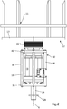
- a corresponding exemplary arrangement of motor receiving device 20, motor 16 and rotor 12 is in the Figures 2-4 shown.
- the upper end of the motor 16 is secured by fastening screws 48 (see FIG. Fig. 4 ) With a top plate 40 of the motor mounting device 20 firmly screwed.
- the opposite lower end of the motor 16 is not connected to the motor receiving device 20 and can move freely.
- the motherboard 18 can, as in Fig. 1 shown holding a support pin 26 which is integrally formed on the base plate 36 of the motor mounting device 20.
- a disk-shaped element 28 is formed, which between elastic elements 30 (s. Fig. 1 ) is fixed.
- the elastic elements 30 are acted upon along the construction axis X and thus along the axis of the support pin 26 with a biasing force.
- the rotor bearing 22 may, as in the in Fig. 4 shown example be executed as salaried support bearing. Tapered roller bearings in O arrangement are used as bearings. The tapered roller bearings of the rotor bearing 22 are in the Figures 3 and 4 only shown schematically.
- the rotor 12 may have a rotor shaft 32, which is arranged on the underside of the rotor 12 and is mounted inside the rotor bearing 22.
- the rotor shaft 32 transmits all weight forces and dynamic forces acting on the rotor 12 when rotating the rotor 12 via the rotor bearing 22 to the motor mounting device 20.
- the rotor shaft 32 is in the example shown via a keyway 34 rotatably coupled to the motor shaft 14.
- Motor shaft 32 and motor shaft 14 are arranged in the example shown coaxially to each other and the design axis X.
- the motor mounting device 20 has a plate or plate-shaped base plate 36 have. On the base plate 36 of the support pin 26 of the preferredlagers 18 is attached.
- the base plate 36 is connected via rod-shaped connecting struts 38 with a top plate 40 of the motor mounting device 20.
- the top plate 40 can - as shown - be annular. Head plate 40, base plate 36 and connecting struts 38 thus form the motor receiving device 20, which surrounds the motor 16 like a cage.
- the entire installation space of the motor mounting device 20 essentially corresponds to the installation space of the engine, so that the motor receiving device 20 with the motor 16 readily the motor 16 in a special design in the embodiment of Fig. 1 can replace.
- the motor 16 is fixed with its housing as described above with fastening screws 48 to the top plate 40, wherein its lower end is not connected to the motor receiving device 20 and can move freely.
- the brake 42 is designed as a hysteresis.
- the brake 42 is shown only schematically in the example shown. It has, as a first part, an annular electromagnet 44 for generating a magnetic field which is fixed to the top plate 40 of the motor mounting device 20.
- a ferromagnetic drum 46 is attached as a second part of the brake. The drum 46 surrounds the electromagnet 44.
- the braking forces resulting from the deceleration of the rotor 12 are thus absorbed by the top plate 40 of the motor mount 20 and do not stress the motor 16 or its motor shaft 14.
- a brake may also be used be used, which allows the return of electrical energy during the braking process in a power storage.
Landscapes
- Centrifugal Separators (AREA)
Abstract
Description
- Die Erfindung betrifft eine Zentrifuge. Sie betrifft insbesondere eine Industriezentrifuge wie sie beispielsweise zum Entölen, Trocknen, Spülen, Beschichten und Rostschützen von Werkstücken oder Metallspänen verwendet wird.
- Bei einer derartigen Zentrifuge kann der Rotor entweder unmittelbar von der Zentrifugentrommel gebildet werden oder von einer Trommelaufnahme, auf der die Zentrifugentrommel lösbar befestigt ist. Nach dem Stand der Technik sind Zentrifugen bekannt, bei denen der Rotor direkt auf der Welle eines Motors, üblicherweise eines Elektromotors, befestigt ist. Die Welle des Motors - und damit die Drehachse des Rotors - ist, zumindest im Wesentlichen, vertikal orientiert. Der Motor ist auf seiner von dem Rotor abgewandten Seite in dem Gehäuse der Zentrifuge befestigt. Die Befestigung erfolgt in der Praxis durch ein sogenanntes Fußlager. Derartige Zentrifugen zeichnen sich insbesondere durch ihren einfachen Aufbau aus. Beispiele für derartige Zentrifugen sind beispielsweise die Zentrifugen des Typs "Polar C" der Anmelderin.
- Diese Bauweise bringt es jedoch mit sich, dass Kräfte, die beim Betrieb der Zentrifuge vom Rotor in die Motorwelle eingeleitet werden, über die Lagerung des Motors aufgenommen werden müssen. Diese Kräfte resultieren insbesondere aus Unwuchten, die sich beim Betrieb derartiger Zentrifugen in der Praxis nicht völlig vermeiden lassen. Dies erfordert den Einsatz spezieller Motoren mit entsprechend stark ausgelegten Motorwellen und Lagerungen. Diese Motoren sind jedoch kostenintensiv und nur begrenzt verfügbar.
- Aus der Druschrift
EP 1 849 525 B1 ist eine Lageranordnung für eine Zentrifuge bekannt, die eine um eine Drehachse drehbar angeordnete Zentrifugentrommel, hier als Laufkorb bezeichnet, umfasst. Der Laufkorb ist über eine oben geschlossene, zylindrische Laufkorbnabe mit einer Antriebswelle über eine Aufhängung des Laufkorbs drehfest verbunden. Die Antriebswelle erstreckt sich entlang der Drehachse in einem Lagerblock und ist an eine Antriebseinheit angekoppelt. Um eine durch dynamische Kräfte hervorgerufene Lagerkraft von der Antriebswelle im Wesentlichen zu entkoppeln, ist um die Antriebswelle und innerhalb der Laufkorbnabe ein Wellenrohr angeordnet und die Lager für den Laufkorb sind zwischen der Laufkorbnabe und dem Wellenrohr angeordnet. Durch die Entlastung der Antriebswelle des Laufkorbs von dynamischen Kräften werden derartige Kräfte auch nicht in die Antriebseinheit eingeleitet. Allerdings erfordert eine derartige Lösung einen komplexen Lageraufbau und insbesondere eine geschlossene rohrförmige Laufkorbnabe, die gegenüber einem darin befindlichen Wellenrohr gelagert ist, welches sich gehäuseseitig abstützt. - Die Druckschrift
DE 43 14 440 C1 beschreibt eine entsprechende Lageranordnung für eine Zentrifuge. Hier ist ebenfalls die Zentrifugentrommel an der Motorwelle befestigt und das von der Zentrifugentrommel abgewandte Ende des Stators des Motors (Motorgehäuse) in dem Fußlager gehalten, so dass der Stator des Motors (Motorgehäuse) als verlängerte Lagerbrücke genutzt wird und Kräfte von der Zentrifugentrommel aufnimmt. - Der Erfindung liegt daher die Aufgabe zugrunde, eine Zentrifuge der vorstehend beschriebenen Art bereitzustellen, die ohne aufwändige bauliche Änderungen die Verwendung von kostengünstigeren und/oder besser verfügbaren Standardmotoren erlaubt.
- Die Aufgabe wird gelöst durch eine Zentrifuge mit den Merkmalen des Anspruchs 1. Die Merkmale der abhängigen Ansprüche betreffen vorteilhafte Ausführungsformen.
- Es wird eine Zentrifuge mit vertikaler Drehachse beschrieben, mit einem Rotor, einem unterhalb des Rotors angeordneten Motor zum Drehen des Rotors und einem Fußlager, welches den Motor und den Rotor trägt. Die Zentrifuge umfasst ferner eine Motoraufnahmeeinrichtung zur Aufnahme eines Motors, wobei der Rotor über eine Rotorlagerung drehbar an der Motoraufnahmeeinrichtung befestigt ist und wobei auf der vom Rotor abgewandten Seite der Motoraufnahmeeinrichtung das Fußlager angeordnet ist.
- Mit anderen Worten weist die erfindungsgemäße Zentrifuge weist eine Motoraufnahmeeinrichtung zur Aufnahme des Motors auf, an der der Motor befestigt ist. Zu diesem Zweck ist das Motorgehäuse am oberen Ende nahe dem Rotor an der Motoraufnahmeeinrichtung festgeschraubt. Der Rotor ist über eine Rotorlagerung drehbar an der Motoraufnahmeeinrichtung befestigt. Über diese Befestigung werden die dynamischen Kräfte des Rotors zumindest teilweise von der Motoraufnahmeeinrichtung aufgenommen und wirken nicht auf den Motor oder dessen Welle. Das Fußlager ist auf der vom Rotor und Motor abgewandten Seite der Motoraufnahmeeinrichtung angeordnet, wobei das vom Rotor abgewandten Ende des Motors nicht an der Motoraufnahmeeinrichtung und somit nicht am Fußlager befestigt ist.
- Die Kräfte, die bei der in
Fig. 1 dargestellten Zentrifuge gemäß dem Stand der Technik auf die Lagerung der Motorwelle wirken, können so von der Rotorlagerung an der Motoraufnahmeeinrichtung aufgenommen und in die Motoraufnahmeeinrichtung eingeleitet werden. Über die Motoraufnahmeeinrichtung werden diese Kräfte auf das Fußlager am unteren Ende der Motoraufnahmeeinrichtung übertragen. Das untere Ende des Motors ist frei in der Motoraufnahmeeinrichtung aufgenommen, so dass es sich bei Bewegungen des Rotors frei verlagern kann. Auf diese Weise wird die Motorwelle und die Lagerung der Motorwelle im Motor erheblich entlastet. Daher ist es möglich, auf teure und nur mit langen Lieferzeiten bestellbare Sondermotoren, deren Motorwelle und Lagerung zur Aufnahme großer Kräfte geeignet sind, zu verzichten und gewöhnliche standardisierte Elektromotoren in der Zentrifuge zu verbauen. Die Motoraufnahmeeinrichtung kann den Motor mit geringem Bauraum umgeben, weil sich der Motor während des Betriebs nur um ein geringes Maß (einige Millimeter) verlagert. Der Bauraum des Motors mit Motoraufnahmeeinrichtung ist daher unwesentlich größer als der Bauraum des Motors des Standes der Technik so dass der neue Motor mit Motoraufnahmeeinrichtung ohne weitere konstruktive Änderungen bei Zentrifugen gemäß dem Stand der Technik die bisher eingesetzten Motoren ersetzen kann. - Die Motorwelle des Motors kann in der Praxis mit dem Rotor drehfest gekoppelt sein. Es werden über diese Kopplung, zum Beispiel eine Nut-Feder-Verbindung nur die Drehmomente zwischen Motorwelle und Rotor nicht aber Querkräfte oder Biegekräfte übertragen.
- Insbesondere kann die Motoraufnahmeeinrichtung einen Motor mitsamt seinem Gehäuse und seiner Motorwellenlagerung, mit der die Motorwelle im Gehäuse des Motors gelagert ist, aufnehmen. Die Motoraufnahmeeinrichtung kann Gehäuse des Motors eng umgeben, so dass sie den Bauraum des Motors nur unwesentlich vergrößert. Bei dem Motor kann es sich beispielsweise um einen handelsüblichen Asynchronmotor handeln. Der Motor kann in der Praxis mit seinem zum Rotor hinweisenden Ende an der Motoraufnahmeeinrichtung befestigt sein. In der Praxis ist ein zum Rotor hinweisender Gehäusebereich, beispielsweise ein Lagerschild, an der Motoraufnahmeeinrichtung befestigt. Das gegenüberliegende Ende des Motors ist nicht an der Motoraufnahmeeinrichtung befestigt. Somit werden Verformungen aufgrund von Querkräften oder Biegemomenten allein von der Motoraufnahmeeinrichtung aufgenommen und nicht vom Motorgehäuse.
- Das Fußlager nimmt bei der erfindungsgemäßen Zentrifuge die Motoraufnahmeeinrichtung und nicht den Motor auf. Ein solches Fußlager befindet sich bevorzugt in Verlängerung der Drehachse des Rotors. In der Praxis kann das Fußlager wie beim Stand der Technik elastisch ausgeführt sein. Ein elastisches Fußlager hat den Vorteil, dass es der Anordnung aus Motoraufnahmeeinrichtung, Motor und Rotor der Zentrifuge, bei deren Stillstand oder niedrigen Drehzahlen, einen hinreichenden Halt verleiht, im Betrieb der Zentrifuge aber kleine Auslenkungen aufgrund der entstehenden dynamischen Kräfte erlaubt.
- Die Zentrifuge kann im Bereich des Fußlagers wie bei dem Stand der Technik gemäß
Fig. 1 Mittel zum Erkennen von Unwuchten aufweisen. Diese können sich beispielsweise durch eine unregelmäßige Befüllung des Rotors ergeben. Überschreiten die Unwuchten ein gewisses Maß, so kann dies, zu Problemen führen. Die Mittel zum Erkennen von Unwuchten können daher so eingerichtet sein, dass sie beim Überschreiten einer bestimmten Unwucht ein Warnsignal abgeben und/oder die Zentrifuge abschalten und/oder stoppen. Die Befüllung der Zentrifugentrommel muss dann so geändert werden, dass die Unwuchten vermieden werden. - Bei der Rotorlagerung kann es sich um eine Stützlagerung handeln. Die Stützlagerung kann angestellt sein. Eine Angestellte Stützlagerung hat den Vorteil, dass durch das Verspannen der Lager gegeneinander kein Lagerspiel entsteht. Dies ist insbesondere vor dem Hintergrund vorteilhaft, dass auf die Rotorlagerung wirkende Kräfte von dieser aufgenommen werden sollen, bevor diese an die Motorwelle weitergegeben werden können.
- In der Praxis kann die Rotorlagerung durch Wälzlager realisiert sein. Als Wälzlager können beispielsweise Kegelrollenlager verwendet werden. Kegelrollenlager eignen sich aufgrund des Linienkontakts zwischen Wälzkörper und Lagerringen besonders gut zur Aufnahme der auf die Rotorlagerung wirkenden Kräfte. Die Rotorlagerung kann in O-Anordnung angeordnet sein. Lager in O-Anordnung eignen sich besonders gut, um einen Kraftangriff aufzunehmen der außerhalb der Lagerstellen erfolgt. Dies ist bei einer Zentrifuge der in Rede stehenden Art beispielsweise dann der Fall, wenn der Rotor sich oberhalb der Rotorlagerung befindet. Die Unwuchten, die zu den von der Rotorlagerung aufzunehmenden Kräften führen, entstehen üblicherweise im Bereich des Rotors.
- Der Rotor kann eine Rotorwelle aufweisen. Die Rotorwelle kann innerhalb der Rotorlagerung gelagert sein. Die Rotorwelle kann koaxial zur Motorwelle angeordnet sein. Die koaxiale Anordnung beider Wellen ist insbesondere im Hinblick auf die Stabilisierung der Zentrifuge über die Kreiselkräfte der freien vertikalen Rotationsachse vorteilhaft.
- Weist der Rotor eine Rotorwelle auf, kann beispielsweise eine verdrehsteife Verbindung zwischen Motorwelle und Rotor in konstruktiv einfacher Weise realisiert werden. Beispielsweise können Motorwelle und Rotorwelle ineinandergeschoben und durch ein mit Mitnehmerelement, beispielsweise eine Passfeder, gegen Verdrehen gesichert sein. Bevorzugt wird die Motorwelle in die Rotorwelle geschoben. Hierfür geeignete Motorwellen sind häufig in Standardmotoren vorgesehen, die einfach und kostengünstig bezogen werden können.
- Vorteilhafterweise umgibt die Motoraufnahmeeinrichtung den Motor. Hierdurch kann erreicht werden, dass die Kräfte, die im Betrieb aus allen Richtungen die Rotorlagerung und damit in die Motor Aufnahmeeinrichtungen eingeleitet werden können, auch in allen Richtungen von der Motoraufnahmeeinrichtung aufgenommen werden können. Zudem wird ein weitgehend symmetrischer Aufbau der Motoraufnahmeeinrichtung um die Drehachse des Motors bzw. die Drehachse der Zentrifuge ermöglicht. Aus dem symmetrischen Aufbau erfolgt auch eine entsprechend gleichmäßige Massenverteilung der Motoraufnahmeeinrichtung.
- Die Motoraufnahmeeinrichtung kann käfigartig gestaltet sein und einen Bauraum aufweisen, der nur geringfügig größer als der Bauraum des Motors ist. Dadurch entspricht der Bauraum der Motoraufnahmeeinrichtung für einen Standard-Motor im Wesentlichen dem Bauraum des bisher eingesetzten Sondermotors. Die Anschlüsse, insbesondere die Verbindung mit dem Fußlager, können den Anschlüssen an den Sondermotors der bisherigen Ausführungsform gemäß
Fig. 1 entsprechen. Die käfigartige Motoraufnahmeeinrichtung mit dem Standardmotor kann in einfacher Weise des bisherigen Sondermotor der oben genannten Zentrifuge gemäßFig. 1 ersetzen, ohne dass weitere bauliche Änderungen der Zentrifuge erforderlich sind. Unter Beibehaltung der Gesamtkonstruktion wird somit eine zuverlässige und belastbare Zentrifuge geschaffen, die ohne Sondermotor mit einem herkömmlichen Standardmotor auskommt, weil die erheblichen dynamischen Kräfte von der Motoraufnahmeeinrichtung aufgenommen werden. - Die Motoraufnahmeeinrichtung kann eine Basisplatte aufweisen. Die Basisplatte kann mit dem Fußlager, beispielsweise durch einen Tragzapfen verbunden sein.
- Die Motoraufnahmeeinrichtung kann ferner eine Kopfplatte aufweisen. Die Kopfplatte ist an dem dem Rotor zugewandten Ende der Motoraufnahmeeinrichtung angeordnet. Der Motor kann an der Kopfplatte befestigt sein. Er ist vorzugsweise ausschließlich an der Kopfplatte befestigt, so dass sich das Motorgehäuse relativ zu anderen Bereichen der Motoraufnahmeeinrichtung frei bewegen kann. Folglich kann sich die Motoraufnahmeeinrichtung aufgrund der dynamischen Kräfte leicht verformen, ohne dass das Motorgehäuse dadurch belastet wird. Die obere Kopfplatte kann in der Praxis ringförmig gestaltet sein. Die ringförmige Gestaltung der Kopfplatte erlaubt es, die Motorwelle durch die Kopfplatte hindurchzuführen, um sie mit dem Rotor zu verbinden.
- Die Basisplatte kann mit der Kopfplatte durch Verbindungsstreben verbunden sein. Diese können sich stabförmig und/oder stangenförmig mit geringem Abstand parallel zum Gehäuse des Motors erstrecken. Mit einer derartigen Konstruktion aus Basisplatte, Kopfplatte und Verbindungsstreben lässt sich in einfacher Weise eine Motoraufnahmeeinrichtung realisieren, die den Motor käfigartig umgibt und dabei keinen Wesentlich größeren Bauraum in Anspruch nimmt als der Motor selbst.
- Weiterhin kann die Zentrifuge eine Bremse aufweisen. Die Bremse kann zwischen der Kopfplatte der Motoraufnahmeeinrichtung und dem Rotor (Zentrifugentrommel oder Trommelaufnahme) angeordnet sein. Es kann sich dabei um eine Hysteresebremse handeln. Eine Hysteresebremse ist eine Bremse, die auf der Wirkung eines Magneten oder Elektromagneten auf ein sich relativ zum Magneten bzw. Elektromagneten bewegendes ferromagnetisches Material basiert. Durch die wiederholte Ummagnetisierung des ferromagnetischen Materials entsteht ein Energieverlust. Die Bremse kann nach Art einer Trommelbremse gestaltet sein. Die Bremstrommel kann dabei an dem Rotor befestigt sein und die Magnete an der Kopfplatte. Auf diese Weise werden auch die Bremskräfte beim Abbremsen des Rotors in die Motoraufnahmeeinrichtung eingeleitet und nicht über den Motor selbst.
- Weitere praktische Ausführungsformen und Vorteile der Erfindung sind nachfolgend im Zusammenhang mit den Zeichnungen beschrieben. Es zeigen:
- Fig. 1
- eine Zentrifuge nach dem Stand der Technik in einer Schnittdarstellung.
- Fig. 2
- eine Motoraufnahmeeinrichtung mit Motor und Rotor einer erfindungsgemäßen Zentrifuge in einer Seitenansicht.
- Fig. 3
- eine Motoraufnahmeeinrichtung mit Motor und Rotor der Zentrifuge aus
Fig. 2 in einer Schnittdarstellung. - Fig. 4
- eine Detaildarstellung des in
Fig. 3 kreisförmig markierten Bereiches. - Nach dem Stand der Technik, dargestellt in
Fig. 1 , besteht eine Zentrifuge 10 aus einem Motor 16, der in einem Fußlager 18 gehalten ist und einen Rotor 12 trägt. Der Rotor 12 ist im vorliegenden Fall nicht die Zentrifugentrommel selbst sondern eine Trommelaufnahme mit einem Haltegerüst 11 und einer Aufnahmeplatte 13, auf die eine Zentrifugentrommel (nicht dargestellt) aufstellbar ist. Der Rotor 12 der Zentrifuge 10 ist direkt auf der Motorwelle 14 des Motors 16 befestigt. Nach dem Stand der Technik muss die Lagerung des Motors 16 sowohl die Gewichtskräfte der Zentrifugentrommel mit deren Füllung als auch die dynamischen Kräfte aufnehmen, die aus Unwuchten des Rotors und seiner Füllung resultieren. Diese Kräfte werden über die Motorwelle 14 in den Motor 16 eingeleitet und über das Gehäuse des Motors 16 abgeleitet. Das Gehäuse des Motors 16 ist an einem Fußlager 18 befestigt, das den Motor 16 mit dem daran befestigten Rotor 12 trägt. - Bei der hier vorgeschlagenen, neuen Zentrifuge ist der Motor 16 in einer Motoraufnahmeeinrichtung 20 aufgenommen ist. Der Rotor 12 ist mit der Motoraufnahmeeinrichtung 20 an deren oberem Ende drehbar über eine Rotorlagerung 22 verbunden. Eine entsprechende beispielhafte Anordnung aus Motoraufnahmeeinrichtung 20, Motor 16 und Rotor 12 ist in den
Figuren 2-4 dargestellt. Das obere Ende des Motors 16 ist über Befestigungsschrauben 48 (s.Fig. 4 ) mit einer Kopfplatte 40 der Motoraufnahmeeinrichtung 20 fest verschraubt. Das gegenüberliegende untere Ende des Motors 16 ist nicht mit der Motoraufnahmeeinrichtung 20 verbunden und kann sich frei bewegen. - Das an der der Motoraufnahmeeinrichtung 20 befestigte Fußlager 18 kann bei der in den
Figuren 2-4 gezeigten Anordnung entsprechend dem inFig. 1 dargestellten Stand der Technik ausgebildet sein. Das gleiche gilt für das äußere Gehäuse 24 der Zentrifuge 10 sowie deren weitere, in denFiguren 2 bis 4 nicht dargestellten Bestandteile. Folglich lässt sich die neue Motoraufnahmeeinrichtung 20 mit Standardmotor problemlos in eine existierende Zentrifuge einbauen. - Das Fußlager 18 kann, wie in
Fig. 1 dargestellt, einen Tragzapfen 26 halten, der an der Basisplatte 36 der Motoraufnahmeeinrichtung 20 angeformt ist. An dem Tragzapfen 26 ist ein scheibenförmiges Element 28 angeformt, welches zwischen elastischen Elementen 30 (s.Fig. 1 ) fixiert ist. Die elastischen Elemente 30 werden entlang der Konstruktionsachse X und damit entlang der Achse des Tragzapfens 26 mit einer Vorspannkraft beaufschlagt. - Die Rotorlagerung 22 kann wie in dem in
Fig. 4 gezeigten Beispiel als angestellte Stützlagerung ausgeführt sein. Als Lager werden Kegelrollenlager in O-Anordnung verwendet. Die Kegelrollenlager der Rotorlagerung 22 sind in denFiguren 3 und4 lediglich schematisch dargestellt. - Der Rotor 12 kann wie im gezeigten Beispiel eine Rotorwelle 32 aufweisen, die auf der Unterseite des Rotors 12 angeordnet ist und innerhalb der Rotorlagerung 22 gelagert ist. Die Rotorwelle 32 überträgt sämtliche auf den Rotor 12 wirkenden Gewichtskräfte und dynamischen Kräfte beim Drehen des Rotors 12 über die Rotorlagerung 22 auf die Motoraufnahmeeinrichtung 20. Die Rotorwelle 32 ist im gezeigten Beispiel über eine Passfederverbindung 34 drehfest mit der Motorwelle 14 gekoppelt. Motorwelle 32 und Motorwelle 14 sind im gezeigten Beispiel koaxial zueinander und zur Konstruktionsachse X angeordnet.
- Die Motoraufnahmeeinrichtung 20 weist eine platten- bzw. tellerförmige Basisplatte 36 aufweisen. An der Basisplatte 36 ist der Tragzapfen 26 des Fußlagers 18 befestigt.
- Die Basisplatte 36 ist über stabförmigen Verbindungsstreben 38 mit einer Kopfplatte 40 der Motoraufnahmeeinrichtung 20 verbunden. Die Kopfplatte 40 kann - wie dargestellt - ringförmig ausgebildet sein. Kopfplatte 40, Basisplatte 36 und Verbindungsstreben 38 bilden so die Motoraufnahmeeinrichtung 20, die den Motor 16 käfigartig umgibt. Der gesamte Bauraum der Motoraufnahmeeinrichtung 20 entspricht im Wesentlichen dem Bauraum des Motors, so dass die Motoraufnahmeeinrichtung 20 mit dem Motor 16 ohne weiteres den Motor 16 in Sonderbauform bei der Ausführungsform der
Fig 1 ersetzen kann. Der Motor 16 ist mit seinem Gehäuse wie oben beschrieben mit Befestigungsschrauben 48 an der Kopfplatte 40 befestigt, wobei sein unteres Ende nicht mit der Motoraufnahmeeinrichtung 20 verbunden ist und sich frei bewegen kann. - Zwischen dem Rotor 12 und der Motoraufnahmeeinrichtung 20 ist eine Bremse 42 angeordnet. Die Bremse 42 ist als Hysteresebremse ausgeführt. Die Bremse 42 ist im gezeigten Beispiel lediglich schematisch dargestellt. Sie weist als erstes Teil einen ringförmigen Elektromagneten 44 zur Erzeugung eines Magnetfelds auf, der an der Kopfplatte 40 der Motoraufnahmeeinrichtung 20 befestigt ist. An der Aufnahmeplatte 13 des Rotors 12 ist eine ferromagnetische Trommel 46 als zweites Teil der Bremse befestigt. Die Trommel 46 umgibt den Elektromagneten 44. Die Bremskräfte, die durch das Abbremsen des Rotors 12 entstehen, werden auf diese Weise über die Kopfplatte 40 der Motoraufnahmeeinrichtung 20 aufgenommen und belasten nicht den Motor 16 oder seine Motorwelle 14. In der Praxis kann auch eine Bremse verwendet werden, die das Rückspeisen elektrischer Energie während des Abbremsvorgangs in einen Stromspeicher ermöglicht.
- Die in der vorliegenden Beschreibung, in den Zeichnungen sowie in den Ansprüchen offenbarten Merkmale der Erfindung können sowohl einzeln als auch in beliebigen Kombinationen für die Verwirklichung der Erfindung in ihren verschiedenen Ausführungsformen wesentlich sein. Die Erfindung ist nicht auf die beschriebenen Ausführungsformen beschränkt. Sie kann im Rahmen der Ansprüche und unter Berücksichtigung der Kenntnisse des zuständigen Fachmanns variiert werden.
-
- 10
- Zentrifuge
- 11
- Aufnahmekäfig
- 12
- Rotor
- 13
- Aufnahmeplatte
- 14
- Motorwelle
- 16
- Motor
- 18
- Fußlager
- 20
- Motoraufnahmeeinrichtung
- 22
- Rotorlagerung
- 24
- Gehäuse
- 26
- stabförmiges Element
- 28
- scheibenförmiges Element
- 30
- elastisches Element
- 32
- Rotorwelle
- 34
- Passfederverbindung
- 36
- Basisplatte
- 38
- Verbindungsstrebe
- 40
- Kopfplatte
- 42
- Bremse
- 44
- Elektromagnet
- 46
- ferromagnetische Trommel
- 48
- Befestigungsschraube
- X
- Konstruktionsachse
Claims (10)
- Zentrifuge (10) mit vertikaler Drehachse, mit einem Rotor (12), einem unterhalb des Rotors (12) angeordneten Motor (16) zum Drehen des Rotors (12) und einem Fußlager (18), welches den Motor (16) und den Rotor (12) trägt,
gekennzeichnet durch eine Motoraufnahmeeinrichtung (20) zur Aufnahme eines Motors (16), wobei der Rotor (12) über eine Rotorlagerung (22) drehbar an der Motoraufnahmeeinrichtung (20) befestigt ist und wobei auf der vom Rotor (12) und Motor (16) abgewandten Seite der Motoraufnahmeeinrichtung (20) das Fußlager (18) angeordnet ist und das vom Rotor (12) abgewandten Ende des Motors (16) nicht an der Motoraufnahmeeinrichtung (20) befestigt ist. - Zentrifuge (10) nach Anspruch 1,
dadurch gekennzeichnet,
dass eine Motorwelle (14) des Motors (16) mit dem Rotor (12) drehfest gekoppelt ist. - Zentrifuge (10) nach Anspruch 1 oder 2,
dadurch gekennzeichnet,
dass die Rotorlagerung (22) eine angestellte Stützlagerung ist. - Zentrifuge (10) nach einem der vorigen Ansprüche,
dadurch gekennzeichnet,
dass der Rotor (12) eine Rotorwelle (32) aufweist, die innerhalb der Rotorlagerung (22) gelagert ist. - Zentrifuge (10) nach Anspruch 4,
dadurch gekennzeichnet,
dass die Rotorwelle (22) und die Motorwelle (14) koaxial angeordnet sind. - Zentrifuge (10) nach einem der vorigen Ansprüche,
dadurch gekennzeichnet,
dass die Motoraufnahmeeinrichtung (20) den Motor (16) umgibt. - Zentrifuge (10) nach einem der vorigen Ansprüche,
dadurch gekennzeichnet,
dass der Motor (16) mit seinem zum Rotor (12) hinweisenden Ende an der Motoraufnahmeeinrichtung (20) befestigt ist. - Zentrifuge (10) nach einem der vorigen Ansprüche,
dadurch gekennzeichnet,
dass die Motoraufnahmeeinrichtung (20) folgendes aufweist:• eine Basisplatte (36);• eine Kopfplatte (40);• mehrere Verbindungsstreben (38), die sich in Richtung der Motorwelle 14 erstrecken und deren Enden an der Basisplatte (36) einerseits und an der Kopfplatte (40) andererseits befestigt sind. - Zentrifuge (10) nach Anspruch 8,
dadurch gekennzeichnet,
dass die an der Basisplatte (36) ein Tragzapfen (26) angeordnet ist, der in einem Fußlager (18) gehalten ist. - Zentrifuge (10) nach einem der vorigen Ansprüche,
dadurch gekennzeichnet,
dass zwischen der Motoraufnahmeeinrichtung (20) und dem Rotor (12) eine Bremse (42), insbesondere eine Hysteresebremse, angeordnet ist, wobei optional ein Teil (44) der Bremse an der Kopfplatte (40) der Motoraufnahmeeinrichtung (20) und ein Teil (46) der Bremse an dem Rotor (12) befestigt ist.
Priority Applications (1)
| Application Number | Priority Date | Filing Date | Title |
|---|---|---|---|
| PL19160802T PL3552712T3 (pl) | 2018-03-15 | 2019-03-05 | Wirówka |
Applications Claiming Priority (1)
| Application Number | Priority Date | Filing Date | Title |
|---|---|---|---|
| DE102018106079.3A DE102018106079B3 (de) | 2018-03-15 | 2018-03-15 | Zentrifuge |
Publications (2)
| Publication Number | Publication Date |
|---|---|
| EP3552712A1 true EP3552712A1 (de) | 2019-10-16 |
| EP3552712B1 EP3552712B1 (de) | 2020-12-30 |
Family
ID=65717787
Family Applications (1)
| Application Number | Title | Priority Date | Filing Date |
|---|---|---|---|
| EP19160802.5A Active EP3552712B1 (de) | 2018-03-15 | 2019-03-05 | Zentrifuge |
Country Status (4)
| Country | Link |
|---|---|
| EP (1) | EP3552712B1 (de) |
| DE (1) | DE102018106079B3 (de) |
| HU (1) | HUE054097T2 (de) |
| PL (1) | PL3552712T3 (de) |
Citations (3)
| Publication number | Priority date | Publication date | Assignee | Title |
|---|---|---|---|---|
| DE4314440C1 (de) * | 1993-05-03 | 1994-06-16 | Kyffhaeuser Maschf Artern Gmbh | Zentrifugalseparator mit Schwerstanlauf |
| DE102006011895A1 (de) * | 2006-03-15 | 2007-09-20 | Westfalia Separator Ag | Separatoranordnung in sanitärer Ausführung |
| DE102013105006A1 (de) * | 2012-05-22 | 2013-11-28 | Gea Mechanical Equipment Gmbh | Antriebsvorrichtung für eine Separatoranordnung |
Family Cites Families (1)
| Publication number | Priority date | Publication date | Assignee | Title |
|---|---|---|---|---|
| EP1849525B1 (de) | 2006-04-25 | 2016-09-07 | Ferrum AG | Lageranordnung für eine Zentrifuge |
-
2018
- 2018-03-15 DE DE102018106079.3A patent/DE102018106079B3/de not_active Expired - Fee Related
-
2019
- 2019-03-05 PL PL19160802T patent/PL3552712T3/pl unknown
- 2019-03-05 EP EP19160802.5A patent/EP3552712B1/de active Active
- 2019-03-05 HU HUE19160802A patent/HUE054097T2/hu unknown
Patent Citations (3)
| Publication number | Priority date | Publication date | Assignee | Title |
|---|---|---|---|---|
| DE4314440C1 (de) * | 1993-05-03 | 1994-06-16 | Kyffhaeuser Maschf Artern Gmbh | Zentrifugalseparator mit Schwerstanlauf |
| DE102006011895A1 (de) * | 2006-03-15 | 2007-09-20 | Westfalia Separator Ag | Separatoranordnung in sanitärer Ausführung |
| DE102013105006A1 (de) * | 2012-05-22 | 2013-11-28 | Gea Mechanical Equipment Gmbh | Antriebsvorrichtung für eine Separatoranordnung |
Also Published As
| Publication number | Publication date |
|---|---|
| HUE054097T2 (hu) | 2021-08-30 |
| PL3552712T3 (pl) | 2021-06-28 |
| EP3552712B1 (de) | 2020-12-30 |
| DE102018106079B3 (de) | 2019-07-04 |
Similar Documents
| Publication | Publication Date | Title |
|---|---|---|
| DE2102679C2 (de) | Elektro-Kleinmotor für einen Lüfter | |
| DE102012009987B4 (de) | Laborkugelmühle | |
| DE4314440C1 (de) | Zentrifugalseparator mit Schwerstanlauf | |
| DE102008054842A1 (de) | Mischer | |
| DE102012009984A1 (de) | Laborkugelmühle | |
| DE102012009982A1 (de) | Laborkugelmühle | |
| DE2138898A1 (de) | Regelbarer asynchronmotor mit einem mehrfach-rotorsystem | |
| DE2814719C2 (de) | ||
| DE102012009985A1 (de) | Laborkugelmühle | |
| CH666728A5 (de) | Rotor einer windkraftanlage. | |
| EP3110557B1 (de) | Zentrifuge | |
| DE102022127864B4 (de) | Schwingungserzeuger | |
| DE102015207278A1 (de) | Elektrische Maschine und Transportvorrichtung für eine elektrische Maschine | |
| EP3552712B1 (de) | Zentrifuge | |
| DE4434221C2 (de) | Motorgetriebener Unwuchtvibrator | |
| DE1598278A1 (de) | Direkt-Antriebsvorrichtung fuer eine Ultrazentrifuge | |
| AT411288B (de) | Einrichtung zur umwandlung von elektrischer in hydraulische energie | |
| DE3119388C2 (de) | Vorrichtung zur Unterdrückung von Torsionsschwingungen | |
| DE3325566A1 (de) | Vorrichtung zum antrieb von zentrifugen | |
| DE3506628A1 (de) | Elektrische maschine | |
| EP1847337B1 (de) | Antriebsanordnung für einen in einem Gehäuse gelagerten Richtrotor einer Richtmaschine zum Geraderichten von Draht | |
| DE3642229A1 (de) | Antrieb fuer insbesondere vibrationsvorrichtungen | |
| DE666946C (de) | Waescheschleuder | |
| EP2918471B1 (de) | Einzelachsantrieb eines Schienenfahrzeugs | |
| DE4331073C1 (de) | Windenergiekonverter mit einer vorzugsweise vertikal verlaufenden Drehachse als freier Kreisel |
Legal Events
| Date | Code | Title | Description |
|---|---|---|---|
| PUAI | Public reference made under article 153(3) epc to a published international application that has entered the european phase |
Free format text: ORIGINAL CODE: 0009012 |
|
| STAA | Information on the status of an ep patent application or granted ep patent |
Free format text: STATUS: THE APPLICATION HAS BEEN PUBLISHED |
|
| AK | Designated contracting states |
Kind code of ref document: A1 Designated state(s): AL AT BE BG CH CY CZ DE DK EE ES FI FR GB GR HR HU IE IS IT LI LT LU LV MC MK MT NL NO PL PT RO RS SE SI SK SM TR |
|
| AX | Request for extension of the european patent |
Extension state: BA ME |
|
| STAA | Information on the status of an ep patent application or granted ep patent |
Free format text: STATUS: REQUEST FOR EXAMINATION WAS MADE |
|
| 17P | Request for examination filed |
Effective date: 20200407 |
|
| RBV | Designated contracting states (corrected) |
Designated state(s): AL AT BE BG CH CY CZ DE DK EE ES FI FR GB GR HR HU IE IS IT LI LT LU LV MC MK MT NL NO PL PT RO RS SE SI SK SM TR |
|
| GRAP | Despatch of communication of intention to grant a patent |
Free format text: ORIGINAL CODE: EPIDOSNIGR1 |
|
| STAA | Information on the status of an ep patent application or granted ep patent |
Free format text: STATUS: GRANT OF PATENT IS INTENDED |
|
| INTG | Intention to grant announced |
Effective date: 20200624 |
|
| GRAJ | Information related to disapproval of communication of intention to grant by the applicant or resumption of examination proceedings by the epo deleted |
Free format text: ORIGINAL CODE: EPIDOSDIGR1 |
|
| STAA | Information on the status of an ep patent application or granted ep patent |
Free format text: STATUS: REQUEST FOR EXAMINATION WAS MADE |
|
| INTC | Intention to grant announced (deleted) | ||
| GRAP | Despatch of communication of intention to grant a patent |
Free format text: ORIGINAL CODE: EPIDOSNIGR1 |
|
| STAA | Information on the status of an ep patent application or granted ep patent |
Free format text: STATUS: GRANT OF PATENT IS INTENDED |
|
| INTG | Intention to grant announced |
Effective date: 20201015 |
|
| GRAS | Grant fee paid |
Free format text: ORIGINAL CODE: EPIDOSNIGR3 |
|
| GRAA | (expected) grant |
Free format text: ORIGINAL CODE: 0009210 |
|
| STAA | Information on the status of an ep patent application or granted ep patent |
Free format text: STATUS: THE PATENT HAS BEEN GRANTED |
|
| AK | Designated contracting states |
Kind code of ref document: B1 Designated state(s): AL AT BE BG CH CY CZ DE DK EE ES FI FR GB GR HR HU IE IS IT LI LT LU LV MC MK MT NL NO PL PT RO RS SE SI SK SM TR |
|
| REG | Reference to a national code |
Ref country code: GB Ref legal event code: FG4D Free format text: NOT ENGLISH |
|
| REG | Reference to a national code |
Ref country code: DE Ref legal event code: R096 Ref document number: 502019000595 Country of ref document: DE |
|
| REG | Reference to a national code |
Ref country code: AT Ref legal event code: REF Ref document number: 1349403 Country of ref document: AT Kind code of ref document: T Effective date: 20210115 |
|
| REG | Reference to a national code |
Ref country code: CH Ref legal event code: NV Representative=s name: MICHELI AND CIE SA, CH |
|
| REG | Reference to a national code |
Ref country code: IE Ref legal event code: FG4D Free format text: LANGUAGE OF EP DOCUMENT: GERMAN |
|
| REG | Reference to a national code |
Ref country code: SE Ref legal event code: TRGR |
|
| PG25 | Lapsed in a contracting state [announced via postgrant information from national office to epo] |
Ref country code: GR Free format text: LAPSE BECAUSE OF FAILURE TO SUBMIT A TRANSLATION OF THE DESCRIPTION OR TO PAY THE FEE WITHIN THE PRESCRIBED TIME-LIMIT Effective date: 20210331 Ref country code: NO Free format text: LAPSE BECAUSE OF FAILURE TO SUBMIT A TRANSLATION OF THE DESCRIPTION OR TO PAY THE FEE WITHIN THE PRESCRIBED TIME-LIMIT Effective date: 20210330 Ref country code: RS Free format text: LAPSE BECAUSE OF FAILURE TO SUBMIT A TRANSLATION OF THE DESCRIPTION OR TO PAY THE FEE WITHIN THE PRESCRIBED TIME-LIMIT Effective date: 20201230 Ref country code: FI Free format text: LAPSE BECAUSE OF FAILURE TO SUBMIT A TRANSLATION OF THE DESCRIPTION OR TO PAY THE FEE WITHIN THE PRESCRIBED TIME-LIMIT Effective date: 20201230 |
|
| PG25 | Lapsed in a contracting state [announced via postgrant information from national office to epo] |
Ref country code: BG Free format text: LAPSE BECAUSE OF FAILURE TO SUBMIT A TRANSLATION OF THE DESCRIPTION OR TO PAY THE FEE WITHIN THE PRESCRIBED TIME-LIMIT Effective date: 20210330 Ref country code: LV Free format text: LAPSE BECAUSE OF FAILURE TO SUBMIT A TRANSLATION OF THE DESCRIPTION OR TO PAY THE FEE WITHIN THE PRESCRIBED TIME-LIMIT Effective date: 20201230 |
|
| REG | Reference to a national code |
Ref country code: NL Ref legal event code: MP Effective date: 20201230 |
|
| PG25 | Lapsed in a contracting state [announced via postgrant information from national office to epo] |
Ref country code: HR Free format text: LAPSE BECAUSE OF FAILURE TO SUBMIT A TRANSLATION OF THE DESCRIPTION OR TO PAY THE FEE WITHIN THE PRESCRIBED TIME-LIMIT Effective date: 20201230 |
|
| REG | Reference to a national code |
Ref country code: LT Ref legal event code: MG9D |
|
| PG25 | Lapsed in a contracting state [announced via postgrant information from national office to epo] |
Ref country code: EE Free format text: LAPSE BECAUSE OF FAILURE TO SUBMIT A TRANSLATION OF THE DESCRIPTION OR TO PAY THE FEE WITHIN THE PRESCRIBED TIME-LIMIT Effective date: 20201230 Ref country code: SK Free format text: LAPSE BECAUSE OF FAILURE TO SUBMIT A TRANSLATION OF THE DESCRIPTION OR TO PAY THE FEE WITHIN THE PRESCRIBED TIME-LIMIT Effective date: 20201230 Ref country code: PT Free format text: LAPSE BECAUSE OF FAILURE TO SUBMIT A TRANSLATION OF THE DESCRIPTION OR TO PAY THE FEE WITHIN THE PRESCRIBED TIME-LIMIT Effective date: 20210430 Ref country code: RO Free format text: LAPSE BECAUSE OF FAILURE TO SUBMIT A TRANSLATION OF THE DESCRIPTION OR TO PAY THE FEE WITHIN THE PRESCRIBED TIME-LIMIT Effective date: 20201230 Ref country code: LT Free format text: LAPSE BECAUSE OF FAILURE TO SUBMIT A TRANSLATION OF THE DESCRIPTION OR TO PAY THE FEE WITHIN THE PRESCRIBED TIME-LIMIT Effective date: 20201230 |
|
| REG | Reference to a national code |
Ref country code: HU Ref legal event code: AG4A Ref document number: E054097 Country of ref document: HU |
|
| PG25 | Lapsed in a contracting state [announced via postgrant information from national office to epo] |
Ref country code: IS Free format text: LAPSE BECAUSE OF FAILURE TO SUBMIT A TRANSLATION OF THE DESCRIPTION OR TO PAY THE FEE WITHIN THE PRESCRIBED TIME-LIMIT Effective date: 20210430 |
|
| REG | Reference to a national code |
Ref country code: DE Ref legal event code: R097 Ref document number: 502019000595 Country of ref document: DE |
|
| PG25 | Lapsed in a contracting state [announced via postgrant information from national office to epo] |
Ref country code: MC Free format text: LAPSE BECAUSE OF FAILURE TO SUBMIT A TRANSLATION OF THE DESCRIPTION OR TO PAY THE FEE WITHIN THE PRESCRIBED TIME-LIMIT Effective date: 20201230 Ref country code: AL Free format text: LAPSE BECAUSE OF FAILURE TO SUBMIT A TRANSLATION OF THE DESCRIPTION OR TO PAY THE FEE WITHIN THE PRESCRIBED TIME-LIMIT Effective date: 20201230 |
|
| PLBE | No opposition filed within time limit |
Free format text: ORIGINAL CODE: 0009261 |
|
| STAA | Information on the status of an ep patent application or granted ep patent |
Free format text: STATUS: NO OPPOSITION FILED WITHIN TIME LIMIT |
|
| PG25 | Lapsed in a contracting state [announced via postgrant information from national office to epo] |
Ref country code: DK Free format text: LAPSE BECAUSE OF FAILURE TO SUBMIT A TRANSLATION OF THE DESCRIPTION OR TO PAY THE FEE WITHIN THE PRESCRIBED TIME-LIMIT Effective date: 20201230 |
|
| 26N | No opposition filed |
Effective date: 20211001 |
|
| PG25 | Lapsed in a contracting state [announced via postgrant information from national office to epo] |
Ref country code: IE Free format text: LAPSE BECAUSE OF NON-PAYMENT OF DUE FEES Effective date: 20210305 Ref country code: ES Free format text: LAPSE BECAUSE OF FAILURE TO SUBMIT A TRANSLATION OF THE DESCRIPTION OR TO PAY THE FEE WITHIN THE PRESCRIBED TIME-LIMIT Effective date: 20201230 Ref country code: LU Free format text: LAPSE BECAUSE OF NON-PAYMENT OF DUE FEES Effective date: 20210305 |
|
| PG25 | Lapsed in a contracting state [announced via postgrant information from national office to epo] |
Ref country code: SI Free format text: LAPSE BECAUSE OF FAILURE TO SUBMIT A TRANSLATION OF THE DESCRIPTION OR TO PAY THE FEE WITHIN THE PRESCRIBED TIME-LIMIT Effective date: 20201230 |
|
| PGFP | Annual fee paid to national office [announced via postgrant information from national office to epo] |
Ref country code: HU Payment date: 20220227 Year of fee payment: 4 |
|
| PG25 | Lapsed in a contracting state [announced via postgrant information from national office to epo] |
Ref country code: IS Free format text: LAPSE BECAUSE OF FAILURE TO SUBMIT A TRANSLATION OF THE DESCRIPTION OR TO PAY THE FEE WITHIN THE PRESCRIBED TIME-LIMIT Effective date: 20210430 |
|
| PGFP | Annual fee paid to national office [announced via postgrant information from national office to epo] |
Ref country code: SE Payment date: 20220324 Year of fee payment: 4 Ref country code: PL Payment date: 20220225 Year of fee payment: 4 Ref country code: CZ Payment date: 20220225 Year of fee payment: 4 Ref country code: BE Payment date: 20220322 Year of fee payment: 4 |
|
| PG25 | Lapsed in a contracting state [announced via postgrant information from national office to epo] |
Ref country code: NL Free format text: LAPSE BECAUSE OF NON-PAYMENT OF DUE FEES Effective date: 20201230 Ref country code: CY Free format text: LAPSE BECAUSE OF FAILURE TO SUBMIT A TRANSLATION OF THE DESCRIPTION OR TO PAY THE FEE WITHIN THE PRESCRIBED TIME-LIMIT Effective date: 20201230 |
|
| PG25 | Lapsed in a contracting state [announced via postgrant information from national office to epo] |
Ref country code: SM Free format text: LAPSE BECAUSE OF FAILURE TO SUBMIT A TRANSLATION OF THE DESCRIPTION OR TO PAY THE FEE WITHIN THE PRESCRIBED TIME-LIMIT Effective date: 20201230 |
|
| PG25 | Lapsed in a contracting state [announced via postgrant information from national office to epo] |
Ref country code: CZ Free format text: LAPSE BECAUSE OF NON-PAYMENT OF DUE FEES Effective date: 20230305 |
|
| REG | Reference to a national code |
Ref country code: SE Ref legal event code: EUG |
|
| GBPC | Gb: european patent ceased through non-payment of renewal fee |
Effective date: 20230305 |
|
| REG | Reference to a national code |
Ref country code: BE Ref legal event code: MM Effective date: 20230331 |
|
| PG25 | Lapsed in a contracting state [announced via postgrant information from national office to epo] |
Ref country code: GB Free format text: LAPSE BECAUSE OF NON-PAYMENT OF DUE FEES Effective date: 20230305 |
|
| PG25 | Lapsed in a contracting state [announced via postgrant information from national office to epo] |
Ref country code: SE Free format text: LAPSE BECAUSE OF NON-PAYMENT OF DUE FEES Effective date: 20230306 Ref country code: HU Free format text: LAPSE BECAUSE OF NON-PAYMENT OF DUE FEES Effective date: 20230306 Ref country code: GB Free format text: LAPSE BECAUSE OF NON-PAYMENT OF DUE FEES Effective date: 20230305 |
|
| PG25 | Lapsed in a contracting state [announced via postgrant information from national office to epo] |
Ref country code: BE Free format text: LAPSE BECAUSE OF NON-PAYMENT OF DUE FEES Effective date: 20230331 |
|
| PG25 | Lapsed in a contracting state [announced via postgrant information from national office to epo] |
Ref country code: MK Free format text: LAPSE BECAUSE OF FAILURE TO SUBMIT A TRANSLATION OF THE DESCRIPTION OR TO PAY THE FEE WITHIN THE PRESCRIBED TIME-LIMIT Effective date: 20201230 |
|
| PG25 | Lapsed in a contracting state [announced via postgrant information from national office to epo] |
Ref country code: MT Free format text: LAPSE BECAUSE OF FAILURE TO SUBMIT A TRANSLATION OF THE DESCRIPTION OR TO PAY THE FEE WITHIN THE PRESCRIBED TIME-LIMIT Effective date: 20201230 |
|
| PG25 | Lapsed in a contracting state [announced via postgrant information from national office to epo] |
Ref country code: PL Free format text: LAPSE BECAUSE OF NON-PAYMENT OF DUE FEES Effective date: 20230305 |
|
| PG25 | Lapsed in a contracting state [announced via postgrant information from national office to epo] |
Ref country code: PL Free format text: LAPSE BECAUSE OF NON-PAYMENT OF DUE FEES Effective date: 20230305 |
|
| PGFP | Annual fee paid to national office [announced via postgrant information from national office to epo] |
Ref country code: DE Payment date: 20250528 Year of fee payment: 7 |
|
| PGFP | Annual fee paid to national office [announced via postgrant information from national office to epo] |
Ref country code: IT Payment date: 20250331 Year of fee payment: 7 |
|
| PGFP | Annual fee paid to national office [announced via postgrant information from national office to epo] |
Ref country code: CH Payment date: 20250401 Year of fee payment: 7 |
|
| PG25 | Lapsed in a contracting state [announced via postgrant information from national office to epo] |
Ref country code: TR Free format text: LAPSE BECAUSE OF FAILURE TO SUBMIT A TRANSLATION OF THE DESCRIPTION OR TO PAY THE FEE WITHIN THE PRESCRIBED TIME-LIMIT Effective date: 20201230 |
|
| REG | Reference to a national code |
Ref country code: CH Ref legal event code: U11 Free format text: ST27 STATUS EVENT CODE: U-0-0-U10-U11 (AS PROVIDED BY THE NATIONAL OFFICE) Effective date: 20260401 |
|
| PGFP | Annual fee paid to national office [announced via postgrant information from national office to epo] |
Ref country code: AT Payment date: 20260319 Year of fee payment: 8 |
|
| PGFP | Annual fee paid to national office [announced via postgrant information from national office to epo] |
Ref country code: FR Payment date: 20260324 Year of fee payment: 8 |