EP3552761A1 - System zum polieren und/oder fräsen von plattenkanten, verfahren zum polieren und/oder fräsen von plattenkanten und durch verbinden von polierten und/oder gefrästen kanten von plattenteilen hergestellte platte - Google Patents
System zum polieren und/oder fräsen von plattenkanten, verfahren zum polieren und/oder fräsen von plattenkanten und durch verbinden von polierten und/oder gefrästen kanten von plattenteilen hergestellte platte Download PDFInfo
- Publication number
- EP3552761A1 EP3552761A1 EP18382242.8A EP18382242A EP3552761A1 EP 3552761 A1 EP3552761 A1 EP 3552761A1 EP 18382242 A EP18382242 A EP 18382242A EP 3552761 A1 EP3552761 A1 EP 3552761A1
- Authority
- EP
- European Patent Office
- Prior art keywords
- slab
- edge
- guiding body
- tool
- polishing
- Prior art date
- Legal status (The legal status is an assumption and is not a legal conclusion. Google has not performed a legal analysis and makes no representation as to the accuracy of the status listed.)
- Withdrawn
Links
Images



Classifications
-
- B—PERFORMING OPERATIONS; TRANSPORTING
- B24—GRINDING; POLISHING
- B24B—MACHINES, DEVICES, OR PROCESSES FOR GRINDING OR POLISHING; DRESSING OR CONDITIONING OF ABRADING SURFACES; FEEDING OF GRINDING, POLISHING, OR LAPPING AGENTS
- B24B9/00—Machines or devices designed for grinding edges or bevels on work or for removing burrs; Accessories therefor
- B24B9/02—Machines or devices designed for grinding edges or bevels on work or for removing burrs; Accessories therefor characterised by a special design with respect to properties of materials specific to articles to be ground
- B24B9/06—Machines or devices designed for grinding edges or bevels on work or for removing burrs; Accessories therefor characterised by a special design with respect to properties of materials specific to articles to be ground of non-metallic inorganic material, e.g. stone, ceramics, porcelain
-
- B—PERFORMING OPERATIONS; TRANSPORTING
- B24—GRINDING; POLISHING
- B24B—MACHINES, DEVICES, OR PROCESSES FOR GRINDING OR POLISHING; DRESSING OR CONDITIONING OF ABRADING SURFACES; FEEDING OF GRINDING, POLISHING, OR LAPPING AGENTS
- B24B41/00—Component parts such as frames, beds, carriages, headstocks
- B24B41/02—Frames; Beds; Carriages
-
- B—PERFORMING OPERATIONS; TRANSPORTING
- B24—GRINDING; POLISHING
- B24B—MACHINES, DEVICES, OR PROCESSES FOR GRINDING OR POLISHING; DRESSING OR CONDITIONING OF ABRADING SURFACES; FEEDING OF GRINDING, POLISHING, OR LAPPING AGENTS
- B24B41/00—Component parts such as frames, beds, carriages, headstocks
- B24B41/06—Work supports, e.g. adjustable steadies
- B24B41/068—Table-like supports for panels, sheets or the like
-
- B—PERFORMING OPERATIONS; TRANSPORTING
- B24—GRINDING; POLISHING
- B24B—MACHINES, DEVICES, OR PROCESSES FOR GRINDING OR POLISHING; DRESSING OR CONDITIONING OF ABRADING SURFACES; FEEDING OF GRINDING, POLISHING, OR LAPPING AGENTS
- B24B7/00—Machines or devices designed for grinding plane surfaces on work, including polishing plane glass surfaces; Accessories therefor
- B24B7/07—Machines or devices designed for grinding plane surfaces on work, including polishing plane glass surfaces; Accessories therefor involving a stationary work-table
- B24B7/075—Machines or devices designed for grinding plane surfaces on work, including polishing plane glass surfaces; Accessories therefor involving a stationary work-table using a reciprocating grinding head mounted on a movable carriage
-
- B—PERFORMING OPERATIONS; TRANSPORTING
- B24—GRINDING; POLISHING
- B24B—MACHINES, DEVICES, OR PROCESSES FOR GRINDING OR POLISHING; DRESSING OR CONDITIONING OF ABRADING SURFACES; FEEDING OF GRINDING, POLISHING, OR LAPPING AGENTS
- B24B7/00—Machines or devices designed for grinding plane surfaces on work, including polishing plane glass surfaces; Accessories therefor
- B24B7/20—Machines or devices designed for grinding plane surfaces on work, including polishing plane glass surfaces; Accessories therefor characterised by a special design with respect to properties of the material of non-metallic articles to be ground
- B24B7/22—Machines or devices designed for grinding plane surfaces on work, including polishing plane glass surfaces; Accessories therefor characterised by a special design with respect to properties of the material of non-metallic articles to be ground for grinding inorganic material, e.g. stone, ceramics, porcelain
Definitions
- the present invention relates to a slab edge polishing and/or milling system, as well as to an edge polishing and/or milling method for a slab made of material capable of being machined such as stone agglomerates, ceramics, natural stones and the like.
- the system supports a tool for polishing and/or milling the edges of slabs that can be made of different materials, particularly hard materials.
- the invention refers too to machined slabs obtained through the methods as well as panels made up of joined polished and/or milled edges of slabs.
- the invention is applicable in the field of portable hand tools for polishing or milling the edges of slabs, preferably of stone agglomerates, natural stone, ceramics, and the like, that preferably find use in the fabrication and installation of kitchen countertops.
- the starting slabs are cut in pieces, and the cut edges which are used for making those joints are polished and/or milled before they are joined together with intermediation of an adhesive.
- the length of these joints might range up to more than 1 m, but more normally they are between 40 - 80 cm long, and their visual appearance for the quality of the installation work is of upmost importance.
- polishing and/or milling machines are described for example in US-7373936-B1 and US-8162726-B1 . Both documents describe tools placed on a guiding body and displaced manually for polishing or milling at least one edge of a slab. These guiding bodies of the machines are directly placed on the slab that is to be polished or milled, which is at the same time placed on a flat surface (floor, a table, a structure, etc.). Afterwards, the guiding body and the slab have to be positioned and aligned in order to guarantee that the edge is parallel to the movement of the polishing or milling head and afterwards secured with clamps.
- the known devices are placed manually by an operator it is difficult to assure that the guide will always be perfectly aligned and that the tool will move with the required parallelism to the edge of the slab and perpendicularity to the surface of the slab all through the polishing/milling process.
- the positioning and adjusting of the slab is subject to operator mistakes.
- the guiding body is directly fixed to the slab and the retention means used, mainly the clamps, do not guarantee that the different components cannot move relative to each other when the tool is moved, considering too that the polishing/milling step is inevitably accompanied by severe vibrations when the head of the tool acts on the edge of these normally hard materials.
- even highly skilled operators have difficulties to obtain reproducible results regarding the parallelism, planarity and perpendicularity of the machined edges of different slab pieces.
- the invention achieves an improvement in the machined slab edges and as a result, also in the creation of joints from those edges, by the combination of at least the following:
- the present invention provides an improved slab edge polishing and/ or milling system, as well as a method among other objects.
- this invention proposes a slab edge polishing and/or milling system, which is preferably portable, according to claim 1. Additional features of the invention are contained in claims 2 to 7.
- system object of the invention, comprises:
- the system is portable, meaning that it can be transported and used in the site where the installation of the slab or panel takes place, and it is not a fixed construction.
- the system can be transported by the operator itself or with the help of another person.
- the system allows the blocking of a slab in the correct position, between the supporting frame and the guiding body, wherein the slab is made of materials that are capable of being machined, such as stone agglomerates, natural stones, ceramics and the like.
- the slab comprises two major surfaces, normally the top and bottom surfaces, one front edge (the one intended to be machined), one rear edge (opposed to the front edge), and two lateral edges.
- the top surface will be the surface that remains visible in the application or final location of the slab (for example, the top surface of a kitchen countertop).
- the system assures through the positioning and fixing means that the relative position of the guiding body and the tool carriage with respect to the frame, and through the locking means that the relative position of the edge of the slab to be machined with respect to the movement of the head of the polishing and/or milling tool does not change during the machining process, despite the vibrations generated by the tool and despite the refrigerating/lubricating means normally used in this process.
- the system assures too that the possibility of alignment deviations or operator errors are minimized, and therefore that the edge can be precisely duplicated in another slab.
- the positioning means of the system are preferably vertical devices to allow the vertical displacement of the guiding body with respect to the supporting frame along a vertical axis (z).
- the fixing means are stops that prevent the movement of the guiding body with respect to the supporting frame in any of three orthogonal axes (x, y, z).
- the locking means of the system are placed to block the position of the slab, and therefore also the edge slab, between the supporting frame and the guiding body, once the slab has been correctly positioned.
- the system includes adjusting means for the correct positioning of the slab edge to be machined relative to the machining head as well as relative to the guiding body and supporting frame.
- the combination of adjusting means and locking means in the system assure the parallelism, planarity, linearity and perpendicularity between the edge of the slab and the different surfaces of the system and the repeatability of the results, blocking the right position of the slab in the system before and during the polishing and/or milling.
- Said locking means preferably block the slab in three orthogonal axes (x, y, z) to secure its position.
- said locking means are preferably:
- the position of the slab between the frame and the guiding body can be adjusted manually by using a measuring meter, a gauge, references, or a ruler. However, this might be subject to operator mistakes.
- the system includes adjusting means for correct and repeatable positioning of the slab to therefore achieve correct positioning, improved repeatability and to minimize the risk of operator mistakes.
- the adjusting means preferably comprise limiting devices, spacers or extended elements with two ends, that act as limiters of the position of the slab along the transversal axis (y), suitably placed on the front part of the guiding body or of the frame. These adjusting means define the distance between the edge of the slab to polish and/ or mill and the guiding body, guaranteeing the parallelism between the edge of the slab and the movement of the head of the machining tool.
- the guiding body might comprise any number of displacement guides.
- the guiding body preferably comprises at least two displacement guides, which may be parallel between them, and suitably also parallel to the front part of the guiding body.
- the guiding body comprises two parallel displacement guides which are designed to be positioned during the machining process, also substantially parallel to the edge being polished and/or milled during the machining step.
- the displacement guides serve the guiding means of the tool carriage to displace along said guiding body.
- the tool carriage comprises too guiding means intended to be located on said at least one displacement guide on the guiding body, coupled to this at least one displacement guide, allowing only a linear translational movement along said guides longitudinally parallel to the edge to be machined and preventing the carriage from moving in any other direction.
- Said carriage further comprises a tool connection for coupling the polishing and/or milling tool and it will travel along and parallel to the edge of the slab, machining the same, when the guiding means and the tool carriage move along the at least one displacement guide driven manually by the user.
- the guides may have adjustable limit switches in order to prevent the support from slipping out of the guides or for limiting the extend of the edge to be machined, preferably a limit switch on each end of at least one of the guides.
- Said guiding means are preferably at least two friction guide shoes, for example, made of Teflon, roller guide shoes with ball bearings or the like, which would be in contact with the at least one displacement guide.
- the displacement guides are located inside said guiding means, the means and the guides having complementary shapes in order to ensure tight connection between both.
- the sections of the guides and the guiding means may be rounded or curved, or dovetailed, such that they enable the displacement of the means over the guides, without risking "derailing" of the former or the slipping out of the latter.
- the tool connection on the tool carriage comprises regulating means for modifying the position or distance of the head of the polishing and/ or milling tool, allowing the tool to get closer or farther from the supporting frame and therefore from the front edge of the slab, or to regulate the pressure that the head exerts on the edge during the polishing and/or milling process.
- the carriage also comprises inclination means to modify the inclination of the head of the machining tool with respect to said edge.
- the guiding body in order to polish and/or mill the edge of the slab, is placed on top of one of the major faces or surfaces of the slab, normally the top major surface of the slab, with the at least one displacement guide, preferably two guides, projecting up from the guiding body.
- the other major face or surface of the slab is placed facing the supporting frame.
- the guiding body is suitably positioned and secured to the supporting frame through the positioning means and the fixing means comprised in the system.
- a second object of the invention is, according to claim 8, a method for polishing and/or milling a slab edge, which may use the slab edge polishing and/or milling system of the first aspect of the invention.
- step d) is done before or simultaneously with step c), or step c) might be done simultaneously or before step b), or step b) might be done simultaneously or before step a).
- the method additionally comprises a step b1) of arranging, on the guiding body and/or on the supporting frame, the adjusting means for the position of the slab.
- the method comprises additionally a step d1), which may be done after step d), of removing the adjusting means for the position of the slab from the guiding body and/or the supporting frame.
- Step c) is preferably performed so that the guiding body on the frame is blocked in any spatial direction.
- Step d) is preferably performed so that the position of the slab is locked in any spatial direction.
- the method includes a step e1) of adjusting the angle of the head of the polishing and/or milling tool relative to the top major surface of the slab, preferably to an angle of 90° ⁇ 5°, more preferably to an angle of 90° ⁇ 2°.
- the polishing and/or milling step f) is conducted by displacing the head several times along the edge.
- particle abrasives are used with a decreasing particle size sequence, more preferably with a grit size sequence of 50-100-200, and optionally finishing with grit size 400.
- the edges of the slabs obtained have improved parallelism, planarity and perpendicularity to the major surfaces of the slab.
- the repeatability of the results is also improved, with reduced risk of the occurrence of operator mistakes.
- These improved polished and/or milled edges allow joining two slab pieces to obtain panels where the joint between the slab pieces is significantly improved regarding its visual appearance. The improvement is such, that the joint is nearly imperceptible.
- the appearance of the joints between two slab pieces can be further improved by an improved method of joining two slab pieces, which is an additional aspect of the invention.
- Said method comprises polishing and/or milling the edges to be joined of the slab pieces in accordance with the invention. Then, it is followed by a step of grinding the machined edge for creating a recess on the lower part of the edge (the part of the edge distal from the top surface of the slab, the visible surface during use of the slab) for placing an adhesive for gluing the slab pieces.
- the slab piece comprises a recess where adhesive can be introduced to further be fixed or glued to other slab piece, wherein the adhesive is not visible in the joint from the top major surface of the panel obtained. Since the adhesive is only present in the lower recesses of the joint edges, the upper part of the edges can still come into intimate contact with each other.
- Another object of the invention also relates to the slabs or slab pieces with improved machined edges, obtained by the method for polishing and/or milling slab edges according to the embodiments herein.
- the invention also comprises a method for the formation of joints between slab pieces made of materials capable of being machined such as stone agglomerates, ceramics, natural stone and the like, which uses the method for polishing and/or milling slab edges according to the embodiments herein.
- Said method, object of the present invention is a method for obtaining a panel made up of at least two slab pieces, wherein:
- the invention also concerns the panel formed by joining at least two slab pieces, wherein their machined edged to be joined are obtained in accordance with the method for polishing and/or milling slab edges of the embodiments herein.
- the panels of the invention are also obtained by applying method for obtaining a panel made up of at least two slab pieces of the embodiments herein.
- relative position terms are used, such as top, bottom, horizontal, vertical, upper, lower, etc. Unless it is otherwise specified, those terms are intended to describe the position relative to the common understanding and relative to the position of the ground.
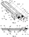
- the edge 2 polishing and/or milling system 10 for a slab 1 made of materials capable of being machined such as stone agglomerates, ceramics, natural stone and the like comprises a guiding body 200, a tool carriage 300 with a polishing and/or milling tool connection 310 and with guiding means 330 enabling the displacement of said carriage 300 along the guiding body 200, a slab supporting frame 100, positioning means 120, 240, and fixing means 241 for relative fixation of the guiding body 200 on said frame 100, and locking means 233, 234, 235 for securing the position of the slab 1 between the guiding body 200 and the frame 100.
- the polishing and/or milling system 10 is a portable system and incorporates several handles 106 for its transportation by the user.
- the supporting frame 100 preferably a frame table, and more preferably a frame table with a T shaped body 105, is placed on a surface, for example the floor or more preferably other elevated surface, standing on at least four legs 110, preferably seven legs, with height regulating means that are acted independently for leveling the supporting frame 100 on the surface.
- the guiding body 200 with the tool carriage 300 is positioned on top of the supporting frame 100 with help of the positioning means 120, 240, for example represented by vertical devices such as rods 120 arranged on the frame 100, introduced in receiving means 240 placed for that purpose on the guiding body 200, for example, rings 240 in the guiding body 200 adapted to receive the rods 120.
- the positioning means 120, 240 for example represented by vertical devices such as rods 120 arranged on the frame 100, introduced in receiving means 240 placed for that purpose on the guiding body 200, for example, rings 240 in the guiding body 200 adapted to receive the rods 120.
- Other types of positioning means are thinkable without departing from the scope of the invention.
- two limiting devices 220 acting as adjusting means along the transversal axis (y) of the system 10 are coupled to the front part or side 225 of the guiding body 200 (as shown in figures 1-4 ) or the front part or side of the supporting frame 100 (as shown in figures 13-14 ).
- the front part or side 225 of the guiding body 200 or the frame 100 refers to the part or side more proximal to the intended position of the front edge 2 to be machined of the slab 1.
- These limiting devices 220 preferably have an "L" shape to define the appropriate distance between the short leg of the "L” shaped device 220 and the front part or side 225 of the guiding body 200 or the front part of the frame 100.
- additional means for supporting the slab 1 may be placed on the frame 100, specifically on the short side of the T-shaped body 105.
- Said supporting means comprise an L piece 130 with a slot and can move perpendicular to said short side depending of the size of the slab.
- the L piece 130 comprises adjustable means 131 that displace with respect to the L piece 130 until they contact with the lower major surface 4 of the slab 1.
- the locking means of the system 10 are activated to secure/block the position of the slab 1 within the system 10, between the guiding body 200 and the supporting frame 100.
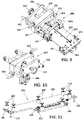
- the first locking means move along the longitudinal axis (x), that is the axis parallel to the front edge 2 of the slab 1 to be machined, and perpendicular to the lateral edges 3 of the slab 1, and are activated by moving two lateral wheels 230 that displace side carriages 231 along the guiding body 200. These side carriages 231 are displaced until they contact the lateral edges 3 of the slab 1, which are normally approximately perpendicular to the front edge 2 of the slab 1 to be machined or front edge 2 of the slab 1.
- Said carriages 231 preferably comprise also second locking means 233, 235 that work along the vertical axis (z), that is the axis perpendicular to the major surfaces 4 of the slab 1, of the system 10, and act vertically on the lateral carriages 231 to prevent the movement of the slab 1 in the vertical axis (z) with respect to the whole system.
- Said side carriages 231 comprise a side wheel 230 connected to the carriage 231 through rods 236, being one of said rods 236 an endless screw that allows the movement of the carriage along the rods 236.
- Said carriage 231 comprises a vertical plate 232 that moves under the surface 205 of the guiding body 200 that comprises the second locking means 233, 235 and means 234 for precise adjustment of the locking in the longitudinal (x) axis.
- the second locking means are preferably composed by a vertical screw 235 that vertically displaces a horizontal plate 233 that pushes upwards the slab 1 through its lower major surface.
- the precise longitudinal adjustment means 234 push the slab 1 through its lateral edges 3.
- the slab 1 is reliably secured/blocked between the guiding body 200 and the supporting frame 100, and simultaneously the guiding body 200 is fixed to the supporting frame 100.
- the components of the system 10 and the slab 1 are blocked against any movement relative to each other, even in the occurrence of strong vibrations or the operator inadvertently pushing the slab 1.
- the front edge 2 of the slab 1 will be exposed by removing the limiting devices 220.
- the head 341 of the polishing and/or milling tool 342 on the tool carriage 300 can be positioned facing the edge 2 to be machined and this head 341 can be displaced parallel to the front edge 2 of the slab 1, by moving the carriage 300 along the two parallel displacement guides 210 placed on the surface 205 of the guiding body 200.
- the displacement guides 210 are preferably covered by a suitable protection 250 such as an accordion cover that is folded when the guiding means 330 of the carriage 300 displace along the displacement guides 210 on the guiding body 200 pushing said accordion cover 250.
- a suitable protection 250 such as an accordion cover that is folded when the guiding means 330 of the carriage 300 displace along the displacement guides 210 on the guiding body 200 pushing said accordion cover 250.
- the side carriages 231 on the guiding body 200 are also preferably protected by cases 235. These protections 250, 235 help to prevent the introduction of refrigerating/lubricating liquids and/or particles arising from the polishing/milling of slab.
- the movement of the guiding means 330 placed on the tool carriage 300, and therefore the movement of the tool carriage 300, along the displacement guides 210 of the guiding body 200 can be carried out manually through the force that an operator or user exerts on the carriage 300 or on the guiding means 330, by driving or pushing the same on the guides 210.
- the tool carriage 300, or the tool connection 310 comprised in it comprises a gripping element 312, such as a grip, clamp, handle or the like, which facilitates gripping or holding the tool carriage 300 by the operator and subsequent manual driving.
- the manual polishing and/or milling tool 342 couples to the tool carriage 300 through retention means 340 on the tool connection 310.
- the tool carriage 300 and the tool 342 are configured so that it is enabled that the machining head 341 of the tool 342 can be arranged either in a resting position (far from the front edge 2 of the slab 1) or in a working position (near and facing the front edge 2 of the slab 1).
- said tool carriage 300 comprises means of articulation 322 for pivoting the connection 310, and hence the tool 342, from the resting position to the working position.
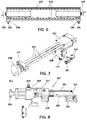
- a security device that prevents undesired articulation of the connection 310 and that locks the tool in the working position can be also included and may comprise a grip 323 with a rod connected with a chain 324, where the rod, with or without a screw, crosses the body of the tool connection 310 and the body 320 of the tool carriage 300 preventing the movement of the tool connection 310 with respect to the tool carriage 300. Further the body 320 of the tool carriage 300 has stops 321 to receive the tool connection 310 when this pivots to its resting position on to the carriage 300.
- the tool connection 310 of the carriage 300 shall allow easy coupling and uncoupling of different polishing and/or milling hand tools 342 through the retention means 340 on the connection 310.
- the tool carriage 300 might also comprise displaceable coupling means 311 of the tool, preferably in the tool connection 310 itself, so as to be able to regulate the distance between the machining head 341 of the polishing and/or milling tool 342 and the slab edge 2 to be machined, and therefore also regulate the pressure that the tool head 341 exerts against the edge 2 of the slab 1 during polishing and/or milling.
- These displaceable means 311 for the tool 342 comprise an endless screw that when it is actuated displaces the tool 342 with respect to a plate 316 on the tool connection 310.
- the retention means 340 for the tool 342 must preferably allow the coupling of different manual polishing and/or milling hand machines, without being limited by the manufacturer and the type of tool, for which it may be necessary to use an adapter between the connection and the tool.
- the system Since it is a portable system that must allow being transferred to the place where it is needed for use, usually the installation site of the slab in a bathroom or a kitchen, and since people, preferably without the help of additional machinery, carry out said transfer, the system must be, just like the tool, transportable by a user, i.e., portable.
- the system comprises fastenings or grips 106 at the ends, preferably of the supporting frame 100 and in the guiding body 200, that enable the transfer thereof by means of one or two people, depending on the dimensions of the supporting frame 100.
- the weight and dimensions of the frame 100 and the components thereof may vary depending on the dimensions of the slabs 1 to be machined and the materials of the different components of the support, which will preferably be duralumin for the frame 100, guiding body 200 and tool carriage 300.
- the tool carriage 300 comprises inclination means 317 for adjusting the inclination of the tool head 341 relative to the plane of the top major surface of the slab 1.
- the inclination means are realized by two screws 317 located in threads provided in the body 320 of the carriage 300, so that when the tool connection 310 is pivoted to the working position, the tool connection 310 rests onto the heads of these two screws 317.
- the resting position of the tool connection 310 is slightly raised or lowered, and so, the inclination angle of the tool head 341 relative to the top major surface of the slab 1 might be adjusted to an angle of 90° with very small deviation of ⁇ 5° or even ⁇ 2°.
- the screws 317 are provided with blocking means, a nut in the figures, to block further rotational movement of the screw once the inclination angle has been set.
- the machine is switched on and the front edge 2 is polished and/ or milled by moving the tool carriage 300 along the displacement guides 210 of the guiding body 200.
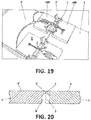
- the same system 10 After polishing and/ or milling the edge 2 of the slab 1, it is possible to use the same system 10 to, once the edge 2 has been polished and/or milled, grind said edge 2 to create a recess 5 in a portion of that edge 2, by simply changing the head 341 of the tool 342 to a grinding head.
- the system may be provided with limiters of the displacement of the tool carriage (300) to limit the length of the recess 5.
- Said recess 5 may be used to place adhesive inside it for joining two slab pieces 1, 1'.
- the panel obtained by joining the two slab pieces 1, 1', with confronted edges polished and/or milled with the previously described system 10 and method, using adhesive in the recesses 5, 5', allows obtaining improved joints of slab pieces, which are nearly visually imperceptible and with minimized risk of accumulating dirt or microorganisms.
- the joining of both slab pieces 1 is made by applying pressure between both confronted edges provided with adhesive through known means.
- devices 500 are coupled to the two slab pieces 1, 1' to be joined, by creating vacuum between the devices 500 and the surface of the slab pieces 1, 1', wherein the devices 500 are joined through rods so that they can be pneumatically approximated. Once the two slab pieces 1, 1'are joined, the excess of adhesive that might exit from the joint due to the pressure exerted is removed.
Landscapes
- Engineering & Computer Science (AREA)
- Mechanical Engineering (AREA)
- Chemical & Material Sciences (AREA)
- Ceramic Engineering (AREA)
- Inorganic Chemistry (AREA)
- Finish Polishing, Edge Sharpening, And Grinding By Specific Grinding Devices (AREA)
Priority Applications (2)
| Application Number | Priority Date | Filing Date | Title |
|---|---|---|---|
| EP18382242.8A EP3552761A1 (de) | 2018-04-09 | 2018-04-09 | System zum polieren und/oder fräsen von plattenkanten, verfahren zum polieren und/oder fräsen von plattenkanten und durch verbinden von polierten und/oder gefrästen kanten von plattenteilen hergestellte platte |
| PCT/EP2019/057180 WO2019197132A1 (en) | 2018-04-09 | 2019-03-22 | Slab edge polishing system and method, and panel obtained by joining edges |
Applications Claiming Priority (1)
| Application Number | Priority Date | Filing Date | Title |
|---|---|---|---|
| EP18382242.8A EP3552761A1 (de) | 2018-04-09 | 2018-04-09 | System zum polieren und/oder fräsen von plattenkanten, verfahren zum polieren und/oder fräsen von plattenkanten und durch verbinden von polierten und/oder gefrästen kanten von plattenteilen hergestellte platte |
Publications (1)
| Publication Number | Publication Date |
|---|---|
| EP3552761A1 true EP3552761A1 (de) | 2019-10-16 |
Family
ID=62046844
Family Applications (1)
| Application Number | Title | Priority Date | Filing Date |
|---|---|---|---|
| EP18382242.8A Withdrawn EP3552761A1 (de) | 2018-04-09 | 2018-04-09 | System zum polieren und/oder fräsen von plattenkanten, verfahren zum polieren und/oder fräsen von plattenkanten und durch verbinden von polierten und/oder gefrästen kanten von plattenteilen hergestellte platte |
Country Status (2)
| Country | Link |
|---|---|
| EP (1) | EP3552761A1 (de) |
| WO (1) | WO2019197132A1 (de) |
Cited By (1)
| Publication number | Priority date | Publication date | Assignee | Title |
|---|---|---|---|---|
| CN119057617A (zh) * | 2024-11-05 | 2024-12-03 | 西安南洋迪克整装智能家居有限公司 | 一种木质家具生产用表面打磨装置 |
Families Citing this family (2)
| Publication number | Priority date | Publication date | Assignee | Title |
|---|---|---|---|---|
| CN111716197B (zh) * | 2020-06-22 | 2024-11-08 | 佛山市顺德区佳顺隆机械有限公司 | 八边磨边机 |
| CN119928049B (zh) * | 2025-02-14 | 2025-09-05 | 广东天弼陶瓷有限公司 | 一种仿纹洞石瓷砖的喷墨打印生产工艺及生产系统 |
Citations (6)
| Publication number | Priority date | Publication date | Assignee | Title |
|---|---|---|---|---|
| DE19805410A1 (de) * | 1998-02-11 | 1999-08-26 | Zech | Verfahren und Vorrichtung zum Schleifen von harten, plattenförmigen Werkstücken |
| EP1000702A2 (de) * | 1998-11-09 | 2000-05-17 | Romeo Toniolo | Automatische Vorrichtung zum Auswechseln von Schleifscheiben in Maschinen zum Profilschneiden und Polieren von Platten aus Marmor, Granit, Glas, Gestein, Zement und dergleichen gewonnenen Werkstücken |
| EP1561555A1 (de) * | 2004-02-05 | 2005-08-10 | Sankyo Diamond Industrial Co., Ltd. | Nutenschneidgerät |
| US7373936B1 (en) | 2006-12-06 | 2008-05-20 | Viateheslav Zagorouiko | Portable finishing apparatus for hard material |
| US8162726B1 (en) | 2008-07-16 | 2012-04-24 | NSI Solutions, LLC | Edge dressing grinder tool |
| WO2014140946A1 (en) * | 2013-03-15 | 2014-09-18 | Maema S.R.L. Unipersonale | Multi-tool machine for processing products made of stone materials |
-
2018
- 2018-04-09 EP EP18382242.8A patent/EP3552761A1/de not_active Withdrawn
-
2019
- 2019-03-22 WO PCT/EP2019/057180 patent/WO2019197132A1/en not_active Ceased
Patent Citations (6)
| Publication number | Priority date | Publication date | Assignee | Title |
|---|---|---|---|---|
| DE19805410A1 (de) * | 1998-02-11 | 1999-08-26 | Zech | Verfahren und Vorrichtung zum Schleifen von harten, plattenförmigen Werkstücken |
| EP1000702A2 (de) * | 1998-11-09 | 2000-05-17 | Romeo Toniolo | Automatische Vorrichtung zum Auswechseln von Schleifscheiben in Maschinen zum Profilschneiden und Polieren von Platten aus Marmor, Granit, Glas, Gestein, Zement und dergleichen gewonnenen Werkstücken |
| EP1561555A1 (de) * | 2004-02-05 | 2005-08-10 | Sankyo Diamond Industrial Co., Ltd. | Nutenschneidgerät |
| US7373936B1 (en) | 2006-12-06 | 2008-05-20 | Viateheslav Zagorouiko | Portable finishing apparatus for hard material |
| US8162726B1 (en) | 2008-07-16 | 2012-04-24 | NSI Solutions, LLC | Edge dressing grinder tool |
| WO2014140946A1 (en) * | 2013-03-15 | 2014-09-18 | Maema S.R.L. Unipersonale | Multi-tool machine for processing products made of stone materials |
Cited By (1)
| Publication number | Priority date | Publication date | Assignee | Title |
|---|---|---|---|---|
| CN119057617A (zh) * | 2024-11-05 | 2024-12-03 | 西安南洋迪克整装智能家居有限公司 | 一种木质家具生产用表面打磨装置 |
Also Published As
| Publication number | Publication date |
|---|---|
| WO2019197132A1 (en) | 2019-10-17 |
Similar Documents
| Publication | Publication Date | Title |
|---|---|---|
| US6599064B1 (en) | Combined dowel-hole and pocket-hole drilling apparatus | |
| US7621206B2 (en) | Multi-function woodworking guide | |
| EP3552761A1 (de) | System zum polieren und/oder fräsen von plattenkanten, verfahren zum polieren und/oder fräsen von plattenkanten und durch verbinden von polierten und/oder gefrästen kanten von plattenteilen hergestellte platte | |
| US4603717A (en) | Sliding dovetail template | |
| US20030233926A1 (en) | Multi-function woodworking system | |
| US7281969B2 (en) | Tool sharpening and compound honing jig | |
| US7198042B2 (en) | Apparatus for cutting a mitered edge in stone | |
| EP4023392A1 (de) | Vorrichtung zum entgraten und beschneiden der kanten von plattenförmigen gegenständen | |
| WO1997029880A1 (en) | Miniature all-purpose tool | |
| KR20160039893A (ko) | 정밀 슬라이딩 각도 절단기 | |
| US20030233925A1 (en) | Multi-function woodworking adapter | |
| JPH03256632A (ja) | 筒状体ホルダー用心出しスタンド | |
| US6997175B2 (en) | Portable apparatus for working, shaping and polishing stone and other hard materials | |
| US7182080B1 (en) | Apparatus and method for finishing stone tiles | |
| CA3067505A1 (en) | Combined cutting and bevelling machine for slabs of stone or stone-like material | |
| CN208930062U (zh) | 一种竹木家具加工用的夹持装置 | |
| US7673662B2 (en) | Planer/sander wood machine | |
| US20220072672A1 (en) | Apparatus for cutting, grinding, and polishing work pieces at multiple axes | |
| WO2023137928A1 (zh) | 智能平面磨 | |
| EP3117957B1 (de) | Vorrichtung zur kantennachbearbeitung von fliessen | |
| KR101499538B1 (ko) | 끌, 대패 및 날 연마 가이드 | |
| AU2006201904B2 (en) | Planer/Sander Wood Machine | |
| US20100154931A1 (en) | Guide Assembly for a Cutting Tool | |
| CN208163883U (zh) | 一种木工镂铣机的工件夹紧装置 | |
| US20060211341A1 (en) | Apparatus and method for edging stone or stone tiles |
Legal Events
| Date | Code | Title | Description |
|---|---|---|---|
| PUAI | Public reference made under article 153(3) epc to a published international application that has entered the european phase |
Free format text: ORIGINAL CODE: 0009012 |
|
| STAA | Information on the status of an ep patent application or granted ep patent |
Free format text: STATUS: THE APPLICATION HAS BEEN PUBLISHED |
|
| AK | Designated contracting states |
Kind code of ref document: A1 Designated state(s): AL AT BE BG CH CY CZ DE DK EE ES FI FR GB GR HR HU IE IS IT LI LT LU LV MC MK MT NL NO PL PT RO RS SE SI SK SM TR |
|
| AX | Request for extension of the european patent |
Extension state: BA ME |
|
| STAA | Information on the status of an ep patent application or granted ep patent |
Free format text: STATUS: THE APPLICATION IS DEEMED TO BE WITHDRAWN |
|
| 18D | Application deemed to be withdrawn |
Effective date: 20200603 |