EP3552771B1 - Insert d'outil et / ou insert logement d'outil, système d'insert d'outil et / ou d'insert logement d'outil et système de stockage d'outil et / ou de logement d'outil - Google Patents
Insert d'outil et / ou insert logement d'outil, système d'insert d'outil et / ou d'insert logement d'outil et système de stockage d'outil et / ou de logement d'outil Download PDFInfo
- Publication number
- EP3552771B1 EP3552771B1 EP19152426.3A EP19152426A EP3552771B1 EP 3552771 B1 EP3552771 B1 EP 3552771B1 EP 19152426 A EP19152426 A EP 19152426A EP 3552771 B1 EP3552771 B1 EP 3552771B1
- Authority
- EP
- European Patent Office
- Prior art keywords
- tool
- insert
- tool holder
- inserts
- receiving
- Prior art date
- Legal status (The legal status is an assumption and is not a legal conclusion. Google has not performed a legal analysis and makes no representation as to the accuracy of the status listed.)
- Active
Links
Images


Classifications
-
- B—PERFORMING OPERATIONS; TRANSPORTING
- B25—HAND TOOLS; PORTABLE POWER-DRIVEN TOOLS; MANIPULATORS
- B25H—WORKSHOP EQUIPMENT, e.g. FOR MARKING-OUT WORK; STORAGE MEANS FOR WORKSHOPS
- B25H3/00—Storage means or arrangements for workshops facilitating access to, or handling of, work tools or instruments
- B25H3/003—Holders for drill bits or the like
-
- B—PERFORMING OPERATIONS; TRANSPORTING
- B25—HAND TOOLS; PORTABLE POWER-DRIVEN TOOLS; MANIPULATORS
- B25H—WORKSHOP EQUIPMENT, e.g. FOR MARKING-OUT WORK; STORAGE MEANS FOR WORKSHOPS
- B25H3/00—Storage means or arrangements for workshops facilitating access to, or handling of, work tools or instruments
- B25H3/04—Racks
-
- F—MECHANICAL ENGINEERING; LIGHTING; HEATING; WEAPONS; BLASTING
- F16—ENGINEERING ELEMENTS AND UNITS; GENERAL MEASURES FOR PRODUCING AND MAINTAINING EFFECTIVE FUNCTIONING OF MACHINES OR INSTALLATIONS; THERMAL INSULATION IN GENERAL
- F16B—DEVICES FOR FASTENING OR SECURING CONSTRUCTIONAL ELEMENTS OR MACHINE PARTS TOGETHER, e.g. NAILS, BOLTS, CIRCLIPS, CLAMPS, CLIPS OR WEDGES; JOINTS OR JOINTING
- F16B2/00—Friction-grip releasable fastenings
- F16B2/20—Clips, i.e. with gripping action effected solely by the inherent resistance to deformation of the material of the fastening
- F16B2/22—Clips, i.e. with gripping action effected solely by the inherent resistance to deformation of the material of the fastening of resilient material, e.g. rubbery material
Definitions
- the invention relates to a tool insert and/or tool holder insert according to the preamble of claim 1, a system of tool inserts and/or tool holder inserts according to the preamble of claim 12 and a tool and/or tool holder storage system according to the preamble of claim 13.
- the object of the invention consists in particular in providing a generic device with advantageous storage properties for storing tools and/or tool holders.
- the object is achieved according to the invention by the features of claims 1, 12 and 13, while advantageous configurations and developments of the invention can be found in the dependent claims.
- the invention is based on a tool insert and/or tool holder insert, in particular a tool holder insert and/or tool holder holder insert, with at least one base body, having a holder region, at least partially designed as a depression in the base body, for at least partially accommodating at least one tool and/or at least one tool a tool holder and with at least one contact element arranged at least partially within the receiving area, in particular protruding into the receiving area, to form a contacting holder for the tool and/or the tool holder.
- the tool insert and/or tool holder insert in particular the tool holder insert and/or tool holder holder insert, have side walls which are designed to be complementary to one another and run parallel to a receiving direction of the receiving area, on at least two opposite outer sides of the base body, which are provided for this purpose, at least partially with side walls further interlock tool inserts and / or tool holder inserts.
- this can create advantageous storage properties for storing tools, in particular up to a reasonable cutting edge diameter and/or spacing, and/or tool holders.
- the tool insert and/or tool holder insert could advantageously be provided for storing tools with a cutting edge diameter of at least up to 70 mm.
- a high packing density can be achieved when storing tools and/or tool holders, in particular by using an available storage surface as effectively as possible through a suitable arrangement of tool inserts and/or tool holder inserts relative to one another can, in particular with a linear arrangement of tools and bearing bases, for example mounting frames.
- a number of tool inserts and/or tool holder inserts per available storage area can be optimized and/or maximized, as a result of which a required storage area and associated storage costs can be reduced.
- a “tool holder” is to be understood in particular as a component which is provided to hold a tool and to connect the tool to a machine.
- the tool holder is designed as an interface between the tool and the machine.
- the tool holder is preferably designed as a tool chuck.
- a “tool insert” or a “tool holder insert” is to be understood in particular as a device which is intended to hold at least one tool or a tool holder in a stationary and/or position-fixed manner.
- support surfaces are used in particular, which in particular can be at least partially adapted to the outer shape of an object to be held, internal contact forces, for example due to plastic deformation of a part of the tool insert and/or the tool holder insert by the stored object and/or or frictional forces between at least one surface of the tool insert and/or the tool receiving insert and at least one surface of the stored item.
- it is held without external fastening measures such as binding, sucking, gluing, external pressing, etc.
- the tool or the tool holder is placed or set down in the receiving area of the tool insert or the tool holder insert for storage and for retrieval the tool or the tool holder is removed from the recording area of the Tool insert, or the tool holder insert removed by simply lifting.
- a “depression in the base body” is to be understood in particular as a recess in the base body, which forms a free space for receiving at least part of a body of the tool and/or the tool holder.
- a “contact element” is to be understood in particular as a part of the tool insert or the tool holder insert, which makes contact with the tool and/or the tool holder during storage.
- the tool insert and/or tool holder insert preferably has a plurality of contact elements, in particular arranged symmetrically to one another. The contact elements can be formed in one piece with the base body and/or can be separated from the base body.
- In one piece is to be understood in particular as being materially connected, such as by a welding process and/or adhesive process, etc., and particularly advantageously molded, such as by production from a single cast and/or by production in a one-component or multi-component injection molding process.
- the fact that the contact element is arranged "at least partially within the receiving area” is to be understood in particular as meaning that at least 15%, preferably at least 35%, advantageously at least 60%, preferably at least 85% and particularly preferably 100% of the contact element is within a Recording area defined space of the body is arranged.
- “Provided” should be understood to mean, in particular, specially programmed, designed and/or equipped.
- the fact that an object is provided for a specific function is to be understood in particular to mean that the object fulfills and/or executes this specific function in at least one application and/or operating state.
- two side walls are "designed to be complementary to one another" is to be understood in particular to mean that the side walls, in particular surfaces of the side walls, have shapes, in particular external shapes, which are designed and/or shaped in opposite ways to one another, with the shapes, in particular external shapes, of the side walls, in particular the surfaces of the side walls, preferably complementing one another, in particular when they are “bringed into contact”.
- two mutually complementary side walls engage in one another in the same jigsaw puzzle piece contact.
- the “receiving direction” is in particular designed as a direction which runs parallel to a main direction of movement of a tool and/or a tool holder when it is stored in the tool insert and/or the tool holder insert.
- the pick-up direction is aligned at least essentially parallel to the vertical.
- substantially parallel is to be understood here in particular as an alignment of a direction relative to a reference direction, in particular in a plane, with the direction relative to the reference direction deviating in particular by less than 8°, advantageously less than 5° and particularly advantageously less than 2°.
- a "side wall" of the tool insert and/or tool holder insert is to be understood in particular as a lateral delimitation of the base body of the tool insert and/or tool holder insert, which is arranged at least predominantly to the side of the holder area. According to the invention, the side wall is at least essentially parallel to the receiving direction and/or to the vertical in the state ready for storage.
- a “state ready for storage” is to be understood in particular as a state of the tool insert and/or tool holder insert which is intended to hold tools securely, in particular protected against tipping and/or slipping.
- Interlocking is to be understood in particular as contact between two parts and/or surfaces, in which one part and/or one surface fits into the other part and/or the other surface.
- the side walls of two tool inserts and/or two inserts overlap when they interlock Tool holder inserts, imaginary, smallest possible geometric cuboids, which just completely enclose the respective tool insert and/or tool holder insert, at least partially.
- side surfaces, in particular contact surfaces, of a side wall of the side walls designed to be complementary to one another run on at least two planes that are significantly different from one another.
- an advantageous geometry of the tool insert and/or tool holder insert can be achieved, with which, in particular, a possible packing density can be further increased.
- “Significantly different from one another” should in particular be at least angled at an angle of greater than 5°, preferably greater than 10° and preferably greater than 30° or parallel to one another and at least 3 mm, preferably at least 5 mm, preferably at least 1 cm and particularly preferably at least 2 cm apart.
- At least two of the planes defined by the side surfaces, in particular contact surfaces, of a side wall of the side walls designed to be complementary to one another run at least essentially parallel to one another.
- an advantageous geometry of the tool insert and/or tool holder insert can be achieved, with which, in particular, a possible packing density can be further increased.
- the base body in a plan view, at least essentially forms a shovel shape, a spatula shape and/or a shape of a Y which is closed at the top. In this way, in particular, an advantageous geometry of the tool insert and/or tool holder insert can be achieved, with which, in particular, a possible packing density can be further increased.
- an outer shape which consists at least essentially of a first rectangle and a second rectangle.
- the first rectangle has, in particular, side surfaces that are at least essentially of the same length.
- the second rectangle is designed in particular as an elongated rectangle.
- the second rectangle is arranged at least essentially centrally on one side of the first rectangle.
- a "spatula shape” is to be understood in particular as an outer shape which consists at least essentially of an at least essentially isosceles trapezoid and an elongated rectangle.
- the elongated rectangle is arranged at least essentially centrally on a shorter base side of the trapezium.
- a “shape of a Y” closed at the top is to be understood in particular as an external shape which consists at least essentially of a hexagon, an elongated rectangle.
- the hexagon has in particular a shape which corresponds to a rectangle from which two adjacent corners have been cut off uniformly and of the same size.
- the elongated rectangle is centered on the side of the hexagon lying between the "cut corners”.
- the short side of the elongate rectangle preferably corresponds at least essentially to the length of the side of the hexagon between the “cut corners”.
- the base body have at least one mounting element on at least one additional side wall, preferably on at least two additional, opposite side walls, for mounting on an external structural unit, in particular a mounting rail of an external structural unit running parallel to the additional side wall.
- the mounting element can be designed to be used universally, for example by being designed to be compatible with already existing systems of mounting frames.
- the mounting element could be designed to be compatible with a mounting frame which has a rake-shaped grid on at least one side of the frame, such as a commercially available insert frame for use in drawers.
- the external structural unit can in particular be designed as at least part of a mounting frame, a drawer and/or a storage compartment.
- the further side wall is preferably arranged at least essentially perpendicular to the side wall.
- the expression “essentially perpendicular” is intended here to define in particular an alignment of a direction relative to a reference direction, with the direction and the reference direction, viewed in particular in one plane, enclosing an angle of 90° and the angle has a maximum deviation of, in particular, less than 8 °, advantageously less than 5° and particularly advantageously less than 2°.
- the contact element has an outer shape which, at least in a direction perpendicular to a receiving direction of the receiving area, has an at least essentially steadily increasing and/or steadily decreasing course.
- particularly advantageous holding properties of the tool insert and/or tool holder insert can be achieved, in particular in that a surface of the contact element that contacts a tool and/or a tool holder can be optimized.
- “Essentially continuously increasing and/or decreasing” is to be understood in particular as being free from sections with a constant external shape and/or free from sections with abrupt bends, in particular with an angle of 60° or greater.
- the contact element extends into an interior of the receiving region when the tool insert and/or the tool receiving insert is in a ready-to-receive state.
- the interior of the receiving area is in particular at least largely, preferably at least completely in one spatial plane, surrounded and/or surrounded by the base body of the tool insert and/or the tool receiving insert.
- the interior of the receiving area has at least one center which, in particular seen in a top view of the tool insert and/or the tool receiving insert, is designed in particular as the center point and/or as the focal point of the receiving area.
- At least one part of the at least one contact element at least partially has an at least substantially wedge-shaped, in particular truncated wedge-shaped, outer shape.
- an at least substantially wedge-shaped, in particular truncated wedge-shaped, outer shape is proposed.
- particularly advantageous holding properties of the tool insert and/or tool holder insert can be achieved, in particular in that a surface of the contact element that contacts a tool and/or a tool holder can be optimized.
- at least the part of the contact element has an at least essentially wedge-shaped, in particular truncated wedge-shaped, outer shape, which extends into the receiving area.
- the at least one contact element has a wedge angle of at least 15°, preferably at least 20°, preferably at least 25° and particularly preferably at most 30° between two side surfaces of the contact element, holding properties of the contact element can advantageously be further optimized.
- the contact element taper in a wedge shape in the direction of an interior of the receiving area when the tool insert and/or the tool receiving insert is in a ready-to-receive state.
- particularly advantageous holding properties for example high stability, in particular holding stability of a tool and/or a tool holder in the tool insert and/or tool holder insert, can be achieved.
- a contact surface of the contact element intended for contacting at least part of a tool inserted into the receiving area and/or a tool receptacle inserted into the receiving area has at least one tangential plane in at least one partial area of the contact element, which has at least one partial component which is an assembly position of the tool insert and/or the tool holder insert runs parallel to the horizontal.
- the tool insert and/or tool holder insert forms at least one state ready for storage in the assembled position.
- a contact surface of the contact element intended for contacting at least part of a tool inserted into the receiving area and/or a tool holder inserted into the receiving area should be relative to an extrusion, in particular vertical in an assembly position of the tool insert and/or the tool holder insert a receiving opening of the receiving area delimiting the receiving area is arranged at an angle in a receiving direction of the receiving area and/or relative to an extension of the receiving area, in particular a boundary of the receiving area, in the receiving direction.
- the extrusion is to be understood in particular as an imaginary continuation of the contour of the receiving opening of the receiving area running in a vertical direction in the assembly position.
- the extension of the receiving area is to be understood in particular as an imaginary continuation of the receiving area in the vertical direction, which, in particular in an assembled state, has an angle relative to the vertical which corresponds to an average angle to the vertical of the receiving area, in particular the boundary of the receiving area formed by the base body, and /or corresponds to an angle of the recording area to the vertical at a lower end of the recording area in the vertical direction.
- an angle enclosed by the contact surface and the extrusion of the receiving opening is at least 1°, preferably at least 3°, advantageously at least 5°, preferably at least 7° and particularly preferably at least 10°
- a high holding force and/or holding stability of an embedded Tool and / or a stored tool holder in particular depending on the weight of the tool and / or the tool holder can be achieved.
- the angle can be adapted to the dead weight.
- a holding force is thereby advantageously generated by an interaction with a force of gravity. In the case of such an adjustment, a higher intrinsic weight in particular causes a larger angle to the vertical.
- a further angle enclosed by the contact surface and the extension of the receiving area, in particular the boundary of the receiving area is at least 1°, preferably at least 3°, advantageously at least 5°, preferably at least 7° and particularly preferably at least 10°, can advantageously a holding force and/or holding stability of the stored tool and/or a stored tool holder can be further optimized.
- a high degree of stability of the tool insert and/or the tool holder insert can be achieved.
- the angle formed by the contact surface and the extrusion of the receiving opening and/or the further angle formed by the contact surface and the extension of the receiving area, in particular the delimitation of the receiving area is at most 3°, preferably at most 5°, advantageously at most 7°, preferably at most 15° and particularly preferably at most 25°, a good holding force and/or holding stability of the stored tool and/or a stored tool holder can advantageously be achieved.
- the angle and the further angle are of different sizes.
- advantageous properties in terms of stability can be achieved.
- the fact that the angle and the further angle are "of different sizes" should be understood in particular to mean that the angle and the further angle, at least in a state ready for storage, are at least 1°, preferably at least 2°, preferably at least 3° to the vertical and particularly preferably span a different angle by at least 5°.
- the contact surface is at least partially curved.
- particularly advantageous storage properties for storing tools and/or tool holders can be created, for example an overall contact area can advantageously be further optimized.
- a total contact surface and/or holding force can advantageously be optimized depending on an insertion depth of a stored tool and/or a stored tool holder.
- the phrase "bent in one direction" should be understood in particular to mean that an object and/or a surface describes an arc when viewed along the direction and/or that the Object and/or the surface has a radius of curvature when viewed perpendicularly to the direction.
- the contact surface is bent at least essentially in a direction parallel to a receiving direction of the receiving area, an overall contact surface when holding a tool and/or a tool holder can advantageously be further reduced.
- the at least one contact element is formed separately from the base body.
- flexibility can advantageously be increased, for example in that a plurality of different contact elements can be combined with the same base body.
- the at least one contact element is designed to be exchangeable, flexibility can advantageously be further increased as a result, for example in that, depending on the type of object to be stored, suitable contact elements can be combined with the base body prior to storage.
- suitable contact elements can be combined with the base body prior to storage.
- individual faulty and/or worn contact elements can advantageously be easily replaced, as a result of which the costs and effort involved in a repair can be reduced in particular.
- the contact elements can be pushed into the base body and/or removed from the base body, for example by means of rails.
- a clip connection for example, can be provided for fastening the contact elements to the base body.
- At least one contact element is at least partially flexibly deformable and/or has at least one at least partially flexibly deformable contact surface.
- the flexibly deformable contact element could, for example, be designed at least partially as a bending spring and/or as a torsion spring.
- the flexibly deformable contact element and/or the flexibly deformable Contact surface may be formed at least partially from an elastically compressible material, such as an elastomer.
- the tool insert and/or the tool holder insert has at least a plurality of contact elements, preferably at least three, advantageously at least four and preferably at least five contact elements.
- the contact elements are preferably arranged at least partially regularly on an edge of the receiving opening.
- a center of the receiving opening and/or the receiving area in particular a point of intersection of at least two normal vectors of contact surfaces of two contact elements, in particular seen in a plan view, is arranged laterally offset in the base body.
- advantageous storage properties for storing tools and/or tool holders can be created.
- a high packing density can be achieved when storing tools and/or tool holders, in particular in that an available storage surface can be used as effectively as possible through a suitable arrangement of tool inserts and/or tool holder inserts relative to one another.
- a number of tool inserts and/or tool holder inserts per available storage area can be optimized and/or maximized.
- “Laterally offset in the base body” is to be understood as meaning, in particular when viewed from above, with unequal distances from at least two opposite lateral boundaries, in particular the further side walls, of the base body.
- a center of the receiving opening and/or the receiving area does not overlap with a center of gravity of the base body.
- a system of tool inserts and/or tool holder inserts with at least two tool inserts and/or tool holder inserts is proposed, the tool inserts and/or Tool holder inserts are arranged relative to one another in such a way that side walls of the at least two tool inserts and/or tool holder inserts at least partially interlock.
- advantageous storage properties for storing tools and/or tool holders can be created.
- a high packing density can be achieved when storing tools and/or tool holders, in particular in that an available storage surface can be used as effectively as possible through a suitable arrangement of tool inserts and/or tool holder inserts relative to one another.
- any number of tool inserts and/or tool holder inserts can be arranged in a row with at least two and/or at least partially three tool inserts and/or tool holder inserts interlocking.
- each tool insert and/or tool holder insert is intended to engage in one another on two opposite sides, each with a further tool insert and/or tool holder insert, with adjacent tool inserts and/or tool holder inserts each being arranged rotated by 180° in a horizontal plane.
- the receiving openings of tool inserts and/or tool receiving inserts arranged in a row lie on two non-overlapping parallel straight lines.
- a tool insert and/or tool holder insert system with at least one tool insert and/or tool holder insert and with at least one further contact element, in particular a further set of interchangeable contact elements, which is designed differently from the contact element, is proposed.
- flexibility can advantageously be increased, in particular by having different tools and/or tool holders, in particular tools and/or tool holders with different ones Diameters, in particular shank diameters, can be stored in the tool insert and/or tool holder insert system.
- the further contact element has an external shape that differs from the contact element, for example a different contact surface, a different angle, preferably a wedge angle, and/or a different extension in at least one spatial plane.
- tool holders of sizes SK30, SK40, SK50 and/or HSK-A63 could be storable in the tool insert and/or tool holder insert system, with contact elements being used in particular for storing smaller tool holders, which are longer, i.e. further into the interior of the holder area extend than to store larger tool holders.
- the smaller tool holders hold tools with a large cutting edge diameter, for example greater than 70 mm
- a tool insert and/or tool holder insert system with suitable contact elements and an enlarged holder area can advantageously achieve an advantageous packing density, in particular by excluding two tools and/or tools from touching each other. or tool holders, are made possible.
- At least one further contact element in particular at least the contact elements of at least the further set of contact elements, has a maximum horizontal transverse extent in an assembly position of the tool insert and/or the tool holder insert, which is at least 50% larger, preferably at least twice as large, preferably at least is three times as large and particularly preferably at least four times as large as the maximum horizontal transverse extent of the at least one contact element.
- flexibility can advantageously be increased, in particular in that different tools and/or tool holders, in particular tools and/or tool holders with different diameters, in particular shank diameters, can be stored in the tool insert and/or tool holder insert system.
- Under a "max horizontal transverse extension" of an object should be understood in particular as a longest side length of a smallest geometric cuboid, which just completely encloses the object and which has at least one side edge running parallel to a horizontal line.
- At least part of a further contact element in particular at least part of one of the contact elements of the at least one further set of contact elements, in an assembly position of the tool insert and/or the tool holder insert has a maximum horizontal transverse extent protruding into the holder area, which at least 10%, preferably at least 15%, advantageously at least 20%, preferably at least 25% and particularly preferably at least 30% corresponds to a maximum horizontal transverse extension of the recording area.
- flexibility can advantageously be further increased, in particular in that tools and/or tool holders with reduced diameters, in particular shank diameters, can be securely held in the tool insert and/or tool holder insert system.
- a tool and/or tool holder storage system with at least one tool insert and/or tool holder insert, with a system of tool inserts and/or tool holder inserts and/or with a tool insert and/or tool holder insert system and with a tool storage unit is proposed, which has at least one mounting rail for assembly has at least one tool insert and/or a tool holder insert.
- an advantageous storage device for tools and/or tool racks can be created, which in particular allows storage with a high packing density.
- the tool storage unit is designed as a tool cabinet, a tool trolley and/or a shelf for a tool presetter and/or tool measuring device and/or as at least part of a tool cabinet, a tool trolley and/or a shelf for a tool presetter and/or tool measuring device.
- the mounting rail is movably mounted relative to a base unit of the tool storage unit.
- the tool inserts and/or tool holder inserts are positioned in the mounting rail such that receiving openings of the receiving areas of the tool inserts and/or tool holder inserts are arranged in two at least essentially parallel rows that are laterally offset from one another.
- a tool and/or tool holder storage system can advantageously be created which has a particularly advantageous packing density for stored tools and/or tool holders, as a result of which an advantageous space saving can be achieved in particular.
- the rows that are laterally offset relative to one another are arranged in a common plane parallel to a horizontal plane in the assembled position.
- the tool insert and/or tool holder insert according to the invention, the system of tool inserts and/or tool holder inserts according to the invention and the tool and/or tool holder bearing system according to the invention should not be limited to the applications and embodiments described above.
- the tool insert and/or tool holder insert according to the invention, the system of tool inserts and/or tool holder inserts according to the invention and the tool and/or tool holder bearing system according to the invention can have a number of individual elements, components and units that differs from the number specified herein in order to fulfill a function described herein exhibit.
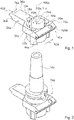
- the tool insert and/or tool holder insert 74a is designed as a tool storage insert and/or tool holder storage insert.
- the tool insert and/or tool holder insert 74a has a base body 10a.
- the base body 10a has the shape of a Y 38a closed at the top (cf. also Figure 5c ).
- the base body 10a has a receiving area 14a.
- the receiving area 14a is designed as a depression 12a in the base body 10a.
- the recess 12a is formed continuously through the base body 10a.
- the receiving area 14a and/or the depression 12a can also be designed to be closed off at the bottom.
- the receiving area 14a is provided for at least partially receiving at least one tool and/or at least one tool holder 16a (cf. 2 ).
- a tool and/or a tool holder 16a is picked up, the tool and/or the tool holder 16a is introduced into the holding area 14a from above in a holding direction 24a.
- the receiving portion 14a is arranged in a wide part of the shape of the closed-top Y 38a.
- the receiving area 14a is arranged in a bifurcated part of the Y of the shape of the Y 38a closed at the top.
- the receiving area 14a has an interior 46a.
- the interior 46a of the receiving area 14a is to be understood as a free volume formed by the recess 12a.
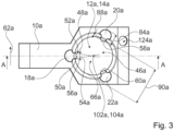
- the receiving area 14a has a center 102a (cf. 3 ).
- the center 102a of the receiving area 14a is arranged centrally in the receiving area 14a.
- the receiving area 14a has a receiving opening 66a.
- the receiving opening 66a is formed in a circular shape.
- the receiving opening 66a delimits the receiving area 14a in pick-up direction 24a.
- the receiving opening 66a has a center 104a (cf. 3 ).
- the center 102a of the receiving area 14a and the center 104a of the receiving opening 66a are both located on a central axis 106a.
- the center 102a of the receiving area 14a is arranged laterally offset in the base body 10a.
- the center 104a of the receiving opening 66a is arranged laterally offset in the base body 10a.
- the receiving opening 66a has a transverse extension 90a (cf. 3 ).
- the transverse extent 90a of the receiving opening 66a runs parallel to a horizontal line 62a.
- the transverse extent 90a of the receiving opening 66a corresponds to a diameter of the circular receiving opening 66a.
- the base body 10a has a mounting element 44a.
- the mounting element 44a is arranged on a further side wall 40a, 42a of the base body 10a.
- the mounting element 44a is provided for mounting the base body 10a on an external structural unit.
- the mounting element 44a is designed as a mounting rail.
- the mounting element 44a can also be designed as a hole, for example a screw and/or rivet hole, as a latching element and/or as another element which is suitable for mounting on an external structural unit.
- the base body 10a can be mounted without screws on an external structural unit, for example a mounting frame.
- the base body 10a has a latching element (not shown).
- the latching element is provided for mounting the base body 10a on the external structural unit, for example the mounting frame.
- the locking element is arranged on a further side wall 42a opposite the mounting element 44a.
- the latching element is intended to form a form fit with a corresponding latching element of the mounting frame.
- a lower grip can be provided, which engages in at least part of the structural unit and/or at least engages under the mounting frame.
- attachment of the base body 10a to the external unit, in particular the Mounting frame be provided by means of a screw.
- the base body 10a is beveled on the sides of the other side walls 40a, 42a relative to the horizontal 62a.
- the bevel is provided for attaching a label.
- the base body 10a has a domed or sunken area 124a in the beveled area. Domed or lowered area 124a is provided for attaching a label, for example a sticker, in particular in a non-slip manner.
- the tool insert and/or tool holder insert 74a has side walls 26a, 28a.
- the side walls 26a, 28a are designed to be complementary to one another.
- the side walls 26a, 28a run parallel to a receiving direction 24a of the receiving area 14a.
- the side walls 26a, 28a are arranged on two opposite outer sides of the base body 10a.
- the side walls 26a, 28a, which are complementary to one another, are intended to partially interlock with side walls of further tool inserts and/or tool-receiving inserts.
- the side walls 26a, 28a have a stepped shape, in particular a sloping stepped shape.
- the side wall 26a has side surfaces 30a, 32a.
- the side surfaces 30a, 32a form contact surfaces to another side wall.
- the side surfaces 30a, 32a are flat.
- the side faces 30a, 32a run perpendicular to a horizontal surface of the base body 10a.
- the side surfaces 30a, 32a are connected to one another via a further side wall forming a further side surface.
- the tool insert and/or tool holder insert 74a has a plurality of contact elements 18a, 20a, 22a.
- the tool insert and/or tool holder insert 74a has three contact elements 18a, 20a, 22a.
- the contact elements 18a, 20a, 22a are provided to form a contacting mount for the tool and/or the tool holder 16a.
- the contact elements 18a, 20a, 22a each have a contact surface 56a, 58a, 60a.
- the contact surfaces 56a, 58a, 60a are provided for contacting a part of the tool inserted into the receiving area 14a and/or the tool holder 16a inserted into the receiving area 14a.
- the contact surfaces 56a, 58a, 60a are flat.
- the contact surfaces 56a, 58a, 60a can be at least partially curved and/or structured (cf. also 10 ).
- the contact element 18a, 20a, 22a is partially flexibly deformable.
- the contact surface 56a, 58a, 60a is partially flexibly deformable.
- the contact elements 18a, 20a, 22a are partially arranged within the receiving area 14a.
- the contact elements 18a, 20a, 22a protrude into the receiving area 14a.
- the contact element 18a, 20a, 22a extends into the interior 46a of the receiving region 14a.
- the part of the contact element 18a, 20a, 22a which extends into the interior 46a of the receiving area 14a has a transverse extent 88a.
- the contact element 20a shown corresponds to about 5% of a transverse extent 90a of the receiving opening 66a.
- a total transverse extent 84a of the mounted contact element 20a in a horizontal direction is approximately 30% of the transverse extent 90a of the receiving opening 66a.
- the part of the contact element 18a, 20a, 22a which extends into the interior 46a of the receiving area 14a has a partially wedge-shaped outer shape 48a.
- the partially wedge-shaped outer shape 48a is formed as a truncated wedge shape.
- the contact element 18a, 20a, 22a runs in a ready-to-receive state of the Tool insert and / or the tool holder insert 74a wedge-shaped towards the interior 46a of the receiving area 14a.
- the contact element 18a, 20a, 22a has two side faces 50a, 52a.
- the wedge-shaped outer shape 48a of the contact elements 18a, 20a, 22a spans a wedge angle 54a between the two side surfaces 50a, 52a of the contact element 18a, 20a, 22a.
- the wedge angle 54a is 25°.
- the contact element 18a, 20a, 22a is formed separately from the base body 10a.
- the contact element 18a, 20a, 22a is designed to be exchangeable.
- the base body 10a has a receiving element 114a for receiving a contact element 18a, 20a, 22a.
- the receiving element 114a is designed as a rail.
- the receiving element 114a preferably has a latching mechanism for latching the contact element 18a, 20a, 22a after it has been pushed into the receiving element 114a in a latched position.
- a latching mechanism can be implemented, for example, by a positive fit of flexible plastic parts into one another.
- FIG. 4 shows a side sectional view of a tool insert and/or tool receiving insert 74a along an in 3 indicated sectional plane A.
- the contact surfaces 56a, 58a, 60a have a tangential plane 108a in a partial area of the contact element 18a, 20a, 22a.
- the tangent plane 108a has a normal vector 112a.
- the tangential plane 108a in particular the normal vector 112a of the tangential plane 108a, has a partial component 110a which runs parallel to the horizontal 62a in an assembly position of the tool insert and/or the tool receiving insert 74a.
- the tangential plane 108a in particular the normal vector 112a of the tangential plane 108a, has a sub-component 116a which, in an assembly position of the tool insert and/or the Tool holder insert 74a perpendicular to the horizontal 62a.
- the normal vector 112a of the tangential plane 108a forms a linear combination of the vertical sub-component 116a and the horizontal sub-component 110a.
- the contact element 18a, 20a, 22a has an external shape.
- the outer shape of the contact element 18a, 20a, 22a has a continuously increasing course in a direction perpendicular to the receiving direction 24a of the receiving area 14a.
- the outer shape could have a continuously decreasing profile and/or a profile that alternates between a constant increase and a constant decrease at least once, preferably several times.
- the contact surface 56a, 58a, 60a of the contact element 18a, 20a, 22a is angled relative to an extrusion 64a of the receiving opening 66a.
- An angle 70a enclosed by the contact surface 56a, 58a, 60a and the extrusion 64a of the receiving opening 66a is 3°.
- the contact surface 56a, 58a, 60a of the contact element 18a, 20a, 22a is arranged at an angle relative to an extension 68a of the receiving area 14a in the receiving direction 24a.
- a further angle 72a which the contact surface 56a, 58a, 60a and the extension 68a of the receiving area 14a enclose is 2°.
- the angle 70a which the contact surface 56a, 58a, 60a and the extrusion 64a of the receiving opening 66a enclose and the further angle 72a which the contact surface 56a, 58a, 60a and the extension 68a of the receiving area 14a enclose are of different sizes.
- the angle 70a formed by the contact surface 56a, 58a, 60a and the extrusion 64a of the receiving opening 66a is greater than the further angle 72a formed by the contact surface 56a, 58a, 60a and the extension 68a of the receiving area 14a.
- figure 5 shows different shapes of the tool insert and/or tool holder insert 74'a, 74"a, 74′′′a in a plan view.
- Figure 5a shows a tool insert and / or tool holder insert 74'a, which one Blade shape 34a forms.
- Figure 5b shows a tool insert and/or tool holder insert 74"a, which forms a spatula shape 36a.
- Figure 5c shows a tool insert and/or tool holder insert 74′′′a, which forms a shape of a Y 38a closed at the top.
- FIG. 6 shows a system 76a of tool inserts and/or tool holder inserts 74a, 78a with at least two tool inserts and/or tool holder inserts 74a, 78a.
- the tool inserts and/or tool holder inserts 74a, 78a are arranged relative to one another in such a way that side walls 26a, 28a of the two tool inserts and/or tool holder inserts 74a, 78a partially mesh.
- the first tool insert and/or tool holder insert 74a is rotated through 180° in the horizontal plane and is arranged adjacent to the second tool insert and/or tool holder insert 78a. Further systems of tool inserts and/or tool holder inserts can be arranged on both sides of the system 76a.
- Arranging a plurality of tool inserts and/or tool holder inserts 74a, 78a in systems 76a according to the invention forms an arrangement in which tools and/or tool holders 16a can be stored in two laterally offset rows 98a, 100a.
- a particularly large number of tools and/or tool holders 16a can advantageously be accommodated in a small space along a direction parallel to the rows 98a, 100a.
- the tool and/or tool holder storage system 96a has a tool storage unit 92a.
- the tool storage unit 92a is designed as a mobile trolley.
- the tool storage unit 92a has mounting rails 94a.
- the mounting rails 94a are provided for mounting tool inserts and/or tool holder inserts 74a, 78a.
- the Mounting rail 94a is for fastening the tool inserts and/or tool holder inserts 74a, 78a by means of their mounting element 44a intended.
- the tool storage unit 92a forms an external structural unit.
- Systems 76a of tool inserts and/or tool holder inserts 74a, 78a can be mounted in a mounting rail 94a of the tool storage unit 92a.
- the tool inserts and/or tool holder inserts 74a, 78a of a system 76a of tool inserts and/or tool holder inserts 74a, 78a are positioned in the mounting rail 94a in such a way that receiving openings 66a of the receiving regions 14a of the tool inserts and/or tool holder inserts 74a, 78a are in two parallel positions, lateral to one another staggered rows 98a, 100a.
- FIG. 8 shows a tool insert and/or tool holder insert system 80a with at least one tool insert and/or tool holder insert 74a.
- the tool insert and/or tool holder insert system 80a has a further contact element 82a.
- the further contact element 82a is part of a further set of interchangeable contact elements.
- the further contact element 82a is designed differently from the contact element 18a, 20a, 22a.
- the further contact element 82a has a maximum horizontal transverse extent 86a in an assembly position of the tool insert and/or the tool receiving insert 74a.
- the maximum horizontal transverse extent 86a of the further contact element 82a is at least 50% greater than the maximum horizontal transverse extent 84a of the contact element 18a, 20a, 22a.
- That part of the additional contact element 82a which protrudes into the receiving area 14a when the tool insert and/or the tool receiving insert 74a is in a mounted position when the additional contact element 82a is mounted has a horizontal transverse extent 88a which corresponds to at least 10% of a maximum horizontal transverse extent 90a of the receiving area 14a (cf. also 3 ).
- FIG. 9 shows a detail of a schematic sectional view of a tool insert and/or tool holder insert 74b with an alternative contact element 18b along a sectional plane A (cf. 3 ).
- the contact element 18b is curved.
- the contact element 18b has a contact surface 56b.
- the contact surface 56b is curved.
- the contact element 18b is flexible.
- the contact element 18b forms a bending spring.
- the bending spring is essentially biased in a spring direction 118b.
- the spring direction 118b runs essentially perpendicularly to a receiving direction 24b in which a tool and/or a tool holder 16b is moved when it is stored in a receiving region 14b of the tool insert and/or tool holder insert 74b.
- the contact surface 56b is bent in a direction parallel to the receiving direction 24b of the receiving area 14b.
- a radius of curvature 120b of the curvature of the bent or curved contact surface 56b lies in a plane with the cutting plane A.
- FIG. 10 shows a cross section through the contact element 18b along an in 9 indicated sectional plane B.
- the contact surface 56b is bent in a direction parallel to the receiving direction 24b of the receiving area 14b.
- Another radius of curvature 122b of the curvature of the bent or curved contact surface 56b lies in one plane with the cutting plane B.
- FIG. 11 shows an alternative tool insert and/or tool holder insert 74c that is not according to the invention.
- the tool insert and/or tool holder insert 74c has a rectangular shape.
- the tool insert and/or tool holder insert 74c has a holder area 14c.
- the receiving area 14c is arranged centrally in a base body 10c of the tool insert and/or tool receiving insert 74c.
Landscapes
- Engineering & Computer Science (AREA)
- Mechanical Engineering (AREA)
- General Engineering & Computer Science (AREA)
- Purses, Travelling Bags, Baskets, Or Suitcases (AREA)
- Workshop Equipment, Work Benches, Supports, Or Storage Means (AREA)
- Cutting Tools, Boring Holders, And Turrets (AREA)
Claims (13)
- Insert d'outil et/ou insert de porte-outil (74a-b, 78a-b), en particulier insert-dépôt d'outil et/ou insert-dépôt de porte-outil,avec au moins un corps de base (10a-b) ayant précisément une zone de logement (14a-b), formée au moins partiellement comme enfoncement (12a-b) dans le corps de base (10a-b), pour au moins partiellement recevoir au moins un outlil et/ou au moins un porte-outil (16a-b),avec au moins un élément de contact (18a-b, 20a-b, 22a-b), disposé au moins partiellement dans la zone de logement (14a-b) et projetant dans la zone de logement (14a-b), pour former un support-contactant de l'outil et/ou du porte-outil (16a-b),et avec des parois latérales (26a-b, 28a-b), formées complémentairement l'une à l'autre et s'étendant en parallèle à une direction de logement (24a-b) de la zone de logement (14a-b), sur au moins deux faces extérieures opposées du corps de base (10a-b), lesdites parois latérales (26a-b, 28a-b) ayant des surfaces latérales (30a-b, 32a-b) qui forment des surfaces de contact,caractérisé en ce que les surfaces latérales (30a-b, 32a-b) d'une paroi latérale (26a-b) des parois latérales (26a-b, 28a-b) formées complémentairement l'une à l'autre, qui forment les surfaces de contact, s'étendent sur au moins deux plans sensiblement différents l'un de l'autre et s'étendant au moins sensiblement parallèlement l'un à l'autre,les parois latérales (26a-b, 28a-b) avec les surfaces latérales (30a-b, 32a-b) formant les surfaces de contact étant prévues pour s'engrener au moins partiellement avec des parois latérales (26a-b, 28a-b) des autres inserts d'outil et/ou inserts de porte-outil (74a-b, 78a-b), qui aussi comprennent des surfaces latérales (30a-b, 32a-b) formant les surfaces de contact, d'une telle manière que - dans l'engrenage des parois latérales (26a-b, 28a-b) de deux des inserts d'outil et/ou inserts de porte-outil (74a-b, 78a-b) - les parallélépipèdes rectangles géométriques imaginaires les plus petits possibles, chacun desquels tout juste entoure complètement un insert d'outil et/ou insert de porte-outil (74a-b, 78a-b) des deux inserts d'outil et/ou inserts de porte-outil (74a-b, 78a-b), se chevauchent au moins partiellement,où la zone de logement (14a-b) comprend précisément une ouverture-logement (66a-b),où un centre (104a-b) de l'ouverture-logement (66a-b) et/ou de la zone de logement (14a-b) est disposé dans le corps de base (10a-b) en décalage latéral et où l'insert d'outil et/ou l'insert de porte-outil (74a-b, 78a-b) est formé d'une telle manière que - dans un alignement des inserts d'outil et/ou inserts de porte-outil (74a-b, 78a-b) qui sont respectivement tournés par 180° dans un plan horizontal - les ouvertures-logement (66a-b) des inserts d'outil et/ou inserts de porte-outil (74a-b, 78a-b) alignés soient situées sur deux lignes droites parallèles sans chevauchement, en alignements (98a-b, 100a-b) décalés l'un par rapport à l'autre.
- Insert d'outil et/ou insert de porte-outil (74a-b, 78a-b) selon la revendication 1, caractérisé en ce que vu en plan, le corps de base (10a-b) forme au moins sensiblement une forme de pelle (34a-b), une forme de couteau à enduire (36a-b) et/ou une forme d'i grec fermé en haut (38a-b).
- Insert d'outil et/ou insert de porte-outil (74a-b, 78a-b) selon la revendication 1 ou 2, caractérisé en ce que l'élément de contact (18a-c, 20a-c, 22a-c) présente une forme extérieure ayant, au moins dans une direction perpendiculaire à une direction de logement (24a-c) de la zone de logement (14a-c), un contour au moins sensiblement croissant continûment et/ou diminuant continûment, et/ou
qu'en état de l'insert d'outil et/ou l'insert de porte-outil prêt pour un logement, l'élément de contact (18a-b, 20a-b, 22a-b) s'étend dans un intérieur (46a-b) de la zone de logement (14a-b). - Insert d'outil et/ou insert de porte-outil (74a-b, 78a-b) selon l'une des revendications précédentes,caractérisé en ce qu'au moins une partie de l'au moins un élément de contact (18a-c, 20a-c, 22a-c) présente au moins partiellement une forme extérieure (48a-c) au moins sensiblement en forme de coin, et/ouqu'en état de l'insert d'outil et/ou l'insert de porte-outil prêt pour un logement, l'élément de contact (18a-c, 20a-c, 22a-c) rétrécit en forme de coin vers un intérieur (46a-c) de la zone de logement (14a-c).
- Insert d'outil et/ou insert de porte-outil (74a-b, 78a-b) selon l'une des revendications précédentes,
caractérisé en ce qu'une surface de contact (56a-c, 58a-c, 60a-c) de l'élément de contact (18a-c, 20a-c, 22a-c), prévue pour contacter au moins une partie d'un outil inséré dans la zone de logement (14a-c) et/ou d'un porte-outil (16a-c) inséré dans la zone de logement (14a-c), présente dans au moins une sous-partie de l'élément de contact (18a-c, 20a-c, 22a-c) au moins un plan tangent (108a-c) ayant au moins un sous-composant (110a-c) qui s'étend parallèlement à l'horizontale (62a-c) dans une position de montage de l'insert d'outil et/ou l'insert de porte-outil. - Insert d'outil et/ou insert de porte-outil (74a-b, 78a-b) selon l'une des revendications précédentes,caractérisé en ce qu'une surface de contact (56a-c, 58a-c, 60a-c) de l'élément de contact (18a-c, 20a-c, 22a-c), prévue pour contacter au moins une partie d'un outil inséré dans la zone de logement (14a-c) et/ou d'un porte-outil (16a-c) inséré dans la zone de logement (14a-c), est disposée en anglepar rapport à une extrusion (64a-c) d'une ouverture-logement (66a-c) de la zone de logement (14a-c) qui délimite la zone de logement (14a-c) dans une direction de logement (24a-c) de la zone de logement (14a-c),et/ou par rapport à un prolongement (68a-c) de la zone de logement (14a-c) dans la direction de logement (24a-c).
- Insert d'outil et/ou insert de porte-outil (74a-b, 78a-b) selon la revendication 6, caractérisé en ce qu'un angle (70a-c) inclus par la surface de contact (56a-c, 58a-c, 60a-c) et l'extrusion (64a-c) de l'ouverture-logement (66a-c) et un autre angle (72a-c) inclus par la surface de contact (56a-c, 58a-c, 60a-c) et le prolongement (68a-c) de la zone de logement (14a-c) sont de tailles différentes.
- Insert d'outil et/ou insert de porte-outil (74a-b, 78a-b) selon l'une des revendications précédentes,
caractérisé en ce que la surface de contact (56b, 58b, 60b) est formée au moins partiellement en pliage. - Insert d'outil et/ou insert de porte-outil (74a-b, 78a-b) selon la revendication 8, caractérisé en ce que la surface de contact (56b, 58b, 60b) est pliée au moins sensiblement dans une direction perpendiculaire à une direction de logement (24b) de la zone de logement (14b).
- Insert d'outil et/ou insert de porte-outil (74a-b, 78a-b) selon la revendication 8 ou 9, caractérisé en ce que la surface de contact (56b, 58b, 60b) est pliée au moins sensiblement dans une direction parallèle à une direction de logement (24b) de la zone de logement (14b).
- Insert d'outil et/ou insert de porte-outil (74a-b, 78a-b) selon l'une des revendications précédentes,caractérisé en ce qu'au moins un élément de contact (18a-c, 20a-c, 22a-c) est déformable au moins partiellement flexiblement, et/oucomprend au moins une surface de contact (56a-c, 58a-c, 60a-c) qui est déformable au moins partiellement flexiblement.
- Système (76a-b) des inserts d'outil et/ou inserts de porte-outil (74a-b, 78a-b),cactérisé par au moins deux inserts d'outil et/ou inserts de porte-outil (74a-b, 78a-b) selon l'une des revendications précédentes,les inserts d'outil et/ou inserts de porte-outil (74a-b, 78a-b) étant disposés les ns par rapport aux autres d'une telle manière que des parois latérales (26a-b, 28a-b) des au moins deux inserts d'outil et/ou inserts de porte-outil (74a-b, 78a-b) s'engrènent l'une avec l'autre au moins partiellement.
- Système de stockage d'outil et/ou de porte-outil (96a-c),caractérisé par au moins un insert d'outil et/ou insert de porte-outil (74a-c, 78a-c) selon l'une des revendications 1 à 11 et/ouun système (76a-b) des inserts d'outil et/ou inserts de porte-outil (74a-b, 78a-b) selon la revendication 12 et une unité de stockage d'outil (92a-c) comprenant au moins un rail de montage (94a-c) pour le montage d'au moins un insert d'outil et/ou insert de porte-outil (74a-c, 78a-c),les inserts d'outil et/ou inserts de porte-outil (74a-b, 78a-b) étant positionnés dans le rail de montage (94a-b) d'une telle manière que des ouvertures-logement (66a-b) des zones de logement (14a-b) des inserts d'outil et/ou inserts de porte-outil (74a-b, 78a-b) soient disposées en alignements (98a-b, 100a-b) au moins sensiblement parallèles qui sont latéralement décalés l'un par rapport à l'autre.
Applications Claiming Priority (1)
| Application Number | Priority Date | Filing Date | Title |
|---|---|---|---|
| DE202018100425.5U DE202018100425U1 (de) | 2018-01-25 | 2018-01-25 | Werkzeugeinsatz und/oder Werkzeugaufnahmeeinsatz, Werkzeugeinsatz- und/oder Werkzeugaufnahmeeinsatzsystem und Werkzeug- und/oder Werkzeugaufnahmelagersystem |
Publications (3)
| Publication Number | Publication Date |
|---|---|
| EP3552771A2 EP3552771A2 (fr) | 2019-10-16 |
| EP3552771A3 EP3552771A3 (fr) | 2019-12-25 |
| EP3552771B1 true EP3552771B1 (fr) | 2023-04-05 |
Family
ID=61247263
Family Applications (1)
| Application Number | Title | Priority Date | Filing Date |
|---|---|---|---|
| EP19152426.3A Active EP3552771B1 (fr) | 2018-01-25 | 2019-01-18 | Insert d'outil et / ou insert logement d'outil, système d'insert d'outil et / ou d'insert logement d'outil et système de stockage d'outil et / ou de logement d'outil |
Country Status (3)
| Country | Link |
|---|---|
| US (1) | US10710233B2 (fr) |
| EP (1) | EP3552771B1 (fr) |
| DE (1) | DE202018100425U1 (fr) |
Families Citing this family (7)
| Publication number | Priority date | Publication date | Assignee | Title |
|---|---|---|---|---|
| USD940461S1 (en) * | 2019-08-07 | 2022-01-11 | Rousseau Métal Inc. | Tool rack |
| EP4039407B1 (fr) * | 2019-09-30 | 2026-04-29 | Mori Machinery Corporation | Magasin d'outils |
| DE102020130799A1 (de) * | 2020-11-20 | 2022-05-25 | E. Zoller GmbH & Co. KG Einstell- und Messgeräte | Bestückungsvorrichtung, Bestückungssystem, Transportsystem, Anlage und Verfahren zu einer Bestückung der Anlage |
| CN112571393B (zh) * | 2020-12-26 | 2022-04-12 | 广州奕极机电科技有限公司 | 一种化妆品加工车间用便于运输的化妆品放置架 |
| DE102021119631A1 (de) * | 2021-07-28 | 2023-02-02 | Andreas Böhm | Vorrichtung zur Aufbewahrung von Werkzeugen |
| US12318909B2 (en) * | 2021-08-04 | 2025-06-03 | Matthias Keller | Power tool and battery support racks and methods of manufacturing |
| US12083665B2 (en) * | 2023-01-04 | 2024-09-10 | Shin-Yain Industrial Co., Ltd. | Tool holder module |
Family Cites Families (16)
| Publication number | Priority date | Publication date | Assignee | Title |
|---|---|---|---|---|
| US3684101A (en) | 1970-09-21 | 1972-08-15 | Glenn H Bradford | Tool loader and unloader |
| DE2619151C3 (de) * | 1976-04-30 | 1980-12-18 | Kelch Gmbh U. Co Werkzeugmaschinenfabrik, 7060 Schorndorf | Lagereinrichtung für Werkzeuge |
| IT7720827U1 (it) | 1977-03-04 | 1978-09-04 | Susta Spa | Supporto per l'alloggiamento della presentazione di utensili, specialmente utilizzabili su macchine a controllo numerico |
| US4410095A (en) * | 1980-11-05 | 1983-10-18 | Southern Case, Inc. | Interlocking modular article supporting system and component units therefor |
| DE3234773C2 (de) | 1982-09-20 | 1985-04-04 | Autz & Herrmann, 6900 Heidelberg | Werkzeugablageeinrichtung |
| EP0104866A1 (fr) | 1982-09-23 | 1984-04-04 | Linvar Limited | Supports d'outil |
| US4535897A (en) * | 1983-09-06 | 1985-08-20 | The Stanley Works | Tool handling and transportation system |
| CH665991A5 (de) * | 1984-02-10 | 1988-06-30 | Zoelling Paul Ag | Werkzeugtraeger. |
| US5050756A (en) * | 1984-07-13 | 1991-09-24 | Lista Ag | Method and apparatus for storing, transporting and transferring production goods |
| US4770297A (en) * | 1987-08-17 | 1988-09-13 | Chang Yen Nien | Assembling tool-holder set |
| DE8716734U1 (de) * | 1987-12-18 | 1988-02-04 | Klarer, Christoph, 8028 Taufkirchen | Schutzhaube für eine Werkzeug-Aufnahme |
| DE29710341U1 (de) | 1997-06-13 | 1998-10-08 | KB Knecht GmbH Betriebseinrichtungen, 72766 Reutlingen | Tragevorrichtung für Werkzeuge |
| US6047827A (en) * | 1999-03-22 | 2000-04-11 | Huang; Hung Chen | Assembling bit receiving device |
| EP1175287A1 (fr) * | 1999-04-30 | 2002-01-30 | Lista Europe Holding AG | Systeme de stockage d'outils |
| EP1547725B1 (fr) * | 2003-12-25 | 2007-01-10 | Aoi Seiko Co., Ltd. | Case porte-outil |
| DE202013105024U1 (de) * | 2013-11-07 | 2014-01-14 | Liu Chia-Chun | Werkzeugkasten |
-
2018
- 2018-01-25 DE DE202018100425.5U patent/DE202018100425U1/de not_active Expired - Lifetime
-
2019
- 2019-01-18 EP EP19152426.3A patent/EP3552771B1/fr active Active
- 2019-01-23 US US16/254,702 patent/US10710233B2/en active Active
Also Published As
| Publication number | Publication date |
|---|---|
| US20190224839A1 (en) | 2019-07-25 |
| EP3552771A3 (fr) | 2019-12-25 |
| US10710233B2 (en) | 2020-07-14 |
| DE202018100425U1 (de) | 2018-02-05 |
| EP3552771A2 (fr) | 2019-10-16 |
Similar Documents
| Publication | Publication Date | Title |
|---|---|---|
| EP3552771B1 (fr) | Insert d'outil et / ou insert logement d'outil, système d'insert d'outil et / ou d'insert logement d'outil et système de stockage d'outil et / ou de logement d'outil | |
| DE19925176A1 (de) | Werkzeughalter für Sechskantschlüssel | |
| DE3886409T2 (de) | Werkzeughalter auf lochplatten. | |
| EP0759344A1 (fr) | Cassette à outils | |
| DE29816671U1 (de) | Werkzeughalter mit verschiebbaren Verbindern | |
| DE2624333A1 (de) | Rohr- und kabelschelle | |
| EP0335069A1 (fr) | Clef plate pour serrures cylindriques ainsi que sa serrure cylindrique | |
| DE20206010U1 (de) | Anbaubare Aufbewahrungseinrichtung für CD- und/oder DVD-Kassetten | |
| EP0283928A1 (fr) | Elément de préhension, en particulier pour le domaine médical | |
| EP3493760A1 (fr) | Récipient stérile pour articles médicaux | |
| DE202018105381U1 (de) | Koppelungsvorrichtung für Lineale | |
| EP1754561A2 (fr) | Dispositif de coupe | |
| EP2848337A1 (fr) | Agencement de mâchoire de serrage | |
| DE202018103332U1 (de) | Linealadapter | |
| DE102022130057A1 (de) | Verbindungsvorrichtung, Montagevorrichtung und System jeweils zum Verbinden eines ersten Bauteils und eines zweiten Bauteils | |
| AT407272B (de) | Flachschlüssel für zylinderschlösser | |
| DE9305297U1 (de) | Taschenmesser | |
| DE102006057951A1 (de) | Führungsschienensystem | |
| EP2797787B1 (fr) | Dispositif de balai d'essuie-glace | |
| EP3025938B1 (fr) | Dispositif de recouvrement pour une face d'un element de paroi | |
| DE202018104491U1 (de) | Befestigungsvorrichtung, insbesondere zur stabilen, verschwenksicheren Befestigung eines Spannbolzens | |
| EP0649361B1 (fr) | Agrafeuse | |
| DE69526071T2 (de) | Unterbringungs- und Haltevorrichtung für Geräte, Instrumente, Werkzeuge oder dergleichen | |
| EP2221436A2 (fr) | Clé pour une serrure cylindrique | |
| DE8809540U1 (de) | Abstandshalter |
Legal Events
| Date | Code | Title | Description |
|---|---|---|---|
| PUAI | Public reference made under article 153(3) epc to a published international application that has entered the european phase |
Free format text: ORIGINAL CODE: 0009012 |
|
| STAA | Information on the status of an ep patent application or granted ep patent |
Free format text: STATUS: THE APPLICATION HAS BEEN PUBLISHED |
|
| AK | Designated contracting states |
Kind code of ref document: A2 Designated state(s): AL AT BE BG CH CY CZ DE DK EE ES FI FR GB GR HR HU IE IS IT LI LT LU LV MC MK MT NL NO PL PT RO RS SE SI SK SM TR |
|
| AX | Request for extension of the european patent |
Extension state: BA ME |
|
| PUAL | Search report despatched |
Free format text: ORIGINAL CODE: 0009013 |
|
| AK | Designated contracting states |
Kind code of ref document: A3 Designated state(s): AL AT BE BG CH CY CZ DE DK EE ES FI FR GB GR HR HU IE IS IT LI LT LU LV MC MK MT NL NO PL PT RO RS SE SI SK SM TR |
|
| AX | Request for extension of the european patent |
Extension state: BA ME |
|
| RIC1 | Information provided on ipc code assigned before grant |
Ipc: B25H 3/00 20060101ALI20191118BHEP Ipc: B25H 3/04 20060101AFI20191118BHEP |
|
| STAA | Information on the status of an ep patent application or granted ep patent |
Free format text: STATUS: REQUEST FOR EXAMINATION WAS MADE |
|
| 17P | Request for examination filed |
Effective date: 20200331 |
|
| RBV | Designated contracting states (corrected) |
Designated state(s): AL AT BE BG CH CY CZ DE DK EE ES FI FR GB GR HR HU IE IS IT LI LT LU LV MC MK MT NL NO PL PT RO RS SE SI SK SM TR |
|
| STAA | Information on the status of an ep patent application or granted ep patent |
Free format text: STATUS: EXAMINATION IS IN PROGRESS |
|
| 17Q | First examination report despatched |
Effective date: 20211222 |
|
| GRAP | Despatch of communication of intention to grant a patent |
Free format text: ORIGINAL CODE: EPIDOSNIGR1 |
|
| STAA | Information on the status of an ep patent application or granted ep patent |
Free format text: STATUS: GRANT OF PATENT IS INTENDED |
|
| INTG | Intention to grant announced |
Effective date: 20221021 |
|
| GRAS | Grant fee paid |
Free format text: ORIGINAL CODE: EPIDOSNIGR3 |
|
| GRAA | (expected) grant |
Free format text: ORIGINAL CODE: 0009210 |
|
| STAA | Information on the status of an ep patent application or granted ep patent |
Free format text: STATUS: THE PATENT HAS BEEN GRANTED |
|
| AK | Designated contracting states |
Kind code of ref document: B1 Designated state(s): AL AT BE BG CH CY CZ DE DK EE ES FI FR GB GR HR HU IE IS IT LI LT LU LV MC MK MT NL NO PL PT RO RS SE SI SK SM TR |
|
| REG | Reference to a national code |
Ref country code: GB Ref legal event code: FG4D Free format text: NOT ENGLISH |
|
| REG | Reference to a national code |
Ref country code: CH Ref legal event code: EP |
|
| REG | Reference to a national code |
Ref country code: AT Ref legal event code: REF Ref document number: 1557883 Country of ref document: AT Kind code of ref document: T Effective date: 20230415 |
|
| REG | Reference to a national code |
Ref country code: DE Ref legal event code: R096 Ref document number: 502019007371 Country of ref document: DE |
|
| REG | Reference to a national code |
Ref country code: IE Ref legal event code: FG4D Free format text: LANGUAGE OF EP DOCUMENT: GERMAN |
|
| P01 | Opt-out of the competence of the unified patent court (upc) registered |
Effective date: 20230522 |
|
| REG | Reference to a national code |
Ref country code: LT Ref legal event code: MG9D |
|
| REG | Reference to a national code |
Ref country code: NL Ref legal event code: MP Effective date: 20230405 |
|
| PG25 | Lapsed in a contracting state [announced via postgrant information from national office to epo] |
Ref country code: NL Free format text: LAPSE BECAUSE OF FAILURE TO SUBMIT A TRANSLATION OF THE DESCRIPTION OR TO PAY THE FEE WITHIN THE PRESCRIBED TIME-LIMIT Effective date: 20230405 |
|
| PG25 | Lapsed in a contracting state [announced via postgrant information from national office to epo] |
Ref country code: SE Free format text: LAPSE BECAUSE OF FAILURE TO SUBMIT A TRANSLATION OF THE DESCRIPTION OR TO PAY THE FEE WITHIN THE PRESCRIBED TIME-LIMIT Effective date: 20230405 Ref country code: PT Free format text: LAPSE BECAUSE OF FAILURE TO SUBMIT A TRANSLATION OF THE DESCRIPTION OR TO PAY THE FEE WITHIN THE PRESCRIBED TIME-LIMIT Effective date: 20230807 Ref country code: NO Free format text: LAPSE BECAUSE OF FAILURE TO SUBMIT A TRANSLATION OF THE DESCRIPTION OR TO PAY THE FEE WITHIN THE PRESCRIBED TIME-LIMIT Effective date: 20230705 Ref country code: ES Free format text: LAPSE BECAUSE OF FAILURE TO SUBMIT A TRANSLATION OF THE DESCRIPTION OR TO PAY THE FEE WITHIN THE PRESCRIBED TIME-LIMIT Effective date: 20230405 |
|
| PG25 | Lapsed in a contracting state [announced via postgrant information from national office to epo] |
Ref country code: RS Free format text: LAPSE BECAUSE OF FAILURE TO SUBMIT A TRANSLATION OF THE DESCRIPTION OR TO PAY THE FEE WITHIN THE PRESCRIBED TIME-LIMIT Effective date: 20230405 Ref country code: PL Free format text: LAPSE BECAUSE OF FAILURE TO SUBMIT A TRANSLATION OF THE DESCRIPTION OR TO PAY THE FEE WITHIN THE PRESCRIBED TIME-LIMIT Effective date: 20230405 Ref country code: LV Free format text: LAPSE BECAUSE OF FAILURE TO SUBMIT A TRANSLATION OF THE DESCRIPTION OR TO PAY THE FEE WITHIN THE PRESCRIBED TIME-LIMIT Effective date: 20230405 Ref country code: LT Free format text: LAPSE BECAUSE OF FAILURE TO SUBMIT A TRANSLATION OF THE DESCRIPTION OR TO PAY THE FEE WITHIN THE PRESCRIBED TIME-LIMIT Effective date: 20230405 Ref country code: IS Free format text: LAPSE BECAUSE OF FAILURE TO SUBMIT A TRANSLATION OF THE DESCRIPTION OR TO PAY THE FEE WITHIN THE PRESCRIBED TIME-LIMIT Effective date: 20230805 Ref country code: HR Free format text: LAPSE BECAUSE OF FAILURE TO SUBMIT A TRANSLATION OF THE DESCRIPTION OR TO PAY THE FEE WITHIN THE PRESCRIBED TIME-LIMIT Effective date: 20230405 Ref country code: GR Free format text: LAPSE BECAUSE OF FAILURE TO SUBMIT A TRANSLATION OF THE DESCRIPTION OR TO PAY THE FEE WITHIN THE PRESCRIBED TIME-LIMIT Effective date: 20230706 Ref country code: AL Free format text: LAPSE BECAUSE OF FAILURE TO SUBMIT A TRANSLATION OF THE DESCRIPTION OR TO PAY THE FEE WITHIN THE PRESCRIBED TIME-LIMIT Effective date: 20230405 |
|
| PG25 | Lapsed in a contracting state [announced via postgrant information from national office to epo] |
Ref country code: FI Free format text: LAPSE BECAUSE OF FAILURE TO SUBMIT A TRANSLATION OF THE DESCRIPTION OR TO PAY THE FEE WITHIN THE PRESCRIBED TIME-LIMIT Effective date: 20230405 |
|
| REG | Reference to a national code |
Ref country code: DE Ref legal event code: R097 Ref document number: 502019007371 Country of ref document: DE |
|
| PG25 | Lapsed in a contracting state [announced via postgrant information from national office to epo] |
Ref country code: SK Free format text: LAPSE BECAUSE OF FAILURE TO SUBMIT A TRANSLATION OF THE DESCRIPTION OR TO PAY THE FEE WITHIN THE PRESCRIBED TIME-LIMIT Effective date: 20230405 |
|
| PG25 | Lapsed in a contracting state [announced via postgrant information from national office to epo] |
Ref country code: SM Free format text: LAPSE BECAUSE OF FAILURE TO SUBMIT A TRANSLATION OF THE DESCRIPTION OR TO PAY THE FEE WITHIN THE PRESCRIBED TIME-LIMIT Effective date: 20230405 Ref country code: SK Free format text: LAPSE BECAUSE OF FAILURE TO SUBMIT A TRANSLATION OF THE DESCRIPTION OR TO PAY THE FEE WITHIN THE PRESCRIBED TIME-LIMIT Effective date: 20230405 Ref country code: RO Free format text: LAPSE BECAUSE OF FAILURE TO SUBMIT A TRANSLATION OF THE DESCRIPTION OR TO PAY THE FEE WITHIN THE PRESCRIBED TIME-LIMIT Effective date: 20230405 Ref country code: EE Free format text: LAPSE BECAUSE OF FAILURE TO SUBMIT A TRANSLATION OF THE DESCRIPTION OR TO PAY THE FEE WITHIN THE PRESCRIBED TIME-LIMIT Effective date: 20230405 Ref country code: DK Free format text: LAPSE BECAUSE OF FAILURE TO SUBMIT A TRANSLATION OF THE DESCRIPTION OR TO PAY THE FEE WITHIN THE PRESCRIBED TIME-LIMIT Effective date: 20230405 Ref country code: CZ Free format text: LAPSE BECAUSE OF FAILURE TO SUBMIT A TRANSLATION OF THE DESCRIPTION OR TO PAY THE FEE WITHIN THE PRESCRIBED TIME-LIMIT Effective date: 20230405 |
|
| PLBE | No opposition filed within time limit |
Free format text: ORIGINAL CODE: 0009261 |
|
| STAA | Information on the status of an ep patent application or granted ep patent |
Free format text: STATUS: NO OPPOSITION FILED WITHIN TIME LIMIT |
|
| 26N | No opposition filed |
Effective date: 20240108 |
|
| PG25 | Lapsed in a contracting state [announced via postgrant information from national office to epo] |
Ref country code: SI Free format text: LAPSE BECAUSE OF FAILURE TO SUBMIT A TRANSLATION OF THE DESCRIPTION OR TO PAY THE FEE WITHIN THE PRESCRIBED TIME-LIMIT Effective date: 20230405 |
|
| PG25 | Lapsed in a contracting state [announced via postgrant information from national office to epo] |
Ref country code: SI Free format text: LAPSE BECAUSE OF FAILURE TO SUBMIT A TRANSLATION OF THE DESCRIPTION OR TO PAY THE FEE WITHIN THE PRESCRIBED TIME-LIMIT Effective date: 20230405 Ref country code: IT Free format text: LAPSE BECAUSE OF FAILURE TO SUBMIT A TRANSLATION OF THE DESCRIPTION OR TO PAY THE FEE WITHIN THE PRESCRIBED TIME-LIMIT Effective date: 20230405 |
|
| PG25 | Lapsed in a contracting state [announced via postgrant information from national office to epo] |
Ref country code: MC Free format text: LAPSE BECAUSE OF FAILURE TO SUBMIT A TRANSLATION OF THE DESCRIPTION OR TO PAY THE FEE WITHIN THE PRESCRIBED TIME-LIMIT Effective date: 20230405 |
|
| PG25 | Lapsed in a contracting state [announced via postgrant information from national office to epo] |
Ref country code: MC Free format text: LAPSE BECAUSE OF FAILURE TO SUBMIT A TRANSLATION OF THE DESCRIPTION OR TO PAY THE FEE WITHIN THE PRESCRIBED TIME-LIMIT Effective date: 20230405 |
|
| REG | Reference to a national code |
Ref country code: CH Ref legal event code: PL |
|
| PG25 | Lapsed in a contracting state [announced via postgrant information from national office to epo] |
Ref country code: LU Free format text: LAPSE BECAUSE OF NON-PAYMENT OF DUE FEES Effective date: 20240118 |
|
| PG25 | Lapsed in a contracting state [announced via postgrant information from national office to epo] |
Ref country code: LU Free format text: LAPSE BECAUSE OF NON-PAYMENT OF DUE FEES Effective date: 20240118 |
|
| PG25 | Lapsed in a contracting state [announced via postgrant information from national office to epo] |
Ref country code: BE Free format text: LAPSE BECAUSE OF NON-PAYMENT OF DUE FEES Effective date: 20240131 |
|
| PG25 | Lapsed in a contracting state [announced via postgrant information from national office to epo] |
Ref country code: CH Free format text: LAPSE BECAUSE OF NON-PAYMENT OF DUE FEES Effective date: 20240131 |
|
| PG25 | Lapsed in a contracting state [announced via postgrant information from national office to epo] |
Ref country code: CH Free format text: LAPSE BECAUSE OF NON-PAYMENT OF DUE FEES Effective date: 20240131 Ref country code: BE Free format text: LAPSE BECAUSE OF NON-PAYMENT OF DUE FEES Effective date: 20240131 |
|
| REG | Reference to a national code |
Ref country code: BE Ref legal event code: MM Effective date: 20240131 |
|
| PG25 | Lapsed in a contracting state [announced via postgrant information from national office to epo] |
Ref country code: BG Free format text: LAPSE BECAUSE OF FAILURE TO SUBMIT A TRANSLATION OF THE DESCRIPTION OR TO PAY THE FEE WITHIN THE PRESCRIBED TIME-LIMIT Effective date: 20230405 |
|
| PG25 | Lapsed in a contracting state [announced via postgrant information from national office to epo] |
Ref country code: BG Free format text: LAPSE BECAUSE OF FAILURE TO SUBMIT A TRANSLATION OF THE DESCRIPTION OR TO PAY THE FEE WITHIN THE PRESCRIBED TIME-LIMIT Effective date: 20230405 |
|
| PG25 | Lapsed in a contracting state [announced via postgrant information from national office to epo] |
Ref country code: IE Free format text: LAPSE BECAUSE OF NON-PAYMENT OF DUE FEES Effective date: 20240118 |
|
| PG25 | Lapsed in a contracting state [announced via postgrant information from national office to epo] |
Ref country code: IE Free format text: LAPSE BECAUSE OF NON-PAYMENT OF DUE FEES Effective date: 20240118 |
|
| REG | Reference to a national code |
Ref country code: AT Ref legal event code: MM01 Ref document number: 1557883 Country of ref document: AT Kind code of ref document: T Effective date: 20240118 |
|
| PG25 | Lapsed in a contracting state [announced via postgrant information from national office to epo] |
Ref country code: AT Free format text: LAPSE BECAUSE OF NON-PAYMENT OF DUE FEES Effective date: 20240118 |
|
| PG25 | Lapsed in a contracting state [announced via postgrant information from national office to epo] |
Ref country code: CY Free format text: LAPSE BECAUSE OF FAILURE TO SUBMIT A TRANSLATION OF THE DESCRIPTION OR TO PAY THE FEE WITHIN THE PRESCRIBED TIME-LIMIT; INVALID AB INITIO Effective date: 20190118 |
|
| PG25 | Lapsed in a contracting state [announced via postgrant information from national office to epo] |
Ref country code: HU Free format text: LAPSE BECAUSE OF FAILURE TO SUBMIT A TRANSLATION OF THE DESCRIPTION OR TO PAY THE FEE WITHIN THE PRESCRIBED TIME-LIMIT; INVALID AB INITIO Effective date: 20190118 |
|
| PG25 | Lapsed in a contracting state [announced via postgrant information from national office to epo] |
Ref country code: TR Free format text: LAPSE BECAUSE OF FAILURE TO SUBMIT A TRANSLATION OF THE DESCRIPTION OR TO PAY THE FEE WITHIN THE PRESCRIBED TIME-LIMIT Effective date: 20230405 |
|
| PGFP | Annual fee paid to national office [announced via postgrant information from national office to epo] |
Ref country code: GB Payment date: 20260122 Year of fee payment: 8 |
|
| PGFP | Annual fee paid to national office [announced via postgrant information from national office to epo] |
Ref country code: DE Payment date: 20260131 Year of fee payment: 8 |
|
| PGFP | Annual fee paid to national office [announced via postgrant information from national office to epo] |
Ref country code: FR Payment date: 20260128 Year of fee payment: 8 |