EP3552777A1 - Procédé de commande du mouvement d'un manipulateur tenant d'une pièce à usiner - Google Patents
Procédé de commande du mouvement d'un manipulateur tenant d'une pièce à usiner Download PDFInfo
- Publication number
- EP3552777A1 EP3552777A1 EP19168071.9A EP19168071A EP3552777A1 EP 3552777 A1 EP3552777 A1 EP 3552777A1 EP 19168071 A EP19168071 A EP 19168071A EP 3552777 A1 EP3552777 A1 EP 3552777A1
- Authority
- EP
- European Patent Office
- Prior art keywords
- workpiece
- holding tool
- movement
- holding
- calculation
- Prior art date
- Legal status (The legal status is an assumption and is not a legal conclusion. Google has not performed a legal analysis and makes no representation as to the accuracy of the status listed.)
- Granted
Links
Images


Classifications
-
- B—PERFORMING OPERATIONS; TRANSPORTING
- B25—HAND TOOLS; PORTABLE POWER-DRIVEN TOOLS; MANIPULATORS
- B25J—MANIPULATORS; CHAMBERS PROVIDED WITH MANIPULATION DEVICES
- B25J9/00—Program-controlled manipulators
- B25J9/16—Program controls
- B25J9/1674—Program controls characterised by safety, monitoring, diagnostic
-
- G—PHYSICS
- G05—CONTROLLING; REGULATING
- G05B—CONTROL OR REGULATING SYSTEMS IN GENERAL; FUNCTIONAL ELEMENTS OF SUCH SYSTEMS; MONITORING OR TESTING ARRANGEMENTS FOR SUCH SYSTEMS OR ELEMENTS
- G05B19/00—Program-control systems
- G05B19/02—Program-control systems electric
- G05B19/04—Program control other than numerical control, i.e. in sequence controllers or logic controllers
- G05B19/048—Monitoring; Safety
-
- B—PERFORMING OPERATIONS; TRANSPORTING
- B25—HAND TOOLS; PORTABLE POWER-DRIVEN TOOLS; MANIPULATORS
- B25J—MANIPULATORS; CHAMBERS PROVIDED WITH MANIPULATION DEVICES
- B25J19/00—Accessories fitted to manipulators, e.g. for monitoring, for viewing; Safety devices combined with or specially adapted for use in connection with manipulators
- B25J19/06—Safety devices
-
- B—PERFORMING OPERATIONS; TRANSPORTING
- B25—HAND TOOLS; PORTABLE POWER-DRIVEN TOOLS; MANIPULATORS
- B25J—MANIPULATORS; CHAMBERS PROVIDED WITH MANIPULATION DEVICES
- B25J9/00—Program-controlled manipulators
- B25J9/16—Program controls
- B25J9/1656—Program controls characterised by programming, planning systems for manipulators
- B25J9/1664—Program controls characterised by programming, planning systems for manipulators characterised by motion, path, trajectory planning
- B25J9/1666—Avoiding collision or forbidden zones
-
- G—PHYSICS
- G05—CONTROLLING; REGULATING
- G05B—CONTROL OR REGULATING SYSTEMS IN GENERAL; FUNCTIONAL ELEMENTS OF SUCH SYSTEMS; MONITORING OR TESTING ARRANGEMENTS FOR SUCH SYSTEMS OR ELEMENTS
- G05B19/00—Program-control systems
- G05B19/02—Program-control systems electric
- G05B19/18—Numerical control [NC], i.e. automatically operating machines, in particular machine tools, e.g. in a manufacturing environment, so as to execute positioning, movement or co-ordinated operations by means of program data in numerical form
- G05B19/406—Numerical control [NC], i.e. automatically operating machines, in particular machine tools, e.g. in a manufacturing environment, so as to execute positioning, movement or co-ordinated operations by means of program data in numerical form characterised by monitoring or safety
- G05B19/4061—Avoiding collision or forbidden zones
-
- G—PHYSICS
- G05—CONTROLLING; REGULATING
- G05B—CONTROL OR REGULATING SYSTEMS IN GENERAL; FUNCTIONAL ELEMENTS OF SUCH SYSTEMS; MONITORING OR TESTING ARRANGEMENTS FOR SUCH SYSTEMS OR ELEMENTS
- G05B2219/00—Program-control systems
- G05B2219/30—Nc systems
- G05B2219/39—Robotics, robotics to robotics hand
- G05B2219/39082—Collision, real time collision avoidance
-
- G—PHYSICS
- G05—CONTROLLING; REGULATING
- G05B—CONTROL OR REGULATING SYSTEMS IN GENERAL; FUNCTIONAL ELEMENTS OF SUCH SYSTEMS; MONITORING OR TESTING ARRANGEMENTS FOR SUCH SYSTEMS OR ELEMENTS
- G05B2219/00—Program-control systems
- G05B2219/30—Nc systems
- G05B2219/40—Robotics, robotics mapping to robotics vision
- G05B2219/40567—Purpose, workpiece slip sensing
Definitions
- the invention relates to a method for controlling a safe movement of a workpiece, preferably a sheet metal part, in a processing space of a bending machine.
- Modern handling machines such as robots, may be referred to as multi-axis moving manipulators.
- the monitoring of axial movements of such manipulators becomes necessary as soon as protective fencing for the delimitation of a processing or danger zone is to be dispensed with.
- Protective fences are used primarily to protect people from dangerous axis movements of the manipulator or inadvertently flying away workpieces. A number of methods are known to the person skilled in the art for protecting persons in a protective-zone-free machining area.
- the workpiece In the movement of a workpiece, preferably a sheet metal part, in a processing space, the workpiece is usually held by a holding tool while applying a holding force on at least one workpiece surface.
- a holding tool In order to enable a reliable translational and / or rotational movement of the workpiece, an exact knowledge of the friction conditions between the holding tool and the workpiece to be moved is required.
- a risk here is an undefined frictional force between the holding tool and the workpiece.
- the uncertainty in the determination of the frictional forces may have as possible causes that the workpiece surface is contaminated by a friction-reducing contamination, such as oil or corrosion protection. It is also possible that wear of the friction lining or foreign material in the roughness valleys of a friction lining leads to undefined friction conditions.
- the workpiece center of gravity position of a workpiece in particular in this case of a sheet metal part, can change in the course of successive forming steps. This may be triggered by a collision warning within the plant control hinder a controlled braking process up to a plant standstill or even impossible. In the limiting case, this, in combination with undefined friction conditions, leads to a workpiece loss of the workpiece from the holding tool.
- Object of the present invention was to overcome the disadvantages of the prior art and to provide a method by which to make a simple and secure control of the movement of a workpiece and to bring about a controlled workpiece loss in the limit.
- a holding tool which is arranged on a multiaxially movable manipulator, is moved in such a way that undefined and thus unsafe friction conditions or frictional forces between a holding tool and a workpiece reduce a risk with respect to a thrown-out workpiece.
- the movement of the holding tool is optimized so that ejection of the workpiece, in particular of a sheet, by inertial forces is avoided and, in the limit case of occurring workpiece loss by the holding tool is a point of impact within the danger zone.
- the method according to the invention for controlling the secure movement of a workpiece, preferably a sheet metal part, in a preferably protective fence-free machining area of a bending machine comprises the following method steps.
- the contacting of the workpiece takes place on at least one workpiece surface by means of a holding tool.
- the holding tool is arranged on a multi-axially movable manipulator.
- a holding force is applied to the at least one workpiece surface.
- the movement of the workpiece to a predeterminable determination position or a storage position can be done by translational and / or rotational movement of the workpiece. This can also be a manipulation of the workpiece within a processing machine.
- a determination of the workpiece center of gravity takes place. Furthermore, the calculation of an envelope ball, which is defined by the determined workpiece center of gravity and a radius to the farthest point of the workpiece. Thereafter, continuously or dynamically calculating a possible point of impact of the workpiece in the event of a workpiece loss by the holding tool. This calculation takes place dynamically at least during the movement of the workpiece and can therefore be repeated continuously in predefinable, preferably small, time intervals.
- the impact point is removed from the holding tool in case of workpiece loss by a trajectory.
- the trajectory essentially follows a throwing parabola.
- a dynamic calculation and control of a movement path of the holding tool takes place.
- the calculation and control of the holding tool is carried out in such a way by the analgesic control, that the eventual impact point of the workpiece occurs in case of workpiece loss within a danger zone of the processing space.
- the collision avoidance of moving objects or workpieces is known to be a subspecies of conventional orbit correction.
- the collision avoidance is the avoidance of unwanted contacts as well as collisions with static and dynamic environment objects in focus.
- the goal of process fulfillment plays a subordinate role.
- a dynamic calculation of a possible or possible point of impact of the workpiece takes place according to the invention in the event of workpiece loss and the calculation and control of the movement path of the holding tool is adjusted accordingly. Since a workpiece or sheet can rotate around the workpiece center of gravity during flight, the undefined three-dimensional inclination during flight or at the point of impact is approximated by the calculation of the envelope ball.
- the method according to the invention thus provides a controllable workpiece loss of a workpiece to increase safety. It is checked at each moment of movement of the workpiece, whether the workpiece would impinge within the danger zone.
- the determination of the workpiece center of gravity takes place on the basis of specifiable workpiece data from the system control.
- At least one sensor element connected to the system controller is used to detect a workpiece geometry.
- the sensor element is preferably optically formed.
- Such a sensor element can be used to compare already available from the plant control workpiece data with the actual values of the current workpiece geometry. In this way, an additional recognition of a possibly wrong workpiece can be made possible. Likewise, this allows a detection of superficial impurities such as cutting or punching slugs and any openings, which would lead to parts of the same outer geometry to a change in the position of the workpiece center of gravity. The likelihood of confusion of a "wrong" workpiece can thus be reduced. This procedure thus serves to increase the safety of the process and the path calculation in the event of a possible workpiece loss.
- the same can be included in the calculation of the trajectory of the holding tool and / or the possible point of impact, an adjustment of the detected workpiece geometry data with predeterminable workpiece data.
- a sensor element for determining the workpiece geometry can be included in a further manner in the calculation of the trajectory of the holding tool or a possible impact point. It may be provided that an optimal contact position of the holding tool on the workpiece relative to the workpiece center of gravity is calculated to minimize inertial tilting moments of the workpiece relative to the holding tool during movement by the plant controller.
- Contact position can be understood as meaning both a contact surface in the case of a plate gripper, for example, or also contact points in the case of, for example, a gripper or suction gripper. If the contact position appears to be unfavorable, the system controller can initiate a "follow-up" and correction of the contact position. This ensures the location of the possible point of impact within the danger zone if the workpiece is lost.
- This "follow-up" of the holding tool allows the optimal alignment of the contact position of the holding tool on the workpiece.
- an adjustment of the contact position may be required to prevent unwanted inertial tilting moment and in the limit even a loss of workpieces.
- any stationary collision objects in the processing space are taken into account by the system control and are included in the calculation of the eventual impact point and / or the trajectory of the holding tool.
- any movable collision objects in the processing space to be continuously recorded by at least one preferably laser-optical environment sensor and to be included in the calculation of the eventual impact point and / or the movement path of the holding tool.
- Such an environmental sensor may e.g. be used as a scanner to monitor a security area.
- the safety area here has a predeterminable larger radius relative to the danger area and the processing space to the center of the manipulator.
- Such environmental sensors such as "Safety Eye”, are suitable for detecting moving collision objects in space at an early stage and making them accessible to the system control in order to trigger dynamic reactions.
- a dynamic calculation of the eventual impact point and / or the trajectory of the holding tool can be performed by the plant control in a timely manner.
- the security can be increased, in particular in a protective fence-free processing room.
- the speed and / or direction of movement of a movable collision object be detected and included in the calculation of the eventual impact point and / or the path movement of the holding tool.
- At least one inertial sensor arranged in the holding tool is used for the continuous detection of spatial movement data of the holding tool, which are used for the dynamic calculation of the impact point and / or the movement path of the holding tool.
- Such inertial sensors serve to detect acceleration and / or rotation rates and / or inertias of a system and are known to the person skilled in the art for motion detection.
- the detection of spatial movement data of the holding tool can, so to speak, be used to recalculate, in real time, the speed, direction and / or acceleration of the workpiece to be moved.
- the feeding of the movement data into the system control can be understood as a redundancy measure to increase the safety and accuracy in the calculation and control of the trajectory of the holding tool.
- a resultant force resulting from gravity and an inertial force of the space resulting from the instantaneous acceleration of the workpiece Assembled workpiece is determined and the movement path a compensation movement in the form of a translational and / or rotational movement of the holding tool is superimposed such that the resulting force of the workpiece normal to the workpiece surface contacted by the holding tool and / or towards a translation and / or center of rotation of the holding tool, acts.
- any centrifugal forces and / or inertial forces of the workpiece can be reduced relative to the holding tool.
- a spatially resulting acceleration vector may analogously normally act on the holding tool or parallel to the direction of the holding force of the holding tool or be zero or be directed to a translation and / or rotation center of the holding tool.
- the compensation movement takes place in such a way that the resulting force acts in the direction of a translation and / or rotation center of the holding tool.
- This can bring advantages in particular in two-sided application of the holding force by, for example, a plate gripper or pliers gripper.
- Such a translation and / or rotation center of the holding tool can also be outside of the holding tool, such as at a joint of the manipulator. This measure also contributes significantly to reducing the risk of workpiece loss by the holding tool, whereby an increase in security in the dynamic calculation of the point of impact and / or the trajectory of the holding tool is given.
- the compensation movement takes place by means of a translational and / or rotational movement of the holding tool about the workpiece center of gravity.
- the resulting force can, depending on the geometry of the holding tool, act in parallel to the holding force on the workpiece surface contacted by the holding tool.
- the retaining force is applied on one side to a workpiece surface by at least one suction gripper and / or magnetic gripper.
- the application of the holding force on two opposite workpiece surfaces of the workpiece by, for example, a plate or forceps gripper done.
- Such holding tools such as suction grippers or magnetic grippers with one or more partial grippers, offer the advantage that the holding force can be divided into partial holding forces.
- Such suction pads, magnetic grippers, plate grippers or gripper grippers are also easy and inexpensive to procure and are relatively easy to combine with a multi-axis movable manipulator.
- the partial holding forces can be applied with increasing distance of the respective partial contact positions from the workpiece center of gravity in a predeterminable manner from one another, preferably with varying degrees of preference.
- any tilting moments of the workpiece relative to the holding tool can be compensated or compensated. This minimizes the risk of workpiece loss.
- the control of the partial holding forces or the partial gripper of the holding tool is carried out by the system control. This measure can be advantageously combined with the calculation of a possible impact point and / or the trajectory of the holding tool.
- At least one motion sensor which is preferably connected to the attachment control on the holding tool and is arranged in the direction of the workpiece surface, is used for detecting a possible relative movement of the workpiece relative to the holding tool.
- This possibility of detecting a relative movement of the workpiece can be advantageously integrated into the calculation of the point of impact and / or the path of movement of the holding tool in order to maximize the traversing speed of the holding tool, without having to fear a loss of workpieces.
- this embodiment allows an increase in safety, as a dynamic detection of a possible workpiece loss can be done by the holding tool in a dynamic manner.
- Such a motion sensor can be designed inductively, capacitively or optically. It is not absolutely necessary that the entire workpiece is detected by the motion sensor, since it is already sufficient for the motion sensor to detect a relative movement in the area of the contact position and / or partial contact positions.
- the aforementioned countermeasures upon detection of a relative movement of the workpiece enable a safe and dynamic calculation of the movement path of the holding tool in such a way that a possible point of impact of the workpiece takes place in the event of workpiece loss within the danger zone of the processing space. In the limiting case, a loss of workpieces can even be avoided.
- the continuously determined coefficient of friction between holding tool and workpiece can be used, for example, for process control.
- this offers the Possibility to design the plant control in such a way that a specific reaction to a change, for example a falling below a predefinable minimum friction value, can be triggered.
- this measure can be used to feed subsequent workpieces to improve the friction conditions between the workpiece and the holding tool, for example by cleaning the surface.
- the processing of this coefficient of friction as a measured variable within the system control can also be used by a person skilled in the art in order to carry out statistical evaluations of the process, with which the safety can be increased.
- Fig. 1 is a schematic representation of a possible arrangement of a bending machine with a manipulator 10 within a protective fenceless security area 9 in a bird's eye view.
- the multi-axially movable manipulator is designed to be freely movable within the processing space 7.
- a workpiece 1 can be manipulated by a holding tool 16 well within the bending machine 2 or moved to a different destination position 5.
- a receiving position 4 for raw material or a workpiece 1 before processing is shown, as well as a storage position 6, which serves to deposit a finished workpiece 1.
- the movement of the manipulator 10 and / or the holding tool 16 is calculated and controlled by a schematically indicated plant control 3.
- the manipulator 10 serves as the fictitious center of the processing space.
- the spatial dimension of the processing space 7 is defined by the maximum extent of the deflected multi-axially movable manipulator 10 and the coupled thereto holding tool 16 and a recorded workpiece 1, but can also be specified in other ways by the operator.
- the danger zone 8, which adjoins in the spatial direction to the outside, can be deposited in the system control 3, see comparative example Fig. 3 , This also applies to the subsequent security area 9, which also, preferably three-dimensionally, can be deposited in the plant controller 3.
- the illustrated concentric shape of the security area 9 and the danger area 8 and / or the processing space 7 can be replaced by any task-specific form.
- a receiving position 4 For safe movement of a workpiece 1, preferably a sheet metal part, provision is first made of the workpiece 1 at a receiving position 4.
- the receiving position 4 can also be a cooperating with the manipulator 10 second manipulator 10, which is not shown, or even an alternative destination position 5.
- the contacting of the workpiece 1 takes place by the holding tool 16 on at least one workpiece surface 12.
- the holding tool 16 exerts a holding force 20 on the at least one workpiece surface 12.
- a determination of the workpiece center of gravity 13 is performed before and / or during the contacting of the workpiece 1.
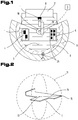
- FIG. 2 An example of a workpiece to be moved is in Fig. 2 shown.
- an envelope ball 11 which is defined by the determined workpiece center of gravity 13 and a radius 14 to the farthest point 15 of the workpiece 1.
- This envelope ball 11 is used to estimate the spatial dimension of a workpiece 1 flying around when the workpiece is lost, for example a sheet metal part which can rotate about its center of gravity 13 of the workpiece until its impact at the point of impact 18.
- Fig. 3 shows a situation in which the workpiece 1, which is held by a holding tool 16, continuously a calculation of a possible impact point 18 at workpiece loss by the holding tool 16.
- the impact point 18 is spaced from the holding tool 16 by the trajectory 19 in the horizontal or vertical direction.
- the trajectory 19 can be approximated by the calculation of a parabola.
- Fig. 3 It can be seen that the object of the invention is to carry out the movement of the workpiece 1 in such a way that, in the event of a possible workpiece loss, the point of impact 18 always takes place within the danger zone 8. Therefore, a dynamic calculation and control of the trajectory 22 of the holding tool 16 takes place simultaneously with the calculation of the point of impingement 18.
- the trajectory 22 can be continuously corrected such that the eventual impingement point 18 of the workpiece 1 takes place within the danger zone 8.
- the movement of the workpiece 1 or the holding tool 16 is in Fig. 3 schematically indicated by movement arrows.
- the workpiece 1 is guided on its movement path 22 by a holding tool 16 designed as a suction gripper 35.
- Fig. 4 is shown a further and possibly separate embodiment of the inventive method. To avoid unnecessary repetition, the detailed description of the Fig. 1 to 3 or 5 to 7 and referenced. As in Fig. 4 illustrated, it may be advantageous to superimpose a compensation movement 33 of the movement path 22 of the holding tool 16. From the synopsis with Fig. 5 It can be seen that, with momentary acceleration of the workpiece 1 in space, an inertial force 31 and the force of gravity 30 act on the workpiece 1. From these two forces results in a resultant force 32, which acts on the center of gravity 13 of the workpiece 1. As in Fig. 4 can be seen on the ordinate motion data 29, as some speed (v) and acceleration (a) can be seen.
- Fig. 4 exemplifies a typical movement of a holding tool 16.
- a compensating movement 33 in the form of a translational and / or rotational movement of the holding tool 16 is performed to compensate for the resultant force 32 and the movement path 22 is superimposed.
- the nominal speed is reached, as in position C of Fig. 4
- a braking process which is shown as negative acceleration
- the negative acceleration is introduced in Figure d and accompanied by a movement of the movement 22 superimposed compensation movement 33.
- This is in particular from point E in Fig. 4 seen.
- the compensation movement 33 takes place in such a way that the resulting force 32 of the workpiece acts normally on the workpiece surface 12 contacted by the holding tool 16.
- the compensating movement 33 it may be advantageous for the compensating movement 33 to be carried out in such a way that the resultant force 32 acts in the direction of a translation and / or rotation center of the holding tool 16.
- Fig. 5 is a schematic representation of the, known in the art per se, force relationship between gravity 30 and inertial force 31 and the resulting force 32 can be seen.
- the holding tool 16 is formed as a suction pad 35
- the resulting force 32 acts both normal on the contacting workpiece surface 12 and in the direction of a translation and / or rotation center of the holding tool 16 and the manipulator 10.
- the in Fig. 5 illustrated situation is analogous to the invention and related embodiments of the Fig. 1 to 4 as well as 6 to 7 to transfer. It is also out Fig. 5 easily deducible that the resulting force 32 may be directed in the direction of a translation and / or rotation center of the holding tool (16), for example, a tilting of the holding tool 16.
- the holding tool 16 is designed as a multipart suction gripper 35 or as a gripper gripper.
- the holding tool 16 points in Fig. 6a in this way several, in the specific case 3, Partialgreifer 17 on.
- These partial grippers 17 each exert partial holding forces 21 on the workpiece surface 12 of the workpiece 1 at the respective partial contact positions 24.
- the sum of the partial holding forces 21 is the holding force 20.
- the workpiece center of gravity 13 is removed from the common contact position 23 and the partial contact positions 24 of the holding tool 16.
- the resulting force 32 a tilting moment 25 on the workpiece 1 at the for Workpiece center of gravity 13 closest Partialcardposition 24 exercises.
- the different height of the partial holding forces 21 is schematically indicated by arrows of different lengths.
- the height of the partial holding forces 21 increases with increasing distance of the respective partial contact positions from the center of gravity 13 of the workpiece.
- the partial contact positions 24 and the partial grippers 17 are arranged at a predeterminable distance 34 separated from each other.
- the embodiment shown by means of suction pads 35 can be carried out analogously by means of magnetic grippers.
- Fig. 6b Another possibility of performing a compensation movement 33 is shown.
- the compensation movement 33 is effected by a translation and / or rotational movement of the holding tool 16 about the workpiece center of gravity 13.
- the resulting force 32 can act in such a way that a tilting moment 25 occurs on the holding tool 16.
- the introduced compensating movement 33 is executed around the center of gravity 13 of the workpiece.
- using a forceps gripper or plate gripper results in the resultant force 32 acting toward a translational and / or rotational center of the holding tool 16.
- a suction gripper 35 analogously to a suction gripper 35, the application of the holding force 20 from two sides onto the workpiece 1 at respective partial contact positions 24 can be seen.
- Fig. 7 For example, an embodiment is shown in which the holding tool 16 is designed as a forceps gripper. In this case, the application of the holding force 20 takes place on two opposite workpiece surfaces 12 of the workpiece 1.
- an optical sensor element 27 is formed on the holding tool 16.
- the sensor element 27 can be used to detect the workpiece geometry of the workpiece 1 and to provide the acquired measurement data for determining the workpiece center of gravity 13 of the system controller 3.
- the formation of two motion sensors 36 which make a detection of a relative displacement 37 of the workpiece 1 possible.
- a motion sensor 36 is already sufficient.
- the originally assumed position of the workpiece 1 is shown by dashed lines.
- the detected relative displacement of the workpiece 1 relative to the holding tool 16 is used for the dynamic calculation of a possible impact point 18 Within the danger zone 8 by the changed position and / or movement speed of the workpiece 1.
- countermeasures such as increasing the holding force 20 or a reduction in the speed of the holding tool 16 along its trajectory 22 are possible.
- compensation movements 33 of the holding tool 16 by an overlay of the movement path 22 is possible. This is made possible by the knowledge of the relative displacement 37, respectively a recorded Relativverschiebungs economically and the holding force 20, the calculation of the current coefficient of friction between the holding tool 16 and the workpiece 1.
- An arrangement of one or more motion sensors 36 is also conceivable on a holding tool 16 designed as a suction gripper 35 or magnetic gripper.
- the present invention also relates to the use of an inertial sensor 38 for the continuous acquisition of spatial movement data 29 of the holding tool 16. This movement data 29 can be used for the dynamic calculation of the impact point 18 and / or the movement path 22 of the holding tool 16.
- the inertial sensor 38 is connected to the system controller 3.
- An exemplary arrangement of such an inertial sensor 38 is shown in FIG Fig. 4 schematically indicated within the holding tool 16. In this way, a dynamic detection of the actual movement data of the holding tool 16, respectively of the workpiece 1, can be performed and adjusted with the calculated movement data 29 of the holding tool 16.
- the positioning of the inertial sensor 38 can be carried out by the skilled person at other locations of the holding tool 16 and / or the manipulator 10 and is thus compatible with all previously discussed embodiments.
- the calculation of one or more computers can be performed in redundancy and made available to the plant controller 3. It is likewise possible that one of the system control 3 hierarchically superordinate safety control continuously performs an adjustment of the redundantly calculated impingement points 18 and / or the movement path 22 of the holding tool 16.
- FIG. 1 Another aspect of the invention relates to the use of a preferred laser-optical environmental sensor 28, which, for example, in Fig. 1 is shown schematically.
- the environment sensor 28 continuously detects the security area 9 and is preferably as a 3D sensor educated.
- Such an environmental sensor 28 may, for example, on the bending machine 2 but also, as in Fig. 1 can be seen, arranged on the manipulator 10.
- Such an environmental sensor 28 serves to detect movable collision objects 26 and / or their movement speed and / or direction.
- These measured variables can be included by the system controller 3 in the calculation of the eventual impact point 18 and / or the movement path 22 of the holding tool 16. This permits dynamic control of the movement path 22 as one of the possible counterreactions of the system control 3 when a movable collision object 26 enters within the security area 9 or even the danger area 8 and the processing space 7.
Landscapes
- Engineering & Computer Science (AREA)
- Robotics (AREA)
- Mechanical Engineering (AREA)
- Physics & Mathematics (AREA)
- General Physics & Mathematics (AREA)
- Automation & Control Theory (AREA)
- Human Computer Interaction (AREA)
- Manufacturing & Machinery (AREA)
- Manipulator (AREA)
Applications Claiming Priority (1)
| Application Number | Priority Date | Filing Date | Title |
|---|---|---|---|
| ATA50307/2018A AT521085B1 (de) | 2018-04-11 | 2018-04-11 | Verfahren zur Bewegungssteuerung eines Werkstücks |
Publications (2)
| Publication Number | Publication Date |
|---|---|
| EP3552777A1 true EP3552777A1 (fr) | 2019-10-16 |
| EP3552777B1 EP3552777B1 (fr) | 2021-03-17 |
Family
ID=66102931
Family Applications (1)
| Application Number | Title | Priority Date | Filing Date |
|---|---|---|---|
| EP19168071.9A Active EP3552777B1 (fr) | 2018-04-11 | 2019-04-09 | Procédé de commande du mouvement d'un manipulateur tenant une pièce à usiner |
Country Status (2)
| Country | Link |
|---|---|
| EP (1) | EP3552777B1 (fr) |
| AT (1) | AT521085B1 (fr) |
Citations (5)
| Publication number | Priority date | Publication date | Assignee | Title |
|---|---|---|---|---|
| DE102010052396A1 (de) * | 2010-11-24 | 2012-05-24 | Kuka Roboter Gmbh | Verfahren und Vorrichtung zum Steuern einer Peripheriekomponente eines Robotersystems |
| DE10361132B4 (de) | 2003-06-18 | 2013-02-28 | Elan Schaltelemente Gmbh & Co. Kg | Verfahren zur Überwachung der Bewegung eines sich in mehreren Freiheitsgraden bewegenden Gefahr bringenden Objektes eines Handhabungsgerätes, wie Handhabungsmasse und/oder bewegliche Masse |
| WO2013026497A1 (fr) * | 2011-09-09 | 2013-02-28 | Abb Technology Ag | Dimensionnement d'une borne pour une cellule robotisée |
| EP2741065A1 (fr) * | 2011-08-03 | 2014-06-11 | Kabushiki Kaisha Yaskawa Denki | Détecteur de déplacement positionnel, main de robot et système de robot |
| EP3189947A1 (fr) * | 2016-01-07 | 2017-07-12 | Sick Ag | Procede de configuration et de fonctionnement d'une cellule de travail automatisee surveillee et dispositif de configuration |
Family Cites Families (2)
| Publication number | Priority date | Publication date | Assignee | Title |
|---|---|---|---|---|
| DE102007037077B4 (de) * | 2007-08-06 | 2019-02-21 | Kuka Roboter Gmbh | Verfahren zur Einhaltung von Arbeitsraumgrenzen eines Arbeitsmittels eines Roboters |
| DE102016007520A1 (de) * | 2016-06-20 | 2017-12-21 | Kuka Roboter Gmbh | Überwachung einer Roboteranordnung |
-
2018
- 2018-04-11 AT ATA50307/2018A patent/AT521085B1/de active
-
2019
- 2019-04-09 EP EP19168071.9A patent/EP3552777B1/fr active Active
Patent Citations (5)
| Publication number | Priority date | Publication date | Assignee | Title |
|---|---|---|---|---|
| DE10361132B4 (de) | 2003-06-18 | 2013-02-28 | Elan Schaltelemente Gmbh & Co. Kg | Verfahren zur Überwachung der Bewegung eines sich in mehreren Freiheitsgraden bewegenden Gefahr bringenden Objektes eines Handhabungsgerätes, wie Handhabungsmasse und/oder bewegliche Masse |
| DE102010052396A1 (de) * | 2010-11-24 | 2012-05-24 | Kuka Roboter Gmbh | Verfahren und Vorrichtung zum Steuern einer Peripheriekomponente eines Robotersystems |
| EP2741065A1 (fr) * | 2011-08-03 | 2014-06-11 | Kabushiki Kaisha Yaskawa Denki | Détecteur de déplacement positionnel, main de robot et système de robot |
| WO2013026497A1 (fr) * | 2011-09-09 | 2013-02-28 | Abb Technology Ag | Dimensionnement d'une borne pour une cellule robotisée |
| EP3189947A1 (fr) * | 2016-01-07 | 2017-07-12 | Sick Ag | Procede de configuration et de fonctionnement d'une cellule de travail automatisee surveillee et dispositif de configuration |
Also Published As
| Publication number | Publication date |
|---|---|
| AT521085A1 (de) | 2019-10-15 |
| EP3552777B1 (fr) | 2021-03-17 |
| AT521085B1 (de) | 2020-02-15 |
Similar Documents
| Publication | Publication Date | Title |
|---|---|---|
| EP2698234B1 (fr) | Dispositif et procédé de prélèvement automatisée de pièces agencées dans un récipient | |
| EP2073084B1 (fr) | Procédé et dispositif de commande d'un manipulateur de robot | |
| EP3774198B1 (fr) | Dispositif et procédé servant à surveiller des déplacements relatifs | |
| EP2563553B1 (fr) | Procédé et moyen de commande pour commander un robot | |
| DE102013106819B4 (de) | Verfahren zum robotergestützten Stapeln von Gegenständen | |
| DE102007037077B4 (de) | Verfahren zur Einhaltung von Arbeitsraumgrenzen eines Arbeitsmittels eines Roboters | |
| DE102007059480B4 (de) | Verfahren und Vorrichtung zur Posenüberwachung eines Manipulators | |
| DE102007037078B4 (de) | Verfahren zur Einhaltung von Arbeitsraumgrenzen eines Arbeitsmittels eines Roboters | |
| EP3782773A1 (fr) | Outil pour un robot collaborant, robot pourvu d'outil fixé audit robot ainsi que procédé de protection contre la collision | |
| DE202013104860U1 (de) | Arbeitsvorrichtung | |
| EP3528996B1 (fr) | Procédé permettant de prévoir une tendance au basculement d'une partie de pièce découpée et machine d'usinage pour l'usinage par découpage d'une pièce en forme de plaque | |
| EP3148751B1 (fr) | Poste de travail pour collaboration homme-robot équipé d'un dispositif de montage | |
| DE102012007242A1 (de) | Vorrichtung und Verfahren zur sicheren Mensch-Roboter-Kooperation | |
| DE102007037404B4 (de) | Verfahren zum maschinellen Verarbeiten und/oder Transfer von Bauteilen | |
| EP3744436A1 (fr) | Presse à redresser et procédé de redressage par cintrage des pièces allongées | |
| EP4098590A1 (fr) | Procédé et système de préparation de commandes des marchandises de détail | |
| EP3359302A1 (fr) | Procédé et dispositif permettant de masquer des trous de fixation dans des jantes | |
| WO2020011337A1 (fr) | Dispositif de travail muni d'un robot monté sous table | |
| EP3552777B1 (fr) | Procédé de commande du mouvement d'un manipulateur tenant une pièce à usiner | |
| EP3981554A1 (fr) | Dispositif de manutention pourvu de système adaptatif de protection contre les collisions | |
| EP3429797B1 (fr) | Station de travail au laser commandée à distance and methode pour utiliser une station de travail au laser commandée à distance | |
| DE102013022533B3 (de) | Verfahren zum robotergestützten Stapeln von Gegenständen | |
| EP3427904B1 (fr) | Système comprenant un manipulateur et un dispositif de limitation d'un espace de travail | |
| EP4419298A1 (fr) | Système et procédé pour sécuriser en trois dimensions un environnement de manipulation de charge de cinématique de manipulation de charge dans un environnement de travail changeant | |
| EP3244981A1 (fr) | Moyen de déplacement avec un système robotique |
Legal Events
| Date | Code | Title | Description |
|---|---|---|---|
| PUAI | Public reference made under article 153(3) epc to a published international application that has entered the european phase |
Free format text: ORIGINAL CODE: 0009012 |
|
| STAA | Information on the status of an ep patent application or granted ep patent |
Free format text: STATUS: THE APPLICATION HAS BEEN PUBLISHED |
|
| AK | Designated contracting states |
Kind code of ref document: A1 Designated state(s): AL AT BE BG CH CY CZ DE DK EE ES FI FR GB GR HR HU IE IS IT LI LT LU LV MC MK MT NL NO PL PT RO RS SE SI SK SM TR |
|
| AX | Request for extension of the european patent |
Extension state: BA ME |
|
| STAA | Information on the status of an ep patent application or granted ep patent |
Free format text: STATUS: REQUEST FOR EXAMINATION WAS MADE |
|
| 17P | Request for examination filed |
Effective date: 20200410 |
|
| RBV | Designated contracting states (corrected) |
Designated state(s): AL AT BE BG CH CY CZ DE DK EE ES FI FR GB GR HR HU IE IS IT LI LT LU LV MC MK MT NL NO PL PT RO RS SE SI SK SM TR |
|
| RIC1 | Information provided on ipc code assigned before grant |
Ipc: B25J 9/16 20060101AFI20200806BHEP |
|
| GRAP | Despatch of communication of intention to grant a patent |
Free format text: ORIGINAL CODE: EPIDOSNIGR1 |
|
| STAA | Information on the status of an ep patent application or granted ep patent |
Free format text: STATUS: GRANT OF PATENT IS INTENDED |
|
| INTG | Intention to grant announced |
Effective date: 20201016 |
|
| GRAS | Grant fee paid |
Free format text: ORIGINAL CODE: EPIDOSNIGR3 |
|
| GRAA | (expected) grant |
Free format text: ORIGINAL CODE: 0009210 |
|
| STAA | Information on the status of an ep patent application or granted ep patent |
Free format text: STATUS: THE PATENT HAS BEEN GRANTED |
|
| AK | Designated contracting states |
Kind code of ref document: B1 Designated state(s): AL AT BE BG CH CY CZ DE DK EE ES FI FR GB GR HR HU IE IS IT LI LT LU LV MC MK MT NL NO PL PT RO RS SE SI SK SM TR |
|
| REG | Reference to a national code |
Ref country code: GB Ref legal event code: FG4D Free format text: NOT ENGLISH |
|
| REG | Reference to a national code |
Ref country code: CH Ref legal event code: EP |
|
| REG | Reference to a national code |
Ref country code: DE Ref legal event code: R096 Ref document number: 502019000989 Country of ref document: DE |
|
| REG | Reference to a national code |
Ref country code: IE Ref legal event code: FG4D Free format text: LANGUAGE OF EP DOCUMENT: GERMAN |
|
| REG | Reference to a national code |
Ref country code: AT Ref legal event code: REF Ref document number: 1371814 Country of ref document: AT Kind code of ref document: T Effective date: 20210415 |
|
| REG | Reference to a national code |
Ref country code: LT Ref legal event code: MG9D |
|
| PG25 | Lapsed in a contracting state [announced via postgrant information from national office to epo] |
Ref country code: NO Free format text: LAPSE BECAUSE OF FAILURE TO SUBMIT A TRANSLATION OF THE DESCRIPTION OR TO PAY THE FEE WITHIN THE PRESCRIBED TIME-LIMIT Effective date: 20210617 Ref country code: BG Free format text: LAPSE BECAUSE OF FAILURE TO SUBMIT A TRANSLATION OF THE DESCRIPTION OR TO PAY THE FEE WITHIN THE PRESCRIBED TIME-LIMIT Effective date: 20210617 Ref country code: GR Free format text: LAPSE BECAUSE OF FAILURE TO SUBMIT A TRANSLATION OF THE DESCRIPTION OR TO PAY THE FEE WITHIN THE PRESCRIBED TIME-LIMIT Effective date: 20210618 Ref country code: FI Free format text: LAPSE BECAUSE OF FAILURE TO SUBMIT A TRANSLATION OF THE DESCRIPTION OR TO PAY THE FEE WITHIN THE PRESCRIBED TIME-LIMIT Effective date: 20210317 Ref country code: HR Free format text: LAPSE BECAUSE OF FAILURE TO SUBMIT A TRANSLATION OF THE DESCRIPTION OR TO PAY THE FEE WITHIN THE PRESCRIBED TIME-LIMIT Effective date: 20210317 |
|
| REG | Reference to a national code |
Ref country code: NL Ref legal event code: MP Effective date: 20210317 |
|
| PG25 | Lapsed in a contracting state [announced via postgrant information from national office to epo] |
Ref country code: LV Free format text: LAPSE BECAUSE OF FAILURE TO SUBMIT A TRANSLATION OF THE DESCRIPTION OR TO PAY THE FEE WITHIN THE PRESCRIBED TIME-LIMIT Effective date: 20210317 Ref country code: RS Free format text: LAPSE BECAUSE OF FAILURE TO SUBMIT A TRANSLATION OF THE DESCRIPTION OR TO PAY THE FEE WITHIN THE PRESCRIBED TIME-LIMIT Effective date: 20210317 Ref country code: SE Free format text: LAPSE BECAUSE OF FAILURE TO SUBMIT A TRANSLATION OF THE DESCRIPTION OR TO PAY THE FEE WITHIN THE PRESCRIBED TIME-LIMIT Effective date: 20210317 |
|
| PG25 | Lapsed in a contracting state [announced via postgrant information from national office to epo] |
Ref country code: NL Free format text: LAPSE BECAUSE OF FAILURE TO SUBMIT A TRANSLATION OF THE DESCRIPTION OR TO PAY THE FEE WITHIN THE PRESCRIBED TIME-LIMIT Effective date: 20210317 |
|
| PG25 | Lapsed in a contracting state [announced via postgrant information from national office to epo] |
Ref country code: SM Free format text: LAPSE BECAUSE OF FAILURE TO SUBMIT A TRANSLATION OF THE DESCRIPTION OR TO PAY THE FEE WITHIN THE PRESCRIBED TIME-LIMIT Effective date: 20210317 Ref country code: LT Free format text: LAPSE BECAUSE OF FAILURE TO SUBMIT A TRANSLATION OF THE DESCRIPTION OR TO PAY THE FEE WITHIN THE PRESCRIBED TIME-LIMIT Effective date: 20210317 Ref country code: EE Free format text: LAPSE BECAUSE OF FAILURE TO SUBMIT A TRANSLATION OF THE DESCRIPTION OR TO PAY THE FEE WITHIN THE PRESCRIBED TIME-LIMIT Effective date: 20210317 Ref country code: CZ Free format text: LAPSE BECAUSE OF FAILURE TO SUBMIT A TRANSLATION OF THE DESCRIPTION OR TO PAY THE FEE WITHIN THE PRESCRIBED TIME-LIMIT Effective date: 20210317 |
|
| PG25 | Lapsed in a contracting state [announced via postgrant information from national office to epo] |
Ref country code: IS Free format text: LAPSE BECAUSE OF FAILURE TO SUBMIT A TRANSLATION OF THE DESCRIPTION OR TO PAY THE FEE WITHIN THE PRESCRIBED TIME-LIMIT Effective date: 20210717 Ref country code: SK Free format text: LAPSE BECAUSE OF FAILURE TO SUBMIT A TRANSLATION OF THE DESCRIPTION OR TO PAY THE FEE WITHIN THE PRESCRIBED TIME-LIMIT Effective date: 20210317 Ref country code: PT Free format text: LAPSE BECAUSE OF FAILURE TO SUBMIT A TRANSLATION OF THE DESCRIPTION OR TO PAY THE FEE WITHIN THE PRESCRIBED TIME-LIMIT Effective date: 20210719 Ref country code: RO Free format text: LAPSE BECAUSE OF FAILURE TO SUBMIT A TRANSLATION OF THE DESCRIPTION OR TO PAY THE FEE WITHIN THE PRESCRIBED TIME-LIMIT Effective date: 20210317 Ref country code: PL Free format text: LAPSE BECAUSE OF FAILURE TO SUBMIT A TRANSLATION OF THE DESCRIPTION OR TO PAY THE FEE WITHIN THE PRESCRIBED TIME-LIMIT Effective date: 20210317 |
|
| REG | Reference to a national code |
Ref country code: DE Ref legal event code: R097 Ref document number: 502019000989 Country of ref document: DE |
|
| PG25 | Lapsed in a contracting state [announced via postgrant information from national office to epo] |
Ref country code: LU Free format text: LAPSE BECAUSE OF NON-PAYMENT OF DUE FEES Effective date: 20210409 |
|
| REG | Reference to a national code |
Ref country code: BE Ref legal event code: MM Effective date: 20210430 |
|
| PLBE | No opposition filed within time limit |
Free format text: ORIGINAL CODE: 0009261 |
|
| STAA | Information on the status of an ep patent application or granted ep patent |
Free format text: STATUS: NO OPPOSITION FILED WITHIN TIME LIMIT |
|
| PG25 | Lapsed in a contracting state [announced via postgrant information from national office to epo] |
Ref country code: MC Free format text: LAPSE BECAUSE OF FAILURE TO SUBMIT A TRANSLATION OF THE DESCRIPTION OR TO PAY THE FEE WITHIN THE PRESCRIBED TIME-LIMIT Effective date: 20210317 Ref country code: DK Free format text: LAPSE BECAUSE OF FAILURE TO SUBMIT A TRANSLATION OF THE DESCRIPTION OR TO PAY THE FEE WITHIN THE PRESCRIBED TIME-LIMIT Effective date: 20210317 Ref country code: AL Free format text: LAPSE BECAUSE OF FAILURE TO SUBMIT A TRANSLATION OF THE DESCRIPTION OR TO PAY THE FEE WITHIN THE PRESCRIBED TIME-LIMIT Effective date: 20210317 Ref country code: ES Free format text: LAPSE BECAUSE OF FAILURE TO SUBMIT A TRANSLATION OF THE DESCRIPTION OR TO PAY THE FEE WITHIN THE PRESCRIBED TIME-LIMIT Effective date: 20210317 |
|
| 26N | No opposition filed |
Effective date: 20211220 |
|
| PG25 | Lapsed in a contracting state [announced via postgrant information from national office to epo] |
Ref country code: SI Free format text: LAPSE BECAUSE OF FAILURE TO SUBMIT A TRANSLATION OF THE DESCRIPTION OR TO PAY THE FEE WITHIN THE PRESCRIBED TIME-LIMIT Effective date: 20210317 |
|
| PG25 | Lapsed in a contracting state [announced via postgrant information from national office to epo] |
Ref country code: IE Free format text: LAPSE BECAUSE OF NON-PAYMENT OF DUE FEES Effective date: 20210409 |
|
| PG25 | Lapsed in a contracting state [announced via postgrant information from national office to epo] |
Ref country code: IS Free format text: LAPSE BECAUSE OF FAILURE TO SUBMIT A TRANSLATION OF THE DESCRIPTION OR TO PAY THE FEE WITHIN THE PRESCRIBED TIME-LIMIT Effective date: 20210717 Ref country code: FR Free format text: LAPSE BECAUSE OF NON-PAYMENT OF DUE FEES Effective date: 20210517 |
|
| PG25 | Lapsed in a contracting state [announced via postgrant information from national office to epo] |
Ref country code: BE Free format text: LAPSE BECAUSE OF NON-PAYMENT OF DUE FEES Effective date: 20210430 |
|
| REG | Reference to a national code |
Ref country code: CH Ref legal event code: PL |
|
| PG25 | Lapsed in a contracting state [announced via postgrant information from national office to epo] |
Ref country code: LI Free format text: LAPSE BECAUSE OF NON-PAYMENT OF DUE FEES Effective date: 20220430 Ref country code: CH Free format text: LAPSE BECAUSE OF NON-PAYMENT OF DUE FEES Effective date: 20220430 |
|
| PG25 | Lapsed in a contracting state [announced via postgrant information from national office to epo] |
Ref country code: CY Free format text: LAPSE BECAUSE OF FAILURE TO SUBMIT A TRANSLATION OF THE DESCRIPTION OR TO PAY THE FEE WITHIN THE PRESCRIBED TIME-LIMIT Effective date: 20210317 |
|
| PG25 | Lapsed in a contracting state [announced via postgrant information from national office to epo] |
Ref country code: HU Free format text: LAPSE BECAUSE OF FAILURE TO SUBMIT A TRANSLATION OF THE DESCRIPTION OR TO PAY THE FEE WITHIN THE PRESCRIBED TIME-LIMIT; INVALID AB INITIO Effective date: 20190409 |
|
| GBPC | Gb: european patent ceased through non-payment of renewal fee |
Effective date: 20230409 |
|
| PG25 | Lapsed in a contracting state [announced via postgrant information from national office to epo] |
Ref country code: GB Free format text: LAPSE BECAUSE OF NON-PAYMENT OF DUE FEES Effective date: 20230409 |
|
| PG25 | Lapsed in a contracting state [announced via postgrant information from national office to epo] |
Ref country code: GB Free format text: LAPSE BECAUSE OF NON-PAYMENT OF DUE FEES Effective date: 20230409 |
|
| PG25 | Lapsed in a contracting state [announced via postgrant information from national office to epo] |
Ref country code: MK Free format text: LAPSE BECAUSE OF FAILURE TO SUBMIT A TRANSLATION OF THE DESCRIPTION OR TO PAY THE FEE WITHIN THE PRESCRIBED TIME-LIMIT Effective date: 20210317 |
|
| PG25 | Lapsed in a contracting state [announced via postgrant information from national office to epo] |
Ref country code: TR Free format text: LAPSE BECAUSE OF FAILURE TO SUBMIT A TRANSLATION OF THE DESCRIPTION OR TO PAY THE FEE WITHIN THE PRESCRIBED TIME-LIMIT Effective date: 20210317 |
|
| PG25 | Lapsed in a contracting state [announced via postgrant information from national office to epo] |
Ref country code: MT Free format text: LAPSE BECAUSE OF FAILURE TO SUBMIT A TRANSLATION OF THE DESCRIPTION OR TO PAY THE FEE WITHIN THE PRESCRIBED TIME-LIMIT Effective date: 20210317 |
|
| PGFP | Annual fee paid to national office [announced via postgrant information from national office to epo] |
Ref country code: IT Payment date: 20250306 Year of fee payment: 7 |
|
| PGFP | Annual fee paid to national office [announced via postgrant information from national office to epo] |
Ref country code: DE Payment date: 20250418 Year of fee payment: 7 |
|
| PGFP | Annual fee paid to national office [announced via postgrant information from national office to epo] |
Ref country code: AT Payment date: 20250423 Year of fee payment: 7 |