EP3552799B1 - Tête d'outil pour extrudeuse de profilés creux - Google Patents
Tête d'outil pour extrudeuse de profilés creux Download PDFInfo
- Publication number
- EP3552799B1 EP3552799B1 EP19163425.2A EP19163425A EP3552799B1 EP 3552799 B1 EP3552799 B1 EP 3552799B1 EP 19163425 A EP19163425 A EP 19163425A EP 3552799 B1 EP3552799 B1 EP 3552799B1
- Authority
- EP
- European Patent Office
- Prior art keywords
- die
- mandrel
- extruder
- tool
- extrusion
- Prior art date
- Legal status (The legal status is an assumption and is not a legal conclusion. Google has not performed a legal analysis and makes no representation as to the accuracy of the status listed.)
- Active
Links
Images


Classifications
-
- B—PERFORMING OPERATIONS; TRANSPORTING
- B29—WORKING OF PLASTICS; WORKING OF SUBSTANCES IN A PLASTIC STATE IN GENERAL
- B29C—SHAPING OR JOINING OF PLASTICS; SHAPING OF MATERIAL IN A PLASTIC STATE, NOT OTHERWISE PROVIDED FOR; AFTER-TREATMENT OF THE SHAPED PRODUCTS, e.g. REPAIRING
- B29C48/00—Extrusion moulding, i.e. expressing the moulding material through a die or nozzle which imparts the desired form; Apparatus therefor
- B29C48/25—Component parts, details or accessories; Auxiliary operations
- B29C48/30—Extrusion nozzles or dies
- B29C48/32—Extrusion nozzles or dies with annular openings, e.g. for forming tubular articles
- B29C48/325—Extrusion nozzles or dies with annular openings, e.g. for forming tubular articles being adjustable, i.e. having adjustable exit sections
- B29C48/327—Extrusion nozzles or dies with annular openings, e.g. for forming tubular articles being adjustable, i.e. having adjustable exit sections with centering means
-
- B—PERFORMING OPERATIONS; TRANSPORTING
- B29—WORKING OF PLASTICS; WORKING OF SUBSTANCES IN A PLASTIC STATE IN GENERAL
- B29C—SHAPING OR JOINING OF PLASTICS; SHAPING OF MATERIAL IN A PLASTIC STATE, NOT OTHERWISE PROVIDED FOR; AFTER-TREATMENT OF THE SHAPED PRODUCTS, e.g. REPAIRING
- B29C48/00—Extrusion moulding, i.e. expressing the moulding material through a die or nozzle which imparts the desired form; Apparatus therefor
- B29C48/03—Extrusion moulding, i.e. expressing the moulding material through a die or nozzle which imparts the desired form; Apparatus therefor characterised by the shape of the extruded material at extrusion
- B29C48/09—Articles with cross-sections having partially or fully enclosed cavities, e.g. pipes or channels
-
- B—PERFORMING OPERATIONS; TRANSPORTING
- B29—WORKING OF PLASTICS; WORKING OF SUBSTANCES IN A PLASTIC STATE IN GENERAL
- B29C—SHAPING OR JOINING OF PLASTICS; SHAPING OF MATERIAL IN A PLASTIC STATE, NOT OTHERWISE PROVIDED FOR; AFTER-TREATMENT OF THE SHAPED PRODUCTS, e.g. REPAIRING
- B29C48/00—Extrusion moulding, i.e. expressing the moulding material through a die or nozzle which imparts the desired form; Apparatus therefor
- B29C48/25—Component parts, details or accessories; Auxiliary operations
- B29C48/256—Exchangeable extruder parts
- B29C48/2562—Mounting or handling of the die
-
- B—PERFORMING OPERATIONS; TRANSPORTING
- B29—WORKING OF PLASTICS; WORKING OF SUBSTANCES IN A PLASTIC STATE IN GENERAL
- B29C—SHAPING OR JOINING OF PLASTICS; SHAPING OF MATERIAL IN A PLASTIC STATE, NOT OTHERWISE PROVIDED FOR; AFTER-TREATMENT OF THE SHAPED PRODUCTS, e.g. REPAIRING
- B29C2948/00—Indexing scheme relating to extrusion moulding
- B29C2948/92—Measuring, controlling or regulating
- B29C2948/92009—Measured parameter
- B29C2948/92114—Dimensions
- B29C2948/92152—Thickness
Definitions
- the invention relates to a tool head for a hollow profile extruder, in particular for a hose extruder.
- the invention further relates to a tool head assembly with such a tool head, an extruder with such a tool head or such a tool head assembly, and an extrusion system with such an extruder.
- a silicone extruder is known from WO 2005/039847 A1 .
- a tool head in the form of a hose extrusion head is known from DE 10 2014 103 521 B3 , the EP 0 075 809 A1 , the EP 2 768 653 B1 and the DE 197 24 692 A1 .
- the FR 2 031 597 A1 discloses the preamble of claim 1 or a tool head for a hollow profile extruder with an extrusion ring channel which is delimited on the outside by a nozzle jacket and on the inside by a mandrel.
- a circumferential distribution of a width of the extrusion ring channel is specified which corresponds to a circumferential distribution of a hollow profile thickness to be extruded, in particular a hose thickness, Achieved via a predeterminable tilting of the tool mandrel relative to the tool ring.
- the result is a defined position of a jacket wall of the hollow profile or hose to be extruded immediately after the tool head, which is advantageous for subsequent guidance or detection of the hose to be extruded, in particular adjacent to the tool head.
- a sensor-based detection of parameters of the hollow profile, in particular parameters of the hose can be simplified and / or improved.
- the extrusion ring channel can follow a heart curve.
- a material flow path for material to be extruded which opens into the extrusion ring channel can be formed in a distributor body which is mounted in the head housing of the tool head.
- At least one cooling channel for cooling the tool head can be arranged in the head housing.
- the tilting joint via which the mandrel carrier can be tilted relative to the tool ring, can have hardened surfaces.
- the tilting joint can have surfaces treated with powder metallurgy. At least one of the surfaces of the tilt joint can have a sliding coating.
- the tool mandrel and / or the tool ring can be designed as replacement parts. To equip the tool head, a set with different pairings of one tool mandrel and one tool ring each or also a set with several tool mandrels / tool rings that are matched to one tool ring / tool mandrel can be included.
- a holder of the tool ring from the axial adjustment housing body against the direction of force of the extrusion pressure makes it possible according to the invention to specify an axial position of the tool ring relative to the tool mandrel by specifying an axial position of the axial adjustment housing body.
- Such an axial position specification enables a setting of a circumferentially averaged width of the annular extrusion channel.
- the axial adjustment housing body can be designed as a centering nut.
- the axial adjustment housing body can be mounted in a receptacle which in turn is mounted on the housing.
- An embodiment according to claim 2 uses a lever action of the mandrel carrier to tilt the tool mandrel.
- a distance between the centering device and the tilt joint can be greater than a distance between the tilt joint and a nozzle outlet of the extrusion ring channel. This distance can, for example, be more than 1.1 times, more than 1.2 times, more than 1.25 times, more than 1.5 times, more than 2 times, more than that 3 times or more than 5 times the distance between the tilt joint and the nozzle opening.
- Centering actuators according to claim 3 have proven useful for setting a tilted position of the tool mandrel.
- the centering actuators can be designed as centering screws.
- the centering device can be carried by a centering ring which in turn is mounted on the head housing.
- the centering ring can be mounted on the distributor body.
- An internal thread on the housing side, which is designed to be complementary to the respective centering actuator, can be part of a centering bushing firmly connected to the head housing.
- a ball joint according to claim 4 has proven itself as a tilting joint for the stepless specification of the tilting position of the tool mandrel relative to the tool ring.
- the ball joint can with a predetermined tolerance between the joint parts, that is to say a joint head or a spherical cap part and a joint socket or a socket part.
- a socket part of the ball joint can be arranged on the housing side.
- the socket part can be implemented in a distributor body mounted in the housing and / or in a centering ring of the centering device or also directly in the head housing.
- a holder for the tool ring according to claim 6 avoids undesirable load peaks when the extrusion pressure is transmitted from the tool ring to the axial adjustment housing body.
- the advantages of a tool assembly according to claim 7 correspond to those which have already been explained above with reference to the tool head. Due to the control / regulating device, it is possible with the tool head assembly to keep certain parameters of the hose to be extruded in a controlled or regulated manner within predetermined tolerance limits.
- a closed-loop control can be implemented.
- the at least one actuator of the centering device can be implemented in the form of one or more motor-driven centering screws.
- the at least one actuator can be designed as a stepper motor.
- the at least one actuator can interact with a planetary gear.
- the control and regulation device can also interact with an actuator which acts on the axial adjustment housing body to adjust it.
- the axial adjustment housing body is designed as a centering nut.
- the actuator can then cause a rotation of the centering nut.
- the actuator can be designed as a stepper motor and can act on the centering nut via a planetary gear.
- the sensor can be a sensor for measuring a wall thickness of the hose extruded with the tool head.
- the sensor can be designed as a radiometric sensor, for example as an X-ray sensor. Alternatively or additionally, the sensor can be designed as a microwave or ultrasonic sensor.
- the control / regulating device can additionally detect a plurality of further input variables of the extruder and / or the extrusion system and pass on actuating signals to drive units or actuators of the extruder and the extrusion system to control and / or regulate corresponding parameters. In particular, maintaining a constant feed pressure has proven to be particularly advantageous for the extrusion result.
- the input variables can be an actual charging temperature of the extrusion material or also a discharge pressure of the extruded mass in the area of the tool head or also a discharge temperature.
- the loading device of the extrusion plant can be a loading device with a loading screw and a feed hopper.
- the loading device can also be constructed differently.
- the extruder can be a silicone extruder and / or an extruder for a thermoplastic material or for a polyolefin material.
- An extruded hollow profile or an extruded tube can be used in particular in medical technology.
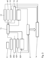
- An extrusion plant 1 has an extruder 2 and a charging device 3 for charging the extruder 2 with mass to be extruded.
- the mass to be extruded can be silicone.
- the mass to be extruded can also be a different material, for example a thermoplastic.
- the extruder 2 is designed as a hollow profile extruder and, in the illustrated embodiment, as a tube extruder.
- the charging device 3 has a feed box 4 at the top, which opens into a feed hopper 5 at the bottom. The latter in turn opens into a bottom loading opening 6.
- the bulk loading opening 6 is in fluid connection with a feed zone of the extruder 2 via a feed channel 7.
- the Figure 1 shows an embodiment of the charging device with an upright feed hopper 5.
- An alternative, not shown, embodiment has an inclined feed hopper 5.
- the extruder 2 can be designed as a single-screw or as a twin-screw extruder.
- Feed device 3 Part of the feed device 3 is a feed screw, not shown in detail.
- the latter is mounted axially and radially on a frame housing 8 of the extrusion system 1.
- the feed hopper 5 is designed to be rotatable.
- the feed hopper 5 is again mounted axially and radially relative to the frame housing 8 near the charging opening 6.
- the two rotary drives for the feed screw on the one hand and the feed hopper 5 on the other hand are designed to be independent of one another.
- the rotary drives or the common drive for the feeding screw and the feed hopper 5 can be designed as a synchronous motor.
- the charging device 3 is cooled with cooling water, which can be circulated.
- the Figure 1 shows the charging device 3 in a charging position, i.e. in an operating position for feeding the mass to be extruded via the feed box 4, the feed hopper 5, the feed opening 6 and the feed channel 7 to the feed zone of the extruder 2.
- the loading device 3 can be in a relative to the loading position of the Figure 1
- the cleaning or maintenance position swiveled out about a vertical swivel axis and linearly displaced downwards along this swivel axis can be displaced.
- This pivoted cleaning or maintenance position is not shown in the drawing. Both the pivoting and the displacement movement are guided in a displacement frame section 9 of the frame housing 8.
- a flange connection 10 between two sections of the loading channel 7 is released.
- the extrusion plant 1 has a central control 11 with an operating terminal 12.
- the control 11 is in signal connection with the two rotary drives of the feed screw and the feed hopper 5.
- a loading pressure sensor BDS (cf. Fig. 3 ) arranged in a transition area between the loading device 3 and the extruder 2, i.e. in the area of the loading channel 7, there is a loading pressure sensor BDS (cf. Fig. 3 ) arranged.
- the latter is used for Measuring an actual feed pressure of the mass to be extruded.
- the pressure sensor BDS is arranged in such a way that a sensor signal from the pressure sensor BDS for regulating a pressure of the mass to be extruded can be generated directly in front of the feed zone of the extruder 2.
- the pressure sensor BDS can be arranged directly adjacent to the feed zone.
- Part of the controller 11 is one in the Figure 1 schematically indicated control unit 13 (cf. also the signal processing scheme according to FIG Fig. 3 ), which is in signal connection with the loading pressure sensor BDS and the loading drive device, i.e. the loading rotary drive BDA and / or the feed hopper rotary drive ADA.
- the control unit 13 is used to specify a setpoint loading pressure and to forward a control signal to the loading drive unit BDA as a function of a determined difference between the setpoint loading pressure and the actual loading pressure.
- a charging temperature sensor BTS for measuring an actual charging temperature of the mass to be extruded is also arranged in the coating channel 7.
- the loading temperature sensor BTS is in signal connection with the control unit 13.
- the extrusion system 1 has in a tool head 14 of the extruder 2, which in the Figure 2 Shown in greater detail and arranged in the area of a discharge zone of the extruder 2, a tool head pressure sensor 15. The latter is used to measure an actual discharge pressure of the mass to be extruded.
- the control unit 13 is in signal connection with the tool head pressure sensor 15 and an extruder drive unit 16.
- the extruder drive unit 16 is used to drive at least an extruder screw that runs in a housing cylinder 17 of the extruder 2.
- the control unit 13 is also used to specify a target discharge pressure of the mass to be extruded and to forward a corresponding control signal to the extruder drive unit 16 depending on a determined difference between the target discharge pressure and the actual discharge pressure.
- the extrusion system 1 also has a discharge temperature sensor 18, which is also arranged in the tool head 14 of the extruder 2.
- the discharge temperature sensor 18 is used to measure an actual discharge temperature of the mass to be extruded.
- the discharge temperature sensor 18 is in signal connection with the control unit 13.
- Fig. 2 shows details of the tool head 14 in an axial longitudinal section.
- the tool head 14 has a head housing 19 in which a material or mass flow path 20 is specified, which opens out into an extrusion ring channel 21 on the outlet nozzle side.
- the extrusion ring channel 21 is delimited on the inside by a tool mandrel 22 and is delimited on the outside by a tool ring 23.
- a longitudinal axis LWK of the tool head 14 can run in alignment, parallel or, as in the embodiment described, perpendicular thereto.
- the longitudinal axis LWK of the tool head 14 thus runs radially to the longitudinal axis LE of the extruder 2.
- a material inlet 24 from the extruder 2 here runs through a jacket wall 25 of the head housing 19, as in FIG Fig. 2 indicated schematically.
- This material inlet 24 forms an inlet channel which is in fluid connection with the extrusion ring channel 21 via a distribution channel 26 and the material flow path 20.
- the tool mandrel 22 is carried and held by a mandrel carrier 27 on the housing side.
- the mandrel carrier 27 has a dome-shaped mandrel articulation section 28 and a tilting rod section 29.
- a centering device 30 is arranged, which is described in more detail below is explained.
- the mandrel carrier 27 is mounted so that it can be tilted by two degrees of freedom relative to the tool ring 23 via a tilting joint.
- the tilting joint is formed on the one hand by the mandrel joint section 28 as a spherical part and a socket section 31 of a distributor body 32, which is designed to be complementary thereto, as a socket part.
- the distributor body 32 is mounted fixed to the housing in the head housing 19.
- the tilting joint 28, 31 is designed as a ball joint.
- a predetermined component clearance for example in the range between 50 ⁇ m and 200 ⁇ m, can be implemented between the two joint parts of the ball joint 28, 31, that is to say the mandrel joint section 28 and the distributor socket section 31.
- the cap part of the ball joint 28, 31, that is to say the mandrel joint section can be integrally formed on the tilting rod section 29 of the mandrel carrier 27.
- the tilting joint 28, 31 can be hardened Have surfaces on the mandrel articulation section 28 and / or on the distributor socket section 31. These can be surfaces treated with powder metallurgy.
- the sections 28, 31 of the tilting joint can have a sliding coating.
- the tiltability of the mandrel carrier 27 relative to the tool ring 23 via the tilting joint 28, 31 is such that, depending on the tilted position of the mandrel carrier 27, a circumferential distribution of a width RK of the extrusion ring channel 21 between a nozzle-side section of the tool mandrel 22 and the tool ring 23 can be specified.
- a circumferential distribution of a width RK of the extrusion ring channel 21 between a nozzle-side section of the tool mandrel 22 and the tool ring 23 can be specified.
- a relative position of a hose jacket wall 33, which in the Fig. 2 is indicated by dashed lines, remains independent of a tilted position of the tilting joint 28, 31.
- the material flow path 20 between the material inlet 24 and the extrusion ring channel 21 can follow a heart curve.
- a description of this can be found by the person skilled in the art, for example, in the textbook “ Handbuch Urformen - Edition Handbuch der Vietnamesestechnik "(second edition, 2003, Carl Hanser Verlag, publisher Bührig-Polaczek et al.).
- Cooling fluid can generally be a temperature control fluid for controlling the temperature of the tool head 14, that is to say for keeping the tool head 14 at a predetermined temperature.
- the tool mandrel 22 and / or the tool ring 23 can be designed as replacement parts.
- different pairings of one type of tool mandrel 22 and one type of tool ring 23 can be specified.
- the scope of delivery of the tool head 14 can accordingly include a set of several such pairings of tool mandrel / tool ring.
- the tool mandrel 22 can be detachably connected to the mandrel carrier 27, for example via a screw connection.
- the tool ring 23 can be held by an axial adjustment housing body 35 counter to an extrusion direction ER.
- the latter can be screwed to an adjustment section 37 of the head housing 19 via a thread 36.
- the axial adjustment housing body 35 can be designed as a centering nut.
- the adjustment section 37 represents a receptacle for the axial adjustment housing body 35.
- the tool ring 23 is received in a floating manner in the axial adjustment housing body 35.
- the centering device 30 has a plurality of centering actuators in the form of centering screws 38, of which in the Figure 2 two centering screws 38 are shown schematically.
- the centering screws 38 run radially to the longitudinal axis LWK of the tool head 14 and thus, in good approximation, also radially to the longitudinal axis of the mandrel carrier 27.
- the centering screws 38 are mounted on the head housing 19 in a manner not shown.
- the centering screws 38 can be screwed into ring sections 39 of a centering ring, otherwise not shown, which in turn is mounted on the head housing 19 and / or on the distributor body 32.
- An internal thread of the ring section 39 can also be part of a centering bushing which is separate from the head housing 19 and firmly connected to it and which is shown in FIG Fig. 2 at 40 is indicated.
- Free ends 41 of the centering screws 38 rest on a peripheral wall 42 of a centering head 43 of the mandrel carrier 27.
- the centering head 43 is firmly connected to the tilting rod section 29 of the mandrel carrier 27 and can be an integral part of the tilting rod section 29.
- the respective tilted position that is to say the position of the longitudinal axis of the mandrel carrier 27 relative to the longitudinal axis of the entire tool head 14, can be specified via a screw-in depth of the centering screws 38 in the respective centering bushes 40.
- centering screws 38 shown in the circumferential direction can be arranged, in particular, evenly distributed around the longitudinal axis LWK of the tool head 14, so that in particular a stepless specification of a tilting position of the mandrel carrier 27 in the two degrees of tilting freedom is possible.
- the centering screws 38 can be motor-driven with the aid of corresponding, respectively assigned rotary drives 44.
- a tool head assembly 45 of which the tool head 14 is a component, can also include at least one sensor 46 for measuring a wall thickness of the hose extruded with the tool head.
- the wall thickness sensor 46 can be designed as a radiometric sensor, for example as an X-ray sensor.
- Both the rotary drives 44, which then represent actuators of the centering device 30, and the at least one wall thickness sensor 46 are in signal connection with the controller 11 and the regulating unit 13 (see also FIG Fig. 3 ).
- An adjustment of the mean width of the extrusion ring channel 21 can in particular take place continuously with an accuracy in the range of 1/100 millimeter.
- a wall thickness of a tube to be extruded can be set to a predetermined value with a tolerance that is less than 100 ⁇ m, which can also be less than 50 ⁇ m, which can be less than 30 ⁇ m, which can be less than 20 ⁇ m and also can be less than 10 ⁇ m.
- a temperature in the at least one temperature zone in the conveying path of the extrudate mass of the extrusion system 1 can be specified via a temperature control medium.
- the feed hopper 5 and / or the feed channel 7 and / or the extruder 2, optionally in zones, can be actively temperature-controlled and in particular cooled with a temperature control medium, for example with water.
- Another control variable that can be kept constant by comparing a measured actual value with a predetermined setpoint value via the control unit 13 is a material throughput in the conveying path of the extrusion system 1. This throughput can be measured at various points along the entire conveying path between the loading device 3 and the tool head 14 become.
- the mass to be extruded is first fed into the charging device 3.
- the mass to be extruded is then conveyed through the charging device 3 and the extruder 2.
- the extrudate produced is then discharged from the extruder 2 in the form of a profile or tube via the tool head 14.
- the extrusion plant 1 is operating in a regulated manner, the mass is conveyed in a regulated manner through the charging device 3 and the extruder 2 using the control signals from the control unit 13.
- control signals from the control unit 13 can be transferred to the feed hopper rotary drive ADA and / or to the screw rotary drive BDA and / or to the extruder drive unit 16 and / or to control components of the tool head 24, how, for example, the actuators 44 of the centering device 30 act.
- a rotational speed of the feed hopper 5 a rotational speed of the feed screw and / or a screw speed of the extruder 2 can be specified or manipulated variables of adjustable components of the tool head 24 such as the circumferential distribution and / or the mean value of the width RK of the extrusion Ring channel 21.
- Drives of the extrusion system 1, in particular the rotary drives 10, 15, 44 and the extrusion drive 16 can be designed to be infinitely variable.
- a tilt position can also be specified in the area of the centering head 43 via linearly driven displaceable reciprocating pistons.
- Drives of the centering device can be designed as electric motors or as hydraulic cylinders.
- the tool head 14 can be cooled in a controlled or regulated manner and in particular depending on the material throughput, the Shore hardness of the material and the respective design of the material flow path 20, on the one hand in the area of the distributor body 32 and on the other hand in the area of the nozzle-side outlet at the extrusion ring channel.
Landscapes
- Engineering & Computer Science (AREA)
- Mechanical Engineering (AREA)
- Manufacturing & Machinery (AREA)
- Extrusion Moulding Of Plastics Or The Like (AREA)
Claims (9)
- Tête d'outil (14) pour une extrudeuse de profilés creux (2),- avec un logement de tête (19),- ayant un canal annulaire d'extrusion (21) qui est délimité vers l'intérieur par un mandrin d'outil (22) et qui est délimité vers l'extérieur par un anneau d'outil (23),- dans laquelle le mandrin d'outil (22) est supporté et retenu par un porte-mandrin (27) du côté du logement,- dans laquelle le porte-mandrin (27) est monté de manière à pouvoir basculer de deux degrés de liberté par rapport à l'anneau d'outil (23) au moyen d'une articulation de basculement (28, 31), de sorte qu'une répartition périphérique d'une largeur du canal annulaire d'extrusion (21) peut être prédéfinie en fonction de la position de basculement du porte-mandrin (27),- avec un dispositif de centrage (30) pour prérégler la position de basculement du porte-mandrin (27),- dans laquelle l'anneau d'outil (23) est tenu contre une direction de force d'une pression d'extrusion par un corps de logement de réglage axial (35),caractérisée en ce que
le corps de logement de réglage axial (35) est conçu de telle sorte qu'une position axiale de l'anneau d'outil (23) par rapport au mandrin d'outil (22) est prédéterminée par le biais d'un préréglage d'une position axiale du corps de logement de réglage axial (35) par rapport au logement de tête (19). - Tête d'outil selon la revendication 1, caractérisée en ce que l'articulation de basculement (28, 31) est disposée sur le côté mandrin du porte-mandrin (27), dans laquelle sur une extrémité libre du porte-mandrin (27), détourné du côté mandrin du porte-mandrin (27), le dispositif de centrage (30) est disposé.
- Tête d'outil selon la revendication 1 ou 2, caractérisée en ce que le dispositif de centrage (30) présente une pluralité d'actionneurs de centrage (38) s'étendant radialement par rapport au porte-mandrin (27), qui sont montés du côté du logement et dont les extrémités libres (41) s'appuient contre le porte-mandrin (27).
- Tête d'outil selon l'une quelconque des revendications 1 à 3, caractérisée en ce que l'articulation de basculement (28, 31) est conçue comme une articulation à rotule.
- Tête d'outil selon la revendication 4, caractérisée en ce qu'une partie calotte (31) de l'articulation à rotule (28, 31) est formée d'un seul tenant sur le porte-mandrin (27).
- Tête d'outil selon l'une quelconque des revendications 1 à 5, caractérisée en ce que l'anneau d'outil (23) est supporté de manière flottante par le corps de logement de réglage axial (35).
- Ensemble de tête d'outil- avec une tête d'outil (14) selon l'une quelconque des revendications 1 à 6,- avec au moins un capteur (46) pour mesurer une épaisseur de paroi d'un tuyau extrudé avec la tête d'outil (14),- avec un dispositif de commande/réglage (11, 13) qui est en liaison de signalisation- avec le capteur (46) et- avec au moins un actionneur (44) du dispositif de centrage (30).
- Extrudeuse (2) comprenant une tête d'outil (14) selon l'une quelconque des revendications 1 à 6, ou comprenant un ensemble d'outils selon la revendication 7.
- Installation d'extrusion (1) avec une extrudeuse selon la revendication 8 et avec un dispositif d'alimentation (3) pour alimenter l'extrudeuse (2) avec de la matière à extruder.
Priority Applications (1)
| Application Number | Priority Date | Filing Date | Title |
|---|---|---|---|
| PL19163425T PL3552799T3 (pl) | 2018-03-28 | 2019-03-18 | Głowica formująca do wytłaczarki wydrążonych profili |
Applications Claiming Priority (1)
| Application Number | Priority Date | Filing Date | Title |
|---|---|---|---|
| DE102018204729.4A DE102018204729A1 (de) | 2018-03-28 | 2018-03-28 | Werkzeugkopf für einen Hohlprofil-Extruder |
Publications (2)
| Publication Number | Publication Date |
|---|---|
| EP3552799A1 EP3552799A1 (fr) | 2019-10-16 |
| EP3552799B1 true EP3552799B1 (fr) | 2021-05-05 |
Family
ID=65818318
Family Applications (1)
| Application Number | Title | Priority Date | Filing Date |
|---|---|---|---|
| EP19163425.2A Active EP3552799B1 (fr) | 2018-03-28 | 2019-03-18 | Tête d'outil pour extrudeuse de profilés creux |
Country Status (6)
| Country | Link |
|---|---|
| US (1) | US20190299514A1 (fr) |
| EP (1) | EP3552799B1 (fr) |
| DE (1) | DE102018204729A1 (fr) |
| DK (1) | DK3552799T3 (fr) |
| HU (1) | HUE055612T2 (fr) |
| PL (1) | PL3552799T3 (fr) |
Families Citing this family (4)
| Publication number | Priority date | Publication date | Assignee | Title |
|---|---|---|---|---|
| DE102020125261B3 (de) | 2020-09-28 | 2021-10-07 | Troester Gmbh & Co. Kg | Extrusionskopf und Verfahren zur Herstellung eines länglichen Hohlkörpers mittels dieses Extrusionskopfs |
| CN114603817B (zh) * | 2022-05-11 | 2022-07-19 | 山东银宝轮胎集团有限公司 | 一种轮胎橡胶用挤出机 |
| CN116181111B (zh) * | 2023-04-26 | 2023-07-04 | 山西建筑工程集团有限公司 | 一种建筑物孔洞封堵用发泡胶喷射装置 |
| CN119388727B (zh) * | 2024-12-31 | 2025-03-07 | 浙江恒益塑料有限公司 | 一种可自动排料的挤出机用模头 |
Family Cites Families (16)
| Publication number | Priority date | Publication date | Assignee | Title |
|---|---|---|---|---|
| US2349178A (en) * | 1941-08-04 | 1944-05-16 | Plax Corp | Method of and apparatus for extruding and blowing organic plastic materials |
| DE1037697B (de) * | 1954-04-30 | 1958-08-28 | Siemens Ag | Strangspritzmaschine zur Herstellung von Schlaeuchen, insbesondere von Isolierstoffhuellen fuer elektrische Leiter |
| US3111714A (en) * | 1962-05-14 | 1963-11-26 | Phillips Petroleum Co | Self-centering extrusion die |
| DE1908933B2 (de) * | 1969-02-22 | 1971-04-29 | Strangpresskopf zum strangpressen eines schlauches | |
| DE6907010U (de) * | 1969-02-22 | 1972-02-03 | Voith Gmbh J M | Ringduese fuer einen extruder. |
| DE3216377A1 (de) | 1981-09-26 | 1983-06-16 | Detlef Dipl.-Ing. 4970 Bad Oeynhausen Gneuss | Vorrichtung zur herstellung von rohren aus plastischen massen |
| US4551087A (en) * | 1984-06-11 | 1985-11-05 | Northern Telecom Limited | Extrusion apparatus |
| CA1221519A (fr) * | 1985-03-08 | 1987-05-12 | Northern Telecom Limited | Garnissage d'un conducteur electrique avec une gaine isolante |
| DE3617652A1 (de) * | 1986-05-26 | 1987-12-03 | Troester Maschf Paul | Extruderanlage zum ummanteln eines strangfoermigen produktes, insbesondere eines kabels |
| US4882104A (en) * | 1987-04-03 | 1989-11-21 | Cincinnati Milacron, Inc. | Method of controlling the thickness of an extruded plastic article |
| DE19724692A1 (de) | 1997-06-12 | 1998-12-24 | Harald Feuerherm | Extrusionskopf für eine Anlage zum Extrusionsblasformen von Hohlkörpern, insbesondere Kunststoff-Kraftstoffbehältern |
| WO2002026470A1 (fr) * | 2000-09-28 | 2002-04-04 | Genca Corporation | Tete d'equerre a reglage precis pour la dispersion uniforme de melange extrude |
| DE60325788D1 (de) | 2003-10-28 | 2009-02-26 | Colmec S P A | Vorrichtung zum mischen und zum extrudieren von kunststoffmaterialien auf kautschukbasis und auf siliconbasis und deren herstellungsverfahren |
| DE102008061286A1 (de) * | 2008-12-11 | 2010-06-17 | Troester Gmbh & Co. Kg | Extrusionsvorrichtung und Verfahren zur Herstellung von schlauchförmigen Hohlkörpern oder Ummantelungen |
| DE102011116680A1 (de) | 2011-10-21 | 2013-04-25 | Heinz Gross | 3-D-Kopf |
| DE102014103521B3 (de) * | 2014-03-14 | 2015-05-07 | Kraussmaffei Berstorff Gmbh | Schlauchspritzkopf |
-
2018
- 2018-03-28 DE DE102018204729.4A patent/DE102018204729A1/de active Pending
-
2019
- 2019-03-18 HU HUE19163425A patent/HUE055612T2/hu unknown
- 2019-03-18 EP EP19163425.2A patent/EP3552799B1/fr active Active
- 2019-03-18 PL PL19163425T patent/PL3552799T3/pl unknown
- 2019-03-18 DK DK19163425.2T patent/DK3552799T3/da active
- 2019-03-26 US US16/364,708 patent/US20190299514A1/en not_active Abandoned
Also Published As
| Publication number | Publication date |
|---|---|
| HUE055612T2 (hu) | 2021-12-28 |
| EP3552799A1 (fr) | 2019-10-16 |
| DK3552799T3 (da) | 2021-08-02 |
| DE102018204729A1 (de) | 2019-10-02 |
| PL3552799T3 (pl) | 2021-11-29 |
| US20190299514A1 (en) | 2019-10-03 |
Similar Documents
| Publication | Publication Date | Title |
|---|---|---|
| EP3552799B1 (fr) | Tête d'outil pour extrudeuse de profilés creux | |
| DE3815897C2 (de) | Schneckenmaschine mit Anfahrventil und Drossel | |
| EP3332940B1 (fr) | Installation d'extrusion de silicone et procédé d'extrusion de silicone | |
| EP3711923B1 (fr) | Agencement de buse pourvu de dispositif de régulation de pression, dispositif de granulation ainsi que procédé associé | |
| EP1620246B1 (fr) | Extrudeur a arbres multiples | |
| EP0171756B1 (fr) | Extrudeuse à vis | |
| DE2548490A1 (de) | Schneckenextruder | |
| EP0033158A1 (fr) | Dispositif pour le traitement en continu de caoutchouc, d'élastomères ou de matières plastiques vulcanisables ou réticulables | |
| DE19928870C2 (de) | Einschnecken-Extruder | |
| DE102013002559A1 (de) | Einschnecken-Extruder und Verfahren zum Plastifizieren von Kunststoff-Polymeren | |
| DE69108471T2 (de) | Koextrusionsmaschine zum Verändern des Innen- und Aussenprofils eines rohrförmigen Extrudats. | |
| DE69102219T2 (de) | Koextrusionsmaschine und Verwendung eines starren Düsenabschnitts zum Verändern des Aussenprofils eines rohrförmigen Extrudats. | |
| EP2814654B1 (fr) | Mélangeur pour moulage par injection, procédé et produit programme | |
| EP4217182B1 (fr) | Procédé et appareil de fabrication additive d'un produit | |
| DE102014208911B4 (de) | Zahnradpumpe und Zahnradpumpenbetätigungsverfahren | |
| DE69608711T2 (de) | Drückwellenregler für einen Extruder und Verfahren dafür | |
| WO2001094088A2 (fr) | Systeme pour dispositifs de granulation | |
| DE3781505T2 (de) | Duese zum extrudieren von kunststoffen. | |
| EP0315143B1 (fr) | Procédé d'extrusion de matières plastiques, extrudeuse pour la mise en oeuvre du procédé et application | |
| DE4310966A1 (de) | Verfahren zur Regelung des Massenstromes in den Zylindern eines Entgasungsextruders und Entgasungsextruder | |
| EP2153970B1 (fr) | Procédé de fonctionnement d'une ligne d'extrusion pour profils creux en matière synthétique | |
| EP1783054B1 (fr) | Procédé et dispositif pour le dégagement dosé de matière en vrac | |
| WO2006042491A2 (fr) | Melangeur et malaxeur, a un seul arbre, fonctionnant en continu | |
| DE69909706T2 (de) | Drosselmittel für extruder am transfermischertyp | |
| EP2153971A2 (fr) | Ligne d'extrusion pour tuyaux en matière synthétique |
Legal Events
| Date | Code | Title | Description |
|---|---|---|---|
| PUAI | Public reference made under article 153(3) epc to a published international application that has entered the european phase |
Free format text: ORIGINAL CODE: 0009012 |
|
| STAA | Information on the status of an ep patent application or granted ep patent |
Free format text: STATUS: THE APPLICATION HAS BEEN PUBLISHED |
|
| AK | Designated contracting states |
Kind code of ref document: A1 Designated state(s): AL AT BE BG CH CY CZ DE DK EE ES FI FR GB GR HR HU IE IS IT LI LT LU LV MC MK MT NL NO PL PT RO RS SE SI SK SM TR |
|
| AX | Request for extension of the european patent |
Extension state: BA ME |
|
| STAA | Information on the status of an ep patent application or granted ep patent |
Free format text: STATUS: REQUEST FOR EXAMINATION WAS MADE |
|
| 17P | Request for examination filed |
Effective date: 20200131 |
|
| RBV | Designated contracting states (corrected) |
Designated state(s): AL AT BE BG CH CY CZ DE DK EE ES FI FR GB GR HR HU IE IS IT LI LT LU LV MC MK MT NL NO PL PT RO RS SE SI SK SM TR |
|
| STAA | Information on the status of an ep patent application or granted ep patent |
Free format text: STATUS: EXAMINATION IS IN PROGRESS |
|
| 17Q | First examination report despatched |
Effective date: 20200527 |
|
| GRAP | Despatch of communication of intention to grant a patent |
Free format text: ORIGINAL CODE: EPIDOSNIGR1 |
|
| STAA | Information on the status of an ep patent application or granted ep patent |
Free format text: STATUS: GRANT OF PATENT IS INTENDED |
|
| INTG | Intention to grant announced |
Effective date: 20201123 |
|
| RAP1 | Party data changed (applicant data changed or rights of an application transferred) |
Owner name: RAUMEDIC AG |
|
| GRAS | Grant fee paid |
Free format text: ORIGINAL CODE: EPIDOSNIGR3 |
|
| GRAA | (expected) grant |
Free format text: ORIGINAL CODE: 0009210 |
|
| STAA | Information on the status of an ep patent application or granted ep patent |
Free format text: STATUS: THE PATENT HAS BEEN GRANTED |
|
| AK | Designated contracting states |
Kind code of ref document: B1 Designated state(s): AL AT BE BG CH CY CZ DE DK EE ES FI FR GB GR HR HU IE IS IT LI LT LU LV MC MK MT NL NO PL PT RO RS SE SI SK SM TR |
|
| REG | Reference to a national code |
Ref country code: GB Ref legal event code: FG4D Free format text: NOT ENGLISH |
|
| REG | Reference to a national code |
Ref country code: CH Ref legal event code: EP |
|
| REG | Reference to a national code |
Ref country code: AT Ref legal event code: REF Ref document number: 1389252 Country of ref document: AT Kind code of ref document: T Effective date: 20210515 |
|
| REG | Reference to a national code |
Ref country code: DE Ref legal event code: R096 Ref document number: 502019001342 Country of ref document: DE |
|
| REG | Reference to a national code |
Ref country code: IE Ref legal event code: FG4D Free format text: LANGUAGE OF EP DOCUMENT: GERMAN |
|
| REG | Reference to a national code |
Ref country code: FI Ref legal event code: FGE |
|
| REG | Reference to a national code |
Ref country code: DK Ref legal event code: T3 Effective date: 20210727 |
|
| REG | Reference to a national code |
Ref country code: SE Ref legal event code: TRGR |
|
| REG | Reference to a national code |
Ref country code: LT Ref legal event code: MG9D |
|
| REG | Reference to a national code |
Ref country code: NO Ref legal event code: T2 Effective date: 20210505 |
|
| PG25 | Lapsed in a contracting state [announced via postgrant information from national office to epo] |
Ref country code: HR Free format text: LAPSE BECAUSE OF FAILURE TO SUBMIT A TRANSLATION OF THE DESCRIPTION OR TO PAY THE FEE WITHIN THE PRESCRIBED TIME-LIMIT Effective date: 20210505 Ref country code: LT Free format text: LAPSE BECAUSE OF FAILURE TO SUBMIT A TRANSLATION OF THE DESCRIPTION OR TO PAY THE FEE WITHIN THE PRESCRIBED TIME-LIMIT Effective date: 20210505 Ref country code: BG Free format text: LAPSE BECAUSE OF FAILURE TO SUBMIT A TRANSLATION OF THE DESCRIPTION OR TO PAY THE FEE WITHIN THE PRESCRIBED TIME-LIMIT Effective date: 20210805 |
|
| PG25 | Lapsed in a contracting state [announced via postgrant information from national office to epo] |
Ref country code: GR Free format text: LAPSE BECAUSE OF FAILURE TO SUBMIT A TRANSLATION OF THE DESCRIPTION OR TO PAY THE FEE WITHIN THE PRESCRIBED TIME-LIMIT Effective date: 20210806 Ref country code: IS Free format text: LAPSE BECAUSE OF FAILURE TO SUBMIT A TRANSLATION OF THE DESCRIPTION OR TO PAY THE FEE WITHIN THE PRESCRIBED TIME-LIMIT Effective date: 20210905 Ref country code: LV Free format text: LAPSE BECAUSE OF FAILURE TO SUBMIT A TRANSLATION OF THE DESCRIPTION OR TO PAY THE FEE WITHIN THE PRESCRIBED TIME-LIMIT Effective date: 20210505 Ref country code: RS Free format text: LAPSE BECAUSE OF FAILURE TO SUBMIT A TRANSLATION OF THE DESCRIPTION OR TO PAY THE FEE WITHIN THE PRESCRIBED TIME-LIMIT Effective date: 20210505 Ref country code: PT Free format text: LAPSE BECAUSE OF FAILURE TO SUBMIT A TRANSLATION OF THE DESCRIPTION OR TO PAY THE FEE WITHIN THE PRESCRIBED TIME-LIMIT Effective date: 20210906 |
|
| REG | Reference to a national code |
Ref country code: NL Ref legal event code: MP Effective date: 20210505 |
|
| REG | Reference to a national code |
Ref country code: HU Ref legal event code: AG4A Ref document number: E055612 Country of ref document: HU |
|
| PG25 | Lapsed in a contracting state [announced via postgrant information from national office to epo] |
Ref country code: NL Free format text: LAPSE BECAUSE OF FAILURE TO SUBMIT A TRANSLATION OF THE DESCRIPTION OR TO PAY THE FEE WITHIN THE PRESCRIBED TIME-LIMIT Effective date: 20210505 |
|
| PG25 | Lapsed in a contracting state [announced via postgrant information from national office to epo] |
Ref country code: EE Free format text: LAPSE BECAUSE OF FAILURE TO SUBMIT A TRANSLATION OF THE DESCRIPTION OR TO PAY THE FEE WITHIN THE PRESCRIBED TIME-LIMIT Effective date: 20210505 Ref country code: ES Free format text: LAPSE BECAUSE OF FAILURE TO SUBMIT A TRANSLATION OF THE DESCRIPTION OR TO PAY THE FEE WITHIN THE PRESCRIBED TIME-LIMIT Effective date: 20210505 Ref country code: SK Free format text: LAPSE BECAUSE OF FAILURE TO SUBMIT A TRANSLATION OF THE DESCRIPTION OR TO PAY THE FEE WITHIN THE PRESCRIBED TIME-LIMIT Effective date: 20210505 Ref country code: SM Free format text: LAPSE BECAUSE OF FAILURE TO SUBMIT A TRANSLATION OF THE DESCRIPTION OR TO PAY THE FEE WITHIN THE PRESCRIBED TIME-LIMIT Effective date: 20210505 Ref country code: RO Free format text: LAPSE BECAUSE OF FAILURE TO SUBMIT A TRANSLATION OF THE DESCRIPTION OR TO PAY THE FEE WITHIN THE PRESCRIBED TIME-LIMIT Effective date: 20210505 |
|
| REG | Reference to a national code |
Ref country code: DE Ref legal event code: R097 Ref document number: 502019001342 Country of ref document: DE |
|
| PLBE | No opposition filed within time limit |
Free format text: ORIGINAL CODE: 0009261 |
|
| STAA | Information on the status of an ep patent application or granted ep patent |
Free format text: STATUS: NO OPPOSITION FILED WITHIN TIME LIMIT |
|
| 26N | No opposition filed |
Effective date: 20220208 |
|
| PG25 | Lapsed in a contracting state [announced via postgrant information from national office to epo] |
Ref country code: IS Free format text: LAPSE BECAUSE OF FAILURE TO SUBMIT A TRANSLATION OF THE DESCRIPTION OR TO PAY THE FEE WITHIN THE PRESCRIBED TIME-LIMIT Effective date: 20210905 Ref country code: AL Free format text: LAPSE BECAUSE OF FAILURE TO SUBMIT A TRANSLATION OF THE DESCRIPTION OR TO PAY THE FEE WITHIN THE PRESCRIBED TIME-LIMIT Effective date: 20210505 |
|
| PG25 | Lapsed in a contracting state [announced via postgrant information from national office to epo] |
Ref country code: MC Free format text: LAPSE BECAUSE OF FAILURE TO SUBMIT A TRANSLATION OF THE DESCRIPTION OR TO PAY THE FEE WITHIN THE PRESCRIBED TIME-LIMIT Effective date: 20210505 |
|
| REG | Reference to a national code |
Ref country code: BE Ref legal event code: MM Effective date: 20220331 |
|
| PG25 | Lapsed in a contracting state [announced via postgrant information from national office to epo] |
Ref country code: LU Free format text: LAPSE BECAUSE OF NON-PAYMENT OF DUE FEES Effective date: 20220318 Ref country code: IE Free format text: LAPSE BECAUSE OF NON-PAYMENT OF DUE FEES Effective date: 20220318 |
|
| PG25 | Lapsed in a contracting state [announced via postgrant information from national office to epo] |
Ref country code: BE Free format text: LAPSE BECAUSE OF NON-PAYMENT OF DUE FEES Effective date: 20220331 |
|
| PGFP | Annual fee paid to national office [announced via postgrant information from national office to epo] |
Ref country code: NO Payment date: 20230321 Year of fee payment: 5 Ref country code: FR Payment date: 20230320 Year of fee payment: 5 Ref country code: FI Payment date: 20230320 Year of fee payment: 5 Ref country code: DK Payment date: 20230323 Year of fee payment: 5 Ref country code: CZ Payment date: 20230308 Year of fee payment: 5 |
|
| PGFP | Annual fee paid to national office [announced via postgrant information from national office to epo] |
Ref country code: SE Payment date: 20230315 Year of fee payment: 5 Ref country code: PL Payment date: 20230214 Year of fee payment: 5 Ref country code: HU Payment date: 20230314 Year of fee payment: 5 Ref country code: GB Payment date: 20230323 Year of fee payment: 5 |
|
| P01 | Opt-out of the competence of the unified patent court (upc) registered |
Effective date: 20230512 |
|
| PGFP | Annual fee paid to national office [announced via postgrant information from national office to epo] |
Ref country code: IT Payment date: 20230331 Year of fee payment: 5 Ref country code: DE Payment date: 20230526 Year of fee payment: 5 Ref country code: CH Payment date: 20230401 Year of fee payment: 5 |
|
| REG | Reference to a national code |
Ref country code: DE Ref legal event code: R082 Ref document number: 502019001342 Country of ref document: DE Representative=s name: SCHMITT-NILSON SCHRAUD WAIBEL WOHLFROM PATENTA, DE |
|
| PG25 | Lapsed in a contracting state [announced via postgrant information from national office to epo] |
Ref country code: MK Free format text: LAPSE BECAUSE OF FAILURE TO SUBMIT A TRANSLATION OF THE DESCRIPTION OR TO PAY THE FEE WITHIN THE PRESCRIBED TIME-LIMIT Effective date: 20210505 Ref country code: CY Free format text: LAPSE BECAUSE OF FAILURE TO SUBMIT A TRANSLATION OF THE DESCRIPTION OR TO PAY THE FEE WITHIN THE PRESCRIBED TIME-LIMIT Effective date: 20210505 |
|
| PG25 | Lapsed in a contracting state [announced via postgrant information from national office to epo] |
Ref country code: TR Free format text: LAPSE BECAUSE OF FAILURE TO SUBMIT A TRANSLATION OF THE DESCRIPTION OR TO PAY THE FEE WITHIN THE PRESCRIBED TIME-LIMIT Effective date: 20210505 |
|
| PG25 | Lapsed in a contracting state [announced via postgrant information from national office to epo] |
Ref country code: MT Free format text: LAPSE BECAUSE OF FAILURE TO SUBMIT A TRANSLATION OF THE DESCRIPTION OR TO PAY THE FEE WITHIN THE PRESCRIBED TIME-LIMIT Effective date: 20210505 |
|
| REG | Reference to a national code |
Ref country code: DE Ref legal event code: R119 Ref document number: 502019001342 Country of ref document: DE |
|
| PG25 | Lapsed in a contracting state [announced via postgrant information from national office to epo] |
Ref country code: FI Free format text: LAPSE BECAUSE OF NON-PAYMENT OF DUE FEES Effective date: 20240318 |
|
| PG25 | Lapsed in a contracting state [announced via postgrant information from national office to epo] |
Ref country code: CZ Free format text: LAPSE BECAUSE OF NON-PAYMENT OF DUE FEES Effective date: 20240318 |
|
| REG | Reference to a national code |
Ref country code: DK Ref legal event code: EBP Effective date: 20240331 |
|
| REG | Reference to a national code |
Ref country code: SE Ref legal event code: EUG |
|
| PG25 | Lapsed in a contracting state [announced via postgrant information from national office to epo] |
Ref country code: FI Free format text: LAPSE BECAUSE OF NON-PAYMENT OF DUE FEES Effective date: 20240318 Ref country code: CZ Free format text: LAPSE BECAUSE OF NON-PAYMENT OF DUE FEES Effective date: 20240318 |
|
| REG | Reference to a national code |
Ref country code: CH Ref legal event code: PL |
|
| GBPC | Gb: european patent ceased through non-payment of renewal fee |
Effective date: 20240318 |
|
| PG25 | Lapsed in a contracting state [announced via postgrant information from national office to epo] |
Ref country code: HU Free format text: LAPSE BECAUSE OF NON-PAYMENT OF DUE FEES Effective date: 20240319 |
|
| PG25 | Lapsed in a contracting state [announced via postgrant information from national office to epo] |
Ref country code: HU Free format text: LAPSE BECAUSE OF NON-PAYMENT OF DUE FEES Effective date: 20240319 |
|
| PG25 | Lapsed in a contracting state [announced via postgrant information from national office to epo] |
Ref country code: DE Free format text: LAPSE BECAUSE OF NON-PAYMENT OF DUE FEES Effective date: 20241001 |
|
| PG25 | Lapsed in a contracting state [announced via postgrant information from national office to epo] |
Ref country code: NO Free format text: LAPSE BECAUSE OF NON-PAYMENT OF DUE FEES Effective date: 20240331 |
|
| PG25 | Lapsed in a contracting state [announced via postgrant information from national office to epo] |
Ref country code: GB Free format text: LAPSE BECAUSE OF NON-PAYMENT OF DUE FEES Effective date: 20240318 |
|
| PG25 | Lapsed in a contracting state [announced via postgrant information from national office to epo] |
Ref country code: FR Free format text: LAPSE BECAUSE OF NON-PAYMENT OF DUE FEES Effective date: 20240331 |
|
| PG25 | Lapsed in a contracting state [announced via postgrant information from national office to epo] |
Ref country code: NO Free format text: LAPSE BECAUSE OF NON-PAYMENT OF DUE FEES Effective date: 20240331 Ref country code: GB Free format text: LAPSE BECAUSE OF NON-PAYMENT OF DUE FEES Effective date: 20240318 Ref country code: FR Free format text: LAPSE BECAUSE OF NON-PAYMENT OF DUE FEES Effective date: 20240331 Ref country code: DE Free format text: LAPSE BECAUSE OF NON-PAYMENT OF DUE FEES Effective date: 20241001 Ref country code: CH Free format text: LAPSE BECAUSE OF NON-PAYMENT OF DUE FEES Effective date: 20240331 |
|
| PG25 | Lapsed in a contracting state [announced via postgrant information from national office to epo] |
Ref country code: DK Free format text: LAPSE BECAUSE OF NON-PAYMENT OF DUE FEES Effective date: 20240331 |
|
| PG25 | Lapsed in a contracting state [announced via postgrant information from national office to epo] |
Ref country code: IT Free format text: LAPSE BECAUSE OF NON-PAYMENT OF DUE FEES Effective date: 20240318 |
|
| REG | Reference to a national code |
Ref country code: AT Ref legal event code: MM01 Ref document number: 1389252 Country of ref document: AT Kind code of ref document: T Effective date: 20240318 |
|
| PG25 | Lapsed in a contracting state [announced via postgrant information from national office to epo] |
Ref country code: AT Free format text: LAPSE BECAUSE OF NON-PAYMENT OF DUE FEES Effective date: 20240318 |
|
| PG25 | Lapsed in a contracting state [announced via postgrant information from national office to epo] |
Ref country code: SE Free format text: LAPSE BECAUSE OF NON-PAYMENT OF DUE FEES Effective date: 20240319 |
|
| PG25 | Lapsed in a contracting state [announced via postgrant information from national office to epo] |
Ref country code: PL Free format text: LAPSE BECAUSE OF NON-PAYMENT OF DUE FEES Effective date: 20240318 |
|
| PGFP | Annual fee paid to national office [announced via postgrant information from national office to epo] |
Ref country code: AT Payment date: 20260410 Year of fee payment: 5 |