EP3552813B1 - Composant composite fibreux pourvu de couches intermédiaires et son procédé de fabrication - Google Patents
Composant composite fibreux pourvu de couches intermédiaires et son procédé de fabrication Download PDFInfo
- Publication number
- EP3552813B1 EP3552813B1 EP19160554.2A EP19160554A EP3552813B1 EP 3552813 B1 EP3552813 B1 EP 3552813B1 EP 19160554 A EP19160554 A EP 19160554A EP 3552813 B1 EP3552813 B1 EP 3552813B1
- Authority
- EP
- European Patent Office
- Prior art keywords
- fiber
- layers
- region
- intermediate layers
- termination edge
- Prior art date
- Legal status (The legal status is an assumption and is not a legal conclusion. Google has not performed a legal analysis and makes no representation as to the accuracy of the status listed.)
- Active
Links
Images



Classifications
-
- B—PERFORMING OPERATIONS; TRANSPORTING
- B32—LAYERED PRODUCTS
- B32B—LAYERED PRODUCTS, i.e. PRODUCTS BUILT-UP OF STRATA OF FLAT OR NON-FLAT, e.g. CELLULAR OR HONEYCOMB, FORM
- B32B5/00—Layered products characterised by the non- homogeneity or physical structure, i.e. comprising a fibrous, filamentary, particulate or foam layer; Layered products characterised by having a layer differing constitutionally or physically in different parts
- B32B5/14—Layered products characterised by the non- homogeneity or physical structure, i.e. comprising a fibrous, filamentary, particulate or foam layer; Layered products characterised by having a layer differing constitutionally or physically in different parts characterised by a layer differing constitutionally or physically in different parts, e.g. denser near its faces
- B32B5/142—Variation across the area of the layer
-
- B—PERFORMING OPERATIONS; TRANSPORTING
- B29—WORKING OF PLASTICS; WORKING OF SUBSTANCES IN A PLASTIC STATE IN GENERAL
- B29C—SHAPING OR JOINING OF PLASTICS; SHAPING OF MATERIAL IN A PLASTIC STATE, NOT OTHERWISE PROVIDED FOR; AFTER-TREATMENT OF THE SHAPED PRODUCTS, e.g. REPAIRING
- B29C70/00—Shaping composites, i.e. plastics material comprising reinforcements, fillers or preformed parts, e.g. inserts
- B29C70/04—Shaping composites, i.e. plastics material comprising reinforcements, fillers or preformed parts, e.g. inserts comprising reinforcements only, e.g. self-reinforcing plastics
- B29C70/28—Shaping operations therefor
- B29C70/40—Shaping or impregnating by compression not applied
- B29C70/42—Shaping or impregnating by compression not applied for producing articles of definite length, i.e. discrete articles
- B29C70/46—Shaping or impregnating by compression not applied for producing articles of definite length, i.e. discrete articles using matched moulds, e.g. for deforming sheet moulding compounds [SMC] or prepregs
- B29C70/48—Shaping or impregnating by compression not applied for producing articles of definite length, i.e. discrete articles using matched moulds, e.g. for deforming sheet moulding compounds [SMC] or prepregs and impregnating the reinforcements in the closed mould, e.g. resin transfer moulding [RTM], e.g. by vacuum
-
- B—PERFORMING OPERATIONS; TRANSPORTING
- B29—WORKING OF PLASTICS; WORKING OF SUBSTANCES IN A PLASTIC STATE IN GENERAL
- B29C—SHAPING OR JOINING OF PLASTICS; SHAPING OF MATERIAL IN A PLASTIC STATE, NOT OTHERWISE PROVIDED FOR; AFTER-TREATMENT OF THE SHAPED PRODUCTS, e.g. REPAIRING
- B29C70/00—Shaping composites, i.e. plastics material comprising reinforcements, fillers or preformed parts, e.g. inserts
- B29C70/04—Shaping composites, i.e. plastics material comprising reinforcements, fillers or preformed parts, e.g. inserts comprising reinforcements only, e.g. self-reinforcing plastics
- B29C70/28—Shaping operations therefor
- B29C70/54—Component parts, details or accessories; Auxiliary operations, e.g. feeding or storage of prepregs or SMC after impregnation or during ageing
- B29C70/545—Perforating, cutting or machining during or after moulding
-
- B—PERFORMING OPERATIONS; TRANSPORTING
- B29—WORKING OF PLASTICS; WORKING OF SUBSTANCES IN A PLASTIC STATE IN GENERAL
- B29C—SHAPING OR JOINING OF PLASTICS; SHAPING OF MATERIAL IN A PLASTIC STATE, NOT OTHERWISE PROVIDED FOR; AFTER-TREATMENT OF THE SHAPED PRODUCTS, e.g. REPAIRING
- B29C70/00—Shaping composites, i.e. plastics material comprising reinforcements, fillers or preformed parts, e.g. inserts
- B29C70/04—Shaping composites, i.e. plastics material comprising reinforcements, fillers or preformed parts, e.g. inserts comprising reinforcements only, e.g. self-reinforcing plastics
- B29C70/28—Shaping operations therefor
- B29C70/54—Component parts, details or accessories; Auxiliary operations, e.g. feeding or storage of prepregs or SMC after impregnation or during ageing
- B29C70/546—Measures for feeding or distributing the matrix material in the reinforcing structure
- B29C70/547—Measures for feeding or distributing the matrix material in the reinforcing structure using channels or porous distribution layers incorporated in or associated with the product
-
- B—PERFORMING OPERATIONS; TRANSPORTING
- B32—LAYERED PRODUCTS
- B32B—LAYERED PRODUCTS, i.e. PRODUCTS BUILT-UP OF STRATA OF FLAT OR NON-FLAT, e.g. CELLULAR OR HONEYCOMB, FORM
- B32B3/00—Layered products comprising a layer with external or internal discontinuities or unevennesses, or a layer of non-planar shape; Layered products comprising a layer having particular features of form
- B32B3/02—Layered products comprising a layer with external or internal discontinuities or unevennesses, or a layer of non-planar shape; Layered products comprising a layer having particular features of form characterised by features of form at particular places, e.g. in edge regions
-
- B—PERFORMING OPERATIONS; TRANSPORTING
- B32—LAYERED PRODUCTS
- B32B—LAYERED PRODUCTS, i.e. PRODUCTS BUILT-UP OF STRATA OF FLAT OR NON-FLAT, e.g. CELLULAR OR HONEYCOMB, FORM
- B32B3/00—Layered products comprising a layer with external or internal discontinuities or unevennesses, or a layer of non-planar shape; Layered products comprising a layer having particular features of form
- B32B3/26—Layered products comprising a layer with external or internal discontinuities or unevennesses, or a layer of non-planar shape; Layered products comprising a layer having particular features of form characterised by a particular shape of the outline of the cross-section of a continuous layer; characterised by a layer with cavities or internal voids ; characterised by an apertured layer
- B32B3/266—Layered products comprising a layer with external or internal discontinuities or unevennesses, or a layer of non-planar shape; Layered products comprising a layer having particular features of form characterised by a particular shape of the outline of the cross-section of a continuous layer; characterised by a layer with cavities or internal voids ; characterised by an apertured layer characterised by an apertured layer, the apertures going through the whole thickness of the layer, e.g. expanded metal, perforated layer, slit layer regular cells B32B3/12
-
- B—PERFORMING OPERATIONS; TRANSPORTING
- B32—LAYERED PRODUCTS
- B32B—LAYERED PRODUCTS, i.e. PRODUCTS BUILT-UP OF STRATA OF FLAT OR NON-FLAT, e.g. CELLULAR OR HONEYCOMB, FORM
- B32B5/00—Layered products characterised by the non- homogeneity or physical structure, i.e. comprising a fibrous, filamentary, particulate or foam layer; Layered products characterised by having a layer differing constitutionally or physically in different parts
- B32B5/02—Layered products characterised by the non- homogeneity or physical structure, i.e. comprising a fibrous, filamentary, particulate or foam layer; Layered products characterised by having a layer differing constitutionally or physically in different parts characterised by structural features of a fibrous or filamentary layer
-
- B—PERFORMING OPERATIONS; TRANSPORTING
- B32—LAYERED PRODUCTS
- B32B—LAYERED PRODUCTS, i.e. PRODUCTS BUILT-UP OF STRATA OF FLAT OR NON-FLAT, e.g. CELLULAR OR HONEYCOMB, FORM
- B32B5/00—Layered products characterised by the non- homogeneity or physical structure, i.e. comprising a fibrous, filamentary, particulate or foam layer; Layered products characterised by having a layer differing constitutionally or physically in different parts
- B32B5/14—Layered products characterised by the non- homogeneity or physical structure, i.e. comprising a fibrous, filamentary, particulate or foam layer; Layered products characterised by having a layer differing constitutionally or physically in different parts characterised by a layer differing constitutionally or physically in different parts, e.g. denser near its faces
- B32B5/145—Variation across the thickness of the layer
-
- B—PERFORMING OPERATIONS; TRANSPORTING
- B32—LAYERED PRODUCTS
- B32B—LAYERED PRODUCTS, i.e. PRODUCTS BUILT-UP OF STRATA OF FLAT OR NON-FLAT, e.g. CELLULAR OR HONEYCOMB, FORM
- B32B5/00—Layered products characterised by the non- homogeneity or physical structure, i.e. comprising a fibrous, filamentary, particulate or foam layer; Layered products characterised by having a layer differing constitutionally or physically in different parts
- B32B5/22—Layered products characterised by the non- homogeneity or physical structure, i.e. comprising a fibrous, filamentary, particulate or foam layer; Layered products characterised by having a layer differing constitutionally or physically in different parts characterised by the presence of two or more layers which are next to each other and are fibrous, filamentary, formed of particles or foamed
- B32B5/24—Layered products characterised by the non- homogeneity or physical structure, i.e. comprising a fibrous, filamentary, particulate or foam layer; Layered products characterised by having a layer differing constitutionally or physically in different parts characterised by the presence of two or more layers which are next to each other and are fibrous, filamentary, formed of particles or foamed one layer being a fibrous or filamentary layer
- B32B5/26—Layered products characterised by the non- homogeneity or physical structure, i.e. comprising a fibrous, filamentary, particulate or foam layer; Layered products characterised by having a layer differing constitutionally or physically in different parts characterised by the presence of two or more layers which are next to each other and are fibrous, filamentary, formed of particles or foamed one layer being a fibrous or filamentary layer another layer next to it also being fibrous or filamentary
-
- B—PERFORMING OPERATIONS; TRANSPORTING
- B32—LAYERED PRODUCTS
- B32B—LAYERED PRODUCTS, i.e. PRODUCTS BUILT-UP OF STRATA OF FLAT OR NON-FLAT, e.g. CELLULAR OR HONEYCOMB, FORM
- B32B7/00—Layered products characterised by the relation between layers; Layered products characterised by the relative orientation of features between layers, or by the relative values of a measurable parameter between layers, i.e. products comprising layers having different physical, chemical or physicochemical properties; Layered products characterised by the interconnection of layers
- B32B7/02—Physical, chemical or physicochemical properties
-
- B—PERFORMING OPERATIONS; TRANSPORTING
- B32—LAYERED PRODUCTS
- B32B—LAYERED PRODUCTS, i.e. PRODUCTS BUILT-UP OF STRATA OF FLAT OR NON-FLAT, e.g. CELLULAR OR HONEYCOMB, FORM
- B32B2250/00—Layers arrangement
- B32B2250/40—Symmetrical or sandwich layers, e.g. ABA, ABCBA, ABCCBA
-
- B—PERFORMING OPERATIONS; TRANSPORTING
- B32—LAYERED PRODUCTS
- B32B—LAYERED PRODUCTS, i.e. PRODUCTS BUILT-UP OF STRATA OF FLAT OR NON-FLAT, e.g. CELLULAR OR HONEYCOMB, FORM
- B32B2250/00—Layers arrangement
- B32B2250/44—Number of layers variable across the laminate
-
- B—PERFORMING OPERATIONS; TRANSPORTING
- B32—LAYERED PRODUCTS
- B32B—LAYERED PRODUCTS, i.e. PRODUCTS BUILT-UP OF STRATA OF FLAT OR NON-FLAT, e.g. CELLULAR OR HONEYCOMB, FORM
- B32B2307/00—Properties of the layers or laminate
- B32B2307/50—Properties of the layers or laminate having particular mechanical properties
-
- B—PERFORMING OPERATIONS; TRANSPORTING
- B32—LAYERED PRODUCTS
- B32B—LAYERED PRODUCTS, i.e. PRODUCTS BUILT-UP OF STRATA OF FLAT OR NON-FLAT, e.g. CELLULAR OR HONEYCOMB, FORM
- B32B2603/00—Vanes, blades, propellers, rotors with blades
-
- Y—GENERAL TAGGING OF NEW TECHNOLOGICAL DEVELOPMENTS; GENERAL TAGGING OF CROSS-SECTIONAL TECHNOLOGIES SPANNING OVER SEVERAL SECTIONS OF THE IPC; TECHNICAL SUBJECTS COVERED BY FORMER USPC CROSS-REFERENCE ART COLLECTIONS [XRACs] AND DIGESTS
- Y02—TECHNOLOGIES OR APPLICATIONS FOR MITIGATION OR ADAPTATION AGAINST CLIMATE CHANGE
- Y02T—CLIMATE CHANGE MITIGATION TECHNOLOGIES RELATED TO TRANSPORTATION
- Y02T50/00—Aeronautics or air transport
- Y02T50/40—Weight reduction
Definitions
- the invention relates to a fiber composite component, wherein in a region extending along a main surface a plurality of fiber layers running parallel to the main surface and a plurality of intermediate layers running parallel to the main surface are embedded in a resin matrix, and to a method for producing such a fiber composite component.
- the invention relates to a fiber composite component with the features of the preamble of independent claim 1 and to a method with the features of the preamble of independent claim 11.
- Adhesive connections and / or bolt connections are often used to join multi-layer fiber composite components. Mechanical joining techniques with bolt connections are preferred because they are very secure. However, with mechanical joining techniques, the low bond strength of fiber composite materials can result in a reduction in the connection quality. As fiber composite components become larger, the connection quality can only be achieved by integrating additional fiber layers and / or intermediate layers made of reinforcing materials. Both approaches lead to a structural thickening and thus to a considerable increase in the mass of the fiber composite component.
- the infusion or injection of matrix resin for the formation of the resin matrix of fiber composite materials with flat intermediate layers requires a special sprue management or flow concept for the matrix resins.
- the flat intermediate layers represent barrier layers for the resin flow Manufacturing view extremely inexpensive injection technologies, which are also referred to as wet technologies and include the known methods RTM and VARI, especially not used for large-scale structures.
- connection holes for fastening bolts extend in the transverse direction through the respective fiber composite component in the case of cross bolt connections
- connection holes for expansion bolts extend from one end face along the fiber layers through the fiber composite component to cross bolts inserted in cross holes in the case of expansion bolt connections.
- a composite material consisting of several fiber composite layers and a reinforcement area with reinforcement layers made of a material reinforcing the fiber composite layers is known. Perforations are provided in the reinforcement layers. In the area in which the fiber composite layers are provided with the reinforcement layers, several bores are passed through the composite material. In an area around the holes, the reinforcement layers are homogeneous and perforation-free.
- the reinforcement layers are reinforcing metal sheets that replace individual fiber composite layers. The replaced fiber composite layers are interrupted and lie on the edge of the reinforcing metal layers. A constant component thickness is realized over the area in which the metal layers replace the fiber composite layers.
- the reinforcement with the metal layers is carried out by adding layers, ie reinforcing metal layers are between continuous Fiber composite layers inserted. This results in deflections of the fiber composite layers at the edges of the reinforcing metal sheets, and the component thickness increases gradually as a result of the layer addition.
- the fiber composite component has an edge in which the fiber layers are curved. After passing through the curvature, two inner fiber layers coming from a first direction end at fiber layer end edges. One of the fiber layer end edges is opposite an intermediate layer end edge of an intermediate layer coming from a second direction opposite to the first direction, which is also a fiber layer. Due to the second inner fiber layer, the fiber layer end edge of which is not opposite an intermediate layer end edge, the component thickness varies in the region in which the two inner fiber layers end.
- the invention has for its object to show a fiber composite component with improved perforation properties and a method for its production.
- the object of the invention is achieved by a fiber composite component with the features of independent claim 1 and by a method for its production with the features of independent claim 11.
- the dependent claims relate to preferred embodiments of the fiber composite component according to the invention and the method according to the invention for its production.
- a fiber composite component in a region that extends along a main surface, a plurality of fiber layers running parallel to the main surface and a plurality of intermediate layers likewise running parallel to the main surface are embedded in a resin matrix.
- a first of the fiber layers comes from a first direction, within the area, with a first fiber layer end edge and between two of the first fiber layer neighboring fiber layers passing in the first direction over the area.
- a first of the intermediate layers ends coming from a second direction opposite the first direction, within the region, with a first intermediate layer end edge running parallel to the first fiber layer end edge, in front of the first fiber layer end edge and between two adjacent to the first intermediate layer and in the first direction over the region continuous fiber layers, wherein at least one of the two fiber layers adjacent to the first intermediate layer is also one of the two fiber layers adjacent to the first fiber layer.
- the first intermediate layer either ends between the same continuous fiber layers as the first fiber layer, or there is a continuous fiber layer between the first intermediate layer and the first fiber layer, which then both to the two continuous fiber layers adjacent to the first fiber layer and to those of the first Intermediate layer adjacent continuous fiber layers counts.
- the fiber composite component In the fiber composite component according to the invention, at least one further of the intermediate layers coming from the second direction ends, within the region, with a further intermediate layer end edge running parallel to the first intermediate layer end edge, between two fiber layers adjacent to the further intermediate layer and passing through the region in the first direction, between which neither one of the fiber layers nor another of the intermediate layer ends in the area, and before the first fiber layer end edge.
- the second intermediate layer does not end between the same continuous fiber layers as the first fiber layer nor between the same continuous fiber layers as the first or any other of the intermediate layers. At least this second intermediate layer therefore ends between other continuous fiber layers than the first fiber layer, but one of the adjacent continuous fiber layers can also be one of the continuous fiber layers adjacent to the first intermediate layer.
- an average intermediate layer thickness of that of the intermediate layers that ends in the area is at most half as thick as an average fiber layer thickness of that of the fiber layers that end in the area. This difference in thickness compensates for the greater number of intermediate layers ending in the area compared to the number of fiber layers ending in the area.
- the fiber composite component according to the invention does not become thicker over the area, despite the larger number of intermediate layers that are added in the first direction. That the fiber composite component according to the invention advantageously has a constant component thickness perpendicularly over the area to the main surface, but does not rule out the possibility of minor changes in this component thickness occurring over the area, even if they are not intended.
- the fiber composite component according to the invention that on each side of the two fiber layers adjacent to the first intermediate layer and passing through the area in the first direction, at least one of the intermediate layers between two fiber layers of the fiber layers passing through the area in the first direction ends in the area between which none of the fiber layers in the area ends. This compensates for the lower average intermediate layer thickness of the intermediate layers ending in the area on both sides of the first fiber layer ending in the area.
- the intermediate layers In order to optimally integrate the intermediate layers into the fiber composite component according to the invention, between the two fiber layers of each pair of adjacent fiber layers of the fiber layers that pass through the area, preferably no more than one of the intermediate layers ends with its intermediate layer end edge. In the case of a plurality of full-surface intermediate layers arranged between two adjacent fiber layers, it would be difficult to embed them on all sides in the matrix resin during the production of the fiber composite component according to the invention.
- the fiber composite component according to the invention can be produced not only in a wet process, but also based on prepregs or in a hybrid process.
- a second one of the fiber layers coming from the first direction, within the region with a second fiber layer end edge running parallel to the first fiber layer end edge, can be in the first direction at a level with the first fiber layer end edge and between two in the first direction fiber layers running through the area end.
- a larger number of intermediate layers is to begin in the area when viewed in the first direction, as a rule several fiber layers must also end in the area.
- Each of the fiber layers ending in the area can be assigned to several of the intermediate layers ending in the area.
- Multiple fiber layers can also be used within the area fiber layer end edges not running parallel to each other and / or ending with fiber layer end edges not lying in the first direction.
- two fiber layers can end up next to one another, that is to say with parallel fiber layer end edges in the first direction, the fiber layers that are omitted at the fiber layer end edges being compensated for by the sum of their fiber layer thicknesses by at least three intermediate layers that end in the area in the first direction.
- one of the intermediate layers coming from the second direction also has a parallel to allow the intermediate layer end edge running to the respective fiber layer end edge to end before the respective fiber layer end edge.
- the arrangement of the intermediate layers is mirror-symmetrical to a central plane of the first fiber layer or, if a second fiber layer is present, mirror-symmetrical to a central plane between the first fiber layer and the second fiber layer. This results in a symmetrical force curve when forces are derived across the fiber layers and the intermediate layers across the area.
- the first intermediate layer with its first intermediate layer end edge and the further intermediate layers with its further intermediate layer end edges can end in the area of the fiber composite component according to the invention in the second direction at a height in front of the first fiber layer end edge. Then all intermediate layers run in the second direction up to the same height in the area.
- the first intermediate layer with its first intermediate layer end edge and the further intermediate layers with their further intermediate layer end edges in the second direction can end in a ⁇ - or> -shaped formation, ie more generally in a V, arrow or bird-shaped formation before the first fiber layer end edge.
- a ⁇ -shaped formation means a V-shaped formation in which the first intermediate layer extends furthest into the area in the second direction and the other intermediate layers ending in the area with increasing distance from it run the first intermediate layer less far into the area.
- A> -shaped formation means a V-shaped formation in which the first intermediate layer runs the least in the second direction into the area and the further intermediate layers ending in the area on both sides of the first intermediate layer with increasing distance from it first layer in the second direction into the area. In the latter case too, the further intermediate layers generally end in the second direction before the first fiber layer end edge in order to avoid thickening of the fiber composite component according to the invention in the area.
- these multiple fiber layers can also be in a ⁇ - or> - shaped formation in the area.
- intermediate layers it should be noted that, in the case of the fiber composite component according to the invention, none of these have to pass over the area in the second direction, but this is also not excluded. Thus, one or more intermediate layers can easily pass through the area in the second direction, so that, viewed in the first direction, the number of intermediate layers increases not from zero but from another value across the area.
- At least one of the intermediate layers ending in the region can have a gusset filling embedded in the matrix resin in the second direction. If a fiber layer ends opposite the respective intermediate layer, the gusset filling compensates for the difference in thickness between the intermediate layer and the fiber layer. However, if no fiber layer ends between the same continuous fiber layers in the second direction before the respective intermediate layer, the gusset filling compensates for the intermediate layer thickness of the intermediate layer.
- the gusset filling can be a separate molded body embedded in the matrix resin.
- the fibers can also be embedded in the matrix resin and can run along the respective intermediate layer end edge.
- the gusset filling prevents both the formation of areas of the matrix resin in front of each Intermediate layer end edge with only a low degree of reinforcement as well as a strong change in direction of the adjacent continuous fiber layers over the intermediate layer end edge. Both areas of the matrix resin with a low degree of reinforcement and strong changes in direction of the fiber layers over the intermediate layer end edge are disadvantageous for the mass-related performance of the fiber composite component according to the invention.
- each of the fiber layers ending in the region typically has a limited number of intermediate layers ending in the region, which typically does not have two digits.
- the ratio of the intermediate layers ending in the area to the fiber layers ending in the area is at least 2: 1. It is often 3: 1 or higher. As a rule, however, it does not exceed 9: 1.
- the ratio of 3: 1 results when three intermediate layers end opposite one fiber layer.
- the intermediate layers ending in the region can have the same intermediate layer thicknesses, just as the fiber layers ending in the region can have the same fiber layer thicknesses.
- the intermediate layers ending in the area can also have different intermediate layer thicknesses.
- an intermediate layer that ends between the same fiber layers running in the first direction as a fiber layer be thicker than intermediate layers that end between fiber layers running through the area, between which no fiber layer ends in the area.
- the resin matrix of the fiber composite component according to the invention is often thermosetting. This means that the fiber composite component is manufactured with chemical or reactive curing of the resin matrix and thus acquires a permanent shape.
- Each of the intermediate layers ending in the region can pass through in the second direction up to its intermediate layer end edge and transversely to the second direction, ie it can be a continuous intermediate layer up to the end edge.
- Each of the intermediate layers can be selected independently of the others from a group of intermediate layers, which in particular includes plastic films, metal foils, metal sheets, organic sheets, fiber composites, semi-finished fiber products, hybrid materials and laminates of the above-mentioned materials.
- Intermediate layers made of plastic foils, metal foils, metal foils and organic foils or of laminates comprising such foils or foils are of particular interest.
- at least one of the intermediate layers ending in the region has a different composition than each of the fiber layers ending in the region.
- the main application of the fiber composite component according to the invention is to provide intermediate layers only over part of the fiber composite component and to let these end in the area.
- the preferred intermediate layers made of or using foils or sheet metal, it can prove difficult to completely embed them in the matrix resin, in particular when using a wet technology for producing the fiber composite component.
- This problem can be reduced or even eliminated by at least one of the intermediate layers ending in the area having openings and / or surface structuring.
- the perforations and / or the surface structuring ensure an enlarged contact area for a material connection of the respective intermediate layer to the matrix resin and, in the case of openings, also an additional positive embedding of the respective intermediate layer in the matrix resin.
- the fiber composite component according to the invention can be provided with transverse holes. These transverse holes generally extend through the intermediate layers or at least directly adjoin them in order to increase the perforation resistance compared to conventional fiber composite components with the aid of the intermediate layers.
- the intermediate layers of the fiber composite component according to the invention are provided with openings and / or surface structuring, these openings or surface structuring can be provided locally adjacent to the transverse holes.
- the transverse holes can then be effectively used as sprue channels in the production of the fiber composite component, from which the regions of the intermediate layers branch off with the openings and / or the surface structure.
- connection holes can extend from the transverse holes along the main surface through the fiber composite component.
- these connection holes preferably do not extend through the intermediate layers, because intermediate layers perforated in this way at least adjacent to the respective transverse hole would have no function in terms of improving the perforation resistance.
- a stack is formed from the fiber layers and the intermediate layers, the stack is infiltrated with matrix resin and the matrix resin is cured to form the resin matrix.
- the method according to the invention is characterized in that holes in the intermediate layers running transversely to the main surface are aligned with one another in such a way that at least one matrix resin supply channel leading from the outside through the aligned holes in several of the intermediate layers into the stack is formed, and that via the at least one Matrix resin supply channel matrix resin is injected into the stack.
- the blocking effect of the intermediate layers not made of fibers is compensated for in this procedure with the aid of the at least one matrix resin supply channel.
- the at least one matrix resin supply channel can also extend through holes in the fiber layers that correspond to the holes in the intermediate layers. These holes in the fiber layers, like the holes in the intermediate layers, are not particularly critical if the at least one matrix resin supply channel is drilled out to harden a cross hole after the matrix resin has hardened.
- connection hole extending along the main surface up to the transverse hole is introduced into the fiber composite component, it is particularly preferred if a space in the stack is left overlapping with the connection hole introduced later by recesses from the fiber layers to form a branch from the at least one matrix resin supply channel.
- this free space preferably does not extend into the intermediate layers.
- the infiltration of the stack with the matrix resin via the matrix resin supply channel and / or its branch is further improved if at least one of the intermediate layers is adjacent to the Matrix resin supply channel and / or its branch is provided with a surface structuring.
- this surface structuring can be formed by three-dimensional shaping of the intermediate layer and / or by local material removal from the at least one intermediate layer.
- the fiber composite component 1 comprises a plurality of fiber layers 4 and a plurality of intermediate layers 5, which run along the main surface 3 and are embedded in a resin matrix 6.
- Some fiber layers 7 of the fiber layers 4 come from a first direction 8 with a fiber layer end edge 9 in the area 2.
- three fiber layers 7 each end with a fiber layer end edge 9 in the upper part and the lower part of the area 2.
- the six fiber layer end edges are here 9 arranged in a> -shaped formation, ie the respective outer fiber layers 7 are shorter and therefore end in the direction 8 rather than the inner fiber layers 7.
- each of the fiber layer end edges 9, each coming from a second direction 10 opposite the first direction 8 ends several of the intermediate layers 5 with an intermediate layer end edge 11.
- the thickness ratios of the ending fiber layers 7 and the intermediate layers 5 ending opposite them are selected such that a component thickness 12 does not vary over the area 2 along the main surface 3.
- the fiber composite component 1 is therefore not thickened in the area 2.
- the intermediate layers 5 are in particular intended to increase the stiffness of the fiber composite component 1, as in connection with FIG Fig. 8 and 10 will be explained in more detail.
- Fig. 2 illustrates a detail of an exemplary embodiment of the fiber composite component 1, in which three in the area 2 opposite the fiber layer end edge 9 of the ending fiber layer 7 Intermediate layers 5 end with their intermediate layer end edges 11.
- a first intermediate layer 13 ends between the same fiber layers 4 running in the first direction 8, between which the fiber layer 7 also ends, while further intermediate layers 14 of the intermediate layers 5 end on both sides of this intermediate layer 13 between fiber layers 4 running in the first direction 8, between which no fiber layer 7 ends.
- the intermediate layer end edges 11 run parallel to the fiber layer end edge 9 at a small distance in the first direction 8 and the second direction 10.
- the intermediate layer thicknesses of the three ending intermediate layers 5 are approximately 1/3 of the fiber layer thickness of the ending fiber layer 7.
- the fiber layer thickness the ending fiber layer 7 divided into the three intermediate layers 5 ending before it.
- a gusset filling 34 can be arranged in a gusset 33 which forms in front of the fiber layer end edge 9. Otherwise, the gusset 14 is filled by the resin matrix 6, in which the fiber layers 4 and the intermediate layers 5 are embedded.
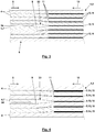
- Fig. 3 represents the thickness ratios that result when in the fiber composite component 1 in the area 2 a fiber layer 7 ending with its fiber layer end edge 9 merges into a total of seven equally thick intermediate layers 5, of which the intermediate layer 13 ends with its intermediate layer end edge 11 between the same continuous fiber layers 4 like the fiber layer 7.
- Fig. 4 shows that the intermediate layers, which end with respect to the fiber layer 7, do not all have to be of the same intermediate layer thickness. Specifically, here the two outer layers of a total of five intermediate layers 15 are thicker than the three inner intermediate layers 16.
- the average intermediate layer thickness of the intermediate layers 5 ending before the fiber layer 7 is here 1/5 of the fiber layer thickness of the fiber layer 7. In Fig. 3 this average interlayer thickness is 1/7 of the fiber layer thickness and in Fig. 2 at 1/3.
- Fig. 7 illustrates an embodiment of the fiber composite component 1, in which two fiber layers 7 end in the region 2 with their fiber layer end edges 9. A total of eight intermediate layers 5 of the same intermediate layer thickness end opposite them, two first intermediate layers 13 ending between the same continuous fiber layers 4 as the fiber layers 7 and further intermediate layers 14 between other intermediate layers 4.
- the average intermediate layer thickness here is also 1/4 of the average fiber layer thickness of the fiber layers 7 .
- the arrangement of the intermediate layers 5 is symmetrical with respect to the ending fiber layer (s) 7 which compensate for their thickness.
- the symmetry with respect to the one fiber layer 7 that ends is given itself.
- Fig. 8 is a perspective view of a surface 17 of a fiber composite component 1 according to the invention.
- a transverse hole 19 extending into the opposite surface 18 is made in the surface 17.
- the transverse hole 19 extends through cover layers 20 and a middle layer 21 and intermediate layers 22 of the fiber composite component lying between them. Only fiber layers are embedded in the resin matrix 6 in the cover layers 20 and the middle layer 21, while intermediate layers are also provided in the intermediate layers 22. This increases the stiffness of the transverse hole 19.
- a connecting hole 23 extends through the intermediate layer 22 and thus not through the intermediate layers, via which a tension element can engage a transverse bolt inserted into the transverse hole 19.
- Fig. 9 shows the position of such a transverse bolt 24 in the transverse hole 19 and a matched course of the fiber layer end edges 9 and intermediate layer end edges 11 for efficiently increasing the stiffness of the transverse hole 19 for a load in the direction of an arrow 25.
- the counterforce supporting the load 25 is indicated by arrows 35 , which are distributed over the entire width of the fiber composite component 1.
- the fiber layer end edges 9 and the intermediate layer end edges 11 do not run straight across the directions 8 and 10 over the entire width of the fiber composite component 1, but are angled toward the edge of the fiber composite component 1.
- Fig. 10 illustrates intermediate layers 5 with a surface structure.
- the intermediate layers 5 are profiled in a wave shape here. Accordingly, the adjacent fiber layers 4 are deformed in a wave shape when compressing a stack of the intermediate layers 5 and the fiber layers 4.
- This production is particularly facilitated if the area of a later transverse hole 19 is used as an additional matrix resin supply channel when infiltrating the stack with matrix resin.
- the area of a future connection hole 23 can also be used accordingly.
- the often fundamentally sheet-like intermediate layers 5 can be provided with local openings for the passage of matrix resin.
- the production method according to the invention begins with a surface structuring 26 of the intermediate layers 5.
- holes are made in the intermediate layers 5 and preferably also in the fiber layers 4, which correspond to the later transverse hole 19.
- Subsequent infiltration 29 with matrix resin takes place, inter alia, via matrix resin supply channels, which are formed by the aligned holes in the fiber layers 4 and intermediate layers 5.
- the connecting holes 23 preferably do not extend through the holes Intermediate layers 5.
Landscapes
- Chemical & Material Sciences (AREA)
- Engineering & Computer Science (AREA)
- Composite Materials (AREA)
- Mechanical Engineering (AREA)
- Laminated Bodies (AREA)
- Reinforced Plastic Materials (AREA)
- Moulding By Coating Moulds (AREA)
Claims (15)
- Pièce composite à fibres (1)- dans laquelle, dans une zone (2) s'étendant le long d'une surface principale (3),- plusieurs couches de fibres (4) parallèles à la surface principale (3) et- plusieurs couches intermédiaires (5) parallèles à la surface principale (3) sont intégrées dans une matrice en résine (6),- dans laquelle une première (7) des couches de fibres (4)- provenant d'une première direction (8)- se termine à l'intérieur de la zone (2),- avec une première arête de terminaison de couche de fibres (9) et- entre deux couches de fibres (4) adjacentes aux deux premières (7) des couches de fibres (4) et traversant dans la première direction (8) la zone (2) des couches de fibres (4) et- dans laquelle une première (13) des couches intermédiaires (5)- provenant d'une deuxième direction (10) opposée à la première direction (8),- se termine à l'intérieur de la zone (2),- avec une première arête de terminaison de couche intermédiaire (11) parallèle à la première arête de terminaison de couche de fibres (9),- avant la première arête de terminaison de couche de fibres (9) et- entre deux couches de fibres (4) adjacentes aux premières (13) des couches intermédiaires (5) et traversant dans la première direction (8) la zone (2) des couches de fibres (4), dans laquelle au moins une des deux des couches de fibres (4) adjacentes à la première couche intermédiaire (13) est une des deux couches de fibres (4) adjacentes à une des deux des premières couches de fibres (4),- dans laquelle au moins une autre (14) des couches intermédiaires (5)- provenant de la deuxième direction (10)- se termine à l'intérieur de la zone (2),- avec une autre arête de terminaison de couche intermédiaire (11) parallèle à la première arête de terminaison de couche intermédiaire (11),- entre deux couches de fibres (4) adjacentes à l'autre (14) des couches intermédiaires (5) et traversant dans la première direction (8) la zone (2) des couches de fibres, entre lesquelles ni une des couches de fibres (4) ni une autre des couches intermédiaire (5) ne se termine dans la zone (2) et- avant la première arête de terminaison de couche de fibres (9),caractérisée en ce que- une épaisseur de couche intermédiaire moyenne des couches intermédiaire (5) qui se terminent dans la zone (2) est au maximum la moitié d'une épaisseur de couche de fibres moyenne des couches de fibres (4) qui se terminent dans la zone (2) et- la pièce composite à fibres (1) présente, sur la zone (2), une épaisseur de pièce constante perpendiculairement à la surface principale (3).
- Pièce composite à fibres (1) selon la revendication 1, caractérisée en ce que, sur chaque côté des deux couches de fibres adjacentes aux premières (13) des couches intermédiaires (5) et traversant dans la première direction (8) la zone (2), au moins une des couches intermédiaires (5) se termine entre deux couches de fibres (4) traversant dans la première direction (8) la zone (2) des couches de fibres (4) dans la zone (2), entre lesquelles aucune des couches de fibres (4) ne se termine dans la zone (2).
- Pièce composite à fibres (1) selon la revendication 2, caractérisée en ce que entre les deux couches de fibres (4) de chaque paire de couches de fibres (4) adjacentes des couches de fibres (4) qui traversent la zone (2), pas plus d'une des couches intermédiaire (5) ne se termine avec l'arête de terminaison de couche intermédiaire (11).
- Pièce composite à fibres (1) selon l'une des revendications précédentes, caractérisée en ce qu'une deuxième (7) des couches de fibres (4)- provenant de la première direction (8),- se termine à l'intérieur de la zone (2),- avec une deuxième arête de terminaison de couche de fibres (9) parallèle à la première arête de terminaison de couche de fibres (9),- dans la première direction (8) à une hauteur avec l'arête de terminaison de couche de fibres (9) et- entre deux couches de fibres (4) adjacentes à la deuxième couche de fibres (7) et traversant dans la première direction (8) la zone (2), des couches de fibres (4).
- Pièce composite à fibres (1) selon l'une des revendications précédentes, caractérisée en ce que, entre les deux couches de fibres (4), qui traversent dans la première direction (8) la zone (2) et entre lesquelles la première (7) ou la deuxième (7) des couches de fibres (4) se termine avec son arête de terminaison de couche de fibres (9), une (13) des couches intermédiaires (5), provenant de la deuxième direction (10), se termine à l'intérieur de la zone (2) avec une arête de terminaison de couche intermédiaire (11) parallèle à l'arête de terminaison de couche de fibres (9) correspondante, avant l'arête de terminaison de couche de fibres (9) correspondant.
- Pièce composite à fibres (1) selon l'une des revendications précédentes, caractérisée en ce que la disposition des couches intermédiaires (5) se terminant dans la zone (2) est symétrique en miroir par rapport à un plan central des premières (7) des couches de fibres (4) ou à un plan central entre les premières (7) des couches de fibres (4) et les deuxièmes (7) des couches de fibres (4).
- Pièce composite à fibres (1) selon l'une des revendications précédentes, caractérisée en ce que la première (13) des couches intermédiaires (5) se termine, avec sa première arête de terminaison de couche intermédiaire (11) et les autres (14) des couches intermédiaires (5) se terminant avec leurs autres arêtes de terminaison de couches intermédiaires (11) dans la deuxième direction (10)- à une hauteur avant la première arête de terminaison de couches de fibres (9) ou- avant la première arête de terminaison de couche de fibres (9) dans une formation en V dans la zone (2).
- Pièce composite à fibres (1) selon l'une des revendications précédentes, caractérisée en ce que, dans la deuxième direction (10), avant l'arête de terminaison de couche intermédiaire (11) d'au moins une des couches intermédiaires (5) se terminant dans la zone (2), est intégrée un bourrage (34) dans la matrice en résine (6).
- Pièce composite à fibres (1) selon l'une des revendications précédentes, caractérisée en ce que- au moins une des couches intermédiaires (5) comprend des évidements et/ou une texturation de surface et- des trous transversaux (19) s'étendant transversalement par rapport à la surface principale (3) à travers la pièce composite à fibres (1) s'étendant à travers les couches intermédiaires (5) ou sont directement adjacents à celles-ci,- dans laquelle les évidements et/ou la texturation de surface de l'au moins une des couches intermédiaires (5) sont/est adjacente(s) localement aux trous transversaux (19).
- Pièce composite à fibres (1) selon la revendication 10, caractérisée en ce que des trous de raccordement (23) s'étendant à partir des trous transversaux (19) le long de la surface principale (3) ne s'étendent pas à travers les couches intermédiaires (5).
- Procédé pour la fabrication d'une pièce composite à fibres avec une zone (2) s'étendant le long d'une surface principale (3), dans laquelle plusieurs couches de fibres (4) parallèles à la surface principale (3) et plusieurs couches intermédiaires (5) parallèles à la surface principale (3) et non constituées de fibres sont intégrées dans une matrice en résine (6), plus particulièrement d'une pièce composite à fibres (1) selon l'une des revendications précédentes,- dans lequel, à partir des couches de fibres (4) et des couches intermédiaires (5), un empilement est formé,- dans lequel l'empilement est infiltré avec une résine de matrice et- dans lequel la résine de matrice est durcie afin d'obtenir une matrice en résine (6), caractérisé en ce que- des trous s'étendant dans l'empilement transversalement par rapport à la surface principale (3) dans les couches intermédiaires (5) sont alignés entre eux de façon à ce qu'au moins un canal d'introduction de résine de matrice conduisant de l'extérieur à travers les trous alignés dans plusieurs des couches intermédiaires (5) vers l'intérieur de l'empilement soit formé et- une résine de matrice est injectée dans l'empilement par l'intermédiaire de l'au moins un canal d'introduction de résine de matrice.
- Procédé selon la revendication 11, caractérisé en ce que- au moins une des couches intermédiaires (5) est munie, de manière adjacente au canal d'introduction de résine de matrice et/ou à sa bifurcation, d'une texturation de surface (26), dans lequel, en option, la texturation de surface (26) est réalisée par une déformation tridimensionnelle et/ou par enlèvement local de matériau de l'au moins une couche intermédiaire (5) et/ou- l'au moins un canal d'introduction de résine de matrice s'étend également à travers des trous dans les couches de fibres (4) correspondant aux trous dans les couches intermédiaires (5).
- Procédé selon la revendication 11 ou 12, caractérisé en ce que l'au moins un canal d'introduction de résine de matrice est percé après le durcissement de la résine de matrice pour la formation d'un trou traversant (19).
- Procédé selon la revendication 13, caractérisé en ce que, après la réalisation du trou traversant (19), un trou de raccordement (23) s'étendant le long de la surface principale (3) jusqu'au trou traversant (19) est réalisé dans la pièce composite à fibres (1).
- Procédé selon la revendication 14, caractérisé en ce que- de manière superposée avec le trou de raccordement (23) réalisé plus tard, un espace libre est laissé dans l'empilement grâce à des évidements dans les couches de fibres (4), afin de réaliser une bifurcation de l'au moins un canal d'introduction de résine de matrice,- dans lequel, en option, le trou de raccordement (23) n'est pas réalisé dans les couches intermédiaires (5).
Applications Claiming Priority (1)
| Application Number | Priority Date | Filing Date | Title |
|---|---|---|---|
| DE102018108851.5A DE102018108851A1 (de) | 2018-04-13 | 2018-04-13 | Faserverbundbauteil mit Zwischenlagen und Verfahren zu seiner Herstellung |
Publications (2)
| Publication Number | Publication Date |
|---|---|
| EP3552813A1 EP3552813A1 (fr) | 2019-10-16 |
| EP3552813B1 true EP3552813B1 (fr) | 2020-07-01 |
Family
ID=65801829
Family Applications (1)
| Application Number | Title | Priority Date | Filing Date |
|---|---|---|---|
| EP19160554.2A Active EP3552813B1 (fr) | 2018-04-13 | 2019-03-04 | Composant composite fibreux pourvu de couches intermédiaires et son procédé de fabrication |
Country Status (3)
| Country | Link |
|---|---|
| EP (1) | EP3552813B1 (fr) |
| DE (1) | DE102018108851A1 (fr) |
| DK (1) | DK3552813T3 (fr) |
Families Citing this family (1)
| Publication number | Priority date | Publication date | Assignee | Title |
|---|---|---|---|---|
| US20240269942A1 (en) * | 2023-02-09 | 2024-08-15 | The Boeing Company | Processing of Composites with Partial Plies |
Family Cites Families (2)
| Publication number | Priority date | Publication date | Assignee | Title |
|---|---|---|---|---|
| DE102010009769A1 (de) * | 2010-03-01 | 2011-09-01 | Deutsches Zentrum für Luft- und Raumfahrt e.V. | Verbundwerkstoff aus mehreren Faserverbundschichten und einem Verstärkungsbereich |
| GB201103125D0 (en) * | 2011-02-23 | 2011-04-06 | Airbus Uk Ltd | Composite structure |
-
2018
- 2018-04-13 DE DE102018108851.5A patent/DE102018108851A1/de not_active Withdrawn
-
2019
- 2019-03-04 EP EP19160554.2A patent/EP3552813B1/fr active Active
- 2019-03-04 DK DK19160554.2T patent/DK3552813T3/da active
Also Published As
| Publication number | Publication date |
|---|---|
| DK3552813T3 (da) | 2020-08-31 |
| EP3552813A1 (fr) | 2019-10-16 |
| DE102018108851A1 (de) | 2019-10-17 |
Similar Documents
| Publication | Publication Date | Title |
|---|---|---|
| EP3018342B1 (fr) | Procede de fabrication d'une pale de rotor d'eolienne | |
| EP2815861B1 (fr) | Procédé et outil de formage pour la fabrication d'un segment de membrure pour une pale de rotor d'installation éolienne | |
| EP4061605B1 (fr) | Conception de bord d'une structure de raidissage plate pour un composant | |
| DE3412846A1 (de) | Flaechenfoermiger sandwichformkoerper | |
| DE102015007289A1 (de) | Rotorblatt, Rotorblattgurt und Verfahren zum Herstellen eines Rotorblattgurts | |
| EP0082321B1 (fr) | Ressort à flexion en matière plastique renforcée de fibres et presse pour sa fabrication | |
| WO2004104315A1 (fr) | Composant comportant une structure auxetique | |
| DE102008024585B4 (de) | Federelement für eine Feder-Dämpfer-Anordnung | |
| EP3354450A1 (fr) | Profilé pultrudé pour un composant structurel d'éolienne | |
| WO2011006562A2 (fr) | Pale rotorique d'une éolienne, procédé de production d'une pale rotorique et paire de courroies pour une pale rotorique | |
| EP3604797B1 (fr) | Bande de produit de pultrusion rétrécie et son procédé de fabrication | |
| EP2897788B1 (fr) | Élément composite renforcé par des fibres optimisé fonctionnellement, et procédé de fabrication dudit élément composite | |
| EP4117884B1 (fr) | Pièce fonctionnalisée et étanche | |
| EP3551438B1 (fr) | Membrure de bord de fuite d'une pale de rotor d'une installation éolienne, pale de rotor et procédé de fabrication d'une membrure de bord de fuite | |
| EP3552813B1 (fr) | Composant composite fibreux pourvu de couches intermédiaires et son procédé de fabrication | |
| DE102017126276A1 (de) | Verfahren zur Herstellung einer Steg-Gurt-Baugruppe für ein Windenergieanlagenrotorblatt und Steg-Gurt-Baugruppe | |
| DE102010030550B4 (de) | Verbundbauteil mit einem Gewebe mit integrierten Profilen | |
| EP4017697B1 (fr) | Procédé de production d'un composant structurel | |
| EP2607058A1 (fr) | Élément structurel à symétrie de rotation dans la construction de grilles et son procédé de fabrication | |
| DE102004045845B3 (de) | Faserverbundstruktur mit einer Bolzenverbindung und Herstellungsverfahren dafür | |
| DE102008048857A1 (de) | Rotorblatt mit Stegverzweigung | |
| DE102020005020A1 (de) | Tragrahmen für eine Batterie | |
| WO2021239769A1 (fr) | Panneau fonctionnel asymétrique | |
| EP3077202A1 (fr) | Pièce préformée plane porteuse en matériau composite renforcé par des fibres et stratifié, destinée notamment à une carrosserie de véhicule | |
| DE102023200894A1 (de) | Mehrpunktlenker für ein Fahrwerk eines Nutzkraftfahrzeugs |
Legal Events
| Date | Code | Title | Description |
|---|---|---|---|
| PUAI | Public reference made under article 153(3) epc to a published international application that has entered the european phase |
Free format text: ORIGINAL CODE: 0009012 |
|
| STAA | Information on the status of an ep patent application or granted ep patent |
Free format text: STATUS: THE APPLICATION HAS BEEN PUBLISHED |
|
| AK | Designated contracting states |
Kind code of ref document: A1 Designated state(s): AL AT BE BG CH CY CZ DE DK EE ES FI FR GB GR HR HU IE IS IT LI LT LU LV MC MK MT NL NO PL PT RO RS SE SI SK SM TR |
|
| AX | Request for extension of the european patent |
Extension state: BA ME |
|
| STAA | Information on the status of an ep patent application or granted ep patent |
Free format text: STATUS: REQUEST FOR EXAMINATION WAS MADE |
|
| 17P | Request for examination filed |
Effective date: 20191128 |
|
| RBV | Designated contracting states (corrected) |
Designated state(s): AL AT BE BG CH CY CZ DE DK EE ES FI FR GB GR HR HU IE IS IT LI LT LU LV MC MK MT NL NO PL PT RO RS SE SI SK SM TR |
|
| GRAP | Despatch of communication of intention to grant a patent |
Free format text: ORIGINAL CODE: EPIDOSNIGR1 |
|
| STAA | Information on the status of an ep patent application or granted ep patent |
Free format text: STATUS: GRANT OF PATENT IS INTENDED |
|
| INTG | Intention to grant announced |
Effective date: 20200207 |
|
| GRAS | Grant fee paid |
Free format text: ORIGINAL CODE: EPIDOSNIGR3 |
|
| GRAA | (expected) grant |
Free format text: ORIGINAL CODE: 0009210 |
|
| STAA | Information on the status of an ep patent application or granted ep patent |
Free format text: STATUS: THE PATENT HAS BEEN GRANTED |
|
| AK | Designated contracting states |
Kind code of ref document: B1 Designated state(s): AL AT BE BG CH CY CZ DE DK EE ES FI FR GB GR HR HU IE IS IT LI LT LU LV MC MK MT NL NO PL PT RO RS SE SI SK SM TR |
|
| REG | Reference to a national code |
Ref country code: CH Ref legal event code: EP Ref country code: AT Ref legal event code: REF Ref document number: 1285780 Country of ref document: AT Kind code of ref document: T Effective date: 20200715 |
|
| REG | Reference to a national code |
Ref country code: IE Ref legal event code: FG4D Free format text: LANGUAGE OF EP DOCUMENT: GERMAN |
|
| REG | Reference to a national code |
Ref country code: DE Ref legal event code: R096 Ref document number: 502019000074 Country of ref document: DE |
|
| REG | Reference to a national code |
Ref country code: DK Ref legal event code: T3 Effective date: 20200826 |
|
| REG | Reference to a national code |
Ref country code: LT Ref legal event code: MG4D |
|
| PG25 | Lapsed in a contracting state [announced via postgrant information from national office to epo] |
Ref country code: BG Free format text: LAPSE BECAUSE OF FAILURE TO SUBMIT A TRANSLATION OF THE DESCRIPTION OR TO PAY THE FEE WITHIN THE PRESCRIBED TIME-LIMIT Effective date: 20201001 |
|
| REG | Reference to a national code |
Ref country code: NL Ref legal event code: MP Effective date: 20200701 |
|
| PG25 | Lapsed in a contracting state [announced via postgrant information from national office to epo] |
Ref country code: FI Free format text: LAPSE BECAUSE OF FAILURE TO SUBMIT A TRANSLATION OF THE DESCRIPTION OR TO PAY THE FEE WITHIN THE PRESCRIBED TIME-LIMIT Effective date: 20200701 Ref country code: CZ Free format text: LAPSE BECAUSE OF FAILURE TO SUBMIT A TRANSLATION OF THE DESCRIPTION OR TO PAY THE FEE WITHIN THE PRESCRIBED TIME-LIMIT Effective date: 20200701 Ref country code: PT Free format text: LAPSE BECAUSE OF FAILURE TO SUBMIT A TRANSLATION OF THE DESCRIPTION OR TO PAY THE FEE WITHIN THE PRESCRIBED TIME-LIMIT Effective date: 20201102 Ref country code: LT Free format text: LAPSE BECAUSE OF FAILURE TO SUBMIT A TRANSLATION OF THE DESCRIPTION OR TO PAY THE FEE WITHIN THE PRESCRIBED TIME-LIMIT Effective date: 20200701 Ref country code: ES Free format text: LAPSE BECAUSE OF FAILURE TO SUBMIT A TRANSLATION OF THE DESCRIPTION OR TO PAY THE FEE WITHIN THE PRESCRIBED TIME-LIMIT Effective date: 20200701 Ref country code: GR Free format text: LAPSE BECAUSE OF FAILURE TO SUBMIT A TRANSLATION OF THE DESCRIPTION OR TO PAY THE FEE WITHIN THE PRESCRIBED TIME-LIMIT Effective date: 20201002 Ref country code: NO Free format text: LAPSE BECAUSE OF FAILURE TO SUBMIT A TRANSLATION OF THE DESCRIPTION OR TO PAY THE FEE WITHIN THE PRESCRIBED TIME-LIMIT Effective date: 20201001 Ref country code: HR Free format text: LAPSE BECAUSE OF FAILURE TO SUBMIT A TRANSLATION OF THE DESCRIPTION OR TO PAY THE FEE WITHIN THE PRESCRIBED TIME-LIMIT Effective date: 20200701 Ref country code: SE Free format text: LAPSE BECAUSE OF FAILURE TO SUBMIT A TRANSLATION OF THE DESCRIPTION OR TO PAY THE FEE WITHIN THE PRESCRIBED TIME-LIMIT Effective date: 20200701 |
|
| PG25 | Lapsed in a contracting state [announced via postgrant information from national office to epo] |
Ref country code: PL Free format text: LAPSE BECAUSE OF FAILURE TO SUBMIT A TRANSLATION OF THE DESCRIPTION OR TO PAY THE FEE WITHIN THE PRESCRIBED TIME-LIMIT Effective date: 20200701 Ref country code: RS Free format text: LAPSE BECAUSE OF FAILURE TO SUBMIT A TRANSLATION OF THE DESCRIPTION OR TO PAY THE FEE WITHIN THE PRESCRIBED TIME-LIMIT Effective date: 20200701 Ref country code: LV Free format text: LAPSE BECAUSE OF FAILURE TO SUBMIT A TRANSLATION OF THE DESCRIPTION OR TO PAY THE FEE WITHIN THE PRESCRIBED TIME-LIMIT Effective date: 20200701 Ref country code: IS Free format text: LAPSE BECAUSE OF FAILURE TO SUBMIT A TRANSLATION OF THE DESCRIPTION OR TO PAY THE FEE WITHIN THE PRESCRIBED TIME-LIMIT Effective date: 20201101 |
|
| PG25 | Lapsed in a contracting state [announced via postgrant information from national office to epo] |
Ref country code: NL Free format text: LAPSE BECAUSE OF FAILURE TO SUBMIT A TRANSLATION OF THE DESCRIPTION OR TO PAY THE FEE WITHIN THE PRESCRIBED TIME-LIMIT Effective date: 20200701 |
|
| REG | Reference to a national code |
Ref country code: DE Ref legal event code: R097 Ref document number: 502019000074 Country of ref document: DE |
|
| PG25 | Lapsed in a contracting state [announced via postgrant information from national office to epo] |
Ref country code: IT Free format text: LAPSE BECAUSE OF FAILURE TO SUBMIT A TRANSLATION OF THE DESCRIPTION OR TO PAY THE FEE WITHIN THE PRESCRIBED TIME-LIMIT Effective date: 20200701 Ref country code: SM Free format text: LAPSE BECAUSE OF FAILURE TO SUBMIT A TRANSLATION OF THE DESCRIPTION OR TO PAY THE FEE WITHIN THE PRESCRIBED TIME-LIMIT Effective date: 20200701 Ref country code: EE Free format text: LAPSE BECAUSE OF FAILURE TO SUBMIT A TRANSLATION OF THE DESCRIPTION OR TO PAY THE FEE WITHIN THE PRESCRIBED TIME-LIMIT Effective date: 20200701 Ref country code: RO Free format text: LAPSE BECAUSE OF FAILURE TO SUBMIT A TRANSLATION OF THE DESCRIPTION OR TO PAY THE FEE WITHIN THE PRESCRIBED TIME-LIMIT Effective date: 20200701 |
|
| PLBE | No opposition filed within time limit |
Free format text: ORIGINAL CODE: 0009261 |
|
| STAA | Information on the status of an ep patent application or granted ep patent |
Free format text: STATUS: NO OPPOSITION FILED WITHIN TIME LIMIT |
|
| PG25 | Lapsed in a contracting state [announced via postgrant information from national office to epo] |
Ref country code: AL Free format text: LAPSE BECAUSE OF FAILURE TO SUBMIT A TRANSLATION OF THE DESCRIPTION OR TO PAY THE FEE WITHIN THE PRESCRIBED TIME-LIMIT Effective date: 20200701 |
|
| 26N | No opposition filed |
Effective date: 20210406 |
|
| PG25 | Lapsed in a contracting state [announced via postgrant information from national office to epo] |
Ref country code: SK Free format text: LAPSE BECAUSE OF FAILURE TO SUBMIT A TRANSLATION OF THE DESCRIPTION OR TO PAY THE FEE WITHIN THE PRESCRIBED TIME-LIMIT Effective date: 20200701 |
|
| PG25 | Lapsed in a contracting state [announced via postgrant information from national office to epo] |
Ref country code: SI Free format text: LAPSE BECAUSE OF FAILURE TO SUBMIT A TRANSLATION OF THE DESCRIPTION OR TO PAY THE FEE WITHIN THE PRESCRIBED TIME-LIMIT Effective date: 20200701 |
|
| PG25 | Lapsed in a contracting state [announced via postgrant information from national office to epo] |
Ref country code: MC Free format text: LAPSE BECAUSE OF FAILURE TO SUBMIT A TRANSLATION OF THE DESCRIPTION OR TO PAY THE FEE WITHIN THE PRESCRIBED TIME-LIMIT Effective date: 20200701 |
|
| REG | Reference to a national code |
Ref country code: BE Ref legal event code: MM Effective date: 20210331 |
|
| PG25 | Lapsed in a contracting state [announced via postgrant information from national office to epo] |
Ref country code: LU Free format text: LAPSE BECAUSE OF NON-PAYMENT OF DUE FEES Effective date: 20210304 Ref country code: IE Free format text: LAPSE BECAUSE OF NON-PAYMENT OF DUE FEES Effective date: 20210304 |
|
| PG25 | Lapsed in a contracting state [announced via postgrant information from national office to epo] |
Ref country code: BE Free format text: LAPSE BECAUSE OF NON-PAYMENT OF DUE FEES Effective date: 20210331 |
|
| REG | Reference to a national code |
Ref country code: CH Ref legal event code: PL |
|
| PG25 | Lapsed in a contracting state [announced via postgrant information from national office to epo] |
Ref country code: LI Free format text: LAPSE BECAUSE OF NON-PAYMENT OF DUE FEES Effective date: 20220331 Ref country code: CH Free format text: LAPSE BECAUSE OF NON-PAYMENT OF DUE FEES Effective date: 20220331 |
|
| PG25 | Lapsed in a contracting state [announced via postgrant information from national office to epo] |
Ref country code: CY Free format text: LAPSE BECAUSE OF FAILURE TO SUBMIT A TRANSLATION OF THE DESCRIPTION OR TO PAY THE FEE WITHIN THE PRESCRIBED TIME-LIMIT Effective date: 20200701 |
|
| PG25 | Lapsed in a contracting state [announced via postgrant information from national office to epo] |
Ref country code: HU Free format text: LAPSE BECAUSE OF FAILURE TO SUBMIT A TRANSLATION OF THE DESCRIPTION OR TO PAY THE FEE WITHIN THE PRESCRIBED TIME-LIMIT; INVALID AB INITIO Effective date: 20190304 |
|
| PG25 | Lapsed in a contracting state [announced via postgrant information from national office to epo] |
Ref country code: MK Free format text: LAPSE BECAUSE OF FAILURE TO SUBMIT A TRANSLATION OF THE DESCRIPTION OR TO PAY THE FEE WITHIN THE PRESCRIBED TIME-LIMIT Effective date: 20200701 |
|
| PG25 | Lapsed in a contracting state [announced via postgrant information from national office to epo] |
Ref country code: MT Free format text: LAPSE BECAUSE OF FAILURE TO SUBMIT A TRANSLATION OF THE DESCRIPTION OR TO PAY THE FEE WITHIN THE PRESCRIBED TIME-LIMIT Effective date: 20200701 |
|
| PGFP | Annual fee paid to national office [announced via postgrant information from national office to epo] |
Ref country code: DK Payment date: 20250225 Year of fee payment: 7 |
|
| PGFP | Annual fee paid to national office [announced via postgrant information from national office to epo] |
Ref country code: FR Payment date: 20250211 Year of fee payment: 7 |
|
| PGFP | Annual fee paid to national office [announced via postgrant information from national office to epo] |
Ref country code: GB Payment date: 20250213 Year of fee payment: 7 |
|
| REG | Reference to a national code |
Ref country code: AT Ref legal event code: MM01 Ref document number: 1285780 Country of ref document: AT Kind code of ref document: T Effective date: 20240304 |
|
| PG25 | Lapsed in a contracting state [announced via postgrant information from national office to epo] |
Ref country code: AT Free format text: LAPSE BECAUSE OF NON-PAYMENT OF DUE FEES Effective date: 20240304 |
|
| PG25 | Lapsed in a contracting state [announced via postgrant information from national office to epo] |
Ref country code: TR Free format text: LAPSE BECAUSE OF FAILURE TO SUBMIT A TRANSLATION OF THE DESCRIPTION OR TO PAY THE FEE WITHIN THE PRESCRIBED TIME-LIMIT Effective date: 20200701 |
|
| PGFP | Annual fee paid to national office [announced via postgrant information from national office to epo] |
Ref country code: DE Payment date: 20260213 Year of fee payment: 8 |
|
| PGFP | Annual fee paid to national office [announced via postgrant information from national office to epo] |
Ref country code: AT Payment date: 20260410 Year of fee payment: 5 |