EP3552858A1 - Ladestecker für eine elektrische fahrzeugladestation, wobei die ladestation den ladestecker und einen ladeempfänger für ein elektrofahrzeug umfasst - Google Patents
Ladestecker für eine elektrische fahrzeugladestation, wobei die ladestation den ladestecker und einen ladeempfänger für ein elektrofahrzeug umfasst Download PDFInfo
- Publication number
- EP3552858A1 EP3552858A1 EP18305426.1A EP18305426A EP3552858A1 EP 3552858 A1 EP3552858 A1 EP 3552858A1 EP 18305426 A EP18305426 A EP 18305426A EP 3552858 A1 EP3552858 A1 EP 3552858A1
- Authority
- EP
- European Patent Office
- Prior art keywords
- electric
- fluid
- connector
- charger plug
- protrusion
- Prior art date
- Legal status (The legal status is an assumption and is not a legal conclusion. Google has not performed a legal analysis and makes no representation as to the accuracy of the status listed.)
- Granted
Links
Images




Classifications
-
- B—PERFORMING OPERATIONS; TRANSPORTING
- B60—VEHICLES IN GENERAL
- B60L—PROPULSION OF ELECTRICALLY-PROPELLED VEHICLES; SUPPLYING ELECTRIC POWER FOR AUXILIARY EQUIPMENT OF ELECTRICALLY-PROPELLED VEHICLES; ELECTRODYNAMIC BRAKE SYSTEMS FOR VEHICLES IN GENERAL; MAGNETIC SUSPENSION OR LEVITATION FOR VEHICLES; MONITORING OPERATING VARIABLES OF ELECTRICALLY-PROPELLED VEHICLES; ELECTRIC SAFETY DEVICES FOR ELECTRICALLY-PROPELLED VEHICLES
- B60L1/00—Supplying electric power to auxiliary equipment of vehicles
-
- B—PERFORMING OPERATIONS; TRANSPORTING
- B60—VEHICLES IN GENERAL
- B60L—PROPULSION OF ELECTRICALLY-PROPELLED VEHICLES; SUPPLYING ELECTRIC POWER FOR AUXILIARY EQUIPMENT OF ELECTRICALLY-PROPELLED VEHICLES; ELECTRODYNAMIC BRAKE SYSTEMS FOR VEHICLES IN GENERAL; MAGNETIC SUSPENSION OR LEVITATION FOR VEHICLES; MONITORING OPERATING VARIABLES OF ELECTRICALLY-PROPELLED VEHICLES; ELECTRIC SAFETY DEVICES FOR ELECTRICALLY-PROPELLED VEHICLES
- B60L53/00—Methods of charging batteries, specially adapted for electric vehicles; Charging stations or on-board charging equipment therefor; Exchange of energy storage elements in electric vehicles
- B60L53/10—Methods of charging batteries, specially adapted for electric vehicles; Charging stations or on-board charging equipment therefor; Exchange of energy storage elements in electric vehicles characterised by the energy transfer between the charging station and the vehicle
- B60L53/14—Conductive energy transfer
- B60L53/16—Connectors, e.g. plugs or sockets, specially adapted for charging electric vehicles
-
- B—PERFORMING OPERATIONS; TRANSPORTING
- B60—VEHICLES IN GENERAL
- B60L—PROPULSION OF ELECTRICALLY-PROPELLED VEHICLES; SUPPLYING ELECTRIC POWER FOR AUXILIARY EQUIPMENT OF ELECTRICALLY-PROPELLED VEHICLES; ELECTRODYNAMIC BRAKE SYSTEMS FOR VEHICLES IN GENERAL; MAGNETIC SUSPENSION OR LEVITATION FOR VEHICLES; MONITORING OPERATING VARIABLES OF ELECTRICALLY-PROPELLED VEHICLES; ELECTRIC SAFETY DEVICES FOR ELECTRICALLY-PROPELLED VEHICLES
- B60L53/00—Methods of charging batteries, specially adapted for electric vehicles; Charging stations or on-board charging equipment therefor; Exchange of energy storage elements in electric vehicles
- B60L53/20—Methods of charging batteries, specially adapted for electric vehicles; Charging stations or on-board charging equipment therefor; Exchange of energy storage elements in electric vehicles characterised by converters located in the vehicle
- B60L53/22—Constructional details or arrangements of charging converters specially adapted for charging electric vehicles
-
- B—PERFORMING OPERATIONS; TRANSPORTING
- B60—VEHICLES IN GENERAL
- B60L—PROPULSION OF ELECTRICALLY-PROPELLED VEHICLES; SUPPLYING ELECTRIC POWER FOR AUXILIARY EQUIPMENT OF ELECTRICALLY-PROPELLED VEHICLES; ELECTRODYNAMIC BRAKE SYSTEMS FOR VEHICLES IN GENERAL; MAGNETIC SUSPENSION OR LEVITATION FOR VEHICLES; MONITORING OPERATING VARIABLES OF ELECTRICALLY-PROPELLED VEHICLES; ELECTRIC SAFETY DEVICES FOR ELECTRICALLY-PROPELLED VEHICLES
- B60L53/00—Methods of charging batteries, specially adapted for electric vehicles; Charging stations or on-board charging equipment therefor; Exchange of energy storage elements in electric vehicles
- B60L53/30—Constructional details of charging stations
-
- H—ELECTRICITY
- H01—ELECTRIC ELEMENTS
- H01R—ELECTRICALLY-CONDUCTIVE CONNECTIONS; STRUCTURAL ASSOCIATIONS OF A PLURALITY OF MUTUALLY-INSULATED ELECTRICAL CONNECTING ELEMENTS; COUPLING DEVICES; CURRENT COLLECTORS
- H01R13/00—Details of coupling devices of the kinds covered by groups H01R12/70 or H01R24/00 - H01R33/00
- H01R13/005—Electrical coupling combined with fluidic coupling
-
- Y—GENERAL TAGGING OF NEW TECHNOLOGICAL DEVELOPMENTS; GENERAL TAGGING OF CROSS-SECTIONAL TECHNOLOGIES SPANNING OVER SEVERAL SECTIONS OF THE IPC; TECHNICAL SUBJECTS COVERED BY FORMER USPC CROSS-REFERENCE ART COLLECTIONS [XRACs] AND DIGESTS
- Y02—TECHNOLOGIES OR APPLICATIONS FOR MITIGATION OR ADAPTATION AGAINST CLIMATE CHANGE
- Y02T—CLIMATE CHANGE MITIGATION TECHNOLOGIES RELATED TO TRANSPORTATION
- Y02T10/00—Road transport of goods or passengers
- Y02T10/60—Other road transportation technologies with climate change mitigation effect
- Y02T10/70—Energy storage systems for electromobility, e.g. batteries
-
- Y—GENERAL TAGGING OF NEW TECHNOLOGICAL DEVELOPMENTS; GENERAL TAGGING OF CROSS-SECTIONAL TECHNOLOGIES SPANNING OVER SEVERAL SECTIONS OF THE IPC; TECHNICAL SUBJECTS COVERED BY FORMER USPC CROSS-REFERENCE ART COLLECTIONS [XRACs] AND DIGESTS
- Y02—TECHNOLOGIES OR APPLICATIONS FOR MITIGATION OR ADAPTATION AGAINST CLIMATE CHANGE
- Y02T—CLIMATE CHANGE MITIGATION TECHNOLOGIES RELATED TO TRANSPORTATION
- Y02T10/00—Road transport of goods or passengers
- Y02T10/60—Other road transportation technologies with climate change mitigation effect
- Y02T10/7072—Electromobility specific charging systems or methods for batteries, ultracapacitors, supercapacitors or double-layer capacitors
-
- Y—GENERAL TAGGING OF NEW TECHNOLOGICAL DEVELOPMENTS; GENERAL TAGGING OF CROSS-SECTIONAL TECHNOLOGIES SPANNING OVER SEVERAL SECTIONS OF THE IPC; TECHNICAL SUBJECTS COVERED BY FORMER USPC CROSS-REFERENCE ART COLLECTIONS [XRACs] AND DIGESTS
- Y02—TECHNOLOGIES OR APPLICATIONS FOR MITIGATION OR ADAPTATION AGAINST CLIMATE CHANGE
- Y02T—CLIMATE CHANGE MITIGATION TECHNOLOGIES RELATED TO TRANSPORTATION
- Y02T90/00—Enabling technologies or technologies with a potential or indirect contribution to GHG emissions mitigation
- Y02T90/10—Technologies relating to charging of electric vehicles
- Y02T90/12—Electric charging stations
-
- Y—GENERAL TAGGING OF NEW TECHNOLOGICAL DEVELOPMENTS; GENERAL TAGGING OF CROSS-SECTIONAL TECHNOLOGIES SPANNING OVER SEVERAL SECTIONS OF THE IPC; TECHNICAL SUBJECTS COVERED BY FORMER USPC CROSS-REFERENCE ART COLLECTIONS [XRACs] AND DIGESTS
- Y02—TECHNOLOGIES OR APPLICATIONS FOR MITIGATION OR ADAPTATION AGAINST CLIMATE CHANGE
- Y02T—CLIMATE CHANGE MITIGATION TECHNOLOGIES RELATED TO TRANSPORTATION
- Y02T90/00—Enabling technologies or technologies with a potential or indirect contribution to GHG emissions mitigation
- Y02T90/10—Technologies relating to charging of electric vehicles
- Y02T90/14—Plug-in electric vehicles
Definitions
- the invention relates to the field of electric vehicles. More specifically, the invention relates to a charger plug, to a charging station comprising said charger plug and to a charging receiver for an electric vehicle.
- the document US 2017/0096073 A1 discloses an underground system of a charging station that provides electric charging and cooling of an electric vehicle.
- This underground system is configured to provide both electric charging and thermal conditioning of the electric vehicle and therefore has an electric line and a fluid line.
- the electric line is coupled to an electric connector and the fluid line is coupled to a fluid connector.
- the electric vehicle comprises a fluid connector that can be connected to the fluid connector of the underground system and an electric connector that can be connected to the electric connector of the underground system.
- the aim of the invention is to propose an improved and reliable fluid and electric connection solution.
- the present invention relates to a charger plug for supplying electric energy to an electric vehicle and for supplying cooling of the electric vehicle, the charger plug comprising at least a first electric connector comprising a first electric contact and at least a second electric contact, the first electric connector being arranged to be coupled with a corresponding second electric connector of a charging receiver, so that the first and second electric contacts being electrically connected with corresponding first and second electric contacts of the second electric connector, and comprising a first fluid connector comprising a first fluid inlet duct and a second fluid outlet duct, the first fluid connector being arranged to be coupled with a corresponding second fluid connector of the charging receiver, so that the first fluid inlet duct being connected with a corresponding third fluid outlet duct of the second fluid connector and that the second fluid outlet duct being connected with a corresponding fourth fluid inlet duct of the second fluid connector, charger plug characterized in that the first electric contact is located on a first protrusion and the second electric contact is located on a second protrusion, the first fluid inlet duct
- the invention also relates to a charging station comprising a charger plug according to the invention.
- the invention also relates to a charging receiver for an electric vehicle arranged to be coupled with the charger plug according to the invention, the charging receiver comprising a second electric connector arranged to be coupled with the first electric connector of the charger plug, the second electric connector comprising at least a first electric contact and a second electric contact arranged to be electrically coupled with corresponding first and second electric contacts of the first electric connector of the charger plug, and comprising a second fluid connector comprising a third fluid outlet duct and a fourth fluid inlet duct, the second fluid connector being arranged to be coupled with the corresponding first fluid connector of the charger plug, so that the third fluid outlet duct being connected with a corresponding first fluid inlet duct of the first fluid connector and the fourth fluid inlet duct being connected with a corresponding second fluid outlet duct of the first fluid connector, charging receiver characterized in that the second electric connector comprises a first recess where the first electric contact is located and where the third fluid outlet duct leads and a second recess where the second electric contact is located and where the fourth fluid inlet duct
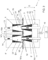
- the charger plug 2 is characterized in that the first electric contact 5 is located on a first protrusion and the second electric contact 5' is located on a second protrusion, the first fluid inlet duct 10 passing through the first protrusion and the second fluid outlet duct 11 passing through the second protrusion.
- the first fluid inlet duct 10 and the second fluid outlet duct extend in the insertion direction D ( figures 1 , 3 and 5 ).
- the first protrusion has a truncated cone shape and the second protrusion has a truncated cone shape.
- first and second protrusions is provided to ease the insertion of the first electric connector 4 and of the first fluid connector 9 in the corresponding first and second recesses 20, 20' of the charging receiver 8, described hereinafter.
- the first fluid inlet duct 10 leads to the bases B1, B2 of the truncated cone.
- the second fluid outlet duct 11 leads to the bases B1, B2 of the truncated cone.
- the first electric contact 5 covers the external wall of the first protrusion.
- the second electric contact 5' covers the external wall of the second protrusion.
- the first fluid inlet duct 10 and the second fluid outlet duct 11 have a hollow cylindrical shape.
- the truncated cone shaped first protrusion and the hollow cylindrical shaped first fluid inlet duct 10 are coaxial and the truncated cone shaped second protrusion and the hollow cylindrical shaped second fluid outlet duct 11 are coaxial ( figures 1 to 5 ).
- This arrangement enables a uniform cooling of the first electric contact 5 and of the second electric contact 5'.
- the charger plug 2 comprises a first electric connector 4 comprising a first electric contact, a second electric contact and a third electric contact.
- One of these contacts is suitable to be electrically connected to a first AC line of a power supply, one of these contacts is suitable to be electrically connected to a neutral line of the power supply, and one of these contacts is suitable to be electrically connected to a ground line.
- the charger plug 2 comprises a first electric connector 4 comprising a first electric contact, a second electric contact, a third electric contact, a fourth electric contact and a fifth electric contact.
- a first electric connector 4 comprising a first electric contact, a second electric contact, a third electric contact, a fourth electric contact and a fifth electric contact.
- One of these contacts is suitable to be electrically connected to a first AC line of a power supply, one of these contacts is suitable to be electrically connected to a second AC line of the power supply, one of these contacts is suitable to be electrically connected to a third AC line of the power supply, one of these contacts is suitable to be electrically connected to a neutral line of the power supply, one of these contacts is suitable to be electrically connected to a ground line.
- the charger plug 2 comprises a first electric connector 4 comprising a first electric contact, a second electric contact and a third electric contact.
- One of these contacts is suitable to be electrically connected to a first negative DC line of a power supply, one of these contacts is suitable to be electrically connected to a second positive DC line of the power supply and one of these contacts is suitable to be electrically connected to a ground line.
- the first electric connector 4 comprises a first communication contact and a second communication contact.
- the first electric connector 4 is a standard connector according to the standard IEC 62196-1/-2/-3.
- the invention also relates to a charging station 1 comprising a charger plug 2 according the invention.
- the charging station 1 comprises a support 15 which bears the first electric connector 4 and the first fluid connector 9 of the charger plug 2, the first electric connector 4 and the first fluid connector 9 being connected to the support 15 by return means 16.
- these return means 16 enable to exert a force on the first and second recesses 20, 20' to avoid the decoupling of the charger plug 2 and the charging receiver 8.
- the return means 16 consist in resilient means, for instance in a spring.
- the charging station 1 comprises a protection housing 17 arranged to protect the charger plug 2 ( figures 2 , 3 and 4 ).
- the protection housing 17 is provided to protect the charger plug 2 from the outdoor conditions, when the charging station 1 is not in used.
- the protection housing 17 comprises a first protection lid 18 and a second protection lid 18' arranged to be movable between a closed or semi-closed position and an open position, the first protection lid 18 and the second protection lid 18' being arranged to move from the closed position to the open position, when the first protrusion and the second protrusion lean against the first protection lid 18 and the second protection lid 18' respectively ( figures 2 , 3 and 4 ).
- This arrangement enables the automatic opening of the first and second protection lids 18, 18', when the charger plug 2 is moved outside the protection housing 17.
- These first and second cleaning means 19, 19' are provided to clean the first and second electric contacts 5, 5', when the charger plug 2 is moved outside the protection housing 17.
- the first protection lid 18 and the second protection lid 18' each consists in a pair of shutter 18a, 18b; 18'a, 18'b.
- the first cleaning means 19 and second cleaning means 19' are preferably located on the edge of the shutter 18a, 18b; 18'a, 18'b.
- the first and second cleaning means 19, 19' consist in rough or sharp-edged material, such as hard plastics, metal grater, or brush like material such as metal brush, hard fiber brush.
- the charging station 1 comprises at least a power supply system (not shown) to provide electric energy.
- the charging station 1 comprises at least a supply cable (not shown) electrically connected to the charger plug 2, more particularly to the first electric connector 4 and to the power supply system.
- the charging station 1 comprises a cooling system (not shown) to maintain the battery within an acceptable temperature range during a charging session.
- the charging station 1 comprises fluid lines (not shown), which are connected on the one hand to the charger plug 2, more particularly to the first fluid inlet duct 10 and the second fluid outlet duct 11, and on the other hand to the cooling system.
- the figures 1 , 3 , 4 and 5 show a charging receiver 8 for an electric vehicle arranged to be coupled with the charger plug 2 according to the invention, the charging receiver 8 comprising a second electric connector 7 arranged to be coupled with the first electric connector 4 of the charger plug 2, the second electric connector 7 comprising at least a first electric contact 6 and a second electric contact 6' arranged to be electrically coupled with corresponding first and second electric contacts 5, 5' of the first electric connector 4 of the charger plug 2, and comprising a second fluid connector 12 comprising a third fluid outlet duct 13 and a fourth fluid inlet duct 14, the second fluid connector 12 being arranged to be coupled with the corresponding first fluid connector 9 of the charger plug 2, so that the third fluid outlet duct 13 being connected with a corresponding first fluid inlet duct 10 of the first fluid connector 9 and the fourth fluid inlet duct 14 being connected with a corresponding second fluid outlet duct 11 of the first fluid connector 9,
- the charging receiver 8 is characterized in that the second electric connector 7 comprises a first recess 20 where the first electric contact 6 is located and where the third fluid outlet duct 13 leads and a second recess 20' where the second electric contact 6' is located and where the fourth fluid inlet duct 14 leads, these first and second recesses 20, 20' each comprising a reception opening 21, 21' to enable the insertion respectively of the first protrusion and the second protrusion of the charger plug 2.
- the charging receiver 8 enables an improved and reliable connection. Moreover, as one electric contact 6, 6' and one fluid outlet/inlet duct 13, 14 are located on the same recess 20, 20', the size of the charging receiver 8 is decreased and thus the charging receiver 8 is compact.
- the first recess 20 has a truncated cone shape and the second recess 20' has a truncated cone shape.
- This particular shape of the first and second recesses 20, 20' is provided to ease the insertion of the first and second protrusions of the charger plug 2.
- the first electric contact 6 covers the external wall of the first recess 20.
- the second electric contact 6' covers the external wall of the second recess 20'.
- the third fluid outlet duct 13 and the fourth fluid inlet duct 14 have a hollow cylindrical shape.
- the truncated cone shaped first recess 20 and the hollow cylindrical shaped third fluid outlet duct 13 are coaxial and the truncated cone shaped second recess 20' and the hollow cylindrical shaped fourth fluid inlet duct 14 are coaxial ( figures 1 , 3 to 5 ).
- the first recess 20 comprises a first lateral part 22 comprising the first electric contact 6 which is connected to the first lateral part 22 by return means 24 and the second recess 20' comprises a second lateral part 23 comprising the second electric contact 6' which is connected to the second lateral part 23 by return means 25.
- these return means 24, 25 enables to exert a force on the first and second protrusions to avoid the decoupling of the charger plug 2 and the charging receiver 8.
- the return means 24, 25 consist in resilient means, for instance in a spring.
- the electric vehicle comprises a battery (not shown).
- the electric vehicle comprises a rectifier, which connects the first AC line electrically and indirectly to the battery, and converts an alternating current (AC) current in direct current (DC), which one is required to charge the battery.
- a rectifier which connects the first AC line electrically and indirectly to the battery, and converts an alternating current (AC) current in direct current (DC), which one is required to charge the battery.
- AC alternating current
- DC direct current
- the rectifier is part of an on board charger (not shown) of the electric vehicle.
- the electric vehicle comprises at least a supply cable (not shown), which is electrically connected to the charging receiver 8, more particularly to the second electric connector 7, and to the battery.
- a supply cable (not shown), which is electrically connected to the charging receiver 8, more particularly to the second electric connector 7, and to the battery.
- the electric vehicle comprises a cooling system (not shown) to maintain the battery within an acceptable temperature range during a charging session.
- a cooling system (not shown) to maintain the battery within an acceptable temperature range during a charging session.
- the electric vehicle comprises fluid lines (not shown), which are connected on the one hand to the charging receiver 8, more particularly to the third fluid outlet duct 13 and the fourth fluid inlet duct 14, and on the other hand to the cooling system of the electric vehicle.
- the charging receiver 8 comprises a second electric connector 7 comprising a first electric contact, a second electric contact and a third electric contact.
- One of these contacts is suitable to be electrically connected to a first AC line electrically connected to the battery, one of these contacts is suitable to be electrically connected to a neutral line electrically connected to the battery, and one of these contacts is suitable to be electrically connected to a ground line.
- the first AC line is electrically and indirectly connected to the battery, by means of a rectifier, which converts an alternating current (AC) current in direct current (DC), which is required to charge the battery.
- a rectifier which converts an alternating current (AC) current in direct current (DC), which is required to charge the battery.
- the second electric connector 7 comprises a fourth electric contact and a fifth electric contact.
- One of these contacts is suitable to be electrically connected to a first negative DC line electrically connected to the battery and one of these contacts is suitable to be electrically connected to a second positive DC line electrically connected to the battery.
- the first negative DC line and a second positive DC line are respectively electrically and directly connected to the battery.
- the charging receiver 8 comprises a second electric connector 7 comprising a first electric contact, a second electric contact, a third electric contact, a fourth electric contact and a fifth electric contact.
- One of these contacts is suitable to be electrically connected to a first AC line electrically connected to the battery, one of these contacts is suitable to be electrically connected to a second AC line electrically connected to the battery, one of these contacts is suitable to be electrically connected to a third AC line electrically connected to the battery, one of these contacts is suitable to be electrically connected to a neutral line electrically connected to the battery, one of these contacts is suitable to be electrically connected to a ground line.
- the first AC line, the second AC line, the third AC line are respectively electrically and indirectly connected to the battery, by means of a rectifier, which converts an alternating current (AC) current in direct current (DC), which is required to charge the battery.
- a rectifier which converts an alternating current (AC) current in direct current (DC), which is required to charge the battery.
- the second electric connector 7 comprises a sixth electric contact and an seventh electric contact.
- One of the contacts is suitable to be electrically connected to a first negative DC line electrically connected to the battery and one of the contacts is suitable to be electrically connected to a second positive DC line electrically connected to the battery.
- the first negative DC line and a second positive DC line are respectively electrically and directly connected to the battery.
- the charging receiver 8 comprises a second electric connector 7 comprising a first electric contact, a second electric contact and a third electric contact.
- One of these contacts is suitable to be electrically connected to a first negative DC line electrically connected to the battery, one of these contacts is suitable to be electrically connected to a second positive DC line electrically connected to the battery and one of these contacts is suitable to be electrically connected to a ground line.
- the first negative DC line and a second positive DC line are respectively electrically and directly connected to the battery.
- the second electric connector 7 comprises a first communication contact and a second communication contact.
- the second electric connector 7 is a standard connector according to the standard IEC 62196-1/-2/-3.
- the invention also relates to an assembly comprising the charger plug 2 according to the present invention and the charging receiver 8 according to the present invention.
- the first electric contact 5 of the charger plug 2 is in electrical contact with the first electric contact 6 of the charging receiver 8
- the second electric contact 5' of the charger plug 2 is in electrical contact with the second electric contact 6' of the charging receiver 8
- the first fluid inlet duct 10 of the charger plug 2 is connected to the third fluid outlet duct 13 of the charging receiver 8
- the second fluid outlet duct 11 of the charger plug 2 is connected to the fourth fluid inlet duct 14 of the charging receiver 8.
- first and second electric contacts 5, 5' of the charger plug 2 and the first and second electric contacts 6, 6' of the charging receiver 8 enable an electric circulation, when respectively connected to the power supply system and to the battery by means of supply cables.
- first fluid inlet duct 10 and the second fluid outlet duct 11 of the charger plug 2 and the third fluid outlet duct 13 and the fourth fluid inlet duct 14 of the charging receiver 8 enable a coolant circulation, when respectively connected to a cooling system by way of coolant lines.
- this coolant circulation enables to feed the cooling system of the electric vehicle with coolant and to extract the coolant with a higher temperature out from the electric vehicle and then cooling it in the cooling system of the charging station 1. Moreover, this arrangement enables to cool the interface between the first electric contact 5 of the charger plug 2 and the first electric contact 6 of the charging receiver 8, and the interface between the second electric contact 5' of the charger plug 2 and the second electric contact 6' of the charging receiver 8,
- the coolant can be water.
- the present invention also relates to an electric vehicle comprising a charging receiver 8 according to the invention.
Landscapes
- Engineering & Computer Science (AREA)
- Power Engineering (AREA)
- Transportation (AREA)
- Mechanical Engineering (AREA)
- Electric Propulsion And Braking For Vehicles (AREA)
- Charge And Discharge Circuits For Batteries Or The Like (AREA)
Priority Applications (3)
| Application Number | Priority Date | Filing Date | Title |
|---|---|---|---|
| EP18305426.1A EP3552858B1 (de) | 2018-04-10 | 2018-04-10 | Ladestecker für eine elektrische fahrzeugladestation, wobei die ladestation den ladestecker und einen ladeempfänger für ein elektrofahrzeug umfasst |
| CN201920476344.8U CN210821855U (zh) | 2018-04-10 | 2019-04-09 | 用于电动车辆充电站的充电器插头、充电站和充电接收器 |
| AU2019202462A AU2019202462A1 (en) | 2018-04-10 | 2019-04-09 | Charger plug for an electric vehicle charging station, said charging station comprising said charger plug and a charging receiver for an electric vehicle |
Applications Claiming Priority (1)
| Application Number | Priority Date | Filing Date | Title |
|---|---|---|---|
| EP18305426.1A EP3552858B1 (de) | 2018-04-10 | 2018-04-10 | Ladestecker für eine elektrische fahrzeugladestation, wobei die ladestation den ladestecker und einen ladeempfänger für ein elektrofahrzeug umfasst |
Publications (2)
| Publication Number | Publication Date |
|---|---|
| EP3552858A1 true EP3552858A1 (de) | 2019-10-16 |
| EP3552858B1 EP3552858B1 (de) | 2024-02-28 |
Family
ID=61972471
Family Applications (1)
| Application Number | Title | Priority Date | Filing Date |
|---|---|---|---|
| EP18305426.1A Active EP3552858B1 (de) | 2018-04-10 | 2018-04-10 | Ladestecker für eine elektrische fahrzeugladestation, wobei die ladestation den ladestecker und einen ladeempfänger für ein elektrofahrzeug umfasst |
Country Status (3)
| Country | Link |
|---|---|
| EP (1) | EP3552858B1 (de) |
| CN (1) | CN210821855U (de) |
| AU (1) | AU2019202462A1 (de) |
Cited By (2)
| Publication number | Priority date | Publication date | Assignee | Title |
|---|---|---|---|---|
| EP3840130A1 (de) * | 2019-12-20 | 2021-06-23 | TE Connectivity Germany GmbH | Elektrischer verbinder, verbinderanordnung und laderoboter für ein leitfähiges ladesystem |
| EP4269165A3 (de) * | 2022-12-22 | 2024-01-31 | FJ Dynamics Co., Ltd. | Ladesäule und ladeanordnung |
Families Citing this family (2)
| Publication number | Priority date | Publication date | Assignee | Title |
|---|---|---|---|---|
| EP3904149B1 (de) * | 2020-04-27 | 2026-04-15 | ABB E-mobility B.V. | Ladesteckerdüse |
| CN114905989A (zh) * | 2022-04-22 | 2022-08-16 | 北京艾上智能科技有限公司 | 一种无人车接触式自主充电装置 |
Citations (4)
| Publication number | Priority date | Publication date | Assignee | Title |
|---|---|---|---|---|
| US20130267115A1 (en) * | 2010-10-14 | 2013-10-10 | Gregory Thomas Mark | Actively cooled electrical connection |
| US20170096073A1 (en) | 2014-04-29 | 2017-04-06 | Tesla Motors, Inc. | Charging station providing thermal conditioning of electric vehicle during charging session |
| WO2017162651A1 (de) * | 2016-03-23 | 2017-09-28 | Phoenix Contact E-Mobility Gmbh | Leistungskontaktsystem für einen ladestecker und/oder eine ladebuchse, ladestecker und ladestation zur abgabe elektrischer energie an einen empfänger elektrischer energie |
| US20180013180A1 (en) * | 2011-07-25 | 2018-01-11 | Lightening Energy | Rapid charging electric vehicle and method and apparatus for rapid charging |
-
2018
- 2018-04-10 EP EP18305426.1A patent/EP3552858B1/de active Active
-
2019
- 2019-04-09 AU AU2019202462A patent/AU2019202462A1/en not_active Abandoned
- 2019-04-09 CN CN201920476344.8U patent/CN210821855U/zh not_active Expired - Fee Related
Patent Citations (4)
| Publication number | Priority date | Publication date | Assignee | Title |
|---|---|---|---|---|
| US20130267115A1 (en) * | 2010-10-14 | 2013-10-10 | Gregory Thomas Mark | Actively cooled electrical connection |
| US20180013180A1 (en) * | 2011-07-25 | 2018-01-11 | Lightening Energy | Rapid charging electric vehicle and method and apparatus for rapid charging |
| US20170096073A1 (en) | 2014-04-29 | 2017-04-06 | Tesla Motors, Inc. | Charging station providing thermal conditioning of electric vehicle during charging session |
| WO2017162651A1 (de) * | 2016-03-23 | 2017-09-28 | Phoenix Contact E-Mobility Gmbh | Leistungskontaktsystem für einen ladestecker und/oder eine ladebuchse, ladestecker und ladestation zur abgabe elektrischer energie an einen empfänger elektrischer energie |
Cited By (3)
| Publication number | Priority date | Publication date | Assignee | Title |
|---|---|---|---|---|
| EP3840130A1 (de) * | 2019-12-20 | 2021-06-23 | TE Connectivity Germany GmbH | Elektrischer verbinder, verbinderanordnung und laderoboter für ein leitfähiges ladesystem |
| US11532917B2 (en) | 2019-12-20 | 2022-12-20 | Te Connectivity Germany Gmbh | Electrical connector, connector assembly and charging robot for a conductive charging system |
| EP4269165A3 (de) * | 2022-12-22 | 2024-01-31 | FJ Dynamics Co., Ltd. | Ladesäule und ladeanordnung |
Also Published As
| Publication number | Publication date |
|---|---|
| EP3552858B1 (de) | 2024-02-28 |
| AU2019202462A1 (en) | 2019-10-24 |
| CN210821855U (zh) | 2020-06-23 |
Similar Documents
| Publication | Publication Date | Title |
|---|---|---|
| US20220234455A1 (en) | High-current module for charging plug-in connector part | |
| US9821671B2 (en) | Wall plug system for electric vehicle | |
| EP3552858A1 (de) | Ladestecker für eine elektrische fahrzeugladestation, wobei die ladestation den ladestecker und einen ladeempfänger für ein elektrofahrzeug umfasst | |
| US10644422B2 (en) | Plug connector part having a cooled contact element | |
| JP6797282B2 (ja) | 電力コネクタシステム | |
| US10717368B2 (en) | Power contact having exchangeable contact region | |
| US9876317B2 (en) | Replaceable adapter for use with vehicular battery charging system | |
| US10516277B2 (en) | Battery connection method and apparatus | |
| EP3692604A1 (de) | Kabelverbindungsanordnungen für schiffsantrieb sowie zugehörige systeme und verfahren | |
| US20100246232A1 (en) | In-Wall Multi-Voltage AC/DC Delivery System | |
| US20180236884A1 (en) | Electrical charging arrangement and motor vehicle | |
| US11471018B2 (en) | Method of charging a rechargeable battery | |
| CN110869237A (zh) | 电动汽车的充电布置以及用于操作充电布置的方法 | |
| MX2014005681A (es) | Unidad de acoplamiento de conectador para una estación de carga electrica de vehiculo. | |
| JP2010110055A (ja) | 電気自動車用充電ケーブル | |
| CN105027364A (zh) | 用于电池系统的手动维护断接器 | |
| MX2014005043A (es) | Receptaculo electrico de bajo voltaje para sistemas electricos modulares. | |
| EP3590158B1 (de) | Anordnung mit hochspannungsstrangverriegelungsstecker | |
| US9873329B2 (en) | Electrified vehicle connector | |
| EP3552860A1 (de) | Ladestecker und ladeempfänger | |
| CN110171300A (zh) | 用于电动机动车的电池和用于给电池充电的充电装置 | |
| CN209001262U (zh) | 线缆连接器组件 | |
| CN213584479U (zh) | 线束对接装置以及电连接器插拔机构 | |
| JP7409855B2 (ja) | 電力線通信システム | |
| CN107925046A (zh) | 电池管理系统及电力连接器 |
Legal Events
| Date | Code | Title | Description |
|---|---|---|---|
| PUAI | Public reference made under article 153(3) epc to a published international application that has entered the european phase |
Free format text: ORIGINAL CODE: 0009012 |
|
| STAA | Information on the status of an ep patent application or granted ep patent |
Free format text: STATUS: THE APPLICATION HAS BEEN PUBLISHED |
|
| AK | Designated contracting states |
Kind code of ref document: A1 Designated state(s): AL AT BE BG CH CY CZ DE DK EE ES FI FR GB GR HR HU IE IS IT LI LT LU LV MC MK MT NL NO PL PT RO RS SE SI SK SM TR |
|
| AX | Request for extension of the european patent |
Extension state: BA ME |
|
| STAA | Information on the status of an ep patent application or granted ep patent |
Free format text: STATUS: REQUEST FOR EXAMINATION WAS MADE |
|
| 17P | Request for examination filed |
Effective date: 20200415 |
|
| RBV | Designated contracting states (corrected) |
Designated state(s): AL AT BE BG CH CY CZ DE DK EE ES FI FR GB GR HR HU IE IS IT LI LT LU LV MC MK MT NL NO PL PT RO RS SE SI SK SM TR |
|
| REG | Reference to a national code |
Ref country code: DE Ref legal event code: R079 Ipc: B60L0050500000 Ref country code: DE Ref legal event code: R079 Ref document number: 602018065806 Country of ref document: DE Free format text: PREVIOUS MAIN CLASS: B60L0001000000 Ipc: B60L0050500000 |
|
| RIC1 | Information provided on ipc code assigned before grant |
Ipc: B60L 50/50 20190101AFI20210510BHEP |
|
| STAA | Information on the status of an ep patent application or granted ep patent |
Free format text: STATUS: EXAMINATION IS IN PROGRESS |
|
| 17Q | First examination report despatched |
Effective date: 20210806 |
|
| GRAP | Despatch of communication of intention to grant a patent |
Free format text: ORIGINAL CODE: EPIDOSNIGR1 |
|
| STAA | Information on the status of an ep patent application or granted ep patent |
Free format text: STATUS: GRANT OF PATENT IS INTENDED |
|
| INTG | Intention to grant announced |
Effective date: 20230329 |
|
| GRAS | Grant fee paid |
Free format text: ORIGINAL CODE: EPIDOSNIGR3 |
|
| GRAJ | Information related to disapproval of communication of intention to grant by the applicant or resumption of examination proceedings by the epo deleted |
Free format text: ORIGINAL CODE: EPIDOSDIGR1 |
|
| GRAL | Information related to payment of fee for publishing/printing deleted |
Free format text: ORIGINAL CODE: EPIDOSDIGR3 |
|
| STAA | Information on the status of an ep patent application or granted ep patent |
Free format text: STATUS: EXAMINATION IS IN PROGRESS |
|
| P01 | Opt-out of the competence of the unified patent court (upc) registered |
Effective date: 20230606 |
|
| INTC | Intention to grant announced (deleted) | ||
| GRAP | Despatch of communication of intention to grant a patent |
Free format text: ORIGINAL CODE: EPIDOSNIGR1 |
|
| STAA | Information on the status of an ep patent application or granted ep patent |
Free format text: STATUS: GRANT OF PATENT IS INTENDED |
|
| RIC1 | Information provided on ipc code assigned before grant |
Ipc: B60L 1/00 20060101ALI20230918BHEP Ipc: H01R 13/00 20060101ALI20230918BHEP Ipc: B60L 53/30 20190101ALI20230918BHEP Ipc: B60L 53/22 20190101ALI20230918BHEP Ipc: B60L 53/16 20190101ALI20230918BHEP Ipc: B60L 50/50 20190101AFI20230918BHEP |
|
| INTG | Intention to grant announced |
Effective date: 20231009 |
|
| GRAA | (expected) grant |
Free format text: ORIGINAL CODE: 0009210 |
|
| STAA | Information on the status of an ep patent application or granted ep patent |
Free format text: STATUS: THE PATENT HAS BEEN GRANTED |
|
| AK | Designated contracting states |
Kind code of ref document: B1 Designated state(s): AL AT BE BG CH CY CZ DE DK EE ES FI FR GB GR HR HU IE IS IT LI LT LU LV MC MK MT NL NO PL PT RO RS SE SI SK SM TR |
|
| REG | Reference to a national code |
Ref country code: GB Ref legal event code: FG4D |
|
| REG | Reference to a national code |
Ref country code: CH Ref legal event code: EP |
|
| REG | Reference to a national code |
Ref country code: DE Ref legal event code: R096 Ref document number: 602018065806 Country of ref document: DE |
|
| REG | Reference to a national code |
Ref country code: IE Ref legal event code: FG4D |
|
| REG | Reference to a national code |
Ref country code: NL Ref legal event code: FP |
|
| REG | Reference to a national code |
Ref country code: LT Ref legal event code: MG9D |
|
| PG25 | Lapsed in a contracting state [announced via postgrant information from national office to epo] |
Ref country code: IS Free format text: LAPSE BECAUSE OF FAILURE TO SUBMIT A TRANSLATION OF THE DESCRIPTION OR TO PAY THE FEE WITHIN THE PRESCRIBED TIME-LIMIT Effective date: 20240628 |
|
| PG25 | Lapsed in a contracting state [announced via postgrant information from national office to epo] |
Ref country code: LT Free format text: LAPSE BECAUSE OF FAILURE TO SUBMIT A TRANSLATION OF THE DESCRIPTION OR TO PAY THE FEE WITHIN THE PRESCRIBED TIME-LIMIT Effective date: 20240228 |
|
| PG25 | Lapsed in a contracting state [announced via postgrant information from national office to epo] |
Ref country code: GR Free format text: LAPSE BECAUSE OF FAILURE TO SUBMIT A TRANSLATION OF THE DESCRIPTION OR TO PAY THE FEE WITHIN THE PRESCRIBED TIME-LIMIT Effective date: 20240529 |
|
| PG25 | Lapsed in a contracting state [announced via postgrant information from national office to epo] |
Ref country code: HR Free format text: LAPSE BECAUSE OF FAILURE TO SUBMIT A TRANSLATION OF THE DESCRIPTION OR TO PAY THE FEE WITHIN THE PRESCRIBED TIME-LIMIT Effective date: 20240228 Ref country code: RS Free format text: LAPSE BECAUSE OF FAILURE TO SUBMIT A TRANSLATION OF THE DESCRIPTION OR TO PAY THE FEE WITHIN THE PRESCRIBED TIME-LIMIT Effective date: 20240528 |
|
| PG25 | Lapsed in a contracting state [announced via postgrant information from national office to epo] |
Ref country code: ES Free format text: LAPSE BECAUSE OF FAILURE TO SUBMIT A TRANSLATION OF THE DESCRIPTION OR TO PAY THE FEE WITHIN THE PRESCRIBED TIME-LIMIT Effective date: 20240228 |
|
| PG25 | Lapsed in a contracting state [announced via postgrant information from national office to epo] |
Ref country code: RS Free format text: LAPSE BECAUSE OF FAILURE TO SUBMIT A TRANSLATION OF THE DESCRIPTION OR TO PAY THE FEE WITHIN THE PRESCRIBED TIME-LIMIT Effective date: 20240528 Ref country code: NO Free format text: LAPSE BECAUSE OF FAILURE TO SUBMIT A TRANSLATION OF THE DESCRIPTION OR TO PAY THE FEE WITHIN THE PRESCRIBED TIME-LIMIT Effective date: 20240528 Ref country code: LT Free format text: LAPSE BECAUSE OF FAILURE TO SUBMIT A TRANSLATION OF THE DESCRIPTION OR TO PAY THE FEE WITHIN THE PRESCRIBED TIME-LIMIT Effective date: 20240228 Ref country code: IS Free format text: LAPSE BECAUSE OF FAILURE TO SUBMIT A TRANSLATION OF THE DESCRIPTION OR TO PAY THE FEE WITHIN THE PRESCRIBED TIME-LIMIT Effective date: 20240628 Ref country code: HR Free format text: LAPSE BECAUSE OF FAILURE TO SUBMIT A TRANSLATION OF THE DESCRIPTION OR TO PAY THE FEE WITHIN THE PRESCRIBED TIME-LIMIT Effective date: 20240228 Ref country code: GR Free format text: LAPSE BECAUSE OF FAILURE TO SUBMIT A TRANSLATION OF THE DESCRIPTION OR TO PAY THE FEE WITHIN THE PRESCRIBED TIME-LIMIT Effective date: 20240529 Ref country code: FI Free format text: LAPSE BECAUSE OF FAILURE TO SUBMIT A TRANSLATION OF THE DESCRIPTION OR TO PAY THE FEE WITHIN THE PRESCRIBED TIME-LIMIT Effective date: 20240228 Ref country code: ES Free format text: LAPSE BECAUSE OF FAILURE TO SUBMIT A TRANSLATION OF THE DESCRIPTION OR TO PAY THE FEE WITHIN THE PRESCRIBED TIME-LIMIT Effective date: 20240228 Ref country code: BG Free format text: LAPSE BECAUSE OF FAILURE TO SUBMIT A TRANSLATION OF THE DESCRIPTION OR TO PAY THE FEE WITHIN THE PRESCRIBED TIME-LIMIT Effective date: 20240228 |
|
| PG25 | Lapsed in a contracting state [announced via postgrant information from national office to epo] |
Ref country code: PL Free format text: LAPSE BECAUSE OF FAILURE TO SUBMIT A TRANSLATION OF THE DESCRIPTION OR TO PAY THE FEE WITHIN THE PRESCRIBED TIME-LIMIT Effective date: 20240228 Ref country code: PT Free format text: LAPSE BECAUSE OF FAILURE TO SUBMIT A TRANSLATION OF THE DESCRIPTION OR TO PAY THE FEE WITHIN THE PRESCRIBED TIME-LIMIT Effective date: 20240628 |
|
| PG25 | Lapsed in a contracting state [announced via postgrant information from national office to epo] |
Ref country code: SE Free format text: LAPSE BECAUSE OF FAILURE TO SUBMIT A TRANSLATION OF THE DESCRIPTION OR TO PAY THE FEE WITHIN THE PRESCRIBED TIME-LIMIT Effective date: 20240228 Ref country code: PT Free format text: LAPSE BECAUSE OF FAILURE TO SUBMIT A TRANSLATION OF THE DESCRIPTION OR TO PAY THE FEE WITHIN THE PRESCRIBED TIME-LIMIT Effective date: 20240628 Ref country code: PL Free format text: LAPSE BECAUSE OF FAILURE TO SUBMIT A TRANSLATION OF THE DESCRIPTION OR TO PAY THE FEE WITHIN THE PRESCRIBED TIME-LIMIT Effective date: 20240228 Ref country code: LV Free format text: LAPSE BECAUSE OF FAILURE TO SUBMIT A TRANSLATION OF THE DESCRIPTION OR TO PAY THE FEE WITHIN THE PRESCRIBED TIME-LIMIT Effective date: 20240228 |
|
| PG25 | Lapsed in a contracting state [announced via postgrant information from national office to epo] |
Ref country code: DK Free format text: LAPSE BECAUSE OF FAILURE TO SUBMIT A TRANSLATION OF THE DESCRIPTION OR TO PAY THE FEE WITHIN THE PRESCRIBED TIME-LIMIT Effective date: 20240228 |
|
| PG25 | Lapsed in a contracting state [announced via postgrant information from national office to epo] |
Ref country code: SM Free format text: LAPSE BECAUSE OF FAILURE TO SUBMIT A TRANSLATION OF THE DESCRIPTION OR TO PAY THE FEE WITHIN THE PRESCRIBED TIME-LIMIT Effective date: 20240228 |
|
| PG25 | Lapsed in a contracting state [announced via postgrant information from national office to epo] |
Ref country code: EE Free format text: LAPSE BECAUSE OF FAILURE TO SUBMIT A TRANSLATION OF THE DESCRIPTION OR TO PAY THE FEE WITHIN THE PRESCRIBED TIME-LIMIT Effective date: 20240228 Ref country code: CZ Free format text: LAPSE BECAUSE OF FAILURE TO SUBMIT A TRANSLATION OF THE DESCRIPTION OR TO PAY THE FEE WITHIN THE PRESCRIBED TIME-LIMIT Effective date: 20240228 |
|
| PG25 | Lapsed in a contracting state [announced via postgrant information from national office to epo] |
Ref country code: SK Free format text: LAPSE BECAUSE OF FAILURE TO SUBMIT A TRANSLATION OF THE DESCRIPTION OR TO PAY THE FEE WITHIN THE PRESCRIBED TIME-LIMIT Effective date: 20240228 |
|
| PG25 | Lapsed in a contracting state [announced via postgrant information from national office to epo] |
Ref country code: SM Free format text: LAPSE BECAUSE OF FAILURE TO SUBMIT A TRANSLATION OF THE DESCRIPTION OR TO PAY THE FEE WITHIN THE PRESCRIBED TIME-LIMIT Effective date: 20240228 Ref country code: SK Free format text: LAPSE BECAUSE OF FAILURE TO SUBMIT A TRANSLATION OF THE DESCRIPTION OR TO PAY THE FEE WITHIN THE PRESCRIBED TIME-LIMIT Effective date: 20240228 Ref country code: RO Free format text: LAPSE BECAUSE OF FAILURE TO SUBMIT A TRANSLATION OF THE DESCRIPTION OR TO PAY THE FEE WITHIN THE PRESCRIBED TIME-LIMIT Effective date: 20240228 Ref country code: EE Free format text: LAPSE BECAUSE OF FAILURE TO SUBMIT A TRANSLATION OF THE DESCRIPTION OR TO PAY THE FEE WITHIN THE PRESCRIBED TIME-LIMIT Effective date: 20240228 Ref country code: DK Free format text: LAPSE BECAUSE OF FAILURE TO SUBMIT A TRANSLATION OF THE DESCRIPTION OR TO PAY THE FEE WITHIN THE PRESCRIBED TIME-LIMIT Effective date: 20240228 Ref country code: CZ Free format text: LAPSE BECAUSE OF FAILURE TO SUBMIT A TRANSLATION OF THE DESCRIPTION OR TO PAY THE FEE WITHIN THE PRESCRIBED TIME-LIMIT Effective date: 20240228 |
|
| PG25 | Lapsed in a contracting state [announced via postgrant information from national office to epo] |
Ref country code: MC Free format text: LAPSE BECAUSE OF FAILURE TO SUBMIT A TRANSLATION OF THE DESCRIPTION OR TO PAY THE FEE WITHIN THE PRESCRIBED TIME-LIMIT Effective date: 20240228 |
|
| PG25 | Lapsed in a contracting state [announced via postgrant information from national office to epo] |
Ref country code: MC Free format text: LAPSE BECAUSE OF FAILURE TO SUBMIT A TRANSLATION OF THE DESCRIPTION OR TO PAY THE FEE WITHIN THE PRESCRIBED TIME-LIMIT Effective date: 20240228 |
|
| REG | Reference to a national code |
Ref country code: DE Ref legal event code: R097 Ref document number: 602018065806 Country of ref document: DE |
|
| PG25 | Lapsed in a contracting state [announced via postgrant information from national office to epo] |
Ref country code: LU Free format text: LAPSE BECAUSE OF NON-PAYMENT OF DUE FEES Effective date: 20240410 |
|
| REG | Reference to a national code |
Ref country code: BE Ref legal event code: MM Effective date: 20240430 |
|
| PG25 | Lapsed in a contracting state [announced via postgrant information from national office to epo] |
Ref country code: LU Free format text: LAPSE BECAUSE OF NON-PAYMENT OF DUE FEES Effective date: 20240410 |
|
| PLBE | No opposition filed within time limit |
Free format text: ORIGINAL CODE: 0009261 |
|
| STAA | Information on the status of an ep patent application or granted ep patent |
Free format text: STATUS: NO OPPOSITION FILED WITHIN TIME LIMIT |
|
| PG25 | Lapsed in a contracting state [announced via postgrant information from national office to epo] |
Ref country code: BE Free format text: LAPSE BECAUSE OF NON-PAYMENT OF DUE FEES Effective date: 20240430 |
|
| GBPC | Gb: european patent ceased through non-payment of renewal fee |
Effective date: 20240528 |
|
| PG25 | Lapsed in a contracting state [announced via postgrant information from national office to epo] |
Ref country code: BE Free format text: LAPSE BECAUSE OF NON-PAYMENT OF DUE FEES Effective date: 20240430 |
|
| 26N | No opposition filed |
Effective date: 20241129 |
|
| PG25 | Lapsed in a contracting state [announced via postgrant information from national office to epo] |
Ref country code: IE Free format text: LAPSE BECAUSE OF NON-PAYMENT OF DUE FEES Effective date: 20240410 |
|
| PG25 | Lapsed in a contracting state [announced via postgrant information from national office to epo] |
Ref country code: SI Free format text: LAPSE BECAUSE OF FAILURE TO SUBMIT A TRANSLATION OF THE DESCRIPTION OR TO PAY THE FEE WITHIN THE PRESCRIBED TIME-LIMIT Effective date: 20240228 |
|
| PG25 | Lapsed in a contracting state [announced via postgrant information from national office to epo] |
Ref country code: GB Free format text: LAPSE BECAUSE OF NON-PAYMENT OF DUE FEES Effective date: 20240528 |
|
| PGFP | Annual fee paid to national office [announced via postgrant information from national office to epo] |
Ref country code: NL Payment date: 20250427 Year of fee payment: 8 |
|
| PGFP | Annual fee paid to national office [announced via postgrant information from national office to epo] |
Ref country code: DE Payment date: 20250429 Year of fee payment: 8 |
|
| PGFP | Annual fee paid to national office [announced via postgrant information from national office to epo] |
Ref country code: IT Payment date: 20250422 Year of fee payment: 8 |
|
| PGFP | Annual fee paid to national office [announced via postgrant information from national office to epo] |
Ref country code: FR Payment date: 20250425 Year of fee payment: 8 |
|
| PGFP | Annual fee paid to national office [announced via postgrant information from national office to epo] |
Ref country code: CH Payment date: 20250501 Year of fee payment: 8 |
|
| PGFP | Annual fee paid to national office [announced via postgrant information from national office to epo] |
Ref country code: AT Payment date: 20250319 Year of fee payment: 8 |
|
| PG25 | Lapsed in a contracting state [announced via postgrant information from national office to epo] |
Ref country code: CY Free format text: LAPSE BECAUSE OF FAILURE TO SUBMIT A TRANSLATION OF THE DESCRIPTION OR TO PAY THE FEE WITHIN THE PRESCRIBED TIME-LIMIT; INVALID AB INITIO Effective date: 20180410 |
|
| PG25 | Lapsed in a contracting state [announced via postgrant information from national office to epo] |
Ref country code: HU Free format text: LAPSE BECAUSE OF FAILURE TO SUBMIT A TRANSLATION OF THE DESCRIPTION OR TO PAY THE FEE WITHIN THE PRESCRIBED TIME-LIMIT; INVALID AB INITIO Effective date: 20180410 |