EP3552861B1 - Verfahren zur positionierung eines elektrischen fahrzeugs auf einer ladestelle und zugehörige ladestelle - Google Patents
Verfahren zur positionierung eines elektrischen fahrzeugs auf einer ladestelle und zugehörige ladestelle Download PDFInfo
- Publication number
- EP3552861B1 EP3552861B1 EP18305425.3A EP18305425A EP3552861B1 EP 3552861 B1 EP3552861 B1 EP 3552861B1 EP 18305425 A EP18305425 A EP 18305425A EP 3552861 B1 EP3552861 B1 EP 3552861B1
- Authority
- EP
- European Patent Office
- Prior art keywords
- electric vehicle
- sensor
- charging
- control unit
- reference element
- Prior art date
- Legal status (The legal status is an assumption and is not a legal conclusion. Google has not performed a legal analysis and makes no representation as to the accuracy of the status listed.)
- Active
Links
Images






Classifications
-
- H—ELECTRICITY
- H02—GENERATION; CONVERSION OR DISTRIBUTION OF ELECTRIC POWER
- H02J—ELECTRIC POWER NETWORKS; CIRCUIT ARRANGEMENTS OR SYSTEMS FOR SUPPLYING OR DISTRIBUTING ELECTRIC POWER; SYSTEMS FOR STORING ELECTRIC ENERGY
- H02J50/00—Circuit arrangements or systems for wireless supply or distribution of electric power
- H02J50/90—Circuit arrangements or systems for wireless supply or distribution of electric power involving detection or optimisation of position, e.g. alignment
-
- B—PERFORMING OPERATIONS; TRANSPORTING
- B60—VEHICLES IN GENERAL
- B60L—PROPULSION OF ELECTRICALLY-PROPELLED VEHICLES; SUPPLYING ELECTRIC POWER FOR AUXILIARY EQUIPMENT OF ELECTRICALLY-PROPELLED VEHICLES; ELECTRODYNAMIC BRAKE SYSTEMS FOR VEHICLES IN GENERAL; MAGNETIC SUSPENSION OR LEVITATION FOR VEHICLES; MONITORING OPERATING VARIABLES OF ELECTRICALLY-PROPELLED VEHICLES; ELECTRIC SAFETY DEVICES FOR ELECTRICALLY-PROPELLED VEHICLES
- B60L53/00—Methods of charging batteries, specially adapted for electric vehicles; Charging stations or on-board charging equipment therefor; Exchange of energy storage elements in electric vehicles
- B60L53/30—Constructional details of charging stations
- B60L53/35—Means for automatic or assisted adjustment of the relative position of charging devices and vehicles
- B60L53/36—Means for automatic or assisted adjustment of the relative position of charging devices and vehicles by positioning the vehicle
-
- B—PERFORMING OPERATIONS; TRANSPORTING
- B60—VEHICLES IN GENERAL
- B60L—PROPULSION OF ELECTRICALLY-PROPELLED VEHICLES; SUPPLYING ELECTRIC POWER FOR AUXILIARY EQUIPMENT OF ELECTRICALLY-PROPELLED VEHICLES; ELECTRODYNAMIC BRAKE SYSTEMS FOR VEHICLES IN GENERAL; MAGNETIC SUSPENSION OR LEVITATION FOR VEHICLES; MONITORING OPERATING VARIABLES OF ELECTRICALLY-PROPELLED VEHICLES; ELECTRIC SAFETY DEVICES FOR ELECTRICALLY-PROPELLED VEHICLES
- B60L53/00—Methods of charging batteries, specially adapted for electric vehicles; Charging stations or on-board charging equipment therefor; Exchange of energy storage elements in electric vehicles
- B60L53/30—Constructional details of charging stations
- B60L53/35—Means for automatic or assisted adjustment of the relative position of charging devices and vehicles
- B60L53/37—Means for automatic or assisted adjustment of the relative position of charging devices and vehicles using optical position determination, e.g. using cameras
-
- B—PERFORMING OPERATIONS; TRANSPORTING
- B60—VEHICLES IN GENERAL
- B60L—PROPULSION OF ELECTRICALLY-PROPELLED VEHICLES; SUPPLYING ELECTRIC POWER FOR AUXILIARY EQUIPMENT OF ELECTRICALLY-PROPELLED VEHICLES; ELECTRODYNAMIC BRAKE SYSTEMS FOR VEHICLES IN GENERAL; MAGNETIC SUSPENSION OR LEVITATION FOR VEHICLES; MONITORING OPERATING VARIABLES OF ELECTRICALLY-PROPELLED VEHICLES; ELECTRIC SAFETY DEVICES FOR ELECTRICALLY-PROPELLED VEHICLES
- B60L53/00—Methods of charging batteries, specially adapted for electric vehicles; Charging stations or on-board charging equipment therefor; Exchange of energy storage elements in electric vehicles
- B60L53/30—Constructional details of charging stations
- B60L53/35—Means for automatic or assisted adjustment of the relative position of charging devices and vehicles
- B60L53/38—Means for automatic or assisted adjustment of the relative position of charging devices and vehicles specially adapted for charging by inductive energy transfer
-
- B—PERFORMING OPERATIONS; TRANSPORTING
- B60—VEHICLES IN GENERAL
- B60L—PROPULSION OF ELECTRICALLY-PROPELLED VEHICLES; SUPPLYING ELECTRIC POWER FOR AUXILIARY EQUIPMENT OF ELECTRICALLY-PROPELLED VEHICLES; ELECTRODYNAMIC BRAKE SYSTEMS FOR VEHICLES IN GENERAL; MAGNETIC SUSPENSION OR LEVITATION FOR VEHICLES; MONITORING OPERATING VARIABLES OF ELECTRICALLY-PROPELLED VEHICLES; ELECTRIC SAFETY DEVICES FOR ELECTRICALLY-PROPELLED VEHICLES
- B60L53/00—Methods of charging batteries, specially adapted for electric vehicles; Charging stations or on-board charging equipment therefor; Exchange of energy storage elements in electric vehicles
- B60L53/60—Monitoring or controlling charging stations
- B60L53/66—Data transfer between charging stations and vehicles
-
- G—PHYSICS
- G05—CONTROLLING; REGULATING
- G05D—SYSTEMS FOR CONTROLLING OR REGULATING NON-ELECTRIC VARIABLES
- G05D1/00—Control of position, course, altitude or attitude of land, water, air or space vehicles, e.g. using automatic pilots
- G05D1/02—Control of position or course in two dimensions
- G05D1/021—Control of position or course in two dimensions specially adapted to land vehicles
- G05D1/0231—Control of position or course in two dimensions specially adapted to land vehicles using optical position detecting means
- G05D1/0234—Control of position or course in two dimensions specially adapted to land vehicles using optical position detecting means using optical markers or beacons
-
- G—PHYSICS
- G05—CONTROLLING; REGULATING
- G05D—SYSTEMS FOR CONTROLLING OR REGULATING NON-ELECTRIC VARIABLES
- G05D1/00—Control of position, course, altitude or attitude of land, water, air or space vehicles, e.g. using automatic pilots
- G05D1/02—Control of position or course in two dimensions
- G05D1/021—Control of position or course in two dimensions specially adapted to land vehicles
- G05D1/0231—Control of position or course in two dimensions specially adapted to land vehicles using optical position detecting means
- G05D1/0234—Control of position or course in two dimensions specially adapted to land vehicles using optical position detecting means using optical markers or beacons
- G05D1/0236—Control of position or course in two dimensions specially adapted to land vehicles using optical position detecting means using optical markers or beacons in combination with a laser
-
- G—PHYSICS
- G05—CONTROLLING; REGULATING
- G05D—SYSTEMS FOR CONTROLLING OR REGULATING NON-ELECTRIC VARIABLES
- G05D1/00—Control of position, course, altitude or attitude of land, water, air or space vehicles, e.g. using automatic pilots
- G05D1/02—Control of position or course in two dimensions
- G05D1/021—Control of position or course in two dimensions specially adapted to land vehicles
- G05D1/0231—Control of position or course in two dimensions specially adapted to land vehicles using optical position detecting means
- G05D1/0242—Control of position or course in two dimensions specially adapted to land vehicles using optical position detecting means using non-visible light signals, e.g. IR or UV signals
-
- G—PHYSICS
- G05—CONTROLLING; REGULATING
- G05D—SYSTEMS FOR CONTROLLING OR REGULATING NON-ELECTRIC VARIABLES
- G05D1/00—Control of position, course, altitude or attitude of land, water, air or space vehicles, e.g. using automatic pilots
- G05D1/02—Control of position or course in two dimensions
- G05D1/021—Control of position or course in two dimensions specially adapted to land vehicles
- G05D1/0231—Control of position or course in two dimensions specially adapted to land vehicles using optical position detecting means
- G05D1/0246—Control of position or course in two dimensions specially adapted to land vehicles using optical position detecting means using a video camera in combination with image processing means
-
- G—PHYSICS
- G05—CONTROLLING; REGULATING
- G05D—SYSTEMS FOR CONTROLLING OR REGULATING NON-ELECTRIC VARIABLES
- G05D1/00—Control of position, course, altitude or attitude of land, water, air or space vehicles, e.g. using automatic pilots
- G05D1/02—Control of position or course in two dimensions
- G05D1/021—Control of position or course in two dimensions specially adapted to land vehicles
- G05D1/0255—Control of position or course in two dimensions specially adapted to land vehicles using acoustic signals, e.g. ultra-sonic singals
-
- G—PHYSICS
- G05—CONTROLLING; REGULATING
- G05D—SYSTEMS FOR CONTROLLING OR REGULATING NON-ELECTRIC VARIABLES
- G05D1/00—Control of position, course, altitude or attitude of land, water, air or space vehicles, e.g. using automatic pilots
- G05D1/02—Control of position or course in two dimensions
- G05D1/021—Control of position or course in two dimensions specially adapted to land vehicles
- G05D1/0257—Control of position or course in two dimensions specially adapted to land vehicles using a radar
-
- G—PHYSICS
- G05—CONTROLLING; REGULATING
- G05D—SYSTEMS FOR CONTROLLING OR REGULATING NON-ELECTRIC VARIABLES
- G05D1/00—Control of position, course, altitude or attitude of land, water, air or space vehicles, e.g. using automatic pilots
- G05D1/02—Control of position or course in two dimensions
- G05D1/021—Control of position or course in two dimensions specially adapted to land vehicles
- G05D1/0276—Control of position or course in two dimensions specially adapted to land vehicles using signals provided by a source external to the vehicle
-
- B—PERFORMING OPERATIONS; TRANSPORTING
- B60—VEHICLES IN GENERAL
- B60L—PROPULSION OF ELECTRICALLY-PROPELLED VEHICLES; SUPPLYING ELECTRIC POWER FOR AUXILIARY EQUIPMENT OF ELECTRICALLY-PROPELLED VEHICLES; ELECTRODYNAMIC BRAKE SYSTEMS FOR VEHICLES IN GENERAL; MAGNETIC SUSPENSION OR LEVITATION FOR VEHICLES; MONITORING OPERATING VARIABLES OF ELECTRICALLY-PROPELLED VEHICLES; ELECTRIC SAFETY DEVICES FOR ELECTRICALLY-PROPELLED VEHICLES
- B60L2260/00—Operating Modes
- B60L2260/20—Drive modes; Transition between modes
- B60L2260/32—Auto pilot mode
-
- Y—GENERAL TAGGING OF NEW TECHNOLOGICAL DEVELOPMENTS; GENERAL TAGGING OF CROSS-SECTIONAL TECHNOLOGIES SPANNING OVER SEVERAL SECTIONS OF THE IPC; TECHNICAL SUBJECTS COVERED BY FORMER USPC CROSS-REFERENCE ART COLLECTIONS [XRACs] AND DIGESTS
- Y02—TECHNOLOGIES OR APPLICATIONS FOR MITIGATION OR ADAPTATION AGAINST CLIMATE CHANGE
- Y02T—CLIMATE CHANGE MITIGATION TECHNOLOGIES RELATED TO TRANSPORTATION
- Y02T10/00—Road transport of goods or passengers
- Y02T10/60—Other road transportation technologies with climate change mitigation effect
- Y02T10/70—Energy storage systems for electromobility, e.g. batteries
-
- Y—GENERAL TAGGING OF NEW TECHNOLOGICAL DEVELOPMENTS; GENERAL TAGGING OF CROSS-SECTIONAL TECHNOLOGIES SPANNING OVER SEVERAL SECTIONS OF THE IPC; TECHNICAL SUBJECTS COVERED BY FORMER USPC CROSS-REFERENCE ART COLLECTIONS [XRACs] AND DIGESTS
- Y02—TECHNOLOGIES OR APPLICATIONS FOR MITIGATION OR ADAPTATION AGAINST CLIMATE CHANGE
- Y02T—CLIMATE CHANGE MITIGATION TECHNOLOGIES RELATED TO TRANSPORTATION
- Y02T10/00—Road transport of goods or passengers
- Y02T10/60—Other road transportation technologies with climate change mitigation effect
- Y02T10/7072—Electromobility specific charging systems or methods for batteries, ultracapacitors, supercapacitors or double-layer capacitors
-
- Y—GENERAL TAGGING OF NEW TECHNOLOGICAL DEVELOPMENTS; GENERAL TAGGING OF CROSS-SECTIONAL TECHNOLOGIES SPANNING OVER SEVERAL SECTIONS OF THE IPC; TECHNICAL SUBJECTS COVERED BY FORMER USPC CROSS-REFERENCE ART COLLECTIONS [XRACs] AND DIGESTS
- Y02—TECHNOLOGIES OR APPLICATIONS FOR MITIGATION OR ADAPTATION AGAINST CLIMATE CHANGE
- Y02T—CLIMATE CHANGE MITIGATION TECHNOLOGIES RELATED TO TRANSPORTATION
- Y02T90/00—Enabling technologies or technologies with a potential or indirect contribution to GHG emissions mitigation
- Y02T90/10—Technologies relating to charging of electric vehicles
- Y02T90/12—Electric charging stations
-
- Y—GENERAL TAGGING OF NEW TECHNOLOGICAL DEVELOPMENTS; GENERAL TAGGING OF CROSS-SECTIONAL TECHNOLOGIES SPANNING OVER SEVERAL SECTIONS OF THE IPC; TECHNICAL SUBJECTS COVERED BY FORMER USPC CROSS-REFERENCE ART COLLECTIONS [XRACs] AND DIGESTS
- Y02—TECHNOLOGIES OR APPLICATIONS FOR MITIGATION OR ADAPTATION AGAINST CLIMATE CHANGE
- Y02T—CLIMATE CHANGE MITIGATION TECHNOLOGIES RELATED TO TRANSPORTATION
- Y02T90/00—Enabling technologies or technologies with a potential or indirect contribution to GHG emissions mitigation
- Y02T90/10—Technologies relating to charging of electric vehicles
- Y02T90/14—Plug-in electric vehicles
Definitions
- the invention relates to the field of electric vehicles. More specifically, the invention relates to a method for positioning an electric vehicle on a charging spot and relates to a charging spot.
- the document US 2017/0096073 discloses a charging station for electric vehicles comprising charging spots provided with underground system for electric charging and cooling of the electric vehicle.
- Each charging spot is also provided with contoured vehicle guides that help properly positioning the vehicle above the underground system.
- These contoured vehicle guides are raised above the ground surface and have a funnel shape that directs the vehicle into the correct position and indicates where to stop.
- the vehicle guides on the respective sides of the charging spot, can each have a curve that provides rolling resistance for the vehicle's front wheels if the vehicle is off to one side, or when the vehicle has pulled sufficiently far into the spot.
- the contoured vehicle guides can be made from any material of sufficient durability against the wear of vehicle wheels and the exposure to weather, for example, concrete. However, this method for positioning the electric vehicle lacks preciseness.
- the aim of the invention is to remedy to this drawback by proposing a method for positioning an electric vehicle on a charging spot with a greater precision to ease the connection of a charger plug of the charging spot with a charging receiver of the electric vehicle.
- the present invention relates to a method for positioning an electric vehicle on a charging spot according to claim 1.
- the invention also relates to a charging spot according to claim 9.
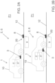
- the invention relates to a method for positioning an electric vehicle 1 on a charging spot 2, the electric vehicle 1 comprising at least one sensor 4, a primary control unit 5 and a chassis 10, the charging spot 2 comprising at least one parking spot 6 including at least one reference element 7, a charging station 20 comprising a charger plug 8 for at least supplying electric energy to the electric vehicle 1 and a secondary control unit 9, the charger plug 8 being able to cooperate with the charging receiver 3 of the electric vehicle 1, method comprising the steps of:
- This method enables to determine with high precision, the best position of the electric vehicle 1 on the parking spot 6, the alignment position P2, i.e. where the charging receiver 3 and the charger plug 8 are perfectly aligned.
- This alignment position P2 being known from the primary control unit 5 of the electric vehicle 1, the electric vehicle 1 can adjust its position to reach this alignment position P2.
- the connection between the charging receiver 3 and the charger plug 8 is easier.
- the method comprises: when the electric vehicle 1 reaches the parking position P1 or initially before starting the parking process, sending data representative of the distance d2, d4, d9 between the at least one reference element 7 and the charger plug 8, from a secondary communication module of the secondary control unit 9 to a primary communication module of the primary control unit 5.
- This data sending enables the primary control unit to determine the reference distance d3, d6, d7 from the data sent by the charging spot 2, which depends on this particular charging spot 2 configuration.
- this method can be used whatever the configuration of the charging spot 2 is.
- the distance d1, d5, d8 between the charging receiver 3 and the at least one point O1, O2, O3 of the chassis 10 can be store in the primary control unit 5 by the electric vehicle 1 manufacturer.
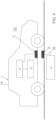
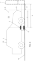
- the at least one sensor 4 of the electric vehicle 1 controlled by the primary control unit 5 measures the actual distance d3, d6, d7 and then sends the actual distance d3, d6, d7 to the primary control unit 5 ( figures 7 , 8 and 9 ).
- This step enables to measure the actual distance d3, d6, d7 by only using the sensor 4 of the electric vehicle 1.
- the sensor 4 of the electric vehicle 1 plays an active role, whereas the reference element 7 only plays a passive role. Consequently, no sensor is required on the reference element 7.
- the electric vehicle 1 is guided and controlled by the primary control unit 5 and the sensor 4 of the electric vehicle 1, which are able to identify the reference element 7 located outside the electric vehicle 1, on the charging spot 2.
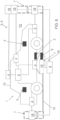
- the at least one sensor 18, 19 of the reference element 7, controlled by the secondary control unit 9 measures the actual distance d3, d6, d7 and then sends the actual distance d3, d6, d7 to the secondary control unit 9, which then sends this distance data to the primary control unit 5 ( figures 8 and 9 ).
- This step enables to measure the actual distance d3, d6, d7 by only using the sensor 18, 19 of the reference element 7 of the charging spot 2.
- the sensor 18, 19 of the reference element 7 plays an active role. Consequently, no sensor is needed on the electric vehicle 1.
- the electric vehicle 1 is guided and controlled by the primary control unit 5, which is in communication with the secondary control unit 9.
- the at least one sensor 4 of the electric vehicle 1 and/or the at least one sensor 18, 19 of the reference element 7 is an ultrasonic sensor emitting an ultrasonic wave and detecting the reflected ultrasonic wave coming from the reference element 7 or coming from the point O1, O2, O3 of the chassis 10.
- the at least one sensor 4 of the electric vehicle 1 and/or the at least one sensor 18, 19 of the reference element 7 is a radar or a lidar emitting electromagnetic waves and detecting the reflected electromagnetic waves coming from the reference element 7 or from the point O1, O2, O3 of the chassis 10.
- the at least one sensor 4 of the electric vehicle 1 and/or the at least one sensor 18, 19 of the reference element 7 is a camera capturing the image of the reference element 7 or of the point O1, O2, O3 of the chassis 10.
- the camera captures the image of the reference element 7 located on the ground 12 of the parking spot 6.
- the at least one sensor 4 of the electric vehicle 1 controlled by the primary control unit 5 is a receiver and the at least one sensor 18, 19 of the reference element 7 is an emitter, the emitter emitting an electromagnetic radiation and the receiver detecting the radiation to measure the actual distance d3, d6 and sends the actual distance d3, d6 to the primary control unit 5.
- This step enables to measure the actual distance d3, d6, d7 by using the sensor 4 of the electric vehicle 1 together with the sensor 18, 19 of the reference element 7 of the charging spot 2.
- the sensor 4 of the electric vehicle 1 and the sensor 18, 19 of the reference element 7 play active roles.
- the electric vehicle 1 is guided and controlled by the primary control unit 5 and the sensor 4 of the electric vehicle 1, which are able to cooperate with the sensor 18, 19 of the reference element 7 located outside the electric vehicle 1 on the charging spot 2.
- the emitter is an infrared emitter and the receiver is an infrared receiver.
- the primary control unit 5 when comparing the actual distance d3, d6, d7 and the predetermined reference distance d3, d6, d7, if the actual distance d3, d6, d7 is equal to the predetermined reference distance d3, d6, d7 then the primary control unit 5 sends an order to the electric vehicle 1 to stop the electric vehicle 1.
- This step enables to determine if the electric vehicle 1 is in the alignment position P2. Thus, the electric vehicle 1 stops and a charging session can start on the charging spot 2.
- the primary control unit 5 sends an order to the electric vehicle 1 to move the electric vehicle 1 to adjust the actual distance d3, d6, d7 and reach the alignment position P2.
- This step enables to adjust the electric vehicle 1 position while the electric vehicle 1 is not in the alignment position P2.
- the at least one sensor 4 of the electric vehicle 1, controlled by the primary control unit 5 detects a marking element 11 located on the ground 12 of the parking spot 6 for automatically positioning the electric vehicle 1 on the parking spot 6 ( figure 1 ).
- This step enables the automatic guidance of the electric vehicle toward the parking spot 6.
- the method further comprises a charging session step, where the charger plug 8 and the charging receiver 3 are connected together, and electric energy is supplied to a battery 5" of the electric vehicle 1.
- the primary control unit 5 of the electric vehicle 1 comprises the primary communication module.
- This primary control unit is provided to communicate with the secondary communication module of the secondary control unit 9 of the charging station 20, preferably wirelessly.
- These primary and secondary communication modules are provided to exchange data between the charging spot 2 and the electric vehicle 1.
- the secondary communication module can send data representative of the distance d2, d4, d9 to the primary communication module of the primary control unit 5.
- the primary control unit 5 can collect these data and determine the reference distance d3, d6, d7.
- the primary control unit 5 of the electric vehicle 1 is also electrically connected to the sensor 4 of the electric vehicle 1.
- the primary control unit 5 is also suitable and provided to control the sensor 4 of the electric vehicle 1 and to collect the data of the sensor 4, which are representative of the actual distance d3, d6, d7.
- the secondary control unit 9 is suitable and provided to control the sensor 18, 19 of the reference element 7 and to collect the data of the sensor 18, 19, which are representative of the actual distance d3, d6, d7.
- the secondary control unit 9 is also suitable and provided to send these data to the primary control unit 5 by means of the primary and secondary communication modules.
- the primary control unit 5 is also suitable and provided to compare the data, which are representative of the actual distance d3, d6, d7 with the reference distance d3, d6, d7.
- the primary control unit 5 is also suitable and provided to automatically move the electric vehicle 1.
- the electric vehicle 1 comprises the battery 5" electrically connected to the charging receiver 3 of the electric vehicle 1.
- the battery 5" and the charging receiver 3 are preferably controlled by an electronic unit 5'.
- This electronic unit 5' can be electrically connected to the primary control unit 5 of the electric vehicle 1.
- this electronic unit 5' could be an on board charger, which comprises a rectifier (not shown), which converts an alternating current (AC) current in direct current (DC), which is required to charge the battery 5".
- This rectifier is required if the charger plug 8 supplies alternating current (AC) to the charging receiver 3.
- the electronic unit 5' comprises a protection device and/or a switch, like a contactor (not shown), to open or close a circuit between the charging receiver 3 and battery 5".
- the invention also relates to a charging spot 2 comprising at least one parking spot 6 and a charging station 20 comprising a charger plug 8 for at least supplying electric energy to the electric vehicle 1, wherein the parking spot 6 comprises at least one reference element 7.
- This reference element 7 is provided to be identified by the sensor 4 of the electric vehicle 1 and/or to identify the electric vehicle 1.
- This charging spot 2 is provided to enable the implementation of the method according to the present invention.
- the at least one reference element 7 is located on the ground 12 of the parking spot 6 ( figures 8 and 9 ), and/or on a wall 13 ( figures 6 , 7 and 8 ) and/or a barrier 14 ( figures 6 , 7 and 8 ) surrounding the parking spot 6.
- the charging spot 2 comprises a secondary control unit 9 comprising a secondary communication module to communicate with a primary communication module of the primary control unit of the electric vehicle 1.
- the primary communication module and secondary communication module could be any kind of wireless communication means, for instance: a Bluetooth unit or a RFID unit or a NFC unit or a Wi-Fi unit.
- the at least one reference element 7 comprises at least one sensor 18, 19 ( figures 8 and 9 ).
- This sensor 18, 19 is provided to identify the electric vehicle 1 and to measure the actual distance d3, d6, d7.
- the secondary control unit 9 is provided to control the sensor 18, 19.
- the secondary control unit 9 is located on the charging station 20 and is electrically connected to the sensor 18, 19.
- the charging station 20 is located on the ground 12 and comprises the reference element 7 arranged in the vicinity of the charger plug 8, the reference element 7 comprising at least one sensor 19 ( figures 8 and 9 ).
- the at least one sensor 18, 19 of the reference element 7 is selected from the group comprising: an ultrasonic sensor, a radar, a lidar, a camera, an infrared emitter, an infrared receiver.
- a marking element 11 is located on the ground 12 of the parking spot 6 ( figure 1 ).
- the marking element 11 is provided to be identified by the sensor 4 of the electric vehicle 1 controlled by the primary control unit 5.
- the electric vehicle 1 can be automatically positioned on the parking spot 6.
- the sensor 4, which is used preferably is a camera.
- the marking element 11 can be a line on the ground 12.
- the charging station 20 comprises at least a power supply system (not shown) to provide electric energy.
- the charging station 20 comprises at least a supply cable (not shown) electrically connected to the charger plug 8 and to the power supply system.
- the charging station 20 comprises a cooling system (not shown) to maintain the battery 5" of the electric vehicle 1within an acceptable temperature range during a charging session.
- a cooling system (not shown) to maintain the battery 5" of the electric vehicle 1within an acceptable temperature range during a charging session.
- the charging station 20 comprises fluid lines (not shown) connected to the charger plug 2 and to the cooling system.
- the charging station 20 is located on the ground 12 of the parking spot 6.
- the power supply and/or the cooling system are controlled by the secondary control unit 9.
- Another object relates to an alternative method for positioning an electric vehicle 1 on a charging spot 2 which is not according to the invention, the charging spot 2 comprising at least one parking spot 6 including at least one wheel chock 15 comprising a sensor 16 and a charging station 20 comprising a charger plug 8 for at least supplying electric energy to the electric vehicle 1, the charger plug 8 being able to cooperate with the charging receiver 3 of the electric vehicle 1 ( figure 10 ), method comprising:
- the distance d10 between the axis of the front wheels 17 and the charging receiver 3, as well as the distance d11 between the wheel chock 15 and the charger plug 8 are standard distances, and these distances d10, d11 are equal. Therefore, the charger plug 8 could be electrically easily connected to the charging receiver 3, as the charger plug 8 and the charging receiver 3 are aligned, when the sensor 16 has detected that the front wheels 17 are locked by the wheel chock 15.
- these distances d10, d11 are not necessarily equal.
- the method includes the further steps of:
- the charger plug 8 could be moved by means of an actuator knowing the distance d10 and the distance d11 and then be electrically connected to the charging receiver 3.
- the method preferably includes the step of sending the distance d10 from a primary communication module of the primary control unit 5 to a secondary communication module of the secondary control unit 9.
- a charging spot 2 which is not according to the invention comprises at least one parking spot 6 and a charging station 20 comprising a charger plug 8 for at least supplying electric energy to an electric vehicle 1, wherein the parking spot 6 comprises at least one wheel chock 15 fixed to the ground 12 of the parking spot 6 ( figure 10 ), the wheel chock 15 and the charger plug 8 of the charging station 20 being separated from one to another by a distance d11
- This charging spot 2 is provided to enable the implementation of this alternative method according to the other object which is not according to the present invention.
- the wheel chock 15 is a groove located on the ground 12 of the parking spot 6 ( figure 10 ).
- the charging station 20 is located on the ground 12 of the parking spot 6 ( figure 10 ).
- the charger plug 8 is mounted on an actuator located on the ground 12, like for instance an arm (not shown) or a scissor lift (not shown) to move the charger plug 8 toward the charging receiver 3 in translation and/or in rotation.
- an actuator located on the ground 12, like for instance an arm (not shown) or a scissor lift (not shown) to move the charger plug 8 toward the charging receiver 3 in translation and/or in rotation.
- the charging station 20 comprises the secondary control unit 9.
- This secondary control unit 9 comprises a secondary communication module.
- the primary communication module and secondary communication module could be any kind of wireless communication means, for instance: a Bluetooth unit or a RFID unit or a NFC unit or a Wi-Fi unit.
- the wheel chock 15 comprises a sensor 16.
- This sensor 16 could be an optical sensor or a weight sensor.
Landscapes
- Engineering & Computer Science (AREA)
- Physics & Mathematics (AREA)
- Radar, Positioning & Navigation (AREA)
- Remote Sensing (AREA)
- General Physics & Mathematics (AREA)
- Aviation & Aerospace Engineering (AREA)
- Automation & Control Theory (AREA)
- Power Engineering (AREA)
- Mechanical Engineering (AREA)
- Transportation (AREA)
- Electromagnetism (AREA)
- Optics & Photonics (AREA)
- Computer Networks & Wireless Communication (AREA)
- Acoustics & Sound (AREA)
- Computer Vision & Pattern Recognition (AREA)
- Multimedia (AREA)
- Charge And Discharge Circuits For Batteries Or The Like (AREA)
- Electric Propulsion And Braking For Vehicles (AREA)
Claims (13)
- Verfahren zum Positionieren eines Elektrofahrzeugs (1) auf einer Ladestelle (2), wobei das Elektrofahrzeug (1) mindestens einen Sensor (4), eine primäre Steuereinheit (5) und ein Fahrgestell (10) umfasst, wobei die Ladestelle (2) mindestens eine Parkstelle (6), die mindestens ein Referenzelement (7) beinhaltet, eine Ladestation (20), die einen Ladestecker (8) mindestens zum Zuführen von elektrischer Energie zum Elektrofahrzeug (1) umfasst, und eine sekundäre Steuereinheit (9) umfasst, wobei der Ladestecker (8) in der Lage ist, mit dem Ladeempfänger (3) des Elektrofahrzeugs (1) zusammenzuwirken, wobei das Verfahren die folgenden Schritte umfasst:Bewegen des Elektrofahrzeugs (1) zur Parkstelle (6), um eine Parkposition (P1) zu erreichen,Bestimmen einer Ausrichtungsposition (P2) des Elektrofahrzeugs (1), in der der Ladeempfänger (3) und der Ladestecker (8) ausgerichtet sind, durch Bestimmen eines Referenzabstands (d3, d6, d7) zwischen mindestens einem Punkt (01, O2, O3) des Fahrgestells (10) und dem mindestens einen Referenzelement (7) mittels der primären Steuereinheit (5) des Elektrofahrzeugs (1), Kennen des Abstands (d1, d5, d8) zwischen dem Ladeempfänger (3) und dem mindestens einen Punkt (01, O2, O3) des Fahrgestells (10) und Kennen des Abstands (d2, d4, d9) zwischen dem mindestens einen Referenzelement (7) und dem Ladestecker (8),Bewegen des Elektrofahrzeugs (1) auf der Parkstelle (6) von der Parkposition (P1) zur Ausrichtungsposition (P2) durch Geführt- und Gesteuertwerden mittels des mindestens einen Sensors (4) des Elektrofahrzeugs (1) und mindestens eines Sensors (18, 19) des Referenzelements (7), der den tatsächlichen Abstand (d3, d6, d7) zwischen dem mindestens einen Punkt (01, O2, O3) des Fahrgestells (10) und dem mindestens einen Referenzelement (7) misst, und mittels der primären Steuereinheit (5), die den tatsächlichen Abstand (d3, d6, d7) und den vorbestimmten Referenzabstand (d3, d6, d7) vergleicht, zum Parken des Elektrofahrzeugs (1) in dem vorbestimmten Referenzabstand (d3, d6, d7) vom Referenzelement (7), derart, dass der Ladeempfänger (3) des Elektrofahrzeugs (1) und der Ladestecker (8) der Ladestelle (2) ausgerichtet sind,dadurch gekennzeichnet, dass das Verfahren Folgendes umfasst: wenn das Elektrofahrzeug (1) die Parkposition (P1) erreicht, oder anfänglich vor Starten des Parkprozesses Senden von Daten, die für den Abstand (d2, d4, d9) zwischen dem mindestens einen Referenzelement (7) und dem Ladestecker (8) repräsentativ sind, von einem sekundären Kommunikationsmodul der sekundären Steuereinheit (9) an ein primäres Kommunikationsmodul der primären Steuereinheit (5), wobei die primäre Steuereinheit (5) diese Daten sammelt, um den Referenzabstand (d3, d6, d7) zu bestimmen, wobei, wenn das Elektrofahrzeug (1) auf der Parkstelle (6) von der Parkposition (P1) zur Ausrichtungsposition (P2) bewegt wird, der mindestens eine Sensor (18, 19) des Referenzelements (7), der von der sekundären Steuereinheit (9) gesteuert wird, den tatsächlichen Abstand (d3, d6, d7) misst und dann den tatsächlichen Abstand (d3, d6, d7) an die sekundäre Steuereinheit (9) sendet, die diese Abstandsdaten dann an die primäre Steuereinheit (5) sendet,der Ladestecker (8) ist an einem Aktuator montiert, der sich auf dem Boden (12) befindet, um den Ladestecker (8) durch Versetzen und/oder durch Drehen zum Ladeempfänger (3) zu bewegen,und wenn sich das Elektrofahrzeug (1) in der Ausrichtungsposition (P2) befindet, umfasst das Verfahren ferner einen Ladesitzungsschritt, in dem der Ladestecker (8) und der Ladeempfänger (3) elektrisch verbunden werden und einer Batterie (5") des Elektrofahrzeugs (1) elektrische Energie zugeführt wird.
- Verfahren nach Anspruch 1, wobei der mindestens eine Sensor (4) des Elektrofahrzeugs (1) und/oder der mindestens eine Sensor (18, 19) des Referenzelements (7) ein Ultraschallsensor ist, der eine Ultraschallwelle emittiert und die reflektierte Ultraschallwelle, die vom Referenzelement (7) kommt oder von dem Punkt (01, O2, O3) des Fahrgestells (10) kommt, detektiert.
- Verfahren nach einem der Ansprüche 1 bis 2, wobei der mindestens eine Sensor (4) des Elektrofahrzeugs (1) und/oder der mindestens eine Sensor (18, 19) des Referenzelements (7) ein Radar oder ein Lidar ist, das elektromagnetische Wellen emittiert und die reflektierten elektromagnetischen Wellen, die vom Referenzelement (7) oder von dem Punkt (01, O2, O3) des Fahrgestells (10) kommen, detektiert.
- Verfahren nach einem der Ansprüche 1 bis 3, wobei der mindestens eine Sensor (4) des Elektrofahrzeugs (1) und/oder der mindestens eine Sensor (18, 19) des Referenzelements (7) eine Kamera ist, die das Bild des Referenzelements (7) oder des Punkts (01, O2, O3) des Fahrgestells (10) erfasst.
- Verfahren nach Anspruch 4, wobei die Kamera das Bild des Referenzelements (7), das sich auf dem Boden (12) der Parkstelle (6) befindet, erfasst.
- Verfahren nach einem der Ansprüche 1 bis 5, wobei, wenn der tatsächliche Abstand (d3, d6, d7) mit dem vorbestimmten Referenzabstand (d3, d6, d7) verglichen wird und der tatsächliche Abstand (d3, d6, d7) gleich dem vorbestimmten Referenzabstand (d3, d6, d7) ist, die primäre Steuereinheit (5) einen Befehl zum Stoppen des Elektrofahrzeugs (1) an das Elektrofahrzeug (1) sendet.
- Verfahren nach einem der Ansprüche 1 bis 5, wobei, wenn der tatsächliche Abstand (d3, d6, d7) mit dem vorbestimmten Referenzabstand (d3, d6, d7) verglichen wird und sich der tatsächliche Abstand (d3, d6, d7) vom vorbestimmten Referenzabstand (d3, d6, d7) unterscheidet, die primäre Steuereinheit (5) einen Befehl zum Bewegen des Elektrofahrzeugs (1) an das Elektrofahrzeug (1) sendet, um den tatsächlichen Abstand (d3, d6, d7) anzupassen und die Ausrichtungsposition (P2) zu erreichen.
- Verfahren nach einem der Ansprüche 1 bis 7, wobei, wenn zuerst das Elektrofahrzeug (1) bewegt wird, um die Parkposition (P1) zu erreichen, der mindestens eine Sensor (4) des Elektrofahrzeugs (1), der von der primären Steuereinheit (5) gesteuert wird, ein Markierungselement (11) detektiert, das sich auf dem Boden (12) der Parkstelle (6) befindet, um das Elektrofahrzeug (1) automatisch auf der Parkstelle (6) zu positionieren.
- Ladestelle (2), die dazu ausgelegt ist, die Implementierung des Verfahrens nach einem der Ansprüche 1 bis 8 zu ermöglichen, und mindestens eine Parkstelle (6) und eine Ladestation (20) umfasst, die einen Ladestecker (8) umfasst, der geeignet ist, einem Elektrofahrzeug (1) elektrische Energie zuzuführen, das mindestens einen Sensor (4), eine primäre Steuereinheit (5), einen Ladeempfänger (3) und ein Fahrgestell (10) umfasst, wobei die Parkstelle (6) mindestens ein Referenzelement (7) umfasst und der Ladestecker (8) an einem Aktuator montiert ist, der sich auf dem Boden (12) befindet, um den Ladestecker (8) durch Versetzen und/oder durch Drehen zum Ladeempfänger (3) zu bewegen, und wobei das mindestens eine Referenzelement (7) mindestens einen Sensor (18, 19) umfasst, der bereitgestellt ist, um das Elektrofahrzeug (1) zu identifizieren und den tatsächlichen Abstand (d3, d6, d7) zwischen dem mindestens einen Punkt (01, O2, O3) des Fahrgestells (10) und dem mindestens einen Referenzelement (7) zu messen.
- Ladestelle nach Anspruch 9, wobei sich das mindestens eine Referenzelement (7) auf dem Boden (12) der Parkstelle (6) und/oder an einer Wand (13) und/oder einer Absperrung (14), die die Parkstelle (6) umgibt, befindet.
- Ladestelle nach einem der Ansprüche 9 bis 10, wobei sich die Ladestation (20) auf dem Boden (12) befindet.
- Ladestelle nach einem der Ansprüche 9 bis 11, wobei der mindestens eine Sensor (18, 19) des Referenzelements (7) aus der Gruppe ausgewählt wird, die Folgendes umfasst: einen Ultraschallsensor, ein Radar, ein Lidar, eine Kamera, einen Infrarotemitter, einen Infrarotempfänger.
- Ladestellen nach einem der Ansprüche 9 bis 12, wobei sich auf dem Boden (12) der Parkstelle (6) ein Markierungselement (11) befindet, wobei das Markierungselement bereitgestellt ist, um vom Sensor (4) des Elektrofahrzeugs (1), der von der primären Steuereinheit (5) gesteuert wird, identifiziert zu werden.
Priority Applications (3)
| Application Number | Priority Date | Filing Date | Title |
|---|---|---|---|
| EP18305425.3A EP3552861B1 (de) | 2018-04-10 | 2018-04-10 | Verfahren zur positionierung eines elektrischen fahrzeugs auf einer ladestelle und zugehörige ladestelle |
| AU2019202456A AU2019202456A1 (en) | 2018-04-10 | 2019-04-09 | Method for positioning an electric vehicle on a charging spot and related charging spot |
| CN201910283444.3A CN110356276A (zh) | 2018-04-10 | 2019-04-09 | 用于将电动车辆定位在充电桩上的方法及相关的充电桩 |
Applications Claiming Priority (1)
| Application Number | Priority Date | Filing Date | Title |
|---|---|---|---|
| EP18305425.3A EP3552861B1 (de) | 2018-04-10 | 2018-04-10 | Verfahren zur positionierung eines elektrischen fahrzeugs auf einer ladestelle und zugehörige ladestelle |
Publications (2)
| Publication Number | Publication Date |
|---|---|
| EP3552861A1 EP3552861A1 (de) | 2019-10-16 |
| EP3552861B1 true EP3552861B1 (de) | 2023-11-29 |
Family
ID=61972470
Family Applications (1)
| Application Number | Title | Priority Date | Filing Date |
|---|---|---|---|
| EP18305425.3A Active EP3552861B1 (de) | 2018-04-10 | 2018-04-10 | Verfahren zur positionierung eines elektrischen fahrzeugs auf einer ladestelle und zugehörige ladestelle |
Country Status (3)
| Country | Link |
|---|---|
| EP (1) | EP3552861B1 (de) |
| CN (1) | CN110356276A (de) |
| AU (1) | AU2019202456A1 (de) |
Cited By (1)
| Publication number | Priority date | Publication date | Assignee | Title |
|---|---|---|---|---|
| FR3159569A1 (fr) * | 2024-02-22 | 2025-08-29 | Stellantis Auto Sas | Procede d’alignement d’un recepteur de charge d’un vehicule automobile electrique ou hybride et d’une base emettrice d’une station de rechargement |
Families Citing this family (4)
| Publication number | Priority date | Publication date | Assignee | Title |
|---|---|---|---|---|
| DE102019130820A1 (de) | 2019-11-14 | 2021-05-20 | Webasto SE | Verfahren und ein System zum Laden einer Batterie eines Elektrofahrzeugs |
| DE102020123216B4 (de) * | 2020-09-04 | 2022-09-15 | Juice Technology AG | Ladestecker, Ladegerät und Verfahren zum Aufladen eines Elektrofahrzeugs |
| US11427102B2 (en) * | 2020-10-28 | 2022-08-30 | GM Global Technology Operations LLC | System and method of autonomously charging an electric vehicle |
| CN112644310B (zh) * | 2020-12-25 | 2022-12-30 | 东风汽车有限公司 | 电动汽车充电控制方法、电子设备、充电桩充电控制方法及充电桩 |
Citations (6)
| Publication number | Priority date | Publication date | Assignee | Title |
|---|---|---|---|---|
| CH688598A5 (de) * | 1993-10-05 | 1997-11-28 | Ernst Erb | Zapf-Parkplatz fuer Elektromobile. |
| WO2010098412A1 (ja) * | 2009-02-25 | 2010-09-02 | マスプロ電工株式会社 | 移動体の電力供給システム |
| US20100235006A1 (en) * | 2009-03-12 | 2010-09-16 | Wendell Brown | Method and Apparatus for Automatic Charging of an Electrically Powered Vehicle |
| US20110066515A1 (en) * | 2009-09-16 | 2011-03-17 | Horvath Ronald F | Automated electric plug-in station for charging electric and hybrid vehicles |
| WO2013136787A1 (ja) * | 2012-03-14 | 2013-09-19 | パナソニック株式会社 | 給電装置、受電装置及び給電システム |
| EP3092147A1 (de) * | 2014-01-10 | 2016-11-16 | Robert Bosch GmbH | Elektrische ladevorrichtung, elektrische anschlussvorrichtung, system und verfahren zum laden einer batterie eines fahrzeugs |
Family Cites Families (6)
| Publication number | Priority date | Publication date | Assignee | Title |
|---|---|---|---|---|
| WO2014199499A1 (ja) * | 2013-06-13 | 2014-12-18 | 株式会社Ihi | 車両給電システム |
| GB2523186B (en) * | 2014-02-18 | 2020-03-25 | Ford Global Tech Llc | Vehicle control system for aligning inductive charging connection |
| US9527403B2 (en) | 2014-04-29 | 2016-12-27 | Tesla Motors, Inc. | Charging station providing thermal conditioning of electric vehicle during charging session |
| DE102014213195A1 (de) * | 2014-07-08 | 2016-01-14 | Robert Bosch Gmbh | Vorrichtung und Verfahren zum Betreiben eines induktiven Ladesystems |
| CN105818703A (zh) * | 2016-03-25 | 2016-08-03 | 乐视控股(北京)有限公司 | 充电桩控制系统、多功能充电桩和电动车辆 |
| KR102489386B1 (ko) * | 2016-04-15 | 2023-01-18 | 주식회사 에이치엘클레무브 | 주차 지원 장치 및 그의 주차 제어 방법 |
-
2018
- 2018-04-10 EP EP18305425.3A patent/EP3552861B1/de active Active
-
2019
- 2019-04-09 CN CN201910283444.3A patent/CN110356276A/zh active Pending
- 2019-04-09 AU AU2019202456A patent/AU2019202456A1/en not_active Abandoned
Patent Citations (6)
| Publication number | Priority date | Publication date | Assignee | Title |
|---|---|---|---|---|
| CH688598A5 (de) * | 1993-10-05 | 1997-11-28 | Ernst Erb | Zapf-Parkplatz fuer Elektromobile. |
| WO2010098412A1 (ja) * | 2009-02-25 | 2010-09-02 | マスプロ電工株式会社 | 移動体の電力供給システム |
| US20100235006A1 (en) * | 2009-03-12 | 2010-09-16 | Wendell Brown | Method and Apparatus for Automatic Charging of an Electrically Powered Vehicle |
| US20110066515A1 (en) * | 2009-09-16 | 2011-03-17 | Horvath Ronald F | Automated electric plug-in station for charging electric and hybrid vehicles |
| WO2013136787A1 (ja) * | 2012-03-14 | 2013-09-19 | パナソニック株式会社 | 給電装置、受電装置及び給電システム |
| EP3092147A1 (de) * | 2014-01-10 | 2016-11-16 | Robert Bosch GmbH | Elektrische ladevorrichtung, elektrische anschlussvorrichtung, system und verfahren zum laden einer batterie eines fahrzeugs |
Non-Patent Citations (2)
| Title |
|---|
| CAR TV: "Volkswagen E-smart Connect", YOUTUBE, 14 July 2015 (2015-07-14), pages 1 pp., XP054976835, Retrieved from the Internet <URL:https://www.youtube.com/watch?v=-9VulKSy5uw> [retrieved on 20161012] * |
| TESLA: "Charger prototype finding its way to Model S", YOUTUBE, 6 August 2015 (2015-08-06), pages 1 pp., XP054976837, Retrieved from the Internet <URL:https://www.youtube.com/watch?v=uMM0lRfX6YI> [retrieved on 20161012] * |
Cited By (1)
| Publication number | Priority date | Publication date | Assignee | Title |
|---|---|---|---|---|
| FR3159569A1 (fr) * | 2024-02-22 | 2025-08-29 | Stellantis Auto Sas | Procede d’alignement d’un recepteur de charge d’un vehicule automobile electrique ou hybride et d’une base emettrice d’une station de rechargement |
Also Published As
| Publication number | Publication date |
|---|---|
| EP3552861A1 (de) | 2019-10-16 |
| AU2019202456A1 (en) | 2019-10-24 |
| CN110356276A (zh) | 2019-10-22 |
Similar Documents
| Publication | Publication Date | Title |
|---|---|---|
| EP3552861B1 (de) | Verfahren zur positionierung eines elektrischen fahrzeugs auf einer ladestelle und zugehörige ladestelle | |
| CN107000605B (zh) | 用于给车辆中的电蓄能器自动充电的充电站和方法 | |
| US12122332B2 (en) | Systems and methods for automated in-situ swapping of batteries for electric vehicles | |
| CN105691218B (zh) | 确定充电站的充电装置的充电位置 | |
| US9770993B2 (en) | Electric vehicle charging station | |
| US9327607B2 (en) | Automated recharging system and method for an electric vehicle using RFID tags | |
| US20250187461A1 (en) | Method for controlling power transmitting device, method for detecting foreign object, and power transmitting device in wireless power transmission system | |
| EP3722164B1 (de) | Batterieaustauschsystem | |
| KR101725703B1 (ko) | 비접촉 급전 시스템 | |
| KR101735233B1 (ko) | 비접촉 급전 시스템 및 급전 장치 | |
| US9421874B2 (en) | Connecting apparatus for connecting an electrically powered vehicle to a charging station | |
| US10052963B2 (en) | Contactless power transfer system and method of controlling the same | |
| GB2500691A (en) | Charging system for a vehicle | |
| EP2717428B1 (de) | Kontaktlose stromversorgungsvorrichtung, fahrzeug und kontaktloses stromversorgungssystem | |
| KR101689495B1 (ko) | 비접촉 급전 시스템 | |
| CN111287526B (zh) | 机动车的停车机械手系统以及运行停车机械手系统的方法 | |
| JP2010226945A (ja) | 移動体の電力供給システム | |
| KR20150119389A (ko) | 비접촉 급전 시스템 | |
| WO2015075858A1 (en) | Contactless power transmitting device and contactless power transfer system | |
| KR20230065473A (ko) | 무선 충전 상황을 안내하는 전기 이동체 및 이를 이용한 방법 | |
| US20250256592A1 (en) | Method and system for automatic electrical connection between two connectors | |
| JP2016211210A (ja) | 駐車設備システム | |
| US9929600B2 (en) | Wireless power supply system and wireless power reception device | |
| EP2981432B1 (de) | Verbindungsvorrichtung zum verbinden eines elektrisch angetrienen fahrzeugs mit einer ladestation | |
| US20230202325A1 (en) | Microscopic alignment method for wireless charging of electric vehicle and apparatus and system therefor |
Legal Events
| Date | Code | Title | Description |
|---|---|---|---|
| PUAI | Public reference made under article 153(3) epc to a published international application that has entered the european phase |
Free format text: ORIGINAL CODE: 0009012 |
|
| STAA | Information on the status of an ep patent application or granted ep patent |
Free format text: STATUS: THE APPLICATION HAS BEEN PUBLISHED |
|
| AK | Designated contracting states |
Kind code of ref document: A1 Designated state(s): AL AT BE BG CH CY CZ DE DK EE ES FI FR GB GR HR HU IE IS IT LI LT LU LV MC MK MT NL NO PL PT RO RS SE SI SK SM TR |
|
| AX | Request for extension of the european patent |
Extension state: BA ME |
|
| STAA | Information on the status of an ep patent application or granted ep patent |
Free format text: STATUS: REQUEST FOR EXAMINATION WAS MADE |
|
| 17P | Request for examination filed |
Effective date: 20200415 |
|
| RBV | Designated contracting states (corrected) |
Designated state(s): AL AT BE BG CH CY CZ DE DK EE ES FI FR GB GR HR HU IE IS IT LI LT LU LV MC MK MT NL NO PL PT RO RS SE SI SK SM TR |
|
| STAA | Information on the status of an ep patent application or granted ep patent |
Free format text: STATUS: EXAMINATION IS IN PROGRESS |
|
| 17Q | First examination report despatched |
Effective date: 20200828 |
|
| REG | Reference to a national code |
Ref country code: DE Ref legal event code: R079 Free format text: PREVIOUS MAIN CLASS: B60L0011180000 Ipc: H02J0050900000 Ref country code: DE Ref legal event code: R079 Ref document number: 602018061763 Country of ref document: DE Free format text: PREVIOUS MAIN CLASS: B60L0011180000 Ipc: H02J0050900000 |
|
| RIC1 | Information provided on ipc code assigned before grant |
Ipc: B60L 53/66 20190101ALI20230503BHEP Ipc: G05D 1/02 20060101ALI20230503BHEP Ipc: H02J 50/90 20160101AFI20230503BHEP |
|
| GRAP | Despatch of communication of intention to grant a patent |
Free format text: ORIGINAL CODE: EPIDOSNIGR1 |
|
| STAA | Information on the status of an ep patent application or granted ep patent |
Free format text: STATUS: GRANT OF PATENT IS INTENDED |
|
| INTG | Intention to grant announced |
Effective date: 20230616 |
|
| P01 | Opt-out of the competence of the unified patent court (upc) registered |
Effective date: 20230606 |
|
| GRAS | Grant fee paid |
Free format text: ORIGINAL CODE: EPIDOSNIGR3 |
|
| GRAA | (expected) grant |
Free format text: ORIGINAL CODE: 0009210 |
|
| STAA | Information on the status of an ep patent application or granted ep patent |
Free format text: STATUS: THE PATENT HAS BEEN GRANTED |
|
| AK | Designated contracting states |
Kind code of ref document: B1 Designated state(s): AL AT BE BG CH CY CZ DE DK EE ES FI FR GB GR HR HU IE IS IT LI LT LU LV MC MK MT NL NO PL PT RO RS SE SI SK SM TR |
|
| REG | Reference to a national code |
Ref country code: GB Ref legal event code: FG4D |
|
| REG | Reference to a national code |
Ref country code: CH Ref legal event code: EP |
|
| REG | Reference to a national code |
Ref country code: DE Ref legal event code: R096 Ref document number: 602018061763 Country of ref document: DE |
|
| REG | Reference to a national code |
Ref country code: IE Ref legal event code: FG4D |
|
| REG | Reference to a national code |
Ref country code: NL Ref legal event code: FP |
|
| REG | Reference to a national code |
Ref country code: LT Ref legal event code: MG9D |
|
| PG25 | Lapsed in a contracting state [announced via postgrant information from national office to epo] |
Ref country code: GR Free format text: LAPSE BECAUSE OF FAILURE TO SUBMIT A TRANSLATION OF THE DESCRIPTION OR TO PAY THE FEE WITHIN THE PRESCRIBED TIME-LIMIT Effective date: 20240301 |
|
| PG25 | Lapsed in a contracting state [announced via postgrant information from national office to epo] |
Ref country code: IS Free format text: LAPSE BECAUSE OF FAILURE TO SUBMIT A TRANSLATION OF THE DESCRIPTION OR TO PAY THE FEE WITHIN THE PRESCRIBED TIME-LIMIT Effective date: 20240329 |
|
| PG25 | Lapsed in a contracting state [announced via postgrant information from national office to epo] |
Ref country code: LT Free format text: LAPSE BECAUSE OF FAILURE TO SUBMIT A TRANSLATION OF THE DESCRIPTION OR TO PAY THE FEE WITHIN THE PRESCRIBED TIME-LIMIT Effective date: 20231129 |
|
| PG25 | Lapsed in a contracting state [announced via postgrant information from national office to epo] |
Ref country code: ES Free format text: LAPSE BECAUSE OF FAILURE TO SUBMIT A TRANSLATION OF THE DESCRIPTION OR TO PAY THE FEE WITHIN THE PRESCRIBED TIME-LIMIT Effective date: 20231129 |
|
| PG25 | Lapsed in a contracting state [announced via postgrant information from national office to epo] |
Ref country code: LT Free format text: LAPSE BECAUSE OF FAILURE TO SUBMIT A TRANSLATION OF THE DESCRIPTION OR TO PAY THE FEE WITHIN THE PRESCRIBED TIME-LIMIT Effective date: 20231129 Ref country code: IS Free format text: LAPSE BECAUSE OF FAILURE TO SUBMIT A TRANSLATION OF THE DESCRIPTION OR TO PAY THE FEE WITHIN THE PRESCRIBED TIME-LIMIT Effective date: 20240329 Ref country code: GR Free format text: LAPSE BECAUSE OF FAILURE TO SUBMIT A TRANSLATION OF THE DESCRIPTION OR TO PAY THE FEE WITHIN THE PRESCRIBED TIME-LIMIT Effective date: 20240301 Ref country code: ES Free format text: LAPSE BECAUSE OF FAILURE TO SUBMIT A TRANSLATION OF THE DESCRIPTION OR TO PAY THE FEE WITHIN THE PRESCRIBED TIME-LIMIT Effective date: 20231129 Ref country code: BG Free format text: LAPSE BECAUSE OF FAILURE TO SUBMIT A TRANSLATION OF THE DESCRIPTION OR TO PAY THE FEE WITHIN THE PRESCRIBED TIME-LIMIT Effective date: 20240229 |
|
| PG25 | Lapsed in a contracting state [announced via postgrant information from national office to epo] |
Ref country code: SE Free format text: LAPSE BECAUSE OF FAILURE TO SUBMIT A TRANSLATION OF THE DESCRIPTION OR TO PAY THE FEE WITHIN THE PRESCRIBED TIME-LIMIT Effective date: 20231129 Ref country code: RS Free format text: LAPSE BECAUSE OF FAILURE TO SUBMIT A TRANSLATION OF THE DESCRIPTION OR TO PAY THE FEE WITHIN THE PRESCRIBED TIME-LIMIT Effective date: 20231129 Ref country code: PL Free format text: LAPSE BECAUSE OF FAILURE TO SUBMIT A TRANSLATION OF THE DESCRIPTION OR TO PAY THE FEE WITHIN THE PRESCRIBED TIME-LIMIT Effective date: 20231129 Ref country code: NO Free format text: LAPSE BECAUSE OF FAILURE TO SUBMIT A TRANSLATION OF THE DESCRIPTION OR TO PAY THE FEE WITHIN THE PRESCRIBED TIME-LIMIT Effective date: 20240229 Ref country code: LV Free format text: LAPSE BECAUSE OF FAILURE TO SUBMIT A TRANSLATION OF THE DESCRIPTION OR TO PAY THE FEE WITHIN THE PRESCRIBED TIME-LIMIT Effective date: 20231129 Ref country code: HR Free format text: LAPSE BECAUSE OF FAILURE TO SUBMIT A TRANSLATION OF THE DESCRIPTION OR TO PAY THE FEE WITHIN THE PRESCRIBED TIME-LIMIT Effective date: 20231129 |
|
| PG25 | Lapsed in a contracting state [announced via postgrant information from national office to epo] |
Ref country code: DK Free format text: LAPSE BECAUSE OF FAILURE TO SUBMIT A TRANSLATION OF THE DESCRIPTION OR TO PAY THE FEE WITHIN THE PRESCRIBED TIME-LIMIT Effective date: 20231129 |
|
| PG25 | Lapsed in a contracting state [announced via postgrant information from national office to epo] |
Ref country code: CZ Free format text: LAPSE BECAUSE OF FAILURE TO SUBMIT A TRANSLATION OF THE DESCRIPTION OR TO PAY THE FEE WITHIN THE PRESCRIBED TIME-LIMIT Effective date: 20231129 |
|
| PG25 | Lapsed in a contracting state [announced via postgrant information from national office to epo] |
Ref country code: SK Free format text: LAPSE BECAUSE OF FAILURE TO SUBMIT A TRANSLATION OF THE DESCRIPTION OR TO PAY THE FEE WITHIN THE PRESCRIBED TIME-LIMIT Effective date: 20231129 |
|
| PG25 | Lapsed in a contracting state [announced via postgrant information from national office to epo] |
Ref country code: SM Free format text: LAPSE BECAUSE OF FAILURE TO SUBMIT A TRANSLATION OF THE DESCRIPTION OR TO PAY THE FEE WITHIN THE PRESCRIBED TIME-LIMIT Effective date: 20231129 Ref country code: SK Free format text: LAPSE BECAUSE OF FAILURE TO SUBMIT A TRANSLATION OF THE DESCRIPTION OR TO PAY THE FEE WITHIN THE PRESCRIBED TIME-LIMIT Effective date: 20231129 Ref country code: RO Free format text: LAPSE BECAUSE OF FAILURE TO SUBMIT A TRANSLATION OF THE DESCRIPTION OR TO PAY THE FEE WITHIN THE PRESCRIBED TIME-LIMIT Effective date: 20231129 Ref country code: EE Free format text: LAPSE BECAUSE OF FAILURE TO SUBMIT A TRANSLATION OF THE DESCRIPTION OR TO PAY THE FEE WITHIN THE PRESCRIBED TIME-LIMIT Effective date: 20231129 Ref country code: DK Free format text: LAPSE BECAUSE OF FAILURE TO SUBMIT A TRANSLATION OF THE DESCRIPTION OR TO PAY THE FEE WITHIN THE PRESCRIBED TIME-LIMIT Effective date: 20231129 Ref country code: CZ Free format text: LAPSE BECAUSE OF FAILURE TO SUBMIT A TRANSLATION OF THE DESCRIPTION OR TO PAY THE FEE WITHIN THE PRESCRIBED TIME-LIMIT Effective date: 20231129 |
|
| PG25 | Lapsed in a contracting state [announced via postgrant information from national office to epo] |
Ref country code: PT Free format text: LAPSE BECAUSE OF FAILURE TO SUBMIT A TRANSLATION OF THE DESCRIPTION OR TO PAY THE FEE WITHIN THE PRESCRIBED TIME-LIMIT Effective date: 20240401 |
|
| PG25 | Lapsed in a contracting state [announced via postgrant information from national office to epo] |
Ref country code: PT Free format text: LAPSE BECAUSE OF FAILURE TO SUBMIT A TRANSLATION OF THE DESCRIPTION OR TO PAY THE FEE WITHIN THE PRESCRIBED TIME-LIMIT Effective date: 20240401 |
|
| REG | Reference to a national code |
Ref country code: DE Ref legal event code: R097 Ref document number: 602018061763 Country of ref document: DE |
|
| PLBE | No opposition filed within time limit |
Free format text: ORIGINAL CODE: 0009261 |
|
| STAA | Information on the status of an ep patent application or granted ep patent |
Free format text: STATUS: NO OPPOSITION FILED WITHIN TIME LIMIT |
|
| PG25 | Lapsed in a contracting state [announced via postgrant information from national office to epo] |
Ref country code: SI Free format text: LAPSE BECAUSE OF FAILURE TO SUBMIT A TRANSLATION OF THE DESCRIPTION OR TO PAY THE FEE WITHIN THE PRESCRIBED TIME-LIMIT Effective date: 20231129 |
|
| PG25 | Lapsed in a contracting state [announced via postgrant information from national office to epo] |
Ref country code: SI Free format text: LAPSE BECAUSE OF FAILURE TO SUBMIT A TRANSLATION OF THE DESCRIPTION OR TO PAY THE FEE WITHIN THE PRESCRIBED TIME-LIMIT Effective date: 20231129 |
|
| 26N | No opposition filed |
Effective date: 20240830 |
|
| PG25 | Lapsed in a contracting state [announced via postgrant information from national office to epo] |
Ref country code: MC Free format text: LAPSE BECAUSE OF FAILURE TO SUBMIT A TRANSLATION OF THE DESCRIPTION OR TO PAY THE FEE WITHIN THE PRESCRIBED TIME-LIMIT Effective date: 20231129 |
|
| PG25 | Lapsed in a contracting state [announced via postgrant information from national office to epo] |
Ref country code: MC Free format text: LAPSE BECAUSE OF FAILURE TO SUBMIT A TRANSLATION OF THE DESCRIPTION OR TO PAY THE FEE WITHIN THE PRESCRIBED TIME-LIMIT Effective date: 20231129 |
|
| PG25 | Lapsed in a contracting state [announced via postgrant information from national office to epo] |
Ref country code: LU Free format text: LAPSE BECAUSE OF NON-PAYMENT OF DUE FEES Effective date: 20240410 |
|
| GBPC | Gb: european patent ceased through non-payment of renewal fee |
Effective date: 20240410 |
|
| REG | Reference to a national code |
Ref country code: BE Ref legal event code: MM Effective date: 20240430 |
|
| PG25 | Lapsed in a contracting state [announced via postgrant information from national office to epo] |
Ref country code: LU Free format text: LAPSE BECAUSE OF NON-PAYMENT OF DUE FEES Effective date: 20240410 |
|
| PG25 | Lapsed in a contracting state [announced via postgrant information from national office to epo] |
Ref country code: BE Free format text: LAPSE BECAUSE OF NON-PAYMENT OF DUE FEES Effective date: 20240430 |
|
| PG25 | Lapsed in a contracting state [announced via postgrant information from national office to epo] |
Ref country code: GB Free format text: LAPSE BECAUSE OF NON-PAYMENT OF DUE FEES Effective date: 20240410 |
|
| PG25 | Lapsed in a contracting state [announced via postgrant information from national office to epo] |
Ref country code: GB Free format text: LAPSE BECAUSE OF NON-PAYMENT OF DUE FEES Effective date: 20240410 Ref country code: BE Free format text: LAPSE BECAUSE OF NON-PAYMENT OF DUE FEES Effective date: 20240430 |
|
| PG25 | Lapsed in a contracting state [announced via postgrant information from national office to epo] |
Ref country code: IE Free format text: LAPSE BECAUSE OF NON-PAYMENT OF DUE FEES Effective date: 20240410 |
|
| PGFP | Annual fee paid to national office [announced via postgrant information from national office to epo] |
Ref country code: NL Payment date: 20250427 Year of fee payment: 8 |
|
| PGFP | Annual fee paid to national office [announced via postgrant information from national office to epo] |
Ref country code: DE Payment date: 20250429 Year of fee payment: 8 |
|
| PGFP | Annual fee paid to national office [announced via postgrant information from national office to epo] |
Ref country code: IT Payment date: 20250422 Year of fee payment: 8 |
|
| PGFP | Annual fee paid to national office [announced via postgrant information from national office to epo] |
Ref country code: FR Payment date: 20250425 Year of fee payment: 8 |
|
| PGFP | Annual fee paid to national office [announced via postgrant information from national office to epo] |
Ref country code: CH Payment date: 20250501 Year of fee payment: 8 |
|
| PGFP | Annual fee paid to national office [announced via postgrant information from national office to epo] |
Ref country code: AT Payment date: 20250319 Year of fee payment: 8 |
|
| PG25 | Lapsed in a contracting state [announced via postgrant information from national office to epo] |
Ref country code: CY Free format text: LAPSE BECAUSE OF FAILURE TO SUBMIT A TRANSLATION OF THE DESCRIPTION OR TO PAY THE FEE WITHIN THE PRESCRIBED TIME-LIMIT; INVALID AB INITIO Effective date: 20180410 |
|
| PG25 | Lapsed in a contracting state [announced via postgrant information from national office to epo] |
Ref country code: HU Free format text: LAPSE BECAUSE OF FAILURE TO SUBMIT A TRANSLATION OF THE DESCRIPTION OR TO PAY THE FEE WITHIN THE PRESCRIBED TIME-LIMIT; INVALID AB INITIO Effective date: 20180410 |
|
| PG25 | Lapsed in a contracting state [announced via postgrant information from national office to epo] |
Ref country code: FI Free format text: LAPSE BECAUSE OF FAILURE TO SUBMIT A TRANSLATION OF THE DESCRIPTION OR TO PAY THE FEE WITHIN THE PRESCRIBED TIME-LIMIT Effective date: 20231129 |
|
| REG | Reference to a national code |
Ref country code: AT Ref legal event code: UEP Ref document number: 1637120 Country of ref document: AT Kind code of ref document: T Effective date: 20231129 |