EP3552863A1 - Mechanische vorrichtung für eine ladestation - Google Patents
Mechanische vorrichtung für eine ladestation Download PDFInfo
- Publication number
- EP3552863A1 EP3552863A1 EP18305429.5A EP18305429A EP3552863A1 EP 3552863 A1 EP3552863 A1 EP 3552863A1 EP 18305429 A EP18305429 A EP 18305429A EP 3552863 A1 EP3552863 A1 EP 3552863A1
- Authority
- EP
- European Patent Office
- Prior art keywords
- arm
- mechanical device
- height
- locking means
- translation
- Prior art date
- Legal status (The legal status is an assumption and is not a legal conclusion. Google has not performed a legal analysis and makes no representation as to the accuracy of the status listed.)
- Granted
Links
Images


Classifications
-
- B—PERFORMING OPERATIONS; TRANSPORTING
- B60—VEHICLES IN GENERAL
- B60L—PROPULSION OF ELECTRICALLY-PROPELLED VEHICLES; SUPPLYING ELECTRIC POWER FOR AUXILIARY EQUIPMENT OF ELECTRICALLY-PROPELLED VEHICLES; ELECTRODYNAMIC BRAKE SYSTEMS FOR VEHICLES IN GENERAL; MAGNETIC SUSPENSION OR LEVITATION FOR VEHICLES; MONITORING OPERATING VARIABLES OF ELECTRICALLY-PROPELLED VEHICLES; ELECTRIC SAFETY DEVICES FOR ELECTRICALLY-PROPELLED VEHICLES
- B60L53/00—Methods of charging batteries, specially adapted for electric vehicles; Charging stations or on-board charging equipment therefor; Exchange of energy storage elements in electric vehicles
- B60L53/30—Constructional details of charging stations
- B60L53/35—Means for automatic or assisted adjustment of the relative position of charging devices and vehicles
-
- Y—GENERAL TAGGING OF NEW TECHNOLOGICAL DEVELOPMENTS; GENERAL TAGGING OF CROSS-SECTIONAL TECHNOLOGIES SPANNING OVER SEVERAL SECTIONS OF THE IPC; TECHNICAL SUBJECTS COVERED BY FORMER USPC CROSS-REFERENCE ART COLLECTIONS [XRACs] AND DIGESTS
- Y02—TECHNOLOGIES OR APPLICATIONS FOR MITIGATION OR ADAPTATION AGAINST CLIMATE CHANGE
- Y02T—CLIMATE CHANGE MITIGATION TECHNOLOGIES RELATED TO TRANSPORTATION
- Y02T10/00—Road transport of goods or passengers
- Y02T10/60—Other road transportation technologies with climate change mitigation effect
- Y02T10/70—Energy storage systems for electromobility, e.g. batteries
-
- Y—GENERAL TAGGING OF NEW TECHNOLOGICAL DEVELOPMENTS; GENERAL TAGGING OF CROSS-SECTIONAL TECHNOLOGIES SPANNING OVER SEVERAL SECTIONS OF THE IPC; TECHNICAL SUBJECTS COVERED BY FORMER USPC CROSS-REFERENCE ART COLLECTIONS [XRACs] AND DIGESTS
- Y02—TECHNOLOGIES OR APPLICATIONS FOR MITIGATION OR ADAPTATION AGAINST CLIMATE CHANGE
- Y02T—CLIMATE CHANGE MITIGATION TECHNOLOGIES RELATED TO TRANSPORTATION
- Y02T10/00—Road transport of goods or passengers
- Y02T10/60—Other road transportation technologies with climate change mitigation effect
- Y02T10/7072—Electromobility specific charging systems or methods for batteries, ultracapacitors, supercapacitors or double-layer capacitors
-
- Y—GENERAL TAGGING OF NEW TECHNOLOGICAL DEVELOPMENTS; GENERAL TAGGING OF CROSS-SECTIONAL TECHNOLOGIES SPANNING OVER SEVERAL SECTIONS OF THE IPC; TECHNICAL SUBJECTS COVERED BY FORMER USPC CROSS-REFERENCE ART COLLECTIONS [XRACs] AND DIGESTS
- Y02—TECHNOLOGIES OR APPLICATIONS FOR MITIGATION OR ADAPTATION AGAINST CLIMATE CHANGE
- Y02T—CLIMATE CHANGE MITIGATION TECHNOLOGIES RELATED TO TRANSPORTATION
- Y02T90/00—Enabling technologies or technologies with a potential or indirect contribution to GHG emissions mitigation
- Y02T90/10—Technologies relating to charging of electric vehicles
- Y02T90/12—Electric charging stations
-
- Y—GENERAL TAGGING OF NEW TECHNOLOGICAL DEVELOPMENTS; GENERAL TAGGING OF CROSS-SECTIONAL TECHNOLOGIES SPANNING OVER SEVERAL SECTIONS OF THE IPC; TECHNICAL SUBJECTS COVERED BY FORMER USPC CROSS-REFERENCE ART COLLECTIONS [XRACs] AND DIGESTS
- Y02—TECHNOLOGIES OR APPLICATIONS FOR MITIGATION OR ADAPTATION AGAINST CLIMATE CHANGE
- Y02T—CLIMATE CHANGE MITIGATION TECHNOLOGIES RELATED TO TRANSPORTATION
- Y02T90/00—Enabling technologies or technologies with a potential or indirect contribution to GHG emissions mitigation
- Y02T90/10—Technologies relating to charging of electric vehicles
- Y02T90/14—Plug-in electric vehicles
Definitions
- the invention relates to the field of electric vehicles.
- the invention relates to a mechanical device for charging station.
- Document US 2017/0096073 A1 discloses a system that comprises an arm for positioning under an electric vehicle.
- This arm has an electric connector and has a telescopic member that permit the arm to be extended upward, until a connector couples with a corresponding connector underneath the vehicle, and downward, and to bring the arm below the ground surface when not in use.
- the arm is moveable to different positions by way of two linear actuators.
- a linear actuator can orient the arm in a fore/aft position relative to the vehicle and another linear actuator can orient the arm in a right/left position relative to the vehicle.
- This system has the drawback to be complex and to use several linear actuators. Moreover, a high precision is required, when moving the arm, to enable the coupling of the connectors together.
- This invention has as its object to remedy to this drawback by proposing a mechanical device for charging station configured to ease the connection between a charger plug of a charging station and a charging receiver of an electric vehicle.
- the present invention relates to a mechanical device for charging station comprising at least:
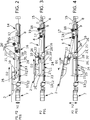
- the figures 1 to 7 show a mechanical device for charging station comprising at least:
- the mechanical device is characterized in that it comprises:
- first actuator 7 only one actuator (first actuator 7) is required to drive the motion of the arm 1 for coupling the charger plug 2 and the charging receiver together.
- first actuator 7) only one actuator (first actuator 7) needs to be controlled.
- the mechanical device according to the invention is provided to permit the translation of the arm 1, along the first direction D1 and the second direction D2, which are opposite, when the arm 1 is at the horizontal (initial angle) as well as when the arm 1 is tilted (final angle).
- the mechanical device according to the invention is also provided to permit the rotation of the arm 1,
- the mechanical device according to the invention is suitable to be located underneath an electric vehicle.
- the charger plug 2 when the charger plug 2 is connected to the mechanical device according to the invention, the charger plug 2 can be moved in the direction of the bottom (not shown) of the electric vehicle on which the charging receiver (not shown) of the electric vehicle is located (upward elevation). Then, the charger plug 2 can be moved in translation in the direction of the charging receiver, while being guided by the bottom of the electric vehicle and then in the reverse direction. Then, the charger plug 2 can be moved in the direction of the ground (not shown) (downward elevation).
- the first and second locking elements 10, 11 are provided to prevent said rotation motion of the arm 1, when not required.
- the arm 1 is only moved in said translation motion.
- the first direction D1 and the second direction D2 are horizontal.
- the first actuator 7 consists in an electric motor and the translation means 5 comprises a worm drive 12 having first and second ends 13, 14, the first end 13 being mechanically connected to the electric motor, so that it drives said worm drive 12, and the second end 14 being mechanically connected to support means 15, which are mechanically connected to the second end 4 of the arm 1.
- said worm drive 12 is provided to convert a rotation motion of the electric motor in a translation motion.
- the mechanical device comprises linear guiding means 16 mechanically connected to the second end 4 of the arm 1.
- said linear guiding means 16 are provided to guide said second end 4 of the arm 1 along said translation motion along first and second directions D1, D2.
- said linear guiding means 16 consists in a sliding guide.
- the linear guiding means 16 are affixed to a support, such as the ground.
- the linear guiding means 16 are mechanically connected to the support means 15.
- the at least one cam 9 comprises at least a cam profile 17 and a follower 18, the cam profile 17 being suitable to cooperate with said follower 18, the follower 18 being mechanically connected to the return means 8.
- the mechanical device comprises preferably two cams 9, and each of these cams 9 comprises one cam profile 17 and one follower 18.
- the cam 9 is provided to convert the translation motion of the arm 1 into a rotation motion of the arm 1.
- the return means 8 are provided to create a torque on the first pivot 6 in the elevation direction of the arm 1. The torque, which is applied by the return means 8, are also provided to maintain the contact between the cam profile 17 and the follower 18.
- the return means 8 comprise at least a pneumatic cylinder.
- the support means 15 are mechanically connected to the follower 18 and to the return means 8 for connecting the return means 8 and the cam 9/follower 18 to the second end 4 of the arm 1.
- the follower 18 is mounted on a support plate 19 pivotally mounted on the support means 15 around first pivot 6, the return means 8 being mechanically connected to the support plate 19.
- the follower 18 consists in a roller, as shown in figures 1 to 7 .
- the cam profile 17 consists in an inclined guide rail arranged parallel to said first direction D1 and second direction D2.
- each of the two cams 9 comprises one inclined guide rail.
- the inclined guide rail could be affixed to a support, such as the ground.
- the first locking means 10 comprises at least a pin and the second locking means 11 comprises at least one linear groove 20, 20', the pin being suitable to be connected with the linear groove 20, 20', so that in an inserted position P1 of said first and second locking means 10, 11, the pin is inserted in the groove 20, 20', for moving said arm 1 in said translation motion at said first height h1.
- the pin is inserted into said groove 20, 20', and thus the rotation motion of the arm 1 is prevented during the translation motion along first or second directions D1, D2. Consequently, the first end 3 of the arm 1 is maintained at first height h1.
- the pin of the first locking means 11 is mounted on a pivot 10' to control pitch trim.
- the second locking means 11 comprises at least an insertion hole 21, 21' opening on the at least one linear groove 20, 20' and suitable to insert/remove the pin in/from the at least one linear groove 20, 20'.
- the threshold distance is reached, when the pin is inserted into or faces said insertion hole 21, 21'.
- the second locking means 11 comprises a locking element 22 arranged to permit the removal/insertion of the pin from/in the at least one linear groove 20, 20' through the insertion hole 21, 21', in a unlocked position P2 of the locking element 22, and/or to prevent the removal of the pin from the at least one linear groove 20, 20' through the insertion hole 20, 20', in a locked position P3 of the locking element 22.
- the locking element 22 is arranged to authorize the passage of the pin through the insertion hole 21, 21'.
- the pin cannot be removed from the at least one linear groove 20, 20'.
- the locking element 22 is arranged to authorize the passage of the pin through the insertion hole 20, 20'.
- the locking element 22 is arranged to prevent the passage of the pin through the insertion hole 20, 20'.
- the locking element 22 is arranged to prevent the passage of the pin through the insertion hole 20, 20'.
- the second locking means 11 comprises a first element 23 and second element 24 comprising respectively first and second linear grooves 20, 20' facing at least partially each other, and comprising respectively first and second insertion holes 21, 21', the second linear groove 20' comprising a first end 25 and a second end 26, which respectively form a first stop and a second stop, the first element 23 comprising the locking element 22, the second element 24 being slidably mounted on said first element 23 and being suitable to move by means of the pin of the first locking means 10 inserted into the first and second grooves 20, 20' between a first position P01 and a second position P02, so that in the first position P01 corresponding to the unlocked position P2, the first and second insertion holes 21, 21' face each other and so that in the second position P02 corresponding to the locked position P3, the locking element 22 and the second insertion hole 21' face each other.
- the locking element 22 is in the locked position P3, as illustrated in figure 5 .
- the first and second locking means 10, 11 are in the inserted position P1 and the arm 1 is moved latter in the translation motion along said first direction D1 and the pin reaches the first stop, as the pin is moving pin, it causes the second element 24 to move from the second position P02 to the first position P01.
- the locking element 22 is in the unlocked position P2, as illustrated in figures 2 and 7 .
- the first groove 20 has a first length and the second groove 20' has a second length which is smaller than said first length.
- the second linear groove 20' comprises a first end 25' and a second end 26'.
- the locking element 22 consists in a hook located between said first insertion hole 21 and said second end 26'.
- the second element 24 is slidably mounted on said first element 23 by connection means, such as a guiding groove 27 parallel to the second groove 20' and cooperating with at least two screws 28 connected to the firs element 23 and inserted in said guiding groove 27 ( figures 1 to 7 ).
- connection means such as a guiding groove 27 parallel to the second groove 20' and cooperating with at least two screws 28 connected to the firs element 23 and inserted in said guiding groove 27 ( figures 1 to 7 ).
- the first element 23 is a plate having a L section.
- the first element 23 could be fixed to a support such as the ground by fixation means 29.
- the second element 24 is a planar plate.
- the arm 1 comprises two bars 1' forming a parallelogram which are linked at each end by connection supports comprising pivots.
- This configuration of the arm 1 is provided to correct lateral positioning error.
- the charger plug 2 for supplying electric energy to an electric vehicle 3 comprises at least a first electric connector 30 comprising at least one first electric contact (not shown), a support 31 comprising a bottom face (not shown) on which the first electric connector 30 is mounted and an upper face 31a arranged to slide on the bottom of the electric vehicle, the first electric connector 30 being arranged to be coupled with a corresponding second electric connector (not shown) of a charging receiver (not shown) located on the bottom of the electric vehicle so that the at least one first electric contact being electrically connected with at least one second electric contact (not shown) of the second electric connector.
- the support 30 comprises guiding means 32, 33 comprising a reception area 34 arranged to surround at least partially the charging receiver and arranged to align the first electric connector 30 and the second electric connector, when moving the charger plug 2 in the direction of the charging receiver or conversely.
- the guiding means 32, 33 are provided to mechanically align the first electric connector 30 with the second electric connector of the charging receiver, so that they can connect properly to charge the battery of the electric vehicle with electric energy. These mechanical guiding means 32, 33 advantageously are not likely to be damaged because of extreme temperatures, rain, snow, ice, external corrosion and/or dust.
- the upper face 31a can slide on the bottom of the electric vehicle 3 in the direction of the charging receiver, until the guiding means 32, 33 lean against the charging receiver and that the reception area 34 and a portion of complementary shape of the charging receiver connect together.
- the bottom of the electric vehicle can slide on the upper face 31a, until the guiding means 32, 33 lean against the charging receiver and that the reception area 34 and a portion of complementary shape of the charging receiver connect together.
- the guiding means comprises a first member 32 projecting from the support 31 on a first lateral side of the first electric connector 30 and a second member 33 projecting from the support 31 on a second lateral side of the first electric connector 30 respectively delimiting a first portion and a second portion of the reception area 34, the first member 32 and the second member 33 being positioned at a predetermined distance from one to another and being separated from one to another by a base portion of the reception area 34.
- the reception area 34 has a U-shaped delimited by the first portion, the second portion and the base portion.
- the charger plug 2 comprises means 35 for opening a protection lid (not shown) of the charging receiver arranged to cooperate with corresponding means for opening the protection lid of the charging receiver.
- These means for opening 35 the protection lid of the charging receiver are provided to automatically open the protection lid, after the connection between the portion of the protection lid and the reception area 34, so that the protection lid uncovers the second electric connector to enable the electric connection between the second electric contact and the first electric contact.
- the protection lid enables protecting the second electric connector from the outdoor conditions as long as it is not connected to first electric connector 34, without disturbing a subsequent connection with the first electric connector 34, thanks to the means for opening the protection lid.
- the means for opening the protection lid comprise a first inclined guide rail 35 projecting from the bottom face of the support 31 and surrounding the first lateral side of the first electric connector 30, and a second inclined guide rail 35 projecting from the bottom face of the support 31 and surrounding the second lateral side of the first electric connector 34, the first inclined guide rail 35 and the second inclined guide rail 35 being arranged to cooperate respectively with the corresponding means for opening the protection lid of the charging receiver consisting of a first protrusion (not shown) projecting from a first lateral wall (not shown) of the protection lid of the charging receiver and a second protrusion (not shown) projecting from a second lateral wall of the protection lid.
- first inclined guide rail 35 and second inclined guide rail 35 respectively are provided to lean against the first protrusion and second protrusion, when the charger plug 2 and the charging receiver are moved relative to each other, in order to rotate the protection lid from a first position (not shown) to a second position (not shown), in the clockwise direction and then uncover the second electric connector.
- the first inclined guide rail 35 protrudes perpendicularly to the bottom face of the support 31 along the first portion of the reception area 34 and the second inclined guide rail 35 protrudes perpendicularly to the bottom face of the support 31 along the second portion of the reception area 34.
- the support 31 has a planar shape comprising the bottom face on which the first electric connector 30 is mounted and the upper face 31a arranged to slide on the bottom of the electric vehicle.
- This planar shape is provided to ease the sliding of the support 31 with respect to the bottom of the electric vehicle 3.
- the upper face 31a of the support 31 comprises a plurality of grooves 36, each groove 36 extending on a longitudinal direction of the support 31 and leading to the reception area 34 by an open end 37, each groove 36 being arranged to receive a corresponding pin (not shown) protruding from the bottom of the electric vehicle.
- This plurality of grooves 36 is provided to improve the guiding of the support 31 with respect to the bottom of the electric vehicle.
- the open end 37 has a funnel shape.
- This funnel shape is provided to ease the insertion of the pins in the grooves 36.
- the charger plug 2 comprises at least one positioning pin 38.
- the first electric connector 30 is a standard connector according to the standard IEC 62196-1/-2/-3.
- the present invention also relates to a protection enclosure 39 for protecting said mechanical device according to the present invention.
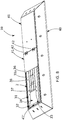
- the protection enclosure 39 encloses the mechanical device in a closed position ( figure 8 ) and encloses only partially the mechanical device in an open position (not shown). Indeed, in the open position, the arm 1 projects outside the protection enclosure 39.
- the protection enclosure 39 is in the closed position ( figure 8 ).
- the protection enclosure is in the open position (not shown).
- said charger plug 2 when the arm 1 is connected to the charger plug 2, said charger plug 2 is also enclosed in the protection enclosure 39, at least partially, in the closed position ( figure 8 ) and projects outside, in the open position (not shown).
- the protection enclosure 39 is suitable to be located on the ground and/or under the ground.
- the protection enclosures 39 comprises a base 40 having a reception area where the mechanical device according to the present invention is enclosed in said closed position, and cover means 41, 41', which covers the mechanical device.
- said closed protection the arm 1 is enclosed in the reception area and said cover means 41, 41' close, at least partially, the reception area and, in the open position, the arm 1 projects outside the reception area and said cover means 41, 41' does not totally close the reception area.
- said charger plug 2 when the arm 1 is connected to the charger plug 2, said charger plug 2 is also enclosed in the reception area and closes the reception area, in the closed position ( figure 8 ), and projects outside the reception area, in the open position.
- the cover means 41 comprises two plates, which are linked together by at least one pivot 42, and which cover the arm 1.
- the cover means 41' comprises another plate which covers the first actuator 7.
- the invention also relates to a charging station comprising said mechanical device according to the present invention and/or said protection enclosure 39 according to the present invention.
- the invention allows implementing a method according to the invention comprising the steps which are described below.
- the arm 1 is horizontal and is tilted at said initial angle, which is approximately equal to zero and the first end 3 is at first height h1. Then, the arm 1 is moved in said translation motion along said second direction D2 by means of said translation means 5, which are actuate by the first actuator 7 ( figures 2 and 3 ).
- the translation direction changes from the second direction D2 to the first direction D1.
- the arm 1 is moved in said further rotation motion during said translation motion along said first direction D1.
- the arm 1 is tilted from the initial angle to the final angle by means of the return means 8 and the cam 9. Consequently, the charger plug 2 can be moved in the direction of the bottom of the electric vehicle on which the charging receiver of the electric vehicle is located.
- the arm 1, which is tilted at said final angle firstly is moved in said translation motion along said first direction D1.
- the arm 1 is moved in said translation motion along said second direction D2 (not shown). Consequently, the charger plug 2 can be moved in the direction of the charging receiver while being guided by the bottom of the electric vehicle.
- the arm 1 is moved in said further rotation motion during said translation motion along said second direction D2 ( figure 4 ).
- the arm 1 is tilted from the final angle to the initial angle by means of the return means 8 and the cam 9.
- the translation direction changes from the second direction D2 to the first direction D1.
- the arm 1 is horizontal and is tilted at said initial angle, which is approximately equal to zero and the first end 3 is at first height h1. Then, the arm 1 is moved in said translation motion along said first direction D1 by means of said translation means 5, which are actuate by the first actuator 7 ( figures 5, 6 and 7 ).
- the first and second locking means 10, 11 are connected together to prevent rotation, when moving the arm 1 in translation motion along second direction D2.
- the first and second locking means 10, 11 could be disconnected to permit rotation, when moving the arm 1 in translation motion along first direction D1. As shown in figure 4 , the first and second locking means 10, 11 are disconnected to permit rotation motion.
- the first and second locking means 10, 11 are connected together to prevent rotation, when moving the arm 1 in translation motion along the first direction D1.
- the locking element 12 is in the unlocked position P2.
- the locking element is moved from the unlocked position P2 to the locked position P3 ( figure 5 ).
- the pin reaches the second stop and moves the second element 24.
- the translation direction changes from the second direction D2 to the first direction D1.
- the locking element is moved from the locked position P3 to the unlocked position P2 ( figure 5 ). Indeed, during said translation motion along said first direction D1, the pin reaches the first stop and moves the second element 24. direction D1.
- the protection enclosure 39 moves from the closed position to the open position.
- the protection enclosure 39 is in the open position.
- the protection enclosure 39 moves from the open position to the closed position.
Landscapes
- Engineering & Computer Science (AREA)
- Power Engineering (AREA)
- Transportation (AREA)
- Mechanical Engineering (AREA)
- Electric Propulsion And Braking For Vehicles (AREA)
- Charge And Discharge Circuits For Batteries Or The Like (AREA)
Priority Applications (4)
| Application Number | Priority Date | Filing Date | Title |
|---|---|---|---|
| ES18305429T ES2906150T3 (es) | 2018-04-10 | 2018-04-10 | Dispositivo mecánico para estación de carga |
| EP18305429.5A EP3552863B1 (de) | 2018-04-10 | 2018-04-10 | Mechanische vorrichtung für eine ladestation |
| CN201920476225.2U CN211684687U (zh) | 2018-04-10 | 2019-04-09 | 用于充电站的机械设备 |
| AU2019202482A AU2019202482A1 (en) | 2018-04-10 | 2019-04-09 | Mechanical device for charging station |
Applications Claiming Priority (1)
| Application Number | Priority Date | Filing Date | Title |
|---|---|---|---|
| EP18305429.5A EP3552863B1 (de) | 2018-04-10 | 2018-04-10 | Mechanische vorrichtung für eine ladestation |
Publications (2)
| Publication Number | Publication Date |
|---|---|
| EP3552863A1 true EP3552863A1 (de) | 2019-10-16 |
| EP3552863B1 EP3552863B1 (de) | 2021-11-24 |
Family
ID=62002605
Family Applications (1)
| Application Number | Title | Priority Date | Filing Date |
|---|---|---|---|
| EP18305429.5A Active EP3552863B1 (de) | 2018-04-10 | 2018-04-10 | Mechanische vorrichtung für eine ladestation |
Country Status (4)
| Country | Link |
|---|---|
| EP (1) | EP3552863B1 (de) |
| CN (1) | CN211684687U (de) |
| AU (1) | AU2019202482A1 (de) |
| ES (1) | ES2906150T3 (de) |
Cited By (2)
| Publication number | Priority date | Publication date | Assignee | Title |
|---|---|---|---|---|
| EP3835113A1 (de) | 2019-12-10 | 2021-06-16 | Hager-Electro Sas | Verbindungsanordnung zur versorgung eines fahrzeuges mit elektrischer energie von einer bodenladestation |
| US11718194B2 (en) | 2018-11-06 | 2023-08-08 | Jaro Fleet Technologies, Inc. | Charging system for electric vehicles |
Families Citing this family (1)
| Publication number | Priority date | Publication date | Assignee | Title |
|---|---|---|---|---|
| CN114801822B (zh) * | 2022-03-23 | 2024-09-20 | 湖南大学 | 一种基于电磁感应原理的多角度无线充电板 |
Citations (5)
| Publication number | Priority date | Publication date | Assignee | Title |
|---|---|---|---|---|
| DE4236286A1 (de) * | 1992-10-28 | 1994-05-05 | Daimler Benz Ag | Verfahren und Anordnung zum automatischen berührungslosen Laden |
| US5821731A (en) * | 1996-01-30 | 1998-10-13 | Sumitomo Wiring Systems, Ltd. | Connection system and connection method for an electric automotive vehicle |
| DE102009001080A1 (de) * | 2009-02-23 | 2010-08-26 | Robert Bosch Gmbh | Autonome Ladevorrichtung für Plugln-Hybrid-Fahrzeuge |
| US20130249470A1 (en) * | 2012-03-21 | 2013-09-26 | Ford Global Technologies, Llc. | Automotive vehicle charge system |
| US20170096073A1 (en) | 2014-04-29 | 2017-04-06 | Tesla Motors, Inc. | Charging station providing thermal conditioning of electric vehicle during charging session |
-
2018
- 2018-04-10 ES ES18305429T patent/ES2906150T3/es active Active
- 2018-04-10 EP EP18305429.5A patent/EP3552863B1/de active Active
-
2019
- 2019-04-09 CN CN201920476225.2U patent/CN211684687U/zh not_active Expired - Fee Related
- 2019-04-09 AU AU2019202482A patent/AU2019202482A1/en not_active Abandoned
Patent Citations (5)
| Publication number | Priority date | Publication date | Assignee | Title |
|---|---|---|---|---|
| DE4236286A1 (de) * | 1992-10-28 | 1994-05-05 | Daimler Benz Ag | Verfahren und Anordnung zum automatischen berührungslosen Laden |
| US5821731A (en) * | 1996-01-30 | 1998-10-13 | Sumitomo Wiring Systems, Ltd. | Connection system and connection method for an electric automotive vehicle |
| DE102009001080A1 (de) * | 2009-02-23 | 2010-08-26 | Robert Bosch Gmbh | Autonome Ladevorrichtung für Plugln-Hybrid-Fahrzeuge |
| US20130249470A1 (en) * | 2012-03-21 | 2013-09-26 | Ford Global Technologies, Llc. | Automotive vehicle charge system |
| US20170096073A1 (en) | 2014-04-29 | 2017-04-06 | Tesla Motors, Inc. | Charging station providing thermal conditioning of electric vehicle during charging session |
Cited By (2)
| Publication number | Priority date | Publication date | Assignee | Title |
|---|---|---|---|---|
| US11718194B2 (en) | 2018-11-06 | 2023-08-08 | Jaro Fleet Technologies, Inc. | Charging system for electric vehicles |
| EP3835113A1 (de) | 2019-12-10 | 2021-06-16 | Hager-Electro Sas | Verbindungsanordnung zur versorgung eines fahrzeuges mit elektrischer energie von einer bodenladestation |
Also Published As
| Publication number | Publication date |
|---|---|
| EP3552863B1 (de) | 2021-11-24 |
| AU2019202482A1 (en) | 2019-10-24 |
| CN211684687U (zh) | 2020-10-16 |
| ES2906150T3 (es) | 2022-04-13 |
Similar Documents
| Publication | Publication Date | Title |
|---|---|---|
| EP3552863B1 (de) | Mechanische vorrichtung für eine ladestation | |
| EP3552862B1 (de) | Ladestecker zur versorgung eines elektrofahrzeugs mit elektrischer energie, ladestation mit dem ladestecker, ladeempfänger für ein elektrofahrzeug und verfahren zum verbinden des ladeempfängers und des ladesteckers | |
| US10017062B2 (en) | Electric charging device, electric connection device, system and method for charging a battery of a vehicle | |
| US6682353B2 (en) | Connection assembly for connecting an electric system of a vehicle to electric components of a sliding door of the vehicle | |
| US8720059B2 (en) | Apparatus and method for aircraft engine core exchange | |
| US8247921B2 (en) | Power supply apparatus for sliding door | |
| US20250319781A1 (en) | Charging Port Device | |
| US20240337144A1 (en) | Actuation device for charging port socket cap or cover | |
| US20220224048A1 (en) | Automatic coupler assembly | |
| CN112937347A (zh) | 用于从地面充电站向车辆供应电能的连接组件 | |
| EP3249756A1 (de) | Elektrische verbinderanordnung mit einer abdeckungsverriegelungsvorrichtung | |
| JP7055069B2 (ja) | 蓋の取付方法 | |
| US20240383359A1 (en) | Mobile charging device and mobile charging method | |
| KR102662993B1 (ko) | 보호판을 구비한 커넥터 어셈블리 | |
| CN109638503A (zh) | 一种防水防尘电连接器及充电弓充电连接结构 | |
| CN215284332U (zh) | 电池包锁止机构、托架总成及电动汽车 | |
| US11648829B2 (en) | Assembly and method for moving a cover | |
| US20240418017A1 (en) | Operation Assembly for Vehicle Closure Component | |
| US20030141173A1 (en) | Locking device | |
| CN214492508U (zh) | 一种电动车辆及其电池箱系统 | |
| US12062991B2 (en) | Power conversion device | |
| CN117881559A (zh) | 用于车辆车顶的装置和车辆车顶 | |
| DE102024201257A1 (de) | Verfahren zur Montage einer Türkomponente in einer Fahrzeugtür | |
| US20250145268A1 (en) | Connection system for an outboard motor | |
| KR102873139B1 (ko) | 지붕충전 교통수단의 쐐기형 충전장치 |
Legal Events
| Date | Code | Title | Description |
|---|---|---|---|
| PUAI | Public reference made under article 153(3) epc to a published international application that has entered the european phase |
Free format text: ORIGINAL CODE: 0009012 |
|
| STAA | Information on the status of an ep patent application or granted ep patent |
Free format text: STATUS: THE APPLICATION HAS BEEN PUBLISHED |
|
| AK | Designated contracting states |
Kind code of ref document: A1 Designated state(s): AL AT BE BG CH CY CZ DE DK EE ES FI FR GB GR HR HU IE IS IT LI LT LU LV MC MK MT NL NO PL PT RO RS SE SI SK SM TR |
|
| AX | Request for extension of the european patent |
Extension state: BA ME |
|
| STAA | Information on the status of an ep patent application or granted ep patent |
Free format text: STATUS: REQUEST FOR EXAMINATION WAS MADE |
|
| 17P | Request for examination filed |
Effective date: 20200416 |
|
| RBV | Designated contracting states (corrected) |
Designated state(s): AL AT BE BG CH CY CZ DE DK EE ES FI FR GB GR HR HU IE IS IT LI LT LU LV MC MK MT NL NO PL PT RO RS SE SI SK SM TR |
|
| REG | Reference to a national code |
Ref country code: DE Ref legal event code: R079 Ref document number: 602018027095 Country of ref document: DE Free format text: PREVIOUS MAIN CLASS: B60L0011180000 Ipc: B60L0053350000 |
|
| RIC1 | Information provided on ipc code assigned before grant |
Ipc: B60L 53/35 20190101AFI20210622BHEP |
|
| GRAP | Despatch of communication of intention to grant a patent |
Free format text: ORIGINAL CODE: EPIDOSNIGR1 |
|
| STAA | Information on the status of an ep patent application or granted ep patent |
Free format text: STATUS: GRANT OF PATENT IS INTENDED |
|
| INTG | Intention to grant announced |
Effective date: 20210908 |
|
| GRAS | Grant fee paid |
Free format text: ORIGINAL CODE: EPIDOSNIGR3 |
|
| GRAA | (expected) grant |
Free format text: ORIGINAL CODE: 0009210 |
|
| STAA | Information on the status of an ep patent application or granted ep patent |
Free format text: STATUS: THE PATENT HAS BEEN GRANTED |
|
| AK | Designated contracting states |
Kind code of ref document: B1 Designated state(s): AL AT BE BG CH CY CZ DE DK EE ES FI FR GB GR HR HU IE IS IT LI LT LU LV MC MK MT NL NO PL PT RO RS SE SI SK SM TR |
|
| REG | Reference to a national code |
Ref country code: GB Ref legal event code: FG4D |
|
| REG | Reference to a national code |
Ref country code: AT Ref legal event code: REF Ref document number: 1449626 Country of ref document: AT Kind code of ref document: T Effective date: 20211215 |
|
| REG | Reference to a national code |
Ref country code: DE Ref legal event code: R096 Ref document number: 602018027095 Country of ref document: DE |
|
| REG | Reference to a national code |
Ref country code: IE Ref legal event code: FG4D |
|
| REG | Reference to a national code |
Ref country code: NL Ref legal event code: FP |
|
| REG | Reference to a national code |
Ref country code: LT Ref legal event code: MG9D |
|
| REG | Reference to a national code |
Ref country code: ES Ref legal event code: FG2A Ref document number: 2906150 Country of ref document: ES Kind code of ref document: T3 Effective date: 20220413 |
|
| PG25 | Lapsed in a contracting state [announced via postgrant information from national office to epo] |
Ref country code: RS Free format text: LAPSE BECAUSE OF FAILURE TO SUBMIT A TRANSLATION OF THE DESCRIPTION OR TO PAY THE FEE WITHIN THE PRESCRIBED TIME-LIMIT Effective date: 20211124 Ref country code: LT Free format text: LAPSE BECAUSE OF FAILURE TO SUBMIT A TRANSLATION OF THE DESCRIPTION OR TO PAY THE FEE WITHIN THE PRESCRIBED TIME-LIMIT Effective date: 20211124 Ref country code: FI Free format text: LAPSE BECAUSE OF FAILURE TO SUBMIT A TRANSLATION OF THE DESCRIPTION OR TO PAY THE FEE WITHIN THE PRESCRIBED TIME-LIMIT Effective date: 20211124 Ref country code: BG Free format text: LAPSE BECAUSE OF FAILURE TO SUBMIT A TRANSLATION OF THE DESCRIPTION OR TO PAY THE FEE WITHIN THE PRESCRIBED TIME-LIMIT Effective date: 20220224 |
|
| PG25 | Lapsed in a contracting state [announced via postgrant information from national office to epo] |
Ref country code: IS Free format text: LAPSE BECAUSE OF FAILURE TO SUBMIT A TRANSLATION OF THE DESCRIPTION OR TO PAY THE FEE WITHIN THE PRESCRIBED TIME-LIMIT Effective date: 20220324 Ref country code: SE Free format text: LAPSE BECAUSE OF FAILURE TO SUBMIT A TRANSLATION OF THE DESCRIPTION OR TO PAY THE FEE WITHIN THE PRESCRIBED TIME-LIMIT Effective date: 20211124 Ref country code: PT Free format text: LAPSE BECAUSE OF FAILURE TO SUBMIT A TRANSLATION OF THE DESCRIPTION OR TO PAY THE FEE WITHIN THE PRESCRIBED TIME-LIMIT Effective date: 20220324 Ref country code: PL Free format text: LAPSE BECAUSE OF FAILURE TO SUBMIT A TRANSLATION OF THE DESCRIPTION OR TO PAY THE FEE WITHIN THE PRESCRIBED TIME-LIMIT Effective date: 20211124 Ref country code: NO Free format text: LAPSE BECAUSE OF FAILURE TO SUBMIT A TRANSLATION OF THE DESCRIPTION OR TO PAY THE FEE WITHIN THE PRESCRIBED TIME-LIMIT Effective date: 20220224 Ref country code: LV Free format text: LAPSE BECAUSE OF FAILURE TO SUBMIT A TRANSLATION OF THE DESCRIPTION OR TO PAY THE FEE WITHIN THE PRESCRIBED TIME-LIMIT Effective date: 20211124 Ref country code: HR Free format text: LAPSE BECAUSE OF FAILURE TO SUBMIT A TRANSLATION OF THE DESCRIPTION OR TO PAY THE FEE WITHIN THE PRESCRIBED TIME-LIMIT Effective date: 20211124 Ref country code: GR Free format text: LAPSE BECAUSE OF FAILURE TO SUBMIT A TRANSLATION OF THE DESCRIPTION OR TO PAY THE FEE WITHIN THE PRESCRIBED TIME-LIMIT Effective date: 20220225 |
|
| PG25 | Lapsed in a contracting state [announced via postgrant information from national office to epo] |
Ref country code: SM Free format text: LAPSE BECAUSE OF FAILURE TO SUBMIT A TRANSLATION OF THE DESCRIPTION OR TO PAY THE FEE WITHIN THE PRESCRIBED TIME-LIMIT Effective date: 20211124 Ref country code: SK Free format text: LAPSE BECAUSE OF FAILURE TO SUBMIT A TRANSLATION OF THE DESCRIPTION OR TO PAY THE FEE WITHIN THE PRESCRIBED TIME-LIMIT Effective date: 20211124 Ref country code: RO Free format text: LAPSE BECAUSE OF FAILURE TO SUBMIT A TRANSLATION OF THE DESCRIPTION OR TO PAY THE FEE WITHIN THE PRESCRIBED TIME-LIMIT Effective date: 20211124 Ref country code: EE Free format text: LAPSE BECAUSE OF FAILURE TO SUBMIT A TRANSLATION OF THE DESCRIPTION OR TO PAY THE FEE WITHIN THE PRESCRIBED TIME-LIMIT Effective date: 20211124 Ref country code: DK Free format text: LAPSE BECAUSE OF FAILURE TO SUBMIT A TRANSLATION OF THE DESCRIPTION OR TO PAY THE FEE WITHIN THE PRESCRIBED TIME-LIMIT Effective date: 20211124 Ref country code: CZ Free format text: LAPSE BECAUSE OF FAILURE TO SUBMIT A TRANSLATION OF THE DESCRIPTION OR TO PAY THE FEE WITHIN THE PRESCRIBED TIME-LIMIT Effective date: 20211124 |
|
| REG | Reference to a national code |
Ref country code: DE Ref legal event code: R097 Ref document number: 602018027095 Country of ref document: DE |
|
| PLBE | No opposition filed within time limit |
Free format text: ORIGINAL CODE: 0009261 |
|
| STAA | Information on the status of an ep patent application or granted ep patent |
Free format text: STATUS: NO OPPOSITION FILED WITHIN TIME LIMIT |
|
| PG25 | Lapsed in a contracting state [announced via postgrant information from national office to epo] |
Ref country code: AL Free format text: LAPSE BECAUSE OF FAILURE TO SUBMIT A TRANSLATION OF THE DESCRIPTION OR TO PAY THE FEE WITHIN THE PRESCRIBED TIME-LIMIT Effective date: 20211124 |
|
| 26N | No opposition filed |
Effective date: 20220825 |
|
| PG25 | Lapsed in a contracting state [announced via postgrant information from national office to epo] |
Ref country code: SI Free format text: LAPSE BECAUSE OF FAILURE TO SUBMIT A TRANSLATION OF THE DESCRIPTION OR TO PAY THE FEE WITHIN THE PRESCRIBED TIME-LIMIT Effective date: 20211124 |
|
| REG | Reference to a national code |
Ref country code: CH Ref legal event code: PL |
|
| REG | Reference to a national code |
Ref country code: BE Ref legal event code: MM Effective date: 20220430 |
|
| PG25 | Lapsed in a contracting state [announced via postgrant information from national office to epo] |
Ref country code: MC Free format text: LAPSE BECAUSE OF FAILURE TO SUBMIT A TRANSLATION OF THE DESCRIPTION OR TO PAY THE FEE WITHIN THE PRESCRIBED TIME-LIMIT Effective date: 20211124 Ref country code: LU Free format text: LAPSE BECAUSE OF NON-PAYMENT OF DUE FEES Effective date: 20220410 Ref country code: LI Free format text: LAPSE BECAUSE OF NON-PAYMENT OF DUE FEES Effective date: 20220430 Ref country code: CH Free format text: LAPSE BECAUSE OF NON-PAYMENT OF DUE FEES Effective date: 20220430 |
|
| PG25 | Lapsed in a contracting state [announced via postgrant information from national office to epo] |
Ref country code: BE Free format text: LAPSE BECAUSE OF NON-PAYMENT OF DUE FEES Effective date: 20220430 |
|
| REG | Reference to a national code |
Ref country code: AT Ref legal event code: UEP Ref document number: 1449626 Country of ref document: AT Kind code of ref document: T Effective date: 20211124 |
|
| PG25 | Lapsed in a contracting state [announced via postgrant information from national office to epo] |
Ref country code: IE Free format text: LAPSE BECAUSE OF NON-PAYMENT OF DUE FEES Effective date: 20220410 |
|
| P01 | Opt-out of the competence of the unified patent court (upc) registered |
Effective date: 20230606 |
|
| PGFP | Annual fee paid to national office [announced via postgrant information from national office to epo] |
Ref country code: ES Payment date: 20230503 Year of fee payment: 6 |
|
| PGFP | Annual fee paid to national office [announced via postgrant information from national office to epo] |
Ref country code: GB Payment date: 20230427 Year of fee payment: 6 |
|
| PG25 | Lapsed in a contracting state [announced via postgrant information from national office to epo] |
Ref country code: HU Free format text: LAPSE BECAUSE OF FAILURE TO SUBMIT A TRANSLATION OF THE DESCRIPTION OR TO PAY THE FEE WITHIN THE PRESCRIBED TIME-LIMIT; INVALID AB INITIO Effective date: 20180410 |
|
| PG25 | Lapsed in a contracting state [announced via postgrant information from national office to epo] |
Ref country code: MK Free format text: LAPSE BECAUSE OF FAILURE TO SUBMIT A TRANSLATION OF THE DESCRIPTION OR TO PAY THE FEE WITHIN THE PRESCRIBED TIME-LIMIT Effective date: 20211124 Ref country code: CY Free format text: LAPSE BECAUSE OF FAILURE TO SUBMIT A TRANSLATION OF THE DESCRIPTION OR TO PAY THE FEE WITHIN THE PRESCRIBED TIME-LIMIT Effective date: 20211124 |
|
| PG25 | Lapsed in a contracting state [announced via postgrant information from national office to epo] |
Ref country code: TR Free format text: LAPSE BECAUSE OF FAILURE TO SUBMIT A TRANSLATION OF THE DESCRIPTION OR TO PAY THE FEE WITHIN THE PRESCRIBED TIME-LIMIT Effective date: 20211124 |
|
| PG25 | Lapsed in a contracting state [announced via postgrant information from national office to epo] |
Ref country code: MT Free format text: LAPSE BECAUSE OF FAILURE TO SUBMIT A TRANSLATION OF THE DESCRIPTION OR TO PAY THE FEE WITHIN THE PRESCRIBED TIME-LIMIT Effective date: 20211124 |
|
| GBPC | Gb: european patent ceased through non-payment of renewal fee |
Effective date: 20240410 |
|
| PG25 | Lapsed in a contracting state [announced via postgrant information from national office to epo] |
Ref country code: GB Free format text: LAPSE BECAUSE OF NON-PAYMENT OF DUE FEES Effective date: 20240410 |
|
| PG25 | Lapsed in a contracting state [announced via postgrant information from national office to epo] |
Ref country code: GB Free format text: LAPSE BECAUSE OF NON-PAYMENT OF DUE FEES Effective date: 20240410 |
|
| PGFP | Annual fee paid to national office [announced via postgrant information from national office to epo] |
Ref country code: NL Payment date: 20250427 Year of fee payment: 8 |
|
| REG | Reference to a national code |
Ref country code: ES Ref legal event code: FD2A Effective date: 20250527 |
|
| PGFP | Annual fee paid to national office [announced via postgrant information from national office to epo] |
Ref country code: DE Payment date: 20250429 Year of fee payment: 8 |
|
| PG25 | Lapsed in a contracting state [announced via postgrant information from national office to epo] |
Ref country code: ES Free format text: LAPSE BECAUSE OF NON-PAYMENT OF DUE FEES Effective date: 20240411 |
|
| PGFP | Annual fee paid to national office [announced via postgrant information from national office to epo] |
Ref country code: IT Payment date: 20250422 Year of fee payment: 8 |
|
| PGFP | Annual fee paid to national office [announced via postgrant information from national office to epo] |
Ref country code: FR Payment date: 20250425 Year of fee payment: 8 |
|
| PGFP | Annual fee paid to national office [announced via postgrant information from national office to epo] |
Ref country code: AT Payment date: 20250319 Year of fee payment: 8 |