EP3552866A1 - Système de recharge pour véhicule électrique - Google Patents
Système de recharge pour véhicule électrique Download PDFInfo
- Publication number
- EP3552866A1 EP3552866A1 EP19168799.5A EP19168799A EP3552866A1 EP 3552866 A1 EP3552866 A1 EP 3552866A1 EP 19168799 A EP19168799 A EP 19168799A EP 3552866 A1 EP3552866 A1 EP 3552866A1
- Authority
- EP
- European Patent Office
- Prior art keywords
- recharge
- carried
- connection
- vehicle
- recharge system
- Prior art date
- Legal status (The legal status is an assumption and is not a legal conclusion. Google has not performed a legal analysis and makes no representation as to the accuracy of the status listed.)
- Granted
Links
Images

Classifications
-
- B—PERFORMING OPERATIONS; TRANSPORTING
- B60—VEHICLES IN GENERAL
- B60L—PROPULSION OF ELECTRICALLY-PROPELLED VEHICLES; SUPPLYING ELECTRIC POWER FOR AUXILIARY EQUIPMENT OF ELECTRICALLY-PROPELLED VEHICLES; ELECTRODYNAMIC BRAKE SYSTEMS FOR VEHICLES IN GENERAL; MAGNETIC SUSPENSION OR LEVITATION FOR VEHICLES; MONITORING OPERATING VARIABLES OF ELECTRICALLY-PROPELLED VEHICLES; ELECTRIC SAFETY DEVICES FOR ELECTRICALLY-PROPELLED VEHICLES
- B60L53/00—Methods of charging batteries, specially adapted for electric vehicles; Charging stations or on-board charging equipment therefor; Exchange of energy storage elements in electric vehicles
- B60L53/30—Constructional details of charging stations
- B60L53/35—Means for automatic or assisted adjustment of the relative position of charging devices and vehicles
- B60L53/37—Means for automatic or assisted adjustment of the relative position of charging devices and vehicles using optical position determination, e.g. using cameras
-
- B—PERFORMING OPERATIONS; TRANSPORTING
- B60—VEHICLES IN GENERAL
- B60L—PROPULSION OF ELECTRICALLY-PROPELLED VEHICLES; SUPPLYING ELECTRIC POWER FOR AUXILIARY EQUIPMENT OF ELECTRICALLY-PROPELLED VEHICLES; ELECTRODYNAMIC BRAKE SYSTEMS FOR VEHICLES IN GENERAL; MAGNETIC SUSPENSION OR LEVITATION FOR VEHICLES; MONITORING OPERATING VARIABLES OF ELECTRICALLY-PROPELLED VEHICLES; ELECTRIC SAFETY DEVICES FOR ELECTRICALLY-PROPELLED VEHICLES
- B60L53/00—Methods of charging batteries, specially adapted for electric vehicles; Charging stations or on-board charging equipment therefor; Exchange of energy storage elements in electric vehicles
- B60L53/10—Methods of charging batteries, specially adapted for electric vehicles; Charging stations or on-board charging equipment therefor; Exchange of energy storage elements in electric vehicles characterised by the energy transfer between the charging station and the vehicle
- B60L53/14—Conductive energy transfer
- B60L53/16—Connectors, e.g. plugs or sockets, specially adapted for charging electric vehicles
-
- B—PERFORMING OPERATIONS; TRANSPORTING
- B60—VEHICLES IN GENERAL
- B60L—PROPULSION OF ELECTRICALLY-PROPELLED VEHICLES; SUPPLYING ELECTRIC POWER FOR AUXILIARY EQUIPMENT OF ELECTRICALLY-PROPELLED VEHICLES; ELECTRODYNAMIC BRAKE SYSTEMS FOR VEHICLES IN GENERAL; MAGNETIC SUSPENSION OR LEVITATION FOR VEHICLES; MONITORING OPERATING VARIABLES OF ELECTRICALLY-PROPELLED VEHICLES; ELECTRIC SAFETY DEVICES FOR ELECTRICALLY-PROPELLED VEHICLES
- B60L53/00—Methods of charging batteries, specially adapted for electric vehicles; Charging stations or on-board charging equipment therefor; Exchange of energy storage elements in electric vehicles
- B60L53/30—Constructional details of charging stations
- B60L53/35—Means for automatic or assisted adjustment of the relative position of charging devices and vehicles
- B60L53/36—Means for automatic or assisted adjustment of the relative position of charging devices and vehicles by positioning the vehicle
-
- Y—GENERAL TAGGING OF NEW TECHNOLOGICAL DEVELOPMENTS; GENERAL TAGGING OF CROSS-SECTIONAL TECHNOLOGIES SPANNING OVER SEVERAL SECTIONS OF THE IPC; TECHNICAL SUBJECTS COVERED BY FORMER USPC CROSS-REFERENCE ART COLLECTIONS [XRACs] AND DIGESTS
- Y02—TECHNOLOGIES OR APPLICATIONS FOR MITIGATION OR ADAPTATION AGAINST CLIMATE CHANGE
- Y02T—CLIMATE CHANGE MITIGATION TECHNOLOGIES RELATED TO TRANSPORTATION
- Y02T10/00—Road transport of goods or passengers
- Y02T10/60—Other road transportation technologies with climate change mitigation effect
- Y02T10/70—Energy storage systems for electromobility, e.g. batteries
-
- Y—GENERAL TAGGING OF NEW TECHNOLOGICAL DEVELOPMENTS; GENERAL TAGGING OF CROSS-SECTIONAL TECHNOLOGIES SPANNING OVER SEVERAL SECTIONS OF THE IPC; TECHNICAL SUBJECTS COVERED BY FORMER USPC CROSS-REFERENCE ART COLLECTIONS [XRACs] AND DIGESTS
- Y02—TECHNOLOGIES OR APPLICATIONS FOR MITIGATION OR ADAPTATION AGAINST CLIMATE CHANGE
- Y02T—CLIMATE CHANGE MITIGATION TECHNOLOGIES RELATED TO TRANSPORTATION
- Y02T10/00—Road transport of goods or passengers
- Y02T10/60—Other road transportation technologies with climate change mitigation effect
- Y02T10/7072—Electromobility specific charging systems or methods for batteries, ultracapacitors, supercapacitors or double-layer capacitors
-
- Y—GENERAL TAGGING OF NEW TECHNOLOGICAL DEVELOPMENTS; GENERAL TAGGING OF CROSS-SECTIONAL TECHNOLOGIES SPANNING OVER SEVERAL SECTIONS OF THE IPC; TECHNICAL SUBJECTS COVERED BY FORMER USPC CROSS-REFERENCE ART COLLECTIONS [XRACs] AND DIGESTS
- Y02—TECHNOLOGIES OR APPLICATIONS FOR MITIGATION OR ADAPTATION AGAINST CLIMATE CHANGE
- Y02T—CLIMATE CHANGE MITIGATION TECHNOLOGIES RELATED TO TRANSPORTATION
- Y02T90/00—Enabling technologies or technologies with a potential or indirect contribution to GHG emissions mitigation
- Y02T90/10—Technologies relating to charging of electric vehicles
- Y02T90/12—Electric charging stations
-
- Y—GENERAL TAGGING OF NEW TECHNOLOGICAL DEVELOPMENTS; GENERAL TAGGING OF CROSS-SECTIONAL TECHNOLOGIES SPANNING OVER SEVERAL SECTIONS OF THE IPC; TECHNICAL SUBJECTS COVERED BY FORMER USPC CROSS-REFERENCE ART COLLECTIONS [XRACs] AND DIGESTS
- Y02—TECHNOLOGIES OR APPLICATIONS FOR MITIGATION OR ADAPTATION AGAINST CLIMATE CHANGE
- Y02T—CLIMATE CHANGE MITIGATION TECHNOLOGIES RELATED TO TRANSPORTATION
- Y02T90/00—Enabling technologies or technologies with a potential or indirect contribution to GHG emissions mitigation
- Y02T90/10—Technologies relating to charging of electric vehicles
- Y02T90/14—Plug-in electric vehicles
Definitions
- the invention relates to a recharge system for an electric vehicle, more in particular to a recharge system of an electric vehicle for the transportation of people, such as a bus.
- partially or totally electric vehicles which comprise a battery system that periodically needs to be charged.
- This battery system can be charged by means of suitable charging systems, for instance an electric cable provided with a suitable DC charging plug, in the yards of public transportation companies; however, due to the numerous variables playing a role in public transportation, such as traffic or the number passengers, which can suddenly change, there is the need to have charging systems comprising charging stations for the electric battery systems located in different points of the area. In this way, bus drivers can charge, when needed, the battery system in the closest charging stations.
- suitable charging systems for instance an electric cable provided with a suitable DC charging plug
- an electric charging element usually a vertically movable pantograph (on the vehicle side or on the charging infrastructure side), which is designed to be coupled to conductive elements fixed on the roof of the bus so as to allow the latter to be statically charged.
- the electric charging element is connected to a high-voltage energy source, which allows the battery pack to be charged in a few minutes.
- Examples of these charging stations can be Opbrid Busbaar ® or WATT ® system PVI.
- pantograph charging means are more exposed to bad weather and, therefore, can more easily be damaged by elements that can surround the station, such as for example tree branches or simply wind.
- the object of the invention is to fulfil the needs discussed above in an economic and completely automated manner.
- Figures 5 to 7 show a recharge system comprising a recharge station 1 for a bus 2, which is located on one of the edges 3a of a road 3 where the bus 2 drives.
- the bus 2 can be any bus provided with an electric battery system comprising at least one electric battery designed to store electric energy which can be used to enable the total or partial electric drive of the bus 2.
- the road 3 comprises stop means 4 configured to allow the driver of the bus 2 to identify the correct positioning of the latter relative to the recharge station 1 along the road 3.
- the stop means 4 can advantageously be known stripes painted along the road 3.
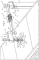
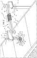
- the recharge station 1 comprises ( figures 1 and 2 ) a support element 5, which is fixed, for example by means of fixing means, such as bolts, or hinged along the edge 3a of the road 3, and a mobile arm 6, which is carried by the support element 5.
- the support element 5 can have any shape, obviously with a greater height than the height of a roof 2r of the bus 2 and defining a longitudinal axis A.
- the support element 5 preferably is a box-like element with the shape of a prism substantially developing along the longitudinal axis A.
- the movable arm 6 preferably comprises an end head 7 and an intermediate element 8 configured to carry the head 7 and connected in a movable manner relative to the support element 5.
- the intermediate element 8 is configured in such a way that an end portion 8a carrying the head 7 has at least two degrees of freedom of movement relative to the support element 5.
- the intermediate element 8 can comprise an element with a longitudinal development, for example a box-like element with shape of a prism, which can be carried in a rotary manner at a further end portion 8b defining a hinge with axis A relative to the support element 5; the intermediate element 8 can further comprise an extendible portion 8c configured to change the longitudinal extension of the intermediate element 8 so that the horizontal distance between the end portion 8a and the end portion 8b can change from a preferable minimum value, equal to at least half the width of the vehicle plus the distance of the vehicle from the hard shoulder, for example 3275 mm, to a maximum value of 4550 mm, more preferably 5550 mm.
- the extendible portion 8c can be obtained in a known manner, for example by means of a hydraulic piston or a mechanical device configured to extend, when operated, and covered by an extendible bellows cover 9 in order to allow the extendible portion to extend from the minimum value to the maximum value of the intermediate element 8.
- the head 7 comprises a main body 7a provided with electric connection means 10 and carried by the intermediate element 8 so that said connection means 10 have two further degrees of freedom of movement relative to it.
- the main body 7a of the head 7 can be carried on the intermediate element 8 in a rotary manner defining a hinge with axis B, parallel to the axis A, relative to the latter and the connection means 10 can slide along an axis C, parallel to the axis B, relative to the main body 7a of the head 7.
- This sliding along the axis C can be carried out by means of a rod 11, which carries, at an end of its, the connection means 10, is inserted, in a mobile manner, in a seat obtained in the main body 7a of the head 7 and is operated in a known manner, for example mechanically or hydraulically.
- the rod 11 can define an upper limit stop, where the connection means define the minimum distance from the main body 7a of the head 7, and a lower limit stop, where the connection means 10 define the maximum distance from the main body 7a of the head 7.
- connection means 10 are configured to allow a high-voltage source (not shown), preferably ranging between 400 and 800 V in direct current, to be connected to the battery system (not shown) of the vehicle 2.
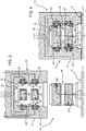
- connection means 10 can comprise a first connection element 15 carried by the head 7 and configured to cooperate with a second connection element 16 carried by the bus 2, preferably on the roof 2r.
- the first connection element 15 comprises a casing 17 with an annular cylindrical shape configured to be fitted around the second connection element 16, which consequently has a substantially cylindrical shape and extends perpendicularly from the roof 2r of the bus 2.
- the second connection element 16 can comprise two poles 20', 20", a positive pole and a negative pole, respectively, possibly configured as rings spaced apart from one another by an electrically insulating material and electrically connected to the battery system of the vehicle by means of respective wires 21.
- the first connection element 15 comprises a first and a second contact means 22', 22" for the poles 20' and 20", respectively, which are configured to selectively come into contact with the respective pole 20', 20" when they are operated.
- the contact means 22', 22" are electrically connected to the high-pressure source by means of respective wires 23 extending inside the head 7, the intermediate element 8 and the support element 5. When they come into contact with the respective pole 20', 20", the contact means 22', 22" allow the high-voltage source to be connected to the battery system of the vehicle 2.
- the contact means 22', 22" can be manufactured as a pair of semicircular walls 24', 24" which are movable relative to the casing 17 between a first non-contact position relative to the second connection element 16 and a second contact position in contact with the poles 20', 20" of the second connection element 16.
- the walls 24', 24" are preferably connected in a movable manner to the inner wall of the casing 17 by means of elastic means, for example helical pins, which are configured to define a pre-set contact load when the second connection element 16 is inserted inside the casing 17.
- the movable parts can be moved by means of linear electromechanical actuators with force-current reaction control.
- Electronic control means of the recharge station as described more in detail below, can be configured to control and maintain the force of the contact (acting upon the current control) compensating, when necessary, possible wears and/or thermal expansions arising in case of high current flows.
- connection means 10 can be further provided with cleaning means configured to clean the inside of the casing 17 (when it is not coupled to the second connection element 16) or the connection element 16 itself, when it is coupled.
- Said cleaning means can comprise compressed air blowers 18, which are fluidically connected to a compressed air source carried, for example, by the recharge station 1, for example through an electric compressor.
- connection means 10 can further comprise localisation means 25 configured to enable an automatic recognition of the relative position of the second connection element 16 carried by the bus 2 relative to the recharge station 1.
- the localisation means 25 preferably comprise laser means 26 and RFID means 27 respectively configured to enable the recognition of the environment surrounding the connection means 10, a precise identification, when the vehicle is still, of the position of the second connection element 16 and an unambiguous identification of the bus 2.
- the laser means 26 comprise range finder laser devices configured to capture the distance between their position and a framed objective, for example the roof 2r of the bus 2 or a highlighted area 2u relative to the roof 2r.
- the RFID sensors 27 preferably comprise RF antennas and a tag reader, which are configured to capture the position of an RFID tag 28 located close to the second connection element 16.
- the recharge station 1 further comprises sensor means (not shown), which are configured to detect impact and/or fire situations.
- the sensor means can comprise acceleration sensors configured to capture sudden changes in the acceleration of the components of the mobile arm 6 and fire sensors located close to the contact means 22', 22" and configured to capture possible fires caused by a short-circuit between the contact means 22', 22" and the poles 20', 20".
- the recharge station 1 further comprises electronic means 30, for example a known electronic control unit, comprising communication means 31, for example through wireless signals, configured to exchange signals with the bus 2, with the localisation means 25 and with the above-mentioned sensor means.
- the electronic means 30 further comprise processing means configured to store and process the aforementioned signals so as to control actuators configured to operate the movements of the mobile arm 6.
- said actuators operate the movements along and/or around the axes A, B, E, and the extension of the portion 8c, so that the connection means 10 are correctly placed above the second connection element 16.
- the electronic means 30 are further configured to control the transfer of electric energy from the high-voltage source to the battery system of the vehicle 2 according to the method described more in detail below.
- the electronic means 30 can be connected, through the communication means 31 or, for example, via cable to a remote control station configured to receive signals from a plurality of control stations 1 connected to one another and to send control instructions to the electronic means 30.
- a bus 2 approaches a recharge station 1. While it approaches the station, the signals sent by the bus 2 are received by the telecommunication means 31 of the electronic means 30 of the recharge station 1, which activates a first step of preliminary controls, as described more in detail below.
- the electronic means 30 controls the actuators in such a way that the mobile arm 6 is positioned so that the head 7 is located with the connection means 10 above the second connection element 16.
- the connection means 10 are coupled to the connection element 16 so that the pairs of walls 24', 24" are in contact, with a correct pre-load, with the respective poles 20', 20".
- connection means 10 are coupled to the connection element 16
- electronic means 30 carry out second functional checks before performing the electric recharge, as described more in detail below.
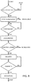
- the recharge station 1 is controlled by the electronic means 30 according to the method described below and schematically shown in figure 8 .
- the bus sends to the electronic means 30 a signal concerning the arrival time and/or the distance from the recharge station 1 and the electronic means 30 evaluate whether said time/distance is greater or smaller than a pre-set time/distance. If so, a step of self-diagnosis the recharge station 1 is activated, otherwise the recharge station 1 waits for a further signal from the bus 2 until the activation of said diagnosis step.
- the diagnosis step involves checking the operation of the actuators of the mobile arm 6, checking the connection to the voltage source and the available power, checking the localisation means 25 and the other sensor means and the use of the localisation means 25, in particular of the laser means 26, in order to check for the presence of obstacle elements (e.g. branches) in the range of action of the mobile arm 6, or even measuring the electric insulation of the connection means 22', 22".
- obstacle elements e.g. branches
- the bus 2 When the bus 2 is positioned along the road 3 close to the stop means 4, this item of information is sent to the electronic means 30, for example the bus 2 can communicate the fact that it is in "parking" mode or that the parking brake was activated, which is an essential condition to activate the recharge procedure.
- connection element 16 of the bus 2 can start.
- This localisation is carried out by the localisation means 25, which are configured to acquire the position of the mobile arm 6 in the environment and the distance between the head 7 of the latter and the connection element 16.
- These items of information are acquired in real time by the electronic means 30, which are configured to process these items of information so as to control the actuators of the mobile arm 6 in such a way that the electric connection means 10 are mechanically coupled to the connection element 16.
- connection means 10 are coupled to the connection element 16
- the electronic means 30 start an electric contact diagnosis step, during which the electric resistance between the poles and between each pole and the ground is measured by means of the contact means 20', 20". This measure provides an estimation of possible current dispersions and the energization of the contact means 20', 20" is inhibited in case these electric dispersions are detected.
- the electronic means 30 enable the connection between the high-voltage source and the battery system of the vehicle 2 by energizing the contact means 22', 22", which are in contact with the poles 20', 20", which, in turn, are connected to the battery system, which is charged.
- This step of charging the battery system of the vehicle 2 can be interrupted when the driver decides to disconnect the recharge through a suitable signal to be sent to the recharge station 1, when a pre-set percentage, for example a 100% charge, is reached or after a pre-set charging time defined based on the minimum time of stay of the vehicle 22 in charge.
- the battery control unit (BMS) of the vehicle 2 can further transfer, through the communication means 31, to the electronic means 30 of the recharge station 1 a series of parameters useful for the management of the fleet of vehicles using said station 1. The transfer of data is completed before the mobile arm 6 goes back to its initial position, therefore without affecting the total charging times.
- the electronic means 30 control the actuators of the arm 6 so as to uncouple the connection means 10 from the second connection element 16 of the vehicle 2 and go back to an initial rest position.
- a first parallel check involves checking whether the vehicle 2 is about to hit a mobile element.
- the acceleration sensor means of the mobile arm 6 transmit an acceleration signal to the electronic means 30, which evaluate whether it exceeds a pre-set acceleration threshold value and inhibit the connection between the voltage source and the contact means 20', 20" accordingly.
- a second parallel check is a fire check due, for example, to a sudden short circuit in the connection means 10.
- the fire sensors evaluate a possible fire ignition and transmit an acceleration signal to the electronic means 30, which, in turn, evaluate whether to inhibit the connection between the voltage source and the contact means 20', 20" accordingly.
- connection and disconnection step carried out to connect and disconnect the connection means 10 there can be an intermediate cleaning step to clean the first and the second connection element 15, 16.
- the electronic means 30 activate the blowers so as to enable the delivery of compressed air on the poles 20', 20" and the contact means 22', 22".
- the electronic means 30 are further configured to store data concerning the use of the elements of the recharge station, so as to build a history of the uses of each element.
- the recharge station 1 is small-sized and has a small impact from the visual point of view.
- connection means 10 ensure a precise coupling between bus 2 and recharge station 1. Furthermore, the localisation means 25 enable, besides the recognition of elements hindering the movement of the mobile arm 6, the precise recognition of the second connection element 16. In this way, the recharge station 1 can be used for different types of buses having the connection element 16 placed in different points.
- connection elements 15, 16 are mechanically coupled to one another by means of a male-female shape coupling ensures a precise coupling, which is also reliable over time. This precision and reliability is further increased by the use of contact means 22', 22" for the poles 20', 20" with a pre-set load or an active control of the contact force.
- connection elements 15, 16 prevents impurities and/or dirt (for example small branches, waste, dust or any other foreign element) from jeopardizing the electric-mechanical contact between them.
- range-finder laser technology combined with the use of RFID means, allows the connection element 16 to be located in a precise and accurate manner and enables a recognition of the type of vehicle 2 of the vehicle 2 itself.
- fire/acceleration sensors increases the safety of the recharge station during the transfer of energy from the voltage source to the battery system of the vehicle.
- the use of the electronic means 30 allows for an automatic control, for example according to the method described herein, of the recharge station 1. These means can further communicate with the vehicles in circulation, with other recharge stations and store data useful for the maintenance/periodic replacement of elements of the recharge station.
- a network comprising different recharge stations 1 can globally be controlled by means of a remote unit connected to each electronic means 30.
- the shape of the recharge station 1 can be changed, though without going beyond the functions claimed herein.
- the same also applies to the types of handling of the mobile arm 6.
- connection means 10 could have a different shape and the operation of the contact means 22', 22" as well as their number could be different.
Landscapes
- Engineering & Computer Science (AREA)
- Power Engineering (AREA)
- Transportation (AREA)
- Mechanical Engineering (AREA)
- Charge And Discharge Circuits For Batteries Or The Like (AREA)
- Electric Propulsion And Braking For Vehicles (AREA)
Applications Claiming Priority (1)
| Application Number | Priority Date | Filing Date | Title |
|---|---|---|---|
| IT201800004408 | 2018-04-11 |
Publications (2)
| Publication Number | Publication Date |
|---|---|
| EP3552866A1 true EP3552866A1 (fr) | 2019-10-16 |
| EP3552866B1 EP3552866B1 (fr) | 2021-12-01 |
Family
ID=62816941
Family Applications (1)
| Application Number | Title | Priority Date | Filing Date |
|---|---|---|---|
| EP19168799.5A Active EP3552866B1 (fr) | 2018-04-11 | 2019-04-11 | Systeme de recharge pour un vehicule electrique |
Country Status (2)
| Country | Link |
|---|---|
| EP (1) | EP3552866B1 (fr) |
| ES (1) | ES2907038T3 (fr) |
Cited By (3)
| Publication number | Priority date | Publication date | Assignee | Title |
|---|---|---|---|---|
| WO2021260132A1 (fr) * | 2020-06-24 | 2021-12-30 | Webasto SE | Unité de véhicule, unité de mise à la terre et procédé de charge d'une batterie d'un véhicule électrique |
| IT202100022544A1 (it) | 2021-08-30 | 2023-03-02 | Iveco France Sas | Sistema di ricarica di batterie veicolari migliorato e metodo di ricarica relativo |
| US11691529B2 (en) * | 2019-09-23 | 2023-07-04 | Abb Schweiz Ag | Systems and methods for automated electrical connector positioning for electric vehicle charging |
Citations (3)
| Publication number | Priority date | Publication date | Assignee | Title |
|---|---|---|---|---|
| US20130076902A1 (en) * | 2011-09-26 | 2013-03-28 | Universite Laval | Robotically operated vehicle charging station |
| US20170008412A1 (en) * | 2015-07-06 | 2017-01-12 | Hon Hai Precision Industry Co., Ltd. | Battery charging system and apparatus and method for electric vehicle |
| WO2017209735A1 (fr) * | 2016-05-31 | 2017-12-07 | Ford Global Technologies, Llc | Charge mobile pour véhicules électriques |
-
2019
- 2019-04-11 ES ES19168799T patent/ES2907038T3/es active Active
- 2019-04-11 EP EP19168799.5A patent/EP3552866B1/fr active Active
Patent Citations (3)
| Publication number | Priority date | Publication date | Assignee | Title |
|---|---|---|---|---|
| US20130076902A1 (en) * | 2011-09-26 | 2013-03-28 | Universite Laval | Robotically operated vehicle charging station |
| US20170008412A1 (en) * | 2015-07-06 | 2017-01-12 | Hon Hai Precision Industry Co., Ltd. | Battery charging system and apparatus and method for electric vehicle |
| WO2017209735A1 (fr) * | 2016-05-31 | 2017-12-07 | Ford Global Technologies, Llc | Charge mobile pour véhicules électriques |
Cited By (4)
| Publication number | Priority date | Publication date | Assignee | Title |
|---|---|---|---|---|
| US11691529B2 (en) * | 2019-09-23 | 2023-07-04 | Abb Schweiz Ag | Systems and methods for automated electrical connector positioning for electric vehicle charging |
| WO2021260132A1 (fr) * | 2020-06-24 | 2021-12-30 | Webasto SE | Unité de véhicule, unité de mise à la terre et procédé de charge d'une batterie d'un véhicule électrique |
| IT202100022544A1 (it) | 2021-08-30 | 2023-03-02 | Iveco France Sas | Sistema di ricarica di batterie veicolari migliorato e metodo di ricarica relativo |
| WO2023031665A1 (fr) | 2021-08-30 | 2023-03-09 | Iveco France S.A.S. | Système de recharge amélioré pour batteries de véhicule et procédé de recharge associé |
Also Published As
| Publication number | Publication date |
|---|---|
| ES2907038T3 (es) | 2022-04-21 |
| EP3552866B1 (fr) | 2021-12-01 |
Similar Documents
| Publication | Publication Date | Title |
|---|---|---|
| EP3552865A1 (fr) | Procédé de commande pour système de recharge de véhicule électrique | |
| EP3552866B1 (fr) | Systeme de recharge pour un vehicule electrique | |
| US7933687B2 (en) | Moving object capable of recognizing image and moving-object directing system equipped with the same | |
| EP2753490B1 (fr) | Procédé et dispositif de transfert sans fil d'énergie électrique vers des véhicules selon un mode "colonnes de distribution mobiles" | |
| RU2598491C1 (ru) | Система бесконтактной подачи электрической мощности и устройство подачи электрической мощности | |
| CN102738862B (zh) | 移动机器人的自动充电系统 | |
| US5049802A (en) | Charging system for a vehicle | |
| RU2594893C9 (ru) | Система бесконтактной подачи электрической мощности | |
| RU2594175C1 (ru) | Система бесконтактной подачи электрической мощности | |
| CN109878354A (zh) | 一种自动充电装置及其运行方法 | |
| CN110843597B (zh) | 应用于车辆换电的视觉分析系统、方法及换电控制方法 | |
| CN107856572B (zh) | 一种汽车智能无线充电系统及其充电方法 | |
| CN111356605B (zh) | 用于在机动车充电站中运行泊车机器人的方法、系统和计算机程序 | |
| CN105751908A (zh) | 给交通运输工具蓄电池充电的方法 | |
| US20210086601A1 (en) | Linear positioning system for automatic charging device | |
| KR20220000011A (ko) | 전력설비 자율진단 로봇 | |
| WO2020078982A1 (fr) | Appareil de charge mobile pour charger un véhicule électrique, système et procédé de charge pour charger un véhicule électrique | |
| KR101802612B1 (ko) | 이동형 로봇의 모니터링시스템 | |
| US12115867B2 (en) | Method, control circuit and control system for controlling an electrical power collector of a vehicle to collect electrical power from a track line of an electric road system | |
| SE542943C2 (en) | A charging device for a functional module and a vehicle assembled from a set of modules | |
| US20240227589A1 (en) | System and method for a charging assembly | |
| EP2981432B1 (fr) | Dispositif de connexion pour connecter un véhicule à propulsion électrique à une station de charge | |
| TWI717095B (zh) | 自走車及自走車系統 | |
| CN115275703A (zh) | 一种充电接口自动退枪装置、系统及方法 | |
| US20240227599A1 (en) | System and method for a charging assembly |
Legal Events
| Date | Code | Title | Description |
|---|---|---|---|
| PUAI | Public reference made under article 153(3) epc to a published international application that has entered the european phase |
Free format text: ORIGINAL CODE: 0009012 |
|
| STAA | Information on the status of an ep patent application or granted ep patent |
Free format text: STATUS: THE APPLICATION HAS BEEN PUBLISHED |
|
| AK | Designated contracting states |
Kind code of ref document: A1 Designated state(s): AL AT BE BG CH CY CZ DE DK EE ES FI FR GB GR HR HU IE IS IT LI LT LU LV MC MK MT NL NO PL PT RO RS SE SI SK SM TR |
|
| AX | Request for extension of the european patent |
Extension state: BA ME |
|
| STAA | Information on the status of an ep patent application or granted ep patent |
Free format text: STATUS: REQUEST FOR EXAMINATION WAS MADE |
|
| 17P | Request for examination filed |
Effective date: 20200415 |
|
| RBV | Designated contracting states (corrected) |
Designated state(s): AL AT BE BG CH CY CZ DE DK EE ES FI FR GB GR HR HU IE IS IT LI LT LU LV MC MK MT NL NO PL PT RO RS SE SI SK SM TR |
|
| GRAP | Despatch of communication of intention to grant a patent |
Free format text: ORIGINAL CODE: EPIDOSNIGR1 |
|
| STAA | Information on the status of an ep patent application or granted ep patent |
Free format text: STATUS: GRANT OF PATENT IS INTENDED |
|
| RIC1 | Information provided on ipc code assigned before grant |
Ipc: B60L 53/36 20190101AFI20210526BHEP |
|
| INTG | Intention to grant announced |
Effective date: 20210628 |
|
| GRAS | Grant fee paid |
Free format text: ORIGINAL CODE: EPIDOSNIGR3 |
|
| GRAA | (expected) grant |
Free format text: ORIGINAL CODE: 0009210 |
|
| STAA | Information on the status of an ep patent application or granted ep patent |
Free format text: STATUS: THE PATENT HAS BEEN GRANTED |
|
| AK | Designated contracting states |
Kind code of ref document: B1 Designated state(s): AL AT BE BG CH CY CZ DE DK EE ES FI FR GB GR HR HU IE IS IT LI LT LU LV MC MK MT NL NO PL PT RO RS SE SI SK SM TR |
|
| REG | Reference to a national code |
Ref country code: GB Ref legal event code: FG4D |
|
| REG | Reference to a national code |
Ref country code: AT Ref legal event code: REF Ref document number: 1451455 Country of ref document: AT Kind code of ref document: T Effective date: 20211215 Ref country code: CH Ref legal event code: EP |
|
| REG | Reference to a national code |
Ref country code: IE Ref legal event code: FG4D |
|
| REG | Reference to a national code |
Ref country code: DE Ref legal event code: R096 Ref document number: 602019009617 Country of ref document: DE |
|
| REG | Reference to a national code |
Ref country code: DE Ref legal event code: R082 Ref document number: 602019009617 Country of ref document: DE Representative=s name: TER MEER STEINMEISTER & PARTNER PATENTANWAELTE, DE |
|
| REG | Reference to a national code |
Ref country code: LT Ref legal event code: MG9D |
|
| REG | Reference to a national code |
Ref country code: NL Ref legal event code: MP Effective date: 20211201 |
|
| REG | Reference to a national code |
Ref country code: AT Ref legal event code: MK05 Ref document number: 1451455 Country of ref document: AT Kind code of ref document: T Effective date: 20211201 |
|
| REG | Reference to a national code |
Ref country code: ES Ref legal event code: FG2A Ref document number: 2907038 Country of ref document: ES Kind code of ref document: T3 Effective date: 20220421 |
|
| PG25 | Lapsed in a contracting state [announced via postgrant information from national office to epo] |
Ref country code: RS Free format text: LAPSE BECAUSE OF FAILURE TO SUBMIT A TRANSLATION OF THE DESCRIPTION OR TO PAY THE FEE WITHIN THE PRESCRIBED TIME-LIMIT Effective date: 20211201 Ref country code: LT Free format text: LAPSE BECAUSE OF FAILURE TO SUBMIT A TRANSLATION OF THE DESCRIPTION OR TO PAY THE FEE WITHIN THE PRESCRIBED TIME-LIMIT Effective date: 20211201 Ref country code: FI Free format text: LAPSE BECAUSE OF FAILURE TO SUBMIT A TRANSLATION OF THE DESCRIPTION OR TO PAY THE FEE WITHIN THE PRESCRIBED TIME-LIMIT Effective date: 20211201 Ref country code: BG Free format text: LAPSE BECAUSE OF FAILURE TO SUBMIT A TRANSLATION OF THE DESCRIPTION OR TO PAY THE FEE WITHIN THE PRESCRIBED TIME-LIMIT Effective date: 20220301 Ref country code: AT Free format text: LAPSE BECAUSE OF FAILURE TO SUBMIT A TRANSLATION OF THE DESCRIPTION OR TO PAY THE FEE WITHIN THE PRESCRIBED TIME-LIMIT Effective date: 20211201 |
|
| PG25 | Lapsed in a contracting state [announced via postgrant information from national office to epo] |
Ref country code: SE Free format text: LAPSE BECAUSE OF FAILURE TO SUBMIT A TRANSLATION OF THE DESCRIPTION OR TO PAY THE FEE WITHIN THE PRESCRIBED TIME-LIMIT Effective date: 20211201 Ref country code: PL Free format text: LAPSE BECAUSE OF FAILURE TO SUBMIT A TRANSLATION OF THE DESCRIPTION OR TO PAY THE FEE WITHIN THE PRESCRIBED TIME-LIMIT Effective date: 20211201 Ref country code: NO Free format text: LAPSE BECAUSE OF FAILURE TO SUBMIT A TRANSLATION OF THE DESCRIPTION OR TO PAY THE FEE WITHIN THE PRESCRIBED TIME-LIMIT Effective date: 20220301 Ref country code: LV Free format text: LAPSE BECAUSE OF FAILURE TO SUBMIT A TRANSLATION OF THE DESCRIPTION OR TO PAY THE FEE WITHIN THE PRESCRIBED TIME-LIMIT Effective date: 20211201 Ref country code: HR Free format text: LAPSE BECAUSE OF FAILURE TO SUBMIT A TRANSLATION OF THE DESCRIPTION OR TO PAY THE FEE WITHIN THE PRESCRIBED TIME-LIMIT Effective date: 20211201 Ref country code: GR Free format text: LAPSE BECAUSE OF FAILURE TO SUBMIT A TRANSLATION OF THE DESCRIPTION OR TO PAY THE FEE WITHIN THE PRESCRIBED TIME-LIMIT Effective date: 20220302 |
|
| PG25 | Lapsed in a contracting state [announced via postgrant information from national office to epo] |
Ref country code: NL Free format text: LAPSE BECAUSE OF FAILURE TO SUBMIT A TRANSLATION OF THE DESCRIPTION OR TO PAY THE FEE WITHIN THE PRESCRIBED TIME-LIMIT Effective date: 20211201 |
|
| PG25 | Lapsed in a contracting state [announced via postgrant information from national office to epo] |
Ref country code: SM Free format text: LAPSE BECAUSE OF FAILURE TO SUBMIT A TRANSLATION OF THE DESCRIPTION OR TO PAY THE FEE WITHIN THE PRESCRIBED TIME-LIMIT Effective date: 20211201 Ref country code: SK Free format text: LAPSE BECAUSE OF FAILURE TO SUBMIT A TRANSLATION OF THE DESCRIPTION OR TO PAY THE FEE WITHIN THE PRESCRIBED TIME-LIMIT Effective date: 20211201 Ref country code: RO Free format text: LAPSE BECAUSE OF FAILURE TO SUBMIT A TRANSLATION OF THE DESCRIPTION OR TO PAY THE FEE WITHIN THE PRESCRIBED TIME-LIMIT Effective date: 20211201 Ref country code: PT Free format text: LAPSE BECAUSE OF FAILURE TO SUBMIT A TRANSLATION OF THE DESCRIPTION OR TO PAY THE FEE WITHIN THE PRESCRIBED TIME-LIMIT Effective date: 20220401 Ref country code: EE Free format text: LAPSE BECAUSE OF FAILURE TO SUBMIT A TRANSLATION OF THE DESCRIPTION OR TO PAY THE FEE WITHIN THE PRESCRIBED TIME-LIMIT Effective date: 20211201 Ref country code: CZ Free format text: LAPSE BECAUSE OF FAILURE TO SUBMIT A TRANSLATION OF THE DESCRIPTION OR TO PAY THE FEE WITHIN THE PRESCRIBED TIME-LIMIT Effective date: 20211201 |
|
| REG | Reference to a national code |
Ref country code: DE Ref legal event code: R097 Ref document number: 602019009617 Country of ref document: DE |
|
| PG25 | Lapsed in a contracting state [announced via postgrant information from national office to epo] |
Ref country code: IS Free format text: LAPSE BECAUSE OF FAILURE TO SUBMIT A TRANSLATION OF THE DESCRIPTION OR TO PAY THE FEE WITHIN THE PRESCRIBED TIME-LIMIT Effective date: 20220401 |
|
| PLBE | No opposition filed within time limit |
Free format text: ORIGINAL CODE: 0009261 |
|
| STAA | Information on the status of an ep patent application or granted ep patent |
Free format text: STATUS: NO OPPOSITION FILED WITHIN TIME LIMIT |
|
| PG25 | Lapsed in a contracting state [announced via postgrant information from national office to epo] |
Ref country code: DK Free format text: LAPSE BECAUSE OF FAILURE TO SUBMIT A TRANSLATION OF THE DESCRIPTION OR TO PAY THE FEE WITHIN THE PRESCRIBED TIME-LIMIT Effective date: 20211201 Ref country code: AL Free format text: LAPSE BECAUSE OF FAILURE TO SUBMIT A TRANSLATION OF THE DESCRIPTION OR TO PAY THE FEE WITHIN THE PRESCRIBED TIME-LIMIT Effective date: 20211201 |
|
| 26N | No opposition filed |
Effective date: 20220902 |
|
| PG25 | Lapsed in a contracting state [announced via postgrant information from national office to epo] |
Ref country code: SI Free format text: LAPSE BECAUSE OF FAILURE TO SUBMIT A TRANSLATION OF THE DESCRIPTION OR TO PAY THE FEE WITHIN THE PRESCRIBED TIME-LIMIT Effective date: 20211201 |
|
| REG | Reference to a national code |
Ref country code: CH Ref legal event code: PL |
|
| REG | Reference to a national code |
Ref country code: BE Ref legal event code: MM Effective date: 20220430 |
|
| PG25 | Lapsed in a contracting state [announced via postgrant information from national office to epo] |
Ref country code: MC Free format text: LAPSE BECAUSE OF FAILURE TO SUBMIT A TRANSLATION OF THE DESCRIPTION OR TO PAY THE FEE WITHIN THE PRESCRIBED TIME-LIMIT Effective date: 20211201 Ref country code: LU Free format text: LAPSE BECAUSE OF NON-PAYMENT OF DUE FEES Effective date: 20220411 Ref country code: LI Free format text: LAPSE BECAUSE OF NON-PAYMENT OF DUE FEES Effective date: 20220430 Ref country code: CH Free format text: LAPSE BECAUSE OF NON-PAYMENT OF DUE FEES Effective date: 20220430 |
|
| PG25 | Lapsed in a contracting state [announced via postgrant information from national office to epo] |
Ref country code: BE Free format text: LAPSE BECAUSE OF NON-PAYMENT OF DUE FEES Effective date: 20220430 |
|
| PG25 | Lapsed in a contracting state [announced via postgrant information from national office to epo] |
Ref country code: IE Free format text: LAPSE BECAUSE OF NON-PAYMENT OF DUE FEES Effective date: 20220411 |
|
| P01 | Opt-out of the competence of the unified patent court (upc) registered |
Effective date: 20230523 |
|
| PG25 | Lapsed in a contracting state [announced via postgrant information from national office to epo] |
Ref country code: HU Free format text: LAPSE BECAUSE OF FAILURE TO SUBMIT A TRANSLATION OF THE DESCRIPTION OR TO PAY THE FEE WITHIN THE PRESCRIBED TIME-LIMIT; INVALID AB INITIO Effective date: 20190411 |
|
| PG25 | Lapsed in a contracting state [announced via postgrant information from national office to epo] |
Ref country code: MK Free format text: LAPSE BECAUSE OF FAILURE TO SUBMIT A TRANSLATION OF THE DESCRIPTION OR TO PAY THE FEE WITHIN THE PRESCRIBED TIME-LIMIT Effective date: 20211201 Ref country code: CY Free format text: LAPSE BECAUSE OF FAILURE TO SUBMIT A TRANSLATION OF THE DESCRIPTION OR TO PAY THE FEE WITHIN THE PRESCRIBED TIME-LIMIT Effective date: 20211201 |
|
| PG25 | Lapsed in a contracting state [announced via postgrant information from national office to epo] |
Ref country code: TR Free format text: LAPSE BECAUSE OF FAILURE TO SUBMIT A TRANSLATION OF THE DESCRIPTION OR TO PAY THE FEE WITHIN THE PRESCRIBED TIME-LIMIT Effective date: 20211201 |
|
| PG25 | Lapsed in a contracting state [announced via postgrant information from national office to epo] |
Ref country code: MT Free format text: LAPSE BECAUSE OF FAILURE TO SUBMIT A TRANSLATION OF THE DESCRIPTION OR TO PAY THE FEE WITHIN THE PRESCRIBED TIME-LIMIT Effective date: 20211201 |
|
| PGFP | Annual fee paid to national office [announced via postgrant information from national office to epo] |
Ref country code: DE Payment date: 20250428 Year of fee payment: 7 |
|
| PGFP | Annual fee paid to national office [announced via postgrant information from national office to epo] |
Ref country code: ES Payment date: 20250513 Year of fee payment: 7 |
|
| PGFP | Annual fee paid to national office [announced via postgrant information from national office to epo] |
Ref country code: IT Payment date: 20250408 Year of fee payment: 7 |
|
| PGFP | Annual fee paid to national office [announced via postgrant information from national office to epo] |
Ref country code: FR Payment date: 20250424 Year of fee payment: 7 |
|
| PGFP | Annual fee paid to national office [announced via postgrant information from national office to epo] |
Ref country code: GB Payment date: 20260304 Year of fee payment: 8 |