EP3552874A1 - Fahrzeugsitz mit verstellbarer schaltkonsole - Google Patents
Fahrzeugsitz mit verstellbarer schaltkonsole Download PDFInfo
- Publication number
- EP3552874A1 EP3552874A1 EP19165069.6A EP19165069A EP3552874A1 EP 3552874 A1 EP3552874 A1 EP 3552874A1 EP 19165069 A EP19165069 A EP 19165069A EP 3552874 A1 EP3552874 A1 EP 3552874A1
- Authority
- EP
- European Patent Office
- Prior art keywords
- seat
- guide rail
- vehicle seat
- vehicle
- console
- Prior art date
- Legal status (The legal status is an assumption and is not a legal conclusion. Google has not performed a legal analysis and makes no representation as to the accuracy of the status listed.)
- Granted
Links
Images


Classifications
-
- B—PERFORMING OPERATIONS; TRANSPORTING
- B60—VEHICLES IN GENERAL
- B60N—SEATS SPECIALLY ADAPTED FOR VEHICLES; VEHICLE PASSENGER ACCOMMODATION NOT OTHERWISE PROVIDED FOR
- B60N2/00—Seats specially adapted for vehicles; Arrangement or mounting of seats in vehicles
- B60N2/02—Seats specially adapted for vehicles; Arrangement or mounting of seats in vehicles the seat or part thereof being movable, e.g. adjustable
- B60N2/20—Seats specially adapted for vehicles; Arrangement or mounting of seats in vehicles the seat or part thereof being movable, e.g. adjustable the back-rest being tiltable, e.g. to permit easy access
-
- B—PERFORMING OPERATIONS; TRANSPORTING
- B60—VEHICLES IN GENERAL
- B60N—SEATS SPECIALLY ADAPTED FOR VEHICLES; VEHICLE PASSENGER ACCOMMODATION NOT OTHERWISE PROVIDED FOR
- B60N2/00—Seats specially adapted for vehicles; Arrangement or mounting of seats in vehicles
- B60N2/75—Arm-rests
- B60N2/763—Arm-rests adjustable
- B60N2/773—Longitudinal adjustment
-
- B—PERFORMING OPERATIONS; TRANSPORTING
- B60—VEHICLES IN GENERAL
- B60N—SEATS SPECIALLY ADAPTED FOR VEHICLES; VEHICLE PASSENGER ACCOMMODATION NOT OTHERWISE PROVIDED FOR
- B60N2/00—Seats specially adapted for vehicles; Arrangement or mounting of seats in vehicles
- B60N2/02—Seats specially adapted for vehicles; Arrangement or mounting of seats in vehicles the seat or part thereof being movable, e.g. adjustable
- B60N2/0224—Non-manual adjustments, e.g. with electrical operation
- B60N2/0226—User interfaces specially adapted for seat adjustment
- B60N2/0228—Hand-activated mechanical switches
-
- B—PERFORMING OPERATIONS; TRANSPORTING
- B60—VEHICLES IN GENERAL
- B60N—SEATS SPECIALLY ADAPTED FOR VEHICLES; VEHICLE PASSENGER ACCOMMODATION NOT OTHERWISE PROVIDED FOR
- B60N2/00—Seats specially adapted for vehicles; Arrangement or mounting of seats in vehicles
- B60N2/02—Seats specially adapted for vehicles; Arrangement or mounting of seats in vehicles the seat or part thereof being movable, e.g. adjustable
- B60N2/0224—Non-manual adjustments, e.g. with electrical operation
- B60N2/0226—User interfaces specially adapted for seat adjustment
- B60N2/0235—Joysticks
-
- B—PERFORMING OPERATIONS; TRANSPORTING
- B60—VEHICLES IN GENERAL
- B60N—SEATS SPECIALLY ADAPTED FOR VEHICLES; VEHICLE PASSENGER ACCOMMODATION NOT OTHERWISE PROVIDED FOR
- B60N2/00—Seats specially adapted for vehicles; Arrangement or mounting of seats in vehicles
- B60N2/02—Seats specially adapted for vehicles; Arrangement or mounting of seats in vehicles the seat or part thereof being movable, e.g. adjustable
- B60N2/04—Seats specially adapted for vehicles; Arrangement or mounting of seats in vehicles the seat or part thereof being movable, e.g. adjustable the whole seat being movable
- B60N2/06—Seats specially adapted for vehicles; Arrangement or mounting of seats in vehicles the seat or part thereof being movable, e.g. adjustable the whole seat being movable slidable
-
- B—PERFORMING OPERATIONS; TRANSPORTING
- B60—VEHICLES IN GENERAL
- B60N—SEATS SPECIALLY ADAPTED FOR VEHICLES; VEHICLE PASSENGER ACCOMMODATION NOT OTHERWISE PROVIDED FOR
- B60N2/00—Seats specially adapted for vehicles; Arrangement or mounting of seats in vehicles
- B60N2/02—Seats specially adapted for vehicles; Arrangement or mounting of seats in vehicles the seat or part thereof being movable, e.g. adjustable
- B60N2/04—Seats specially adapted for vehicles; Arrangement or mounting of seats in vehicles the seat or part thereof being movable, e.g. adjustable the whole seat being movable
- B60N2/10—Seats specially adapted for vehicles; Arrangement or mounting of seats in vehicles the seat or part thereof being movable, e.g. adjustable the whole seat being movable tiltable
-
- B—PERFORMING OPERATIONS; TRANSPORTING
- B60—VEHICLES IN GENERAL
- B60N—SEATS SPECIALLY ADAPTED FOR VEHICLES; VEHICLE PASSENGER ACCOMMODATION NOT OTHERWISE PROVIDED FOR
- B60N2/00—Seats specially adapted for vehicles; Arrangement or mounting of seats in vehicles
- B60N2/02—Seats specially adapted for vehicles; Arrangement or mounting of seats in vehicles the seat or part thereof being movable, e.g. adjustable
- B60N2/22—Seats specially adapted for vehicles; Arrangement or mounting of seats in vehicles the seat or part thereof being movable, e.g. adjustable the back-rest being adjustable
-
- B—PERFORMING OPERATIONS; TRANSPORTING
- B60—VEHICLES IN GENERAL
- B60N—SEATS SPECIALLY ADAPTED FOR VEHICLES; VEHICLE PASSENGER ACCOMMODATION NOT OTHERWISE PROVIDED FOR
- B60N2/00—Seats specially adapted for vehicles; Arrangement or mounting of seats in vehicles
- B60N2/68—Seat frames
-
- B—PERFORMING OPERATIONS; TRANSPORTING
- B60—VEHICLES IN GENERAL
- B60N—SEATS SPECIALLY ADAPTED FOR VEHICLES; VEHICLE PASSENGER ACCOMMODATION NOT OTHERWISE PROVIDED FOR
- B60N2/00—Seats specially adapted for vehicles; Arrangement or mounting of seats in vehicles
- B60N2/75—Arm-rests
- B60N2/79—Adaptations for additional use of the arm-rests
- B60N2/797—Adaptations for additional use of the arm-rests for use as electrical control means, e.g. switches
-
- B—PERFORMING OPERATIONS; TRANSPORTING
- B60—VEHICLES IN GENERAL
- B60N—SEATS SPECIALLY ADAPTED FOR VEHICLES; VEHICLE PASSENGER ACCOMMODATION NOT OTHERWISE PROVIDED FOR
- B60N2/00—Seats specially adapted for vehicles; Arrangement or mounting of seats in vehicles
- B60N2/90—Details or parts not otherwise provided for
-
- E—FIXED CONSTRUCTIONS
- E02—HYDRAULIC ENGINEERING; FOUNDATIONS; SOIL SHIFTING
- E02F—DREDGING; SOIL-SHIFTING
- E02F9/00—Component parts of dredgers or soil-shifting machines, not restricted to one of the kinds covered by groups E02F3/00 - E02F7/00
- E02F9/16—Cabins, platforms, or the like, for drivers
- E02F9/166—Cabins, platforms, or the like, for drivers movable, tiltable or pivoting, e.g. movable seats, dampening arrangements of cabins
-
- E—FIXED CONSTRUCTIONS
- E02—HYDRAULIC ENGINEERING; FOUNDATIONS; SOIL SHIFTING
- E02F—DREDGING; SOIL-SHIFTING
- E02F9/00—Component parts of dredgers or soil-shifting machines, not restricted to one of the kinds covered by groups E02F3/00 - E02F7/00
- E02F9/20—Drives; Control devices
- E02F9/2004—Control mechanisms, e.g. control levers
-
- F—MECHANICAL ENGINEERING; LIGHTING; HEATING; WEAPONS; BLASTING
- F15—FLUID-PRESSURE ACTUATORS; HYDRAULICS OR PNEUMATICS IN GENERAL
- F15B—SYSTEMS ACTING BY MEANS OF FLUIDS IN GENERAL; FLUID-PRESSURE ACTUATORS, e.g. SERVOMOTORS; DETAILS OF FLUID-PRESSURE SYSTEMS, NOT OTHERWISE PROVIDED FOR
- F15B11/00—Servomotor systems without provision for follow-up action; Circuits therefor
- F15B11/16—Servomotor systems without provision for follow-up action; Circuits therefor with two or more servomotors
-
- F—MECHANICAL ENGINEERING; LIGHTING; HEATING; WEAPONS; BLASTING
- F16—ENGINEERING ELEMENTS AND UNITS; GENERAL MEASURES FOR PRODUCING AND MAINTAINING EFFECTIVE FUNCTIONING OF MACHINES OR INSTALLATIONS; THERMAL INSULATION IN GENERAL
- F16C—SHAFTS; FLEXIBLE SHAFTS; ELEMENTS OR CRANKSHAFT MECHANISMS; ROTARY BODIES OTHER THAN GEARING ELEMENTS; BEARINGS
- F16C1/00—Flexible shafts; Mechanical means for transmitting movement in a flexible sheathing
- F16C1/10—Means for transmitting linear movement in a flexible sheathing, e.g. "Bowden-mechanisms"
-
- B—PERFORMING OPERATIONS; TRANSPORTING
- B60—VEHICLES IN GENERAL
- B60N—SEATS SPECIALLY ADAPTED FOR VEHICLES; VEHICLE PASSENGER ACCOMMODATION NOT OTHERWISE PROVIDED FOR
- B60N2/00—Seats specially adapted for vehicles; Arrangement or mounting of seats in vehicles
- B60N2/02—Seats specially adapted for vehicles; Arrangement or mounting of seats in vehicles the seat or part thereof being movable, e.g. adjustable
- B60N2002/0204—Seats specially adapted for vehicles; Arrangement or mounting of seats in vehicles the seat or part thereof being movable, e.g. adjustable characterised by the seat or seat part turning about or moving along a non-standard, particular axis, i.e. an axis different from the axis characterising the conventional movement
-
- F—MECHANICAL ENGINEERING; LIGHTING; HEATING; WEAPONS; BLASTING
- F15—FLUID-PRESSURE ACTUATORS; HYDRAULICS OR PNEUMATICS IN GENERAL
- F15B—SYSTEMS ACTING BY MEANS OF FLUIDS IN GENERAL; FLUID-PRESSURE ACTUATORS, e.g. SERVOMOTORS; DETAILS OF FLUID-PRESSURE SYSTEMS, NOT OTHERWISE PROVIDED FOR
- F15B2211/00—Circuits for servomotor systems
- F15B2211/70—Output members, e.g. hydraulic motors or cylinders or control therefor
- F15B2211/705—Output members, e.g. hydraulic motors or cylinders or control therefor characterised by the type of output members or actuators
- F15B2211/7051—Linear output members
-
- F—MECHANICAL ENGINEERING; LIGHTING; HEATING; WEAPONS; BLASTING
- F15—FLUID-PRESSURE ACTUATORS; HYDRAULICS OR PNEUMATICS IN GENERAL
- F15B—SYSTEMS ACTING BY MEANS OF FLUIDS IN GENERAL; FLUID-PRESSURE ACTUATORS, e.g. SERVOMOTORS; DETAILS OF FLUID-PRESSURE SYSTEMS, NOT OTHERWISE PROVIDED FOR
- F15B2211/00—Circuits for servomotor systems
- F15B2211/70—Output members, e.g. hydraulic motors or cylinders or control therefor
- F15B2211/71—Multiple output members, e.g. multiple hydraulic motors or cylinders
Definitions
- the invention relates to a vehicle seat for a vehicle according to the preamble of claim 1.
- Such vehicle seats generally include a seat portion with a seat subframe and a backrest portion.
- Such vehicle seats comprise at least one, preferably two switching console elements, wherein one of the switching console elements are arranged on a left and on a right side of the seat part.
- a switching console element comprises at least one control element for controlling at least one function of at least one actuator element of the vehicle.
- the control is configured as a hand lever or control stick ("joystick").
- a movement of an excavator bucket of a vehicle designed as an excavator or the fork of a vehicle configured as a forklift is controlled.
- the seat part and / or the backrest part is adjustable with respect to a degree of inclination.
- an adjustment of at least the seat part in the longitudinal direction of the vehicle seat is often possible.
- Object of the present invention is therefore to provide a vehicle seat available, in which the shift console element in all conceivable positions or degrees of inclination of the backrest part and the seat part and for all potential drivers is easily accessible.
- a vehicle seat for a vehicle having a seat part, comprising a seat part frame, and with a backrest part, wherein the seat part and / or the backrest part is adjustable with respect to a degree of inclination, and with at least one control console element, comprising at least one control element for controlling at least one function of at least one actuator element of the vehicle, wherein the shift console element is mounted on the seat part frame laterally of the seat part, wherein a first portion of the shift console element is designed to be displaceable at least in the longitudinal direction of the vehicle seat.
- the switching console element thus follows by the connection with the seat part frame preferably a movement and / or a pivoting of the seat part.
- a first portion of the shift console element is adjustable with respect to its relative position in the longitudinal direction of the vehicle seat and thus always easily accessible.
- the vehicle seat further comprises at least one armrest.
- the control console element is formed independently of the at least one armrest.
- Independent design means, for example, that the control console element forms no mechanical interaction with the armrest.
- Independently designed also means, for example, that a movement (displacement and / or pivoting) of the control console element is independent of a movement (displacement and / or pivoting) of the armrest feasible; this is preferably true or only vice versa.
- the shift console element has a second section directly and rigidly connected to the seat subframe, with respect to which the first section is displaceable at least in the longitudinal direction of the vehicle seat by means of a displacement movement.
- the entire switching console element always follows the pivoting of the seat part by the rigid connection of its second portion with the seat part frame.
- the second section of the shift console element is a guide rail element and the first Section of the switching console element comprises a relative to the guide rail member by means of the sliding movement movable slide element. It is possible for the guide rail element and the slide element to slide and / or roll over one another.
- the guide rail element and the carriage element are arranged with respect to their longitudinal extent extending in the longitudinal and / or height direction of the vehicle seat. More preferably, the guide rail element and the carriage element are each arranged with respect to their longitudinal extent parallel to the longitudinal direction of the vehicle seat.
- the second section of the shift console element comprises standoffs each having a first end rigidly connected to the seat subframe and a second end detachably connected to the guide rail element are connected.
- At least two, preferably three, spacing bolts can be welded to this seat base.
- these standoffs may be secured to a mounting plate prior to welding.
- the guide rail element can be placed on the distance bolts and fastened, for example, by means of a respective collar nut.
- two holders for control lever carrier can be mounted, on which the control lever carrier are mounted.
- a mechanical stop element is arranged at each of a first and a second end of the guide rail element, which is provided during the sliding movement of the carriage member relative to the guide rail element with the carriage element form mechanical interaction.
- the stop member is releasably connected to the first and second ends of the guide rail member.
- the stop element which is designed for example as a screw
- at the first and at the second end of the guide rail element in each case at least two connecting elements, which in particular are configured in the form of receiving bores arranged.
- connecting elements are arranged over the entire length of the guide rail element, preferably at regular intervals of, for example, 10 mm to each other.
- the first portion of the switching console element has a lying in the seat width direction portion on which a first shaft is mounted, and a pivotable about the first shaft in the seat width direction outer portion.
- the outer portion of the first portion of the switching console element is adjustable with respect to a degree of inclination, preferably with respect to a degree of inclination around the Wegbachnraum.
- the degree of inclination of the second portion of the switching console element and of the inner portion of the first portion is therefore preferably dependent only on a degree of inclination of the seat part.
- the degree of inclination of the outer portion of the first portion of the switching console element is preferably dependent on a degree of tilt of the seat part and on the other hand by a degree of pivoting of the outer portion to the inner portion.
- a coarse adjustment of the degree of inclination of the outer portion over the degree of inclination of the seat part as well as a fine adjustment via the pivoting degree of the outer portion to the inner portion is preferably possible.
- the longitudinal position of the second portion of the shift console element is further preferably only dependent on a longitudinal position of the seat part.
- the longitudinal position of the first section of the shift console element is preferably dependent on the longitudinal position of the seat part and on a degree of displacement of the first portion relative to the second portion of the shift console element.
- a central axis of the first shaft is arranged parallel to the seat width direction. Further preferably, the first shaft is arranged at a rear end of the shift console element, so that in particular of all compartments of the outer portion of the first portion of the shift console element a front compartment during the pivoting movement about the first wave a maximum change in the degree of inclination experiences. This makes it possible to achieve a large tilt and height adjustment of the front compartment already with a pivoting by a small angle.
- control is advantageously arranged, so that this also undergoes the greatest possible change in the degree of inclination and thus can be adjusted very quickly to the desired inclination and thus to the desired height.
- degree of inclination can be adjusted relatively accurately via the above-mentioned coarse and fine adjustment.
- a second shaft is arranged as part of the bearing of the front end of the shift console element at the front end of the shift console element.
- a central axis of the second shaft is arranged parallel to the seat width direction.
- a holding element is arranged at the front end of the shift console element, which provides a holding force by means of which the shift console element with respect to a pivoting about the first shaft in position is durable.
- This holding element is designed in particular as a gas spring element and / or connected to the second shaft. A pivoting of the shift console element about the first shaft is thus preferably carried out manually and / or in the direction or against the holding force of the holding element.
- first and / or the second shaft have no degree of freedom in the radial and / or axial direction relative to the portion lying in the seat width direction.
- the radial degree of freedom is blocked by a clamping screw is arranged perpendicular to the central axis of the first and / or second shaft on the inner portion whose shaft rests by means of its end face radially outward on the first and / or second shaft and thus the rotation of the respective Wave around its central axis locks.
- the axial degree of freedom is locked by the use of two outer locking rings, which are arranged on an outer diameter of the respective shaft and on both sides of the seat widthwise outer portion.
- the sliding movement of the carriage member relative to the guide rail member is lockable; In particular, therefore, after the displacement in the longitudinal direction, the desired relative position of the carriage member relative to the guide rail element can be locked.
- a mechanical securing element is arranged on the guide rail element, which can be brought into engagement with the carriage element is and is adapted to block the sliding movement of the carriage member relative to the guide rail element.
- this securing element is designed as a locking bolt element.
- This is arranged for example in relation to its central axis perpendicular to the guide rail element in a complementary to him recess.
- the latching pin element preferably has an outer sleeve element, which has at least no translational degrees of freedom relative to the guide rail element, in other words it is not arranged displaceably relative to the guide rail element, preferably in the direction of the center axis of the latching pin element.
- a locking pin is slidably mounted in the direction of the central axis of the locking bolt element.
- a mechanical interaction between the stop bolt and the slide element can preferably be formed by means of a displacement of the latching bolt in the direction of the central axis of the latching pin element toward the slide element.
- the locking pin is inserted into one of at least two holes on the carriage member.
- the at least two bores are arranged in the longitudinal direction of the carriage element. If there are more than two holes, two adjacent holes are preferably each spaced identically to each other.
- a displacement of the locking bolt within the sleeve member is preferably formed by an end facing away from the carriage element of the locking bolt is connected to another, on train and pressure resilient Bowden cable element. Further, an operable by means of a user of the vehicle seat lever on the vehicle seat is preferably arranged, which is connected via the further Bowden cable element with the locking pin.
- To claim or train on train means that the respective element is adapted to transmit tensile forces.
- Claiming pressure means that the respective element is designed to transmit compressive forces.
- an adjusting element for example in the form of a set screw, by means of which a bias of the soul is changeable on the lever.
- the locking bolt may be spring-loaded relative to the outer sleeve, wherein the force of a spring of the spring bearing is adapted to move the locking pin in the direction of the carriage member.
- An outer shell of the further Bowdenzugelements (also called the outer casing or bow), within which the soul of the further Bowdenzugelements is slidably mounted, is advantageously attached to the seat base, for example by means of a retaining plate and a clamping screw, so that the position of the outer shell relative to the seat substructure is.
- one of the shift console elements experiences a displacement as described above, in that the user releases the lock and manually displaces the shift console element. It may be possible that the other of the switching console elements also undergoes its own displacement as described above and is accordingly also provided with its own locking device.
- the switching console elements are provided with its own locking device.
- the other of the switching console elements is coupled by means of a transmission system with the one of the switching console elements.
- the transmission system is adapted to transfer the sliding movement described above and / or the locking of the one switching console element to the other.
- the transmission system is free of electronic components.
- the term "free of electronic components" is understood to mean that the respective element, in this case the transmission system, does not require any component which a person skilled in the art would regard as an electronic component;
- electronic components are designed, for example, as sensors, contacts, controllers, switches, relays, diodes, light barriers, etc.
- the transmission system For example, designed exclusively mechanically or mechanically and pneumatically or mechanically and hydraulically.
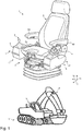
- FIG. 1 shows a vehicle seat 1 for a vehicle V shown in this case as an excavator with a seat part 2 and with a backrest part 3, wherein the seat part (2) and / or the backrest part 3 is adjustable with respect to a degree of inclination.
- the seat part 2 comprises a seat cushion part 2a and a seat part frame 2b.
- the one switching console element 4 is on the seat part frame 2b (see Fig. 3a ) and laterally mounted in this case from the view of the user of the vehicle seat 1, not shown, left of the seat part 2.
- the other switching console element 7 is attached to a seat part frame 2b (see FIG Fig. 3a ) of the seat part 2 and laterally mounted in this case from the view of the user of the vehicle seat 1, not shown, to the right of the seat part 2.
- Both switching console elements have a relation to the vehicle seat 1 which is identical in relation to a displacement in the longitudinal direction 1 x and are in particular in accordance with FIGS. 1 . 2a . 2 B and 2c shown in a basic position.
- the present Fig. 2c shows that only the switching console element 4 is provided with its own locking device (see description below with respect to the locking bolt element 15). Furthermore, the switching console element 7 by means of a transmission system 20 (see in particular Fig. 3c ) is coupled to the shift console element 4. In the present case, the transmission system 20 is suitable for transmitting the sliding movement described above and the locking from one switching console element 4 to the other 7.
- the transmission system 20 is designed free of electronic components and in this example exclusively mechanically in the form of a further Bowden cable system.
- the Bowden cable system 20 in this example comprises a first Bowden cable 21, which is respectively connected directly to the front end 4a1 of the first portion 4a of the first shift console element 4 and the rear end 7a2 of the first portion 7a of the second shift console element 7, and a second Bowden cable 22nd which is respectively directly connected to the front end 7a1 of the first portion 7a of the second shift console element 7 and to the rear end 4a2 of the first portion 4a of the first shift console element 4 (see in particular Fig. 2c ).
- the shift console element 4 comprises a control lever carrier with a housing 9, which serves in particular for the storage of the control lever element 5 and for the protection of signal lines to the control lever element.
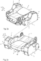
- the Fig. 3b shows, for example, a first portion 4 a of the shift console element 4, which is designed to be displaceable at least in the longitudinal direction 1 x of the vehicle seat 1.
- the vehicle seat 1 in this example comprises two armrests 60.
- the control panel member 4 is formed independently of both armrests 60.
- the control console element 4 does not form any mechanical interaction with the armrest 60.
- a movement (displacement and / or pivoting) of the control panel member 4 is independent of a movement (displacement and / or pivoting) of the armrest 60 feasible; this applies in the present case also vice versa.
- the Fig. 3a shows only a second portion 4b of the switching console element 4, but not the first portion 4a. It is shown that the switching console element 4 has the second section 4b directly and rigidly connected to the seat part frame 2b. In contrast to this, the first section 4 a is designed to be displaceable in the longitudinal direction 1 x of the vehicle seat 1 by means of a displacement movement.
- the switching console element 4 at least in sections, in particular a portion 42 of the first portion 4 a of the switching console element 4, with respect to a degree of inclination again independently of the seat part 2 is adjustable.
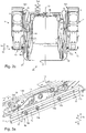
- Fig. 3b shows that the second portion 4b of the switching console element 4, a guide rail member 11 and the first portion 4a of the switching console element 4 comprises a relative to the guide rail member 11 by means of the sliding movement movable slide member 12.
- the guide rail member 11 and the carriage member 12 are slidably mounted to each other.
- the guide rail element 11 and the slide element 12 with respect to their longitudinal extension in the longitudinal 1x and height direction 1z of the vehicle seat 1 extending arranged. Furthermore, the guide rail element 11 and the slide element 12 are each arranged with respect to their longitudinal extent parallel to the longitudinal direction of the vehicle seat 1 x 1.
- the second section 4b of the control console element 4 in the present case comprises three standoffs 13 which are each detachable with a first end 13a fixed to the seat subframe 2b and to a second end 13b are connected to the guide rail element 11 (see in particular Fig. 3a ).
- the guide rail element is placed on the spacer bolts and fastened by means of a respective collar nut.
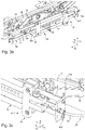
- a mechanical stop element 14 is provided on a first and in the longitudinal direction 1 x front end 11 a and a second and in the longitudinal direction 1 x rear end 11 b of the guide rail element 11, which is intended for the sliding movement of the carriage element 12 with respect to the guide rail element 11 Slide element 12 form a mechanical interaction.
- the stop element 14 is detachably connected to the first 11 a and the second end 11 b of the guide rail element 11.
- a plurality of connecting elements in the form of locating bores are respectively arranged on the first 11a and on the second end 11b of the guide rail element 11 for arranging the stop element, which is designed as a screw.
- the first portion 4a of the shift console element 4 has a seat 41 in the seat width direction 1y portion 41, on which a first shaft 8a is mounted, and about the first shaft 8a pivotable in the seat width direction 1y outer portion 42.
- the central axis 8a1 of the first shaft 8a is presently arranged parallel to the seat width direction 1y.
- the first shaft 8a is arranged at a rear end of the switching console element 4 and axially secured relative to the inner portion 41 by means of a clamping screw 46 and axially relative to the housing 9 by means of two outer locking rings 47 (only one shown).
- a second shaft (not shown) is arranged at the front end of the shift console element 4 as part of the bearing of the front end of the shift console element 4, whose bearing relative to the inner portion 41 and / or the housing 9, for example, identical to the storage of the first shaft 8a configured is.
- a holding element (not shown) is arranged at the front end of the shift console element 4, which provides a holding force by means of which the shift console element 4 with respect to a pivoting around the first shaft 8a in position durable.
- the degree of inclination of the second portion 4b and the portion 41 of the first portion 4a is thus dependent only on a degree of inclination of the seat part 2.
- the degree of inclination of the portion 42 of the first portion 4a is further dependent on the degree of tilt of the seat part 2 on the one hand, and on the other hand on a degree of pivoting of the portion 42 by the portion 41.
- FIGS. 5a and 5b shows that in the present case, the sliding movement of the carriage member 12 relative to the guide rail member 11 is lockable.
- the Fig. 5b shows a cross-sectional view along the line AA Fig. 5a , It is shown that on the guide rail element 11, a mechanical securing element 15 is arranged, which is engageable with the carriage member 12 and is adapted to block the sliding movement of the carriage member 12 relative to the guide rail member 11.
- this securing element 15 ' is designed as a latching pin element 15. This is arranged with respect to its central axis 15a perpendicular to the guide rail member 11 in a complementary recess to him.
- the latching pin element 15 preferably has an outer sleeve element 15b, which has at least no translational degrees of freedom relative to the guide rail element 11, in other words, in the present case in the direction of the central axis 15a of the latching pin element 15, not displaceable relative to the guide rail element 11b.
- a latching pin 15c is displaceably mounted in the direction of the central axis 15a of the latching pin element 15.
- the outer sleeve member 15b has no mechanical interaction with the carriage member 12, by means of a displacement of the locking bolt 15c in the direction of the central axis 15a of the locking pin member 15 toward the carriage member 12, a mechanical interaction between the locking pin 15c and the carriage member 12 can be formed.
- the locking pin 15c in one of a plurality of holes 18 can be inserted on the carriage element 12.
- present the holes 18 are arranged in the longitudinal direction of the carriage member 12, wherein two adjacent holes are each spaced identically to each other.
- a displacement of the latching bolt 15c within the sleeve element 15b can be formed in the present case in that an end of the latching bolt 15c facing away from the carriage element 12 is connected to a Bowden cable element 15d. Furthermore, a lever 15e which can be operated by a user of the vehicle seat 1 (see in particular FIG Fig. 2b and 2c ) is arranged on the vehicle seat 1, which is connected via the Bowden cable element 15d with the locking pin 15c.
- a core 15f of the Bowden cable element 15d which is designed in particular as a wire rope, is loaded in tension, and the locking pin 15c slides out of a bore 18 on carriage element 12 out. Subsequently, the displacement of the carriage element 12 relative to the guide rail element 11 can take place.
- the core 15f is loaded under pressure, and the locking pin 15c can slide into another bore 18 on the carriage element 12.
- a not shown adjusting element in the form of an adjusting screw is arranged on the lever 15e, by means of which a bias of the core 15f is variable.
- the locking pin 15c is spring-loaded relative to the outer sleeve 15b, wherein a force of a spring (not shown), for example, in the cavity 15g between the outer surface of the locking bolt 15c and the inner surface of the outer sleeve 15b stored spring of the locking pin 15c acts in the direction of the carriage member 12.
- An outer shell 15h of the Bowden cable element 15d, within which the core 15f of the Bowden cable element 15d is slidably mounted, is advantageously fastened to the seat base 2b, for example by means of a retaining plate 19a and a clamping screw 19b, so that the position of the outer shell 15h is fixed relative to the seat base 2b is.
Landscapes
- Engineering & Computer Science (AREA)
- Mechanical Engineering (AREA)
- Aviation & Aerospace Engineering (AREA)
- Transportation (AREA)
- General Engineering & Computer Science (AREA)
- Human Computer Interaction (AREA)
- Civil Engineering (AREA)
- Mining & Mineral Resources (AREA)
- Structural Engineering (AREA)
- Physics & Mathematics (AREA)
- Fluid Mechanics (AREA)
- Health & Medical Sciences (AREA)
- Oral & Maxillofacial Surgery (AREA)
- Seats For Vehicles (AREA)
Abstract
Description
- Die Erfindung betrifft einen Fahrzeugsitz für ein Fahrzeug gemäß dem Oberbegriff des Patentanspruches 1.
- Derartige Fahrzeugsitze umfassen generell ein Sitzteil mit einem Sitzteilrahmen und ein Rückenlehnenteil.
- Außerdem umfassen derartige Fahrzeugsitze mindestens ein, bevorzugt zwei Schaltkonsolenelemente, wobei eines der Schaltkonsolenelemente an einer linken und eines an einer rechten Seite des Sitzteils angeordnet sind. Ein derartiges Schaltkonsolenelement umfasst mindestens ein Steuerelement zur Ansteuerung mindestens einer Funktion mindestens eines Aktorelements des Fahrzeugs. Beispielsweise ist das Steuerelement als Handhebel oder Steuerknüppel ("Joystick") ausgestaltet. Beispielsweise wird mittels des Steuerelements eine Bewegung einer Baggerschaufel eines als Bagger ausgestalteten Fahrzeugs oder der Gabel eines als Gabelstapler ausgestalteten Fahrzeugs angesteuert.
- Damit die Bedürfnisse unterschiedlicher Fahrer mit unterschiedlichem Körperbau erfüllt werden können, ist oft das Sitzteil und/ oder das Rückenlehnenteil hinsichtlich eines Neigungsgrades verstellbar ausgebildet. Zusätzlich ist oft eine Verstellung zumindest des Sitzteils in Längsrichtung des Fahrzeugsitzes möglich.
- Aufgabe der vorliegenden Erfindung ist es daher, einen Fahrzeugsitz zur Verfügung zu stellen, bei welchem das Schaltkonsolenelement in allen denkbaren Positionen bzw. Neigungsgraden des Rückenlehnenteils und des Sitzteils sowie für alle potentiellen Fahrer gut erreichbar ist.
- Die Aufgabe der Erfindung wird gelöst von einem Fahrzeugsitz für ein Fahrzeug mit einem Sitzteil, umfassend einen Sitzteilrahmen, und mit einem Rückenlehnenteil, wobei das Sitzteil und/ oder das Rückenlehnenteil hinsichtlich eines Neigungsgrades verstellbar ausgebildet ist, und mit mindestens einem Schaltkonsolenelement, aufweisend mindestens ein Steuerelement zur Ansteuerung mindestens einer Funktion mindestens eines Aktorelements des Fahrzeugs, wobei das Schaltkonsolenelement am Sitzteilrahmen seitlich des Sitzteils montiert ist, wobei ein erster Abschnitt des Schaltkonsolenelements zumindest in Längsrichtung des Fahrzeugsitzes verschiebbar ausgebildet ist.
- Das Schaltkonsolenelement folgt also durch die Verbindung mit dem Sitzteilrahmen bevorzugt einer Bewegung und/ oder einer Verschwenkung des Sitzteils. Gleichzeitig ist ein erster Abschnitt des Schaltkonsolenelements hinsichtlich seiner Relativposition in Längsrichtung des Fahrzeugsitzes einstellbar und somit stets gut erreichbar.
- Es ist denkbar, dass der Fahrzeugsitz weiterhin mindestens eine Armlehne umfasst. In diesem Fall ist es bevorzugt, dass das Steuerkonsolenelement unabhängig von der mindestens einen Armlehne ausgebildet ist. Unabhängig ausgebildet heißt beispielsweise, dass das Steuerkonsolenelement keinerlei mechanische Wechselwirkung mit der Armlehne ausbildet. Unabhängig ausgebildet heißt ferner beispielsweise, dass eine Bewegung (Verschiebung und/ oder Verschwenkung) des Steuerkonsolenelements unabhängig von einer Bewegung (Verschiebung und/ oder Verschwenkung) der Armlehne durchführbar ist; bevorzugt gilt dies auch oder nur umgekehrt.
- Um bei der Montage des Schaltkonsolenelements am Fahrzeugsitz vorhandene Elemente optimal auszunutzen, ist es bevorzugt, dass das Schaltkonsolenelement einen unmittelbar und starr mit dem Sitzteilrahmen verbundenen zweiten Abschnitt aufweist, gegenüber welchem der erste Abschnitt zumindest in Längsrichtung des Fahrzeugsitzes mittels einer Verschiebebewegung verschiebbar ausgebildet ist.
- Es ist also bevorzugt, dass das gesamte Schaltkonsolenelement durch die starre Verbindung seines zweiten Abschnitts mit dem Sitzteilrahmen stets der Verschwenkung des Sitzteils folgt.
- Um die Verschiebebewegung zwischen dem ersten Abschnitt und dem zweiten Abschnitt des Schaltkonsolenelements möglichst sicher und reibungsarm zu gestalten, ist es bevorzugt, dass der zweite Abschnitt des Schaltkonsolenelements ein Führungsschienenelement und der erste Abschnitt des Schaltkonsolenelements ein zum Führungsschienenelement mittels der Verschiebebewegung relativbewegliches Schlittenelement umfasst. Es ist möglich, dass das Führungsschienenelement und das Schlittenelement zueinander gleit- und/ oder wälzgelagert sind.
- Bevorzugt sind das Führungsschienenelement und das Schlittenelement hinsichtlich ihrer Längsausdehnung sich in Längs- und/ oder Höhenrichtung des Fahrzeugsitzes erstreckend angeordnet. Weiter bevorzugt sind das Führungsschienenelement und das Schlittenelement hinsichtlich ihrer Längsausdehnung jeweils parallel zur Längsrichtung des Fahrzeugsitzes angeordnet.
- Um die starre Verbindung zwischen dem Sitzteilrahmen und dem zweiten Abschnitt des Schaltkonsolenelements auszubilden, hat es sich als vorteilhaft herausgestellt, wenn der zweite Abschnitt des Schaltkonsolenelements Abstandsbolzen umfasst, welche jeweils mit einem ersten Ende starr mit dem Sitzteilrahmen und mit einem zweiten Ende lösbar mit dem Führungsschienenelement verbunden sind.
- Es können beispielsweise an diesem Sitzunterbau mindestens zwei, bevorzugt drei Abstandsbolzen verschweißt sein. Um eine plane Auflagefläche des Führungsschienenelements an allen drei Abstandsbolzen zu garantieren, können diese Abstandsbolzen vor dem Verschweißen auf einer Montageplatte befestigt sein. Im Anschluss daran kann das Führungsschienenelement auf die Abstandsbolzen gesteckt und beispielsweise mittels je einer Bundmutter befestigt werden.
- Am Schlittenelement können beispielsweise je zwei Halter für Steuerhebelträger montiert werden, an welchen die Steuerhebelträger montiert werden.
- Um die Verschiebebewegung des Schlittenelements gegenüber dem Führungsschienenelement begrenzen zu können, ist es vorteilhaft, wenn an einem ersten und einem zweiten Ende des Führungsschienenelements jeweils ein mechanisches Anschlagelement angeordnet ist, welches dafür vorgesehen ist, bei der Verschiebebewegung des Schlittenelements gegenüber dem Führungsschienenelement mit dem Schlittenelement eine mechanische Wechselwirkung auszubilden.
- Bevorzugt ist das Anschlagelement lösbar mit dem ersten und dem zweiten Ende des Führungsschienenelements verbunden. Bevorzugt sind zur Anordnung des Anschlagelements, welches beispielsweise als Schraube ausgestaltet ist, am ersten und am zweiten Ende des Führungsschienenelements jeweils mindestens zwei Verbindungselemente, welche insbesondere in Form von Aufnahmebohrungen ausgestaltet sind, angeordnet. Denkbar wäre auch, dass Verbindungselemente über die gesamte Länge des Führungsschienenelements angeordnet sind, bevorzugt in regelmäßigen Abständen von beispielsweise 10 mm zueinander.
- Gemäß einem besonders bevorzugten Ausführungsbeispiel ist es vorgesehen, dass der erste Abschnitt des Schaltkonsolenelements einen in Sitzbreitenrichtung innen liegenden Anteil, an welchem eine erste Welle gelagert ist, und einen um die erste Welle verschwenkbaren in Sitzbreitenrichtung außen liegenden Anteil aufweist. Insbesondere ist also der außen liegende Anteil des ersten Abschnitts des Schaltkonsolenelements hinsichtlich eines Neigungsgrades verstellbar, bevorzugt hinsichtlich eines Neigungsgrades um die Sitzbreitenrichtung. Dem Fachmann ist bewusst, dass mittels der beschriebenen Lagerung mit der Verschwenkung um die erste Welle nicht nur eine Änderung des Neigungsgrades des außen liegenden Anteils, sondern auch eine Änderung der Position des außen liegenden Anteils in Höhenrichtung des Fahrzeugsitzes einhergeht.
- Der Neigungsgrad des zweiten Abschnitts des Schaltkonsolenelements sowie des innen liegenden Anteils des ersten Abschnitts ist also bevorzugt lediglich von einem Neigungsgrad des Sitzteils abhängig. Der Neigungsgrad des außen liegenden Anteils des ersten Abschnitts des Schaltkonsolenelements ist dagegen bevorzugt zum einen vom Neigungsgrad des Sitzteils und zum anderen von einem Verschwenkungsgrad des außen liegenden Anteils um den innen liegenden Anteil abhängig. Somit ist bevorzugt eine Grobjustierung des Neigungsgrades des außen liegenden Anteils über den Neigungsgrad des Sitzteils sowie eine Feinjustierung über den Verschwenkungsgrad des außen liegenden Anteils um den innen liegenden Anteil möglich.
- Die Längsposition des zweiten Abschnitts des Schaltkonsolenelements ist ferner bevorzugt lediglich von einer Längsposition des Sitzteils abhängig. Die Längsposition des ersten Abschnitts des Schaltkonsolenelements ist dagegen bevorzugt zum einen von der Längsposition des Sitzteils und zum anderen von einem Grad der Verschiebung des ersten Abschnitts gegenüber dem zweiten Abschnitt des Schaltkonsolenelements abhängig.
- Besonders bevorzugt ist eine Mittelachse der ersten Welle parallel zur Sitzbreitenrichtung angeordnet. Weiterhin bevorzugt ist die erste Welle an einem hinteren Ende des Schaltkonsolenelements angeordnet, so dass insbesondere von allen Kompartimenten des außen liegenden Anteils des ersten Abschnitts des Schaltkonsolenelements ein vorderes Kompartiment während der Verschwenkbewegung um die erste Welle eine größtmögliche Änderung des Neigungsgrades erfährt. Damit ist es möglich, bereits mit einer Verschwenkung um einen geringen Winkel eine große Neigungs- und Höhenverstellung des vorderen Kompartiments zu erzielen.
- An dem außen liegenden Anteil und bevorzugt an dem vorderen Kompartiment ist vorteilhaft das Steuerelement angeordnet, so dass dieses ebenfalls die größtmögliche Änderung des Neigungsgrades erfährt und sich also besonders schnell auf die gewünschte Neigung und damit auch auf die gewünschte Höhe einstellen lässt. Ebenfalls lässt sich der Neigungsgrad über die oben erwähnte Grob- und Feinjustierung relativ genau einstellen.
- Besonders bevorzugt ist am vorderen Ende des Schaltkonsolenelements eine zweite Welle als Teil der Lagerung des vorderen Endes des Schaltkonsolenelements angeordnet. Beispielsweise ist eine Mittelachse der zweiten Welle parallel zur Sitzbreitenrichtung angeordnet.
- Besonders bevorzugt ist am vorderen Ende des Schaltkonsolenelements ein Halteelement angeordnet, welches eine Haltekraft bereitstellt, mittels welcher das Schaltkonsolenelement hinsichtlich einer Verschwenkung um die erste Welle in Position haltbar ist. Dieses Halteelement ist insbesondere als Gasdruckfederelement ausgestaltet und/ oder mit der zweiten Welle verbunden. Eine Verschwenkung des Schaltkonsolenelements um die erste Welle erfolgt also bevorzugt manuell und/ oder in Richtung oder entgegen der Haltekraft des Halteelements.
- Es ist bevorzugt, dass die erste und/ oder die zweite Welle gegenüber dem in Sitzbreitenrichtung innen liegenden Anteil keinen Freiheitsgrad in radialer und/ oder axialer Richtung aufweisen. Beispielsweise ist der radiale Freiheitsgrad gesperrt, indem eine Klemmschraube senkrecht zur Mittelachse der ersten und/ oder zweiten Welle am innen liegenden Anteil angeordnet ist, deren Schaft mittels seiner Stirnfläche radial außen an der ersten und/ oder der zweiten Welle anliegt und somit die Drehung der jeweiligen Welle um ihre Mittelachse sperrt. Beispielsweise ist der axiale Freiheitsgrad durch die Verwendung zweier Außensicherungsringe, welche auf einem Außendurchmesser der jeweiligen Welle und zu beiden Seiten des in Sitzbreitenrichtung außen liegenden Anteil angeordnet sind, gesperrt.
- Ebenfalls bevorzugt ist die Verschiebebewegung des Schlittenelements gegenüber dem Führungsschienenelement sperrbar; insbesondere ist also nach erfolgter Verschiebung in Längsrichtung die gewünschte Relativposition des Schlittenelements gegenüber dem Führungsschienenelement arretierbar. Dazu ist es vorteilhaft, wenn am Führungsschienenelement ein mechanisches Sicherungselement angeordnet ist, welches in Eingriff mit dem Schlittenelement bringbar ist und dazu ausgebildet ist, die Verschiebebewegung des Schlittenelements gegenüber dem Führungsschienenelement zu sperren.
- Beispielsweise ist dieses Sicherungselement als Rastbolzenelement ausgestaltet. Dieses ist beispielsweise in Bezug auf seine Mittelachse senkrecht zum Führungsschienenelement in einer zu ihm komplementären Aussparung angeordnet. Das Rastbolzenelement weist bevorzugt ein äußeres Hülsenelement auf, welches gegenüber dem Führungsschienenelement zumindest keine translatorischen Freiheitsgrade aufweist, mit anderen Worten ist es also, bevorzugt in Richtung der Mittelachse des Rastbolzenelements, nicht verschieblich gegenüber dem Führungsschienenelement angeordnet. Innerhalb des äußeren Hülsenelements ist ein Rastbolzen in Richtung der Mittelachse des Rastbolzenelements verschieblich gelagert.
- Während das äußere Hülsenelement bevorzugt keine mechanische Wechselwirkung mit dem Schlittenelement aufweist, ist bevorzugt mittels einer Verschiebung des Rastbolzens in Richtung der Mittelachse des Rastbolzenelements hin zum Schlittenelement eine mechanische Wechselwirkung zwischen dem Rastbolzen und dem Schlittenelement ausbildbar. Bevorzugt ist der Rastbolzen in eine von mindestens zwei Bohrungen am Schlittenelement einführbar. Besonders bevorzugt sind die mindestens zwei Bohrungen in Längsrichtung des Schlittenelements angeordnet. Wenn es mehr als zwei Bohrungen sind, sind zwei benachbarte Bohrungen bevorzugt jeweils identisch zueinander beabstandet.
- Eine Verschiebung des Rastbolzens innerhalb des Hülsenelements ist bevorzugt ausbildbar, indem ein dem Schlittenelement abgewandtes Ende des Rastbolzens mit einem weiteren, auf Zug und Druck belastbaren Bowdenzugelement verbunden ist. Ferner ist bevorzugt ein mittels eines Benutzers des Fahrzeugsitzes bedienbarer Hebel am Fahrzeugsitz angeordnet, welcher über das weitere Bowdenzugelement mit dem Rastbolzen verbunden ist.
- Auf Zug beanspruchbar oder belastbar heißt, dass das jeweilige Element dazu ausgebildet ist, Zugkräfte zu übertragen. Auf Druck beanspruchbar heißt, dass das jeweilige Element dazu ausgebildet ist, Druckkräfte zu übertragen.
- Verschwenkt oder verschiebt der Benutzer den Hebel in eine erste Richtung, so ist eine Seele des weiteren Bowdenzugelements, welche insbesondere als ein Drahtseil ausgestaltet ist, auf Zug belastet, und der Rastbolzen gleitet aus einer Bohrung am Schlittenelement heraus. Anschließend kann die Verschiebung des Schlittenelements gegenüber dem Führungsschienenelement erfolgen.
- Verschwenkt oder verschiebt der Benutzer den Hebel in eine zweite Richtung, so ist die Seele auf Druck belastet, und der Rastbolzen kann in eine andere Bohrung am Schlittenelement hineingleiten. Besonders bevorzugt ist am Hebel ein Verstellelement, beispielsweise in Form einer Stellschraube angeordnet, mittels welchem eine Vorspannung der Seele veränderbar ist.
- Zusätzlich oder alternativ kann der Rastbolzen gegenüber der äußeren Hülse federgelagert sein, wobei die Kraft einer Feder der Federlagerung dazu geeignet ist, den Rastbolzen in Richtung des Schlittenelements zu bewegen.
- Eine äußere Hülle des weiteren Bowdenzugelements (auch Zughülle oder Bogen genannt), innerhalb welcher die Seele des weiteren Bowdenzugelements verschieblich gelagert ist, ist vorteilhaft am Sitzunterbau befestigt, beispielsweise mittels eines Halteblechs und einer Klemmschraube, so dass die Position der äußeren Hülle gegenüber dem Sitzunterbau fest ist.
- Gemäß einer bevorzugten Ausführungsvariante ist es ferner vorgesehen, dass eines der Schaltkonsolenelemente eine Verschiebung wie oben beschrieben erfährt, indem der Benutzer die Arretierung löst und das Schaltkonsolenelement manuell verschiebt. Es kann möglich sein, dass das andere der Schaltkonsolenelemente ebenfalls eine eigene Verschiebung wie oben beschrieben erfährt und dementsprechend auch mit einer eigenen Arretierungsvorrichtung versehen ist.
- Zugunsten einer höheren Kosteneffizienz ist es jedoch bevorzugt, dass nur das eine der Schaltkonsolenelemente mit einer eigenen Arretierungsvorrichtung versehen ist. Ferner ist es bevorzugt vorgesehen, dass das andere der Schaltkonsolenelemente mittels eines Übertragungssystems mit dem einen der Schaltkonsolenelemente gekoppelt ist. Bevorzugt ist das Übertragungssystem geeignet, die oben beschriebene Verschiebebewegung und/ oder die Arretierung von dem einen Schaltkonsolenelement auf das andere zu übertragen. Außerdem ist es bevorzugt, wenn das Übertragungssystem frei von elektronischen Komponenten ist.
- Im Sinne der vorliegenden Erfindung wird unter dem Begriff "frei von elektronischen Komponenten" verstanden, dass das jeweilige Element, in diesem Falle das Übertragungssystem, ohne jegliche Komponente auskommt, die ein Fachmann als Elektronikkomponente ansehen würde; insbesondere sind solche Elektronikkomponenten beispielsweise als Sensoren, Kontakte, Steuerungen, Schalter, Relais, Dioden, Lichtschranken etc. ausgebildet. Somit ist das Übertragungssystem beispielsweise ausschließlich mechanisch oder mechanisch und pneumatisch oder mechanisch und hydraulisch ausgestaltet.
- Vorteile und Zweckmäßigkeiten sind der nachfolgenden Beschreibung in Verbindung mit der Zeichnung zu entnehmen.
- Es zeigen:
- Fig. 1
- eine perspektivische Ansicht eines erfindungsgemäßen Fahrzeugsitzes;
- Fig. 2a-2c
- verschiedene Ansichten eines Sitzteils des Fahrzeugsitzes gemäß
Fig. 1 mit Teilen zweier Schaltkonsolenelemente; - Fig. 3a-3f
- verschiedene Ansichten des Sitzunterbaus des Sitzteils gemäß den
Figuren 2a-2c mit dem Führungsschienenelement und dem Schlittenelement des Schaltkonsolenelements; - Fig. 4
- eine perspektivische Ansicht des Schaltkonsolenelements mit der ersten Welle;
- Fig. 5a, 5b
- verschiedene Ansichten der Arretiervorrichtung zwischen dem Führungsschienenelement und dem Schlittenelement des Schaltkonsolenelements.
- Es sei darauf hingewiesen, dass in den Figuren zum Teil Komponenten nicht dargestellt sind, um die Übersichtlichkeit zu gewähren. Beispielsweise zeigen die
Figuren 2a-c kein Steuerhebelelement 5 und dieFiguren 3a-f nur Teile des Schaltkonsolenelements 4. - Die
Figur 1 zeigt demnach einen Fahrzeugsitz 1 für ein in diesem Fall als Bagger dargestelltes Fahrzeug V mit einem Sitzteil 2 und mit einem Rückenlehnenteil 3, wobei das Sitzteil (2) und/ oder das Rückenlehnenteil 3 hinsichtlich eines Neigungsgrades verstellbar ausgebildet ist. Ferner sind in diesem Beispiel zwei Schaltkonsolenelemente 4, 7, aufweisend jeweils ein Steuerelement 5 in Form eines Joysticks zur Ansteuerung mindestens einer Funktion mindestens eines Aktorelements 6 (hier in Form eines Motors zur Bewegung eines Baggerschaufelarms des Fahrzeugs V) am Fahrzeugsitz 1 angeordnet. - Gezeigt ist ferner in allen
Figuren 1-5b ein Koordinatensystem mit der Längsrichtung 1x mit nach vorne weisender Pfeilspitze, der Breitenrichtung 1y mit nach rechts weisender Pfeilspitze sowie der Höhenrichtung 1z des Fahrzeugsitzes 1 mit nach oben weisender Pfeilspitze, jeweils aus Sicht eines nicht dargestellten Benutzers des Fahrzeugsitzes 1. - Das Sitzteil 2 umfasst vorliegend ein Sitzpolsterteil 2a und einen Sitzteilrahmen 2b. Das eine Schaltkonsolenelement 4 ist am Sitzteilrahmen 2b (siehe
Fig. 3a ) und seitlich, in diesem Fall aus Sicht des nicht dargestellten Benutzers des Fahrzeugsitzes 1 links des Sitzteils 2 montiert. Das andere Schaltkonsolenelement 7 ist an einem Sitzteilrahmen 2b (sieheFig. 3a ) des Sitzteils 2 und seitlich, in diesem Fall aus Sicht des nicht dargestellten Benutzers des Fahrzeugsitzes 1 rechts des Sitzteils 2 montiert. Beide Schaltkonsolenelemente weisen eine in Bezug auf eine Verschiebung in Längsrichtung 1x identische Relativposition gegenüber dem Fahrzeugsitz 1 auf und sind insbesondere gemäß derFiguren 1 ,2a ,2b und2c in einer Grundstellung gezeigt. - Die vorliegende
Fig. 2c zeigt, dass nur das Schaltkonsolenelement 4 mit einer eigenen Arretierungsvorrichtung (siehe Beschreibung unten bezüglich des Rastbolzenelements 15) versehen ist. Ferner ist das Schaltkonsolenelement 7 mittels eines Übertragungssystems 20 (siehe insbesondereFig. 3c ) mit dem Schaltkonsolenelement 4 gekoppelt. Vorliegend ist das Übertragungssystem 20 geeignet, die oben beschriebene Verschiebebewegung und die Arretierung von dem einen Schaltkonsolenelement 4 auf das andere 7 zu übertragen. - Außerdem ist vorliegend das Übertragungssystem 20 frei von elektronischen Komponenten und in diesem Beispiel ausschließlich mechanisch in Form eines weiteren Bowdenzugsystems ausgestaltet. Das Bowdenzugsystem 20 umfasst in diesem Beispiel einen ersten Bowdenzug 21, welcher jeweils unmittelbar mit dem vorderen Ende 4a1 des ersten Abschnitts 4a des ersten Schaltkonsolenelements 4 und mit dem hinteren Ende 7a2 des ersten Abschnitts 7a des zweiten Schaltkonsolenelements 7 verbunden ist, und einen zweiten Bowdenzug 22, welcher jeweils unmittelbar mit dem vorderen Ende 7a1 des ersten Abschnitts 7a des zweiten Schaltkonsolenelements 7 und mit dem hinteren Ende 4a2 des ersten Abschnitts 4a des ersten Schaltkonsolenelements 4 verbunden ist (siehe hierzu insbesondere
Fig. 2c ). - Die nun folgende Beschreibung bezieht sich, wenn nicht anders angegeben, stets auf das links des Sitzteils 2 montierte Schaltkonsolenelement 4. Dem Fachmann ist selbstverständlich klar, dass die folgenden Merkmale und Beschreibungen analog auch für das rechts des Sitzteils 2 montierte Schaltkonsolenelement 7 gelten können.
- Das Schaltkonsolenelement 4 umfasst einen Steuerhebelträger mit einem Gehäuse 9, welches insbesondere zur Lagerung des Steuerhebelelements 5 sowie zum Schutz von Signalleitungen zum Steuerhebelelement hin dient.
- Die
Fig. 3b zeigt beispielsweise einen ersten Abschnitt 4a des Schaltkonsolenelements 4, welcher zumindest in Längsrichtung 1x des Fahrzeugsitzes 1 verschiebbar ausgebildet ist. - Gezeigt ist, dass der Fahrzeugsitz 1 in diesem Beispiel zwei Armlehnen 60 umfasst. In diesem Fall ist das Steuerkonsolenelement 4 unabhängig von beiden Armlehnen 60 ausgebildet ist. Das Steuerkonsolenelement 4 bildet vorliegend keinerlei mechanische Wechselwirkung mit der Armlehne 60 aus. Ferner ist eine Bewegung (Verschiebung und/ oder Verschwenkung) des Steuerkonsolenelements 4 unabhängig von einer Bewegung (Verschiebung und/ oder Verschwenkung) der Armlehne 60 durchführbar; es gilt dies vorliegend auch umgekehrt.
- Die
Fig. 3a zeigt nur einen zweiten Abschnitt 4b des Schaltkonsolenelements 4, nicht aber den ersten Abschnitt 4a. Gezeigt ist, dass das Schaltkonsolenelement 4 den unmittelbar und starr mit dem Sitzteilrahmen 2b verbundenen zweiten Abschnitt 4b aufweist. Diesem gegenüber ist der erste Abschnitt 4a in Längsrichtung 1x des Fahrzeugsitzes 1 mittels einer Verschiebebewegung verschiebbar ausgebildet. - Vorliegend ist also gewährleistet, dass zumindest der zweite Abschnitt 4b durch die starre Verbindung mit dem Sitzteilrahmen 2b stets der Verschwenkung des Sitzteils 2 folgt. Wie weiter unten noch erläutert wird, ist es jedoch bevorzugt, dass das Schaltkonsolenelement 4 zumindest abschnittsweise, insbesondere nämlich ein Anteil 42 des ersten Abschnitts 4a des Schaltkonsolenelements 4, hinsichtlich eines Neigungsgrades nochmals unabhängig vom Sitzteil 2 verstellbar ist.
- Insbesondere die
Fig. 3b zeigt, dass der zweite Abschnitt 4b des Schaltkonsolenelements 4 ein Führungsschienenelement 11 und der erste Abschnitt 4a des Schaltkonsolenelements 4 ein zum Führungsschienenelement 11 mittels der Verschiebebewegung relativbewegliches Schlittenelement 12 umfasst. In diesem Beispiel sind das Führungsschienenelement 11 und das Schlittenelement 12 zueinander gleitgelagert. - Vorliegend sind das Führungsschienenelement 11 und das Schlittenelement 12 hinsichtlich ihrer Längsausdehnung sich in Längs- 1x und Höhenrichtung 1z des Fahrzeugsitzes 1 erstreckend angeordnet. Ferner sind das Führungsschienenelement 11 und das Schlittenelement 12 hinsichtlich ihrer Längsausdehnung jeweils parallel zur Längsrichtung 1x des Fahrzeugsitzes 1 angeordnet.
- Um die starre Verbindung zwischen dem Sitzteilrahmen 2b und dem zweiten Abschnitt 4b des Schaltkonsolenelements 4 auszubilden, umfasst der zweite Abschnitt 4b des Schaltkonsolenelements 4 vorliegend drei Abstandsbolzen 13, welche jeweils mit einem ersten Ende 13a starr mit dem Sitzteilrahmen 2b und mit einem zweiten Ende 13b lösbar mit dem Führungsschienenelement 11 verbunden sind (siehe insbesondere
Fig. 3a ). Vorliegend ist das Führungsschienenelement auf die Abstandsbolzen gesteckt und mittels je einer Bundmutter befestigt. - Am Schlittenelement 12 sind vorliegend je zwei Halter 16 für den Steuerhebelträger 17 bzw. für das Gehäuse 9 montiert.
- Ferner zeigt die
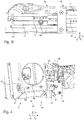
Fig. 3a , dass an einem ersten und in Längsrichtung 1x vorderen Ende 11a und einem zweiten und in Längsrichtung 1x hinteren Ende 11b des Führungsschienenelements 11 jeweils ein mechanisches Anschlagelement 14 angeordnet ist, welches dafür vorgesehen ist, bei der Verschiebebewegung des Schlittenelements 12 gegenüber dem Führungsschienenelement 11 mit dem Schlittenelement 12 eine mechanische Wechselwirkung auszubilden. - Vorliegend ist das Anschlagelement 14 lösbar mit dem ersten 11a und dem zweiten Ende 11b des Führungsschienenelements 11 verbunden. Vorliegend sind zur Anordnung des Anschlagelements, welches vorliegend als Schraube ausgestaltet ist, am ersten 11a und am zweiten Ende 11b des Führungsschienenelements 11 jeweils mehrere Verbindungselemente in Form von Aufnahmebohrungen angeordnet.
- Gemäß der
Fig. 4 ist gezeigt, dass der erste Abschnitt 4a des Schaltkonsolenelements 4 einen in Sitzbreitenrichtung 1y innen liegenden Anteil 41, an welchem eine erste Welle 8a gelagert ist, und den um die erste Welle 8a verschwenkbaren in Sitzbreitenrichtung 1y außen liegenden Anteil 42 aufweist. Die Mittelachse 8a1 der ersten Welle 8a ist vorliegend parallel zur Sitzbreitenrichtung 1y angeordnet. Weiterhin ist die erste Welle 8a an einem hinteren Ende des Schaltkonsolenelements 4 angeordnet und gegenüber dem innen liegenden Anteil 41 mittels einer Klemmschraube 46 radial sowie gegenüber dem Gehäuse 9 mittels zweier Außensicherungsringen 47 (nur einer gezeigt) axial gesichert. - Vorliegend ist am vorderen Ende des Schaltkonsolenelements 4 eine zweite Welle (nicht gezeigt) als Teil der Lagerung des vorderen Endes des Schaltkonsolenelements 4 angeordnet, deren Lagerung gegenüber dem innen liegenden Anteil 41 und/ oder dem Gehäuse 9 beispielsweise identisch zur Lagerung der ersten Welle 8a ausgestaltet ist. Ferner ist am vorderen Ende des Schaltkonsolenelements 4 ein Halteelement (nicht gezeigt) angeordnet, welches eine Haltekraft bereitstellt, mittels welcher das Schaltkonsolenelement 4 hinsichtlich einer Verschwenkung um die erste Welle 8a in Position haltbar ist.
- Der Neigungsgrad des zweiten Abschnitts 4b sowie des Anteils 41 des ersten Abschnitts 4a ist also lediglich von einem Neigungsgrad des Sitzteils 2 abhängig. Der Neigungsgrad des Anteils 42 des ersten Abschnitts 4a ist ferner zum einen vom Neigungsgrad des Sitzteils 2 und zum anderen von einem Verschwenkungsgrad des Anteils 42 um den Anteil 41 abhängig.
- Aus den
Figuren 5a und 5b geht hervor, dass vorliegend die Verschiebebewegung des Schlittenelements 12 gegenüber dem Führungsschienenelement 11 sperrbar ist. DieFig. 5b zeigt dabei eine Querschnittsdarstellung entlang der Linie A-A ausFig. 5a . Gezeigt ist, dass am Führungsschienenelement 11 ein mechanisches Sicherungselement 15 angeordnet ist, welches in Eingriff mit dem Schlittenelement 12 bringbar ist und dazu ausgebildet ist, die Verschiebebewegung des Schlittenelements 12 gegenüber dem Führungsschienenelement 11 zu sperren. - Vorliegend ist dieses Sicherungselement 15' als Rastbolzenelement 15 ausgestaltet. Dieses ist in Bezug auf seine Mittelachse 15a senkrecht zum Führungsschienenelement 11 in einer zu ihm komplementären Aussparung angeordnet. Das Rastbolzenelement 15 weist bevorzugt ein äußeres Hülsenelement 15b auf, welches gegenüber dem Führungsschienenelement 11 zumindest keine translatorischen Freiheitsgrade aufweist, mit anderen Worten ist es also, vorliegend in Richtung der Mittelachse 15a des Rastbolzenelements 15, nicht verschieblich gegenüber dem Führungsschienenelement 11b angeordnet. Innerhalb des äußeren Hülsenelements 15b ist ein Rastbolzen 15c in Richtung der Mittelachse 15a des Rastbolzenelements 15 verschieblich gelagert.
- Während das äußere Hülsenelement 15b keine mechanische Wechselwirkung mit dem Schlittenelement 12 aufweist, ist mittels einer Verschiebung des Rastbolzens 15c in Richtung der Mittelachse 15a des Rastbolzenelements 15 hin zum Schlittenelement 12 eine mechanische Wechselwirkung zwischen dem Rastbolzen 15c und dem Schlittenelement 12 ausbildbar. Vorliegend ist der Rastbolzen 15c in eine von einer Vielzahl an Bohrungen 18 (siehe
Fig. 3b , gemäß der einige der Bohrungen referenziert sind) am Schlittenelement 12 einführbar. Vorliegend sind die Bohrungen 18 in Längsrichtung des Schlittenelements 12 angeordnet, wobei zwei benachbarte Bohrungen jeweils identisch zueinander beabstandet sind. - Eine Verschiebung des Rastbolzens 15c innerhalb des Hülsenelements 15b ist vorliegend ausbildbar, indem ein dem Schlittenelement 12 abgewandtes Ende des Rastbolzens 15c mit einem Bowdenzugelement 15d verbunden ist. Ferner ist ein mittels eines Benutzers des Fahrzeugsitzes 1 bedienbarer Hebel 15e (siehe insbesondere
Fig. 2b und2c ) am Fahrzeugsitz 1 angeordnet, welcher über das Bowdenzugelement 15d mit dem Rastbolzen 15c verbunden ist. - Verschwenkt oder verschiebt der Benutzer den Hebel 15e in eine erste Richtung (vorliegend in Sitzlängsrichtung 1x nach vorne), so ist eine Seele 15f des Bowdenzugelements 15d, welche insbesondere als ein Drahtseil ausgestaltet ist, auf Zug belastet, und der Rastbolzen 15c gleitet aus einer Bohrung 18 am Schlittenelement 12 heraus. Anschließend kann die Verschiebung des Schlittenelements 12 gegenüber dem Führungsschienenelement 11 erfolgen.
- Verschwenkt oder verschiebt der Benutzer den Hebel 15e in eine zweite Richtung (vorliegend in Sitzlängsrichtung 1x nach hinten), so ist die Seele 15f auf Druck belastet, und der Rastbolzen 15c kann in eine andere Bohrung 18 am Schlittenelement 12 hineingleiten. Vorliegend ist am Hebel 15e ein nicht gezeigtes Verstellelement in Form einer Stellschraube angeordnet, mittels welchem eine Vorspannung der Seele 15f veränderbar ist.
- Zusätzlich wäre es denkbar, dass der Rastbolzen 15c gegenüber der äußeren Hülse 15b federgelagert ist, wobei eine Kraft einer beispielsweise in dem Hohlraum 15g zwischen der Außenfläche des Rastbolzens 15c und der Innenfläche der äußeren Hülse 15b gelagerten Feder (nicht gezeigt) der Federlagerung auf den Rastbolzen 15c in Richtung des Schlittenelements 12 wirkt.
- Eine äußere Hülle 15h des Bowdenzugelements 15d, innerhalb welcher die Seele 15f des Bowdenzugelements 15d verschieblich gelagert ist, ist vorteilhaft am Sitzunterbau 2b befestigt, beispielsweise mittels eines Halteblechs 19a und einer Klemmschraube 19b, so dass die Position der äußeren Hülle 15h gegenüber dem Sitzunterbau 2b fest ist.
- Sämtliche in den Anmeldungsunterlagen offenbarten Merkmale werden als erfindungswesentlich beansprucht, sofern sie einzeln oder in Kombination gegenüber dem Stand der Technik neu sind.
-
- 1
- Fahrzeugsitz
- 1x
- Längsrichtung
- 1y
- Breitenrichtung
- 1z
- Höhenrichtung
- 2
- Sitzteil
- 2a
- Sitzfläche
- 2b
- Sitzteilrahmen
- 3
- Rückenlehnenteil
- 4,7
- Schaltkonsolenelement
- 4a, 7a
- erster Abschnitt
- 4a1, 7a1
- vorderes Ende
- 4a2, 7a2
- hinteres Ende
- 4b
- zweiter Abschnitt
- 5
- Steuerelement
- 6
- Aktorelement
- 8a
- Welle
- 8a1
- Mittelachse
- 9
- Gehäuseelement
- 10
- Übertragungssystem
- 11
- Führungsschienenelement
- 11a, 11b
- Ende
- 12
- Schlittenelement
- 13
- Abstandsbolzen
- 13a, 13b
- Ende
- 14
- Anschlagelement
- 15'
- Sicherungselement
- 15
- Rastbolzenelement
- 15a
- Mittelachse
- 15b
- Hülsenelement
- 15c
- Rastbolzen
- 15d
- Bowdenzugelement
- 15e
- Hebel
- 15f
- Seele
- 15g
- Hohlraum
- 15h
- äußere Hülle
- 16
- Halter
- 17
- Steuerhebelträger
- 18
- Bohrung
- 19a
- Halteblech
- 19b
- Klemmschraube
- 20
- Bowdenzugsystem
- 21,22,23
- Bowdenzug
- 30
- Zylindersystem
- 31, 32
- Zylinder
- 41, 42
- Anteil
- 50
- Leitelemente
- 60
- Armlehne
- L, R
- Seite
- V
- Fahrzeug
Claims (7)
- Fahrzeugsitz (1) für ein Fahrzeug (V) mit einem Sitzteil (2), umfassend einen Sitzteilrahmen (2b), und mit einem Rückenlehnenteil (3), wobei das Sitzteil (2) und/ oder das Rückenlehnenteil (3) hinsichtlich eines Neigungsgrades verstellbar ausgebildet ist, und mit mindestens einem Schaltkonsolenelement (4), aufweisend mindestens ein Steuerelement (5) zur Ansteuerung mindestens einer Funktion mindestens eines Aktorelements (6) des Fahrzeugs (V),
dadurch gekennzeichnet, dass
das Schaltkonsolenelement (4) am Sitzteilrahmen (2b) seitlich des Sitzteils (2) montiert ist, wobei ein erster Abschnitt (4a) des Schaltkonsolenelements (4) zumindest in Längsrichtung (1x) des Fahrzeugsitzes (1) verschiebbar ausgebildet ist. - Fahrzeugsitz (1) nach Anspruch 1,
dadurch gekennzeichnet, dass
das Schaltkonsolenelement (4) einen unmittelbar und starr mit dem Sitzteilrahmen (2b) verbundenen zweiten Abschnitt (4b) aufweist, gegenüber welchem der erste Abschnitt (4a) zumindest in Längsrichtung (1x) des Fahrzeugsitzes (1) mittels einer Verschiebebewegung verschiebbar ausgebildet ist. - Fahrzeugsitz (1) nach Anspruch 2,
dadurch gekennzeichnet, dass
der zweite Abschnitt (4b) des Schaltkonsolenelements (4) ein Führungsschienenelement (11) und der erste Abschnitt (4a) des Schaltkonsolenelements (4) ein zum Führungsschienenelement (11) mittels der Verschiebebewegung relativbewegliches Schlittenelement (12) umfasst. - Fahrzeugsitz (1) nach Anspruch 3,
dadurch gekennzeichnet, dass
der zweite Abschnitt (4b) des Schaltkonsolenelements (4) Abstandsbolzen (13) umfasst, welche jeweils mit einem ersten Ende (13a) starr mit dem Sitzteilrahmen (2b) und mit einem zweiten Ende (13b) lösbar mit dem Führungsschienenelement (11) verbunden sind. - Fahrzeugsitz (1) nach einem der Ansprüche 3 oder 4,
dadurch gekennzeichnet, dass
an einem ersten (11a) und einem zweiten Ende (11b) des Führungsschienenelements (11) jeweils ein mechanisches Anschlagelement (14) angeordnet ist, welches dafür vorgesehen ist, bei der Verschiebebewegung des Schlittenelements (12) gegenüber dem Führungsschienenelement (11) mit dem Schlittenelement (12) eine mechanische Wechselwirkung auszubilden. - Fahrzeugsitz (1) nach einem der vorhergehenden Ansprüche,
dadurch gekennzeichnet, dass
der erste Abschnitt (4a) des Schaltkonsolenelements (4) einen in Sitzbreitenrichtung (1y) innen liegenden Anteil (41), an welchem eine erste Welle (8a) gelagert ist, und einen um die erste Welle (8a) verschwenkbaren in Sitzbreitenrichtung (1y) außen liegenden Anteil (42) aufweist. - Fahrzeugsitz (1) nach einem der vorhergehenden Ansprüche,
dadurch gekennzeichnet, dass
am Führungsschienenelement (11) ein mechanisches Sicherungselement (15) angeordnet ist, welches in Eingriff mit dem Schlittenelement (12) bringbar ist und dazu ausgebildet ist, die Verschiebebewegung des Schlittenelements (12) gegenüber dem Führungsschienenelement (11) zu sperren.
Applications Claiming Priority (2)
| Application Number | Priority Date | Filing Date | Title |
|---|---|---|---|
| DE102018108792.6A DE102018108792B4 (de) | 2018-04-13 | 2018-04-13 | Fahrzeugsitz mit gemeinsam verstellbaren Schaltkonsolen |
| DE102018108795.0A DE102018108795B4 (de) | 2018-04-13 | 2018-04-13 | Fahrzeugsitz mit verstellbarer Schaltkonsole |
Publications (2)
| Publication Number | Publication Date |
|---|---|
| EP3552874A1 true EP3552874A1 (de) | 2019-10-16 |
| EP3552874B1 EP3552874B1 (de) | 2022-11-09 |
Family
ID=65991551
Family Applications (2)
| Application Number | Title | Priority Date | Filing Date |
|---|---|---|---|
| EP19165067.0A Active EP3552873B1 (de) | 2018-04-13 | 2019-03-26 | Fahrzeugsitz mit gemeinsam verstellbaren schaltkonsolen |
| EP19165069.6A Active EP3552874B1 (de) | 2018-04-13 | 2019-03-26 | Fahrzeugsitz mit verstellbarer schaltkonsole |
Family Applications Before (1)
| Application Number | Title | Priority Date | Filing Date |
|---|---|---|---|
| EP19165067.0A Active EP3552873B1 (de) | 2018-04-13 | 2019-03-26 | Fahrzeugsitz mit gemeinsam verstellbaren schaltkonsolen |
Country Status (3)
| Country | Link |
|---|---|
| US (2) | US10919417B2 (de) |
| EP (2) | EP3552873B1 (de) |
| CN (2) | CN110370995B (de) |
Families Citing this family (7)
| Publication number | Priority date | Publication date | Assignee | Title |
|---|---|---|---|---|
| USD925957S1 (en) * | 2019-04-05 | 2021-07-27 | Cnh Industrial America Llc | Console for a seat armrest |
| US11318865B2 (en) * | 2019-12-13 | 2022-05-03 | Uatc, Llc | Autonomous vehicle having a configurable passenger seat |
| DE102020207998A1 (de) * | 2020-06-29 | 2021-12-30 | Siemens Mobility GmbH | Führersitz für ein Schienenfahrzeug |
| US11932148B2 (en) * | 2020-11-23 | 2024-03-19 | Seats Incorporated | Bellows for seat assembly |
| US12473039B2 (en) | 2021-11-17 | 2025-11-18 | Oshkosh Corporation | Vehicle cab systems and methods |
| US20230278425A1 (en) * | 2022-03-07 | 2023-09-07 | Oshkosh Corporation | Ergonomic vehicle cab |
| TR2023008565A2 (tr) * | 2023-07-20 | 2023-10-23 | Hidromek Hidrolik Ve Mekanik Makina Imalat Sanayi Ve Ticaret Anonim Sirketi | İş maki̇nesi̇ joystick montajli döner koltuklarda toz gi̇ri̇şi̇ önleyi̇ci̇ yapilanma |
Citations (2)
| Publication number | Priority date | Publication date | Assignee | Title |
|---|---|---|---|---|
| US20090085392A1 (en) * | 2007-09-27 | 2009-04-02 | Caterpillar Inc. | Seat assembly including a mechanical strut and machine using same |
| EP2374657A2 (de) * | 2010-04-09 | 2011-10-12 | BOMAG GmbH | Armlehne und Bedienarbeitsplatz mit einer solchen Armlehne |
Family Cites Families (22)
| Publication number | Priority date | Publication date | Assignee | Title |
|---|---|---|---|---|
| NL8200614A (nl) * | 1982-02-17 | 1983-09-16 | Rotterdamsche Droogdok Mij | Bedrijfsvoertuig. |
| DE19746438A1 (de) | 1997-10-21 | 1999-04-22 | Bayerische Motoren Werke Ag | Getriebeschaltbetätigung für Kraftfahrzeuge |
| DE19933429C1 (de) | 1999-07-16 | 2001-01-25 | Daimler Chrysler Ag | Verstellbare Armlehne eines verstellbaren Fahrersitzes eines Kraftfahrzeuges, insbesondere eines Nutzkraftfahrzeuges |
| CA2297997C (en) * | 2000-02-03 | 2009-03-24 | Vincent Rousseau | Ergonomic armrest and joystick assembly |
| US7032703B2 (en) * | 2002-06-17 | 2006-04-25 | Caterpillar Inc. | Operator control station for controlling different work machines |
| DE10236129A1 (de) * | 2002-08-07 | 2004-02-26 | Daimlerchrysler Ag | Handbremshebelgriff als Armauflage |
| US7290635B2 (en) * | 2004-07-02 | 2007-11-06 | Caterpillar Inc. | Work machine operator control station with moveably attached controller |
| US7458439B2 (en) * | 2004-08-31 | 2008-12-02 | Caterpillar Inc. | Machine control pedestal |
| US7520567B2 (en) * | 2004-09-23 | 2009-04-21 | Crown Equipment Corporation | Systems and methods for seat repositioning |
| KR100900434B1 (ko) * | 2007-04-16 | 2009-06-01 | 볼보 컨스트럭션 이키프먼트 홀딩 스웨덴 에이비 | 전후방향의 완충수단이 장착된 중장비용 시이트 |
| JP5236799B2 (ja) * | 2009-03-04 | 2013-07-17 | 株式会社小松製作所 | 建設機械のオペレータ用シート構造体 |
| CN201526063U (zh) * | 2009-07-15 | 2010-07-14 | 福田雷沃国际重工股份有限公司 | 一种挖掘机驾驶室 |
| EP2372022B1 (de) * | 2010-03-23 | 2014-12-31 | Joseph Vögele AG | Straßenbaumaschine |
| DE102012015287B4 (de) * | 2012-07-31 | 2014-07-03 | Johnson Controls Gmbh | Verstellbarer Fahrzeugsitz |
| DE102012112557B4 (de) * | 2012-12-18 | 2018-07-05 | Grammer Ag | Fahrzeugsitz, insbesondere für Nutzfahrzeuge, mit einem Sitzteil und einer Rückenlehne und gemeinsam nutzbaren Funktionen |
| US9783086B2 (en) * | 2013-04-23 | 2017-10-10 | Bose Corporation | Seat system for a vehicle |
| DE102015206644B4 (de) * | 2014-04-14 | 2024-02-29 | Volkswagen Aktiengesellschaft | Sicherheitsgurtanordnung für ein Kraftfahrzeug |
| DE102014209462A1 (de) * | 2014-05-19 | 2015-11-19 | Hamm Ag | Sitz für einen Fahrzeugführer einer Baumaschine, sowie Baumaschine |
| DE102015106386B4 (de) | 2014-11-21 | 2018-06-21 | Grammer Aktiengesellschaft | Armlehnenanordnung für einen Sitz, insbesondere für einen Fahrzeugsitz und Fahrzeugsitz |
| US9983578B2 (en) * | 2016-04-20 | 2018-05-29 | Caterpillar Inc. | Remote operator station for a machine |
| CN107298043A (zh) * | 2017-07-28 | 2017-10-27 | 天津陆耐酷车科技有限公司 | 一种汽车座椅 |
| DE102017126429B4 (de) * | 2017-11-10 | 2021-03-18 | Grammer Aktiengesellschaft | Fahrzeugsitz mit einer Bedieneinrichtung und einer Verstelleinrichtung |
-
2019
- 2019-03-26 EP EP19165067.0A patent/EP3552873B1/de active Active
- 2019-03-26 EP EP19165069.6A patent/EP3552874B1/de active Active
- 2019-04-11 CN CN201910287255.3A patent/CN110370995B/zh active Active
- 2019-04-11 CN CN201910287252.XA patent/CN110370994B/zh active Active
- 2019-04-12 US US16/382,419 patent/US10919417B2/en active Active
- 2019-04-12 US US16/382,444 patent/US10906432B2/en active Active
Patent Citations (2)
| Publication number | Priority date | Publication date | Assignee | Title |
|---|---|---|---|---|
| US20090085392A1 (en) * | 2007-09-27 | 2009-04-02 | Caterpillar Inc. | Seat assembly including a mechanical strut and machine using same |
| EP2374657A2 (de) * | 2010-04-09 | 2011-10-12 | BOMAG GmbH | Armlehne und Bedienarbeitsplatz mit einer solchen Armlehne |
Also Published As
| Publication number | Publication date |
|---|---|
| CN110370995B (zh) | 2021-11-16 |
| US10906432B2 (en) | 2021-02-02 |
| CN110370994B (zh) | 2022-03-08 |
| EP3552873A1 (de) | 2019-10-16 |
| US20190315251A1 (en) | 2019-10-17 |
| EP3552874B1 (de) | 2022-11-09 |
| CN110370995A (zh) | 2019-10-25 |
| EP3552873B1 (de) | 2020-08-05 |
| CN110370994A (zh) | 2019-10-25 |
| US20190316322A1 (en) | 2019-10-17 |
| US10919417B2 (en) | 2021-02-16 |
Similar Documents
| Publication | Publication Date | Title |
|---|---|---|
| EP3552874B1 (de) | Fahrzeugsitz mit verstellbarer schaltkonsole | |
| DE102012112525B4 (de) | Nutzfahrzeugsitz mit doppelarretierbarem Querschlittenteil | |
| EP2374657B1 (de) | Armlehne und Bedienarbeitsplatz mit einer solchen Armlehne | |
| DE102010013522B4 (de) | Verstellbare Lenkvorrichtung mit mechanischer Speicherung | |
| EP3092151A1 (de) | Fahrzeugsitz | |
| EP2818357B1 (de) | Fahrzeugsitz und Nutzkraftfahrzeug mit einem Fahrzeugsitz | |
| DE102017122389A1 (de) | Passagiersitzsystem für ein Transportmittel | |
| DE102008059999A1 (de) | Kraftfahrzeugsitz mit einer Verstellvorrichtung | |
| EP2925562A1 (de) | Fahrzeugsitz | |
| EP3206908A1 (de) | Kopfstütze für einen fahrzeugsitz | |
| DE102018109611B4 (de) | Kopfstütze | |
| DE102018108795B4 (de) | Fahrzeugsitz mit verstellbarer Schaltkonsole | |
| DE3129063C2 (de) | Kopfstütze für Fahrzeugsitze | |
| DE102014001980B3 (de) | Kopfstütze für Fahrzeugsitze | |
| EP3938240B1 (de) | Unterschenkelstützeinrichtung für einen fahrzeugsitz, fahrzeugsitz | |
| DE102008011560B3 (de) | Verriegelungsvorrichtung, insbesondere für eine Kopfstütze für Fahrzeugsitze | |
| DE102011112428A1 (de) | Montagevorrichtung für einen Fahrzeugsitz sowie Fahrzeugsitz | |
| DE102014226133B4 (de) | Einstellvorrichtung für eine Rücksitzlehne | |
| DE102017129556B4 (de) | Fahrzeugsitz mit Verstelleinrichtung | |
| EP3109093B1 (de) | Landwirtschaftliches fahrzeug | |
| DE102019131595B4 (de) | Fahrzeugsitz | |
| EP3908480B1 (de) | Verstellmechanismus und kopfstütze | |
| DE102018108792B4 (de) | Fahrzeugsitz mit gemeinsam verstellbaren Schaltkonsolen | |
| EP1604863A2 (de) | Vorrichtung zur Halterung einer Lehne eines Fahrzeugsitzes | |
| DE19629439B4 (de) | Fahrzeugsitz mit einem Sitzbereich, der zwei Polsterkörper und einen Sitzträger aufweist |
Legal Events
| Date | Code | Title | Description |
|---|---|---|---|
| PUAI | Public reference made under article 153(3) epc to a published international application that has entered the european phase |
Free format text: ORIGINAL CODE: 0009012 |
|
| STAA | Information on the status of an ep patent application or granted ep patent |
Free format text: STATUS: THE APPLICATION HAS BEEN PUBLISHED |
|
| AK | Designated contracting states |
Kind code of ref document: A1 Designated state(s): AL AT BE BG CH CY CZ DE DK EE ES FI FR GB GR HR HU IE IS IT LI LT LU LV MC MK MT NL NO PL PT RO RS SE SI SK SM TR |
|
| AX | Request for extension of the european patent |
Extension state: BA ME |
|
| STAA | Information on the status of an ep patent application or granted ep patent |
Free format text: STATUS: REQUEST FOR EXAMINATION WAS MADE |
|
| 17P | Request for examination filed |
Effective date: 20191210 |
|
| RBV | Designated contracting states (corrected) |
Designated state(s): AL AT BE BG CH CY CZ DE DK EE ES FI FR GB GR HR HU IE IS IT LI LT LU LV MC MK MT NL NO PL PT RO RS SE SI SK SM TR |
|
| RAP1 | Party data changed (applicant data changed or rights of an application transferred) |
Owner name: GRAMMER AG |
|
| GRAP | Despatch of communication of intention to grant a patent |
Free format text: ORIGINAL CODE: EPIDOSNIGR1 |
|
| STAA | Information on the status of an ep patent application or granted ep patent |
Free format text: STATUS: GRANT OF PATENT IS INTENDED |
|
| INTG | Intention to grant announced |
Effective date: 20220530 |
|
| GRAS | Grant fee paid |
Free format text: ORIGINAL CODE: EPIDOSNIGR3 |
|
| GRAA | (expected) grant |
Free format text: ORIGINAL CODE: 0009210 |
|
| STAA | Information on the status of an ep patent application or granted ep patent |
Free format text: STATUS: THE PATENT HAS BEEN GRANTED |
|
| AK | Designated contracting states |
Kind code of ref document: B1 Designated state(s): AL AT BE BG CH CY CZ DE DK EE ES FI FR GB GR HR HU IE IS IT LI LT LU LV MC MK MT NL NO PL PT RO RS SE SI SK SM TR |
|
| REG | Reference to a national code |
Ref country code: GB Ref legal event code: FG4D Free format text: NOT ENGLISH |
|
| REG | Reference to a national code |
Ref country code: CH Ref legal event code: EP Ref country code: AT Ref legal event code: REF Ref document number: 1530142 Country of ref document: AT Kind code of ref document: T Effective date: 20221115 |
|
| REG | Reference to a national code |
Ref country code: DE Ref legal event code: R096 Ref document number: 502019006186 Country of ref document: DE |
|
| REG | Reference to a national code |
Ref country code: IE Ref legal event code: FG4D Free format text: LANGUAGE OF EP DOCUMENT: GERMAN |
|
| REG | Reference to a national code |
Ref country code: LT Ref legal event code: MG9D |
|
| REG | Reference to a national code |
Ref country code: NL Ref legal event code: MP Effective date: 20221109 |
|
| PG25 | Lapsed in a contracting state [announced via postgrant information from national office to epo] |
Ref country code: SE Free format text: LAPSE BECAUSE OF FAILURE TO SUBMIT A TRANSLATION OF THE DESCRIPTION OR TO PAY THE FEE WITHIN THE PRESCRIBED TIME-LIMIT Effective date: 20221109 Ref country code: PT Free format text: LAPSE BECAUSE OF FAILURE TO SUBMIT A TRANSLATION OF THE DESCRIPTION OR TO PAY THE FEE WITHIN THE PRESCRIBED TIME-LIMIT Effective date: 20230309 Ref country code: NO Free format text: LAPSE BECAUSE OF FAILURE TO SUBMIT A TRANSLATION OF THE DESCRIPTION OR TO PAY THE FEE WITHIN THE PRESCRIBED TIME-LIMIT Effective date: 20230209 Ref country code: LT Free format text: LAPSE BECAUSE OF FAILURE TO SUBMIT A TRANSLATION OF THE DESCRIPTION OR TO PAY THE FEE WITHIN THE PRESCRIBED TIME-LIMIT Effective date: 20221109 Ref country code: FI Free format text: LAPSE BECAUSE OF FAILURE TO SUBMIT A TRANSLATION OF THE DESCRIPTION OR TO PAY THE FEE WITHIN THE PRESCRIBED TIME-LIMIT Effective date: 20221109 Ref country code: ES Free format text: LAPSE BECAUSE OF FAILURE TO SUBMIT A TRANSLATION OF THE DESCRIPTION OR TO PAY THE FEE WITHIN THE PRESCRIBED TIME-LIMIT Effective date: 20221109 |
|
| PG25 | Lapsed in a contracting state [announced via postgrant information from national office to epo] |
Ref country code: RS Free format text: LAPSE BECAUSE OF FAILURE TO SUBMIT A TRANSLATION OF THE DESCRIPTION OR TO PAY THE FEE WITHIN THE PRESCRIBED TIME-LIMIT Effective date: 20221109 Ref country code: PL Free format text: LAPSE BECAUSE OF FAILURE TO SUBMIT A TRANSLATION OF THE DESCRIPTION OR TO PAY THE FEE WITHIN THE PRESCRIBED TIME-LIMIT Effective date: 20221109 Ref country code: LV Free format text: LAPSE BECAUSE OF FAILURE TO SUBMIT A TRANSLATION OF THE DESCRIPTION OR TO PAY THE FEE WITHIN THE PRESCRIBED TIME-LIMIT Effective date: 20221109 Ref country code: IS Free format text: LAPSE BECAUSE OF FAILURE TO SUBMIT A TRANSLATION OF THE DESCRIPTION OR TO PAY THE FEE WITHIN THE PRESCRIBED TIME-LIMIT Effective date: 20230309 Ref country code: HR Free format text: LAPSE BECAUSE OF FAILURE TO SUBMIT A TRANSLATION OF THE DESCRIPTION OR TO PAY THE FEE WITHIN THE PRESCRIBED TIME-LIMIT Effective date: 20221109 Ref country code: GR Free format text: LAPSE BECAUSE OF FAILURE TO SUBMIT A TRANSLATION OF THE DESCRIPTION OR TO PAY THE FEE WITHIN THE PRESCRIBED TIME-LIMIT Effective date: 20230210 |
|
| PG25 | Lapsed in a contracting state [announced via postgrant information from national office to epo] |
Ref country code: NL Free format text: LAPSE BECAUSE OF FAILURE TO SUBMIT A TRANSLATION OF THE DESCRIPTION OR TO PAY THE FEE WITHIN THE PRESCRIBED TIME-LIMIT Effective date: 20221109 |
|
| PG25 | Lapsed in a contracting state [announced via postgrant information from national office to epo] |
Ref country code: SM Free format text: LAPSE BECAUSE OF FAILURE TO SUBMIT A TRANSLATION OF THE DESCRIPTION OR TO PAY THE FEE WITHIN THE PRESCRIBED TIME-LIMIT Effective date: 20221109 Ref country code: RO Free format text: LAPSE BECAUSE OF FAILURE TO SUBMIT A TRANSLATION OF THE DESCRIPTION OR TO PAY THE FEE WITHIN THE PRESCRIBED TIME-LIMIT Effective date: 20221109 Ref country code: EE Free format text: LAPSE BECAUSE OF FAILURE TO SUBMIT A TRANSLATION OF THE DESCRIPTION OR TO PAY THE FEE WITHIN THE PRESCRIBED TIME-LIMIT Effective date: 20221109 Ref country code: DK Free format text: LAPSE BECAUSE OF FAILURE TO SUBMIT A TRANSLATION OF THE DESCRIPTION OR TO PAY THE FEE WITHIN THE PRESCRIBED TIME-LIMIT Effective date: 20221109 Ref country code: CZ Free format text: LAPSE BECAUSE OF FAILURE TO SUBMIT A TRANSLATION OF THE DESCRIPTION OR TO PAY THE FEE WITHIN THE PRESCRIBED TIME-LIMIT Effective date: 20221109 |
|
| REG | Reference to a national code |
Ref country code: DE Ref legal event code: R097 Ref document number: 502019006186 Country of ref document: DE |
|
| PG25 | Lapsed in a contracting state [announced via postgrant information from national office to epo] |
Ref country code: SK Free format text: LAPSE BECAUSE OF FAILURE TO SUBMIT A TRANSLATION OF THE DESCRIPTION OR TO PAY THE FEE WITHIN THE PRESCRIBED TIME-LIMIT Effective date: 20221109 Ref country code: AL Free format text: LAPSE BECAUSE OF FAILURE TO SUBMIT A TRANSLATION OF THE DESCRIPTION OR TO PAY THE FEE WITHIN THE PRESCRIBED TIME-LIMIT Effective date: 20221109 |
|
| PLBE | No opposition filed within time limit |
Free format text: ORIGINAL CODE: 0009261 |
|
| STAA | Information on the status of an ep patent application or granted ep patent |
Free format text: STATUS: NO OPPOSITION FILED WITHIN TIME LIMIT |
|
| 26N | No opposition filed |
Effective date: 20230810 |
|
| PG25 | Lapsed in a contracting state [announced via postgrant information from national office to epo] |
Ref country code: MC Free format text: LAPSE BECAUSE OF FAILURE TO SUBMIT A TRANSLATION OF THE DESCRIPTION OR TO PAY THE FEE WITHIN THE PRESCRIBED TIME-LIMIT Effective date: 20221109 |
|
| REG | Reference to a national code |
Ref country code: CH Ref legal event code: PL |
|
| GBPC | Gb: european patent ceased through non-payment of renewal fee |
Effective date: 20230326 |
|
| PG25 | Lapsed in a contracting state [announced via postgrant information from national office to epo] |
Ref country code: SI Free format text: LAPSE BECAUSE OF FAILURE TO SUBMIT A TRANSLATION OF THE DESCRIPTION OR TO PAY THE FEE WITHIN THE PRESCRIBED TIME-LIMIT Effective date: 20221109 |
|
| REG | Reference to a national code |
Ref country code: BE Ref legal event code: MM Effective date: 20230331 |
|
| PG25 | Lapsed in a contracting state [announced via postgrant information from national office to epo] |
Ref country code: LU Free format text: LAPSE BECAUSE OF NON-PAYMENT OF DUE FEES Effective date: 20230326 |
|
| REG | Reference to a national code |
Ref country code: IE Ref legal event code: MM4A |
|
| PG25 | Lapsed in a contracting state [announced via postgrant information from national office to epo] |
Ref country code: GB Free format text: LAPSE BECAUSE OF NON-PAYMENT OF DUE FEES Effective date: 20230326 |
|
| PG25 | Lapsed in a contracting state [announced via postgrant information from national office to epo] |
Ref country code: LI Free format text: LAPSE BECAUSE OF NON-PAYMENT OF DUE FEES Effective date: 20230331 Ref country code: IE Free format text: LAPSE BECAUSE OF NON-PAYMENT OF DUE FEES Effective date: 20230326 Ref country code: GB Free format text: LAPSE BECAUSE OF NON-PAYMENT OF DUE FEES Effective date: 20230326 Ref country code: FR Free format text: LAPSE BECAUSE OF NON-PAYMENT OF DUE FEES Effective date: 20230331 Ref country code: CH Free format text: LAPSE BECAUSE OF NON-PAYMENT OF DUE FEES Effective date: 20230331 |
|
| PG25 | Lapsed in a contracting state [announced via postgrant information from national office to epo] |
Ref country code: BE Free format text: LAPSE BECAUSE OF NON-PAYMENT OF DUE FEES Effective date: 20230331 |
|
| PG25 | Lapsed in a contracting state [announced via postgrant information from national office to epo] |
Ref country code: IT Free format text: LAPSE BECAUSE OF FAILURE TO SUBMIT A TRANSLATION OF THE DESCRIPTION OR TO PAY THE FEE WITHIN THE PRESCRIBED TIME-LIMIT Effective date: 20221109 |
|
| PG25 | Lapsed in a contracting state [announced via postgrant information from national office to epo] |
Ref country code: BG Free format text: LAPSE BECAUSE OF FAILURE TO SUBMIT A TRANSLATION OF THE DESCRIPTION OR TO PAY THE FEE WITHIN THE PRESCRIBED TIME-LIMIT Effective date: 20221109 |
|
| PG25 | Lapsed in a contracting state [announced via postgrant information from national office to epo] |
Ref country code: BG Free format text: LAPSE BECAUSE OF FAILURE TO SUBMIT A TRANSLATION OF THE DESCRIPTION OR TO PAY THE FEE WITHIN THE PRESCRIBED TIME-LIMIT Effective date: 20221109 |
|
| REG | Reference to a national code |
Ref country code: AT Ref legal event code: MM01 Ref document number: 1530142 Country of ref document: AT Kind code of ref document: T Effective date: 20240326 |
|
| PG25 | Lapsed in a contracting state [announced via postgrant information from national office to epo] |
Ref country code: AT Free format text: LAPSE BECAUSE OF NON-PAYMENT OF DUE FEES Effective date: 20240326 |
|
| PG25 | Lapsed in a contracting state [announced via postgrant information from national office to epo] |
Ref country code: CY Free format text: LAPSE BECAUSE OF FAILURE TO SUBMIT A TRANSLATION OF THE DESCRIPTION OR TO PAY THE FEE WITHIN THE PRESCRIBED TIME-LIMIT; INVALID AB INITIO Effective date: 20190326 |
|
| PG25 | Lapsed in a contracting state [announced via postgrant information from national office to epo] |
Ref country code: HU Free format text: LAPSE BECAUSE OF FAILURE TO SUBMIT A TRANSLATION OF THE DESCRIPTION OR TO PAY THE FEE WITHIN THE PRESCRIBED TIME-LIMIT; INVALID AB INITIO Effective date: 20190326 |
|
| PG25 | Lapsed in a contracting state [announced via postgrant information from national office to epo] |
Ref country code: TR Free format text: LAPSE BECAUSE OF FAILURE TO SUBMIT A TRANSLATION OF THE DESCRIPTION OR TO PAY THE FEE WITHIN THE PRESCRIBED TIME-LIMIT Effective date: 20221109 |
|
| PGFP | Annual fee paid to national office [announced via postgrant information from national office to epo] |
Ref country code: DE Payment date: 20260320 Year of fee payment: 8 |
|
| PGFP | Annual fee paid to national office [announced via postgrant information from national office to epo] |
Ref country code: AT Payment date: 20260410 Year of fee payment: 5 |