EP3552931B1 - Aide à la montée - Google Patents
Aide à la montée Download PDFInfo
- Publication number
- EP3552931B1 EP3552931B1 EP19161269.6A EP19161269A EP3552931B1 EP 3552931 B1 EP3552931 B1 EP 3552931B1 EP 19161269 A EP19161269 A EP 19161269A EP 3552931 B1 EP3552931 B1 EP 3552931B1
- Authority
- EP
- European Patent Office
- Prior art keywords
- climbing aid
- profile
- profile elements
- recess
- elements
- Prior art date
- Legal status (The legal status is an assumption and is not a legal conclusion. Google has not performed a legal analysis and makes no representation as to the accuracy of the status listed.)
- Active
Links
Images

Classifications
-
- B—PERFORMING OPERATIONS; TRANSPORTING
- B62—LAND VEHICLES FOR TRAVELLING OTHERWISE THAN ON RAILS
- B62D—MOTOR VEHICLES; TRAILERS
- B62D55/00—Endless track vehicles
- B62D55/08—Endless track units; Parts thereof
- B62D55/18—Tracks
- B62D55/26—Ground engaging parts or elements
- B62D55/27—Ground engaging parts or elements having different types of crampons for progression over varying ground
-
- B—PERFORMING OPERATIONS; TRANSPORTING
- B62—LAND VEHICLES FOR TRAVELLING OTHERWISE THAN ON RAILS
- B62D—MOTOR VEHICLES; TRAILERS
- B62D55/00—Endless track vehicles
- B62D55/08—Endless track units; Parts thereof
- B62D55/18—Tracks
- B62D55/26—Ground engaging parts or elements
- B62D55/28—Ground engaging parts or elements detachable
- B62D55/283—Ground engaging parts or elements detachable and movable, e.g. around an axis or perpendicularly to the track
-
- B—PERFORMING OPERATIONS; TRANSPORTING
- B62—LAND VEHICLES FOR TRAVELLING OTHERWISE THAN ON RAILS
- B62D—MOTOR VEHICLES; TRAILERS
- B62D55/00—Endless track vehicles
- B62D55/08—Endless track units; Parts thereof
- B62D55/18—Tracks
- B62D55/26—Ground engaging parts or elements
- B62D55/28—Ground engaging parts or elements detachable
Definitions
- the invention relates to a climbing aid for a machine with a caterpillar chain, comprising a base body which is formed from profile elements connected to one another at a lap joint, the profile elements having a support profile on which a climbing aid profile element is arranged, which protrudes over the support profile, and wherein the profile elements of the base body are positively connected to one another in the area of the lap joint.
- the invention further relates to a caterpillar chain for a machine, with chain plates that have an upper side, the upper side having a profile with elevations, and with at least one climbing aid, which is arranged between two elevations of the profile of the upper side of the chain plates, and U-shaped Has holding elements for arranging the climbing aid on the caterpillar chain, which encompass the side edges of the chain plates.
- An anti-skid device for a caterpillar chain is known, the chain plates of which have protruding webs running transversely to the longitudinal direction of the chain, with carriers for cleats protruding over the webs between each two adjacent webs of selected chain plates, the carriers each encompassing two side edges of the chain plates, releasably connected, U -shaped brackets.
- the U-shaped brackets of the girders encompass legs that overlap each other in the longitudinal direction of the girder and in the overlap area with wedge surfaces sloping down against the associated U-shaped bracket, legs that are screwed in the overlap area via an elongated hole connection.
- document DE 20 2012 100 868 U1 discloses the preamble of claim 1.
- the present invention is based on the object of improving such an anti-skid device with regard to the mechanical load capacity.
- This object of the invention is achieved with the climbing aid at the outset in that at least one of these profile elements has a recess at the end for the formation of the positive connection of the profile elements and the profile elements are pushed into one another in the area of this recess.
- the object of the invention is also achieved with the caterpillar chain mentioned at the outset, in which the climbing aid is designed according to the invention.
- the advantage here is that by sliding the two profile elements into one another, the positive locking produced thereby has a higher transverse rigidity, whereby the climbing aid, after it is mounted with its longitudinal extension transverse to the direction of travel, can be exposed to higher forces in the direction of travel.
- this form fit greater security of the connection of the two profile elements in the lap joint against unintentional loosening during operation of the climbing aid can be achieved, since a relative movement of the profile elements in the direction of travel can be better prevented.
- this form fit can be easily represented in the production of the climbing aid.
- both profile elements forming the form fit have a recess at the end, whereby the depth of the recesses (viewed in the longitudinal direction of the climbing aid) in the individual profile elements can be made smaller. A smaller material weakening in the profile elements can thus be achieved through the recess.
- a recess of the form-fitting connection is formed in one of the support profiles and the further recess is formed in one of the climbing aid profile elements.
- the profile elements lie flat against one another in the lap joint, whereby the lap joint of the profile elements can be made simpler.
- the surfaces forming the lap joint and / or the surfaces of the profile elements forming the form fit are provided with a friction-increasing coating.
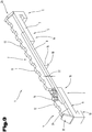
- a preferred embodiment of a climbing aid 1 is shown.
- the climbing aid 1 which can also be referred to as an anti-skid device, is provided for a caterpillar chain, not shown, of a machine, such as an excavator or a snowcat.
- Crawler chains of this type have chain links articulated to one another via hinge pins and chain plates screwed onto these chain links.
- the chain plates On an upper side that comes into contact with the floor on which the machine stands, the chain plates have a profiling with elevations, for example with protruding webs running transversely to the longitudinal direction of the chain.
- the profiling can, however, also be designed differently, but with the restriction that the profiling does not interfere with the assembly of the climbing aid on the crawler chain.
- the caterpillar chain may not have a sufficient grip on soggy or frozen ground.
- the climbing aid 1 can be mounted on the caterpillar chain.
- the climbing aid 1 is arranged between two elevations, for example between two directly adjacent webs running transversely to the direction of travel, of the profiling.
- the climbing aid 1 comprises or consists of a base body which is formed from profile elements 3, 4 connected to one another at an overlap joint 2.
- profile elements 3, 4 can also be provided, for example three or four, so that more than one lap joint 2 can also be formed.
- the design with only two profile elements 3, 4 is preferred.
- the first profile element 3 has a first carrier profile 5 and the second profile element 4 has a second carrier profile 6.
- the first carrier profile 5 is designed in two parts in the embodiment variant shown, and has a second carrier profile part 8 on a first carrier profile part 7, which is connected to the first carrier profile part 7, in particular is connected in a materially bonded manner, preferably by welding.
- the second carrier profile 5 is preferably made in one piece, but can also have several parts.
- the two carrier profiles 5, 6 have holding elements 9, 10, which are preferably formed in one piece with the carrier profiles 5, 6. These holding elements 9, 10 are in particular U-shaped, so that the two carrier profiles 5, 6 can be arranged to encompass the side areas of the respective chain plate on which the climbing aid 1 is arranged.
- the two support profiles 5, 6 are preferably made from flat steel by appropriate forming, but can at least partially also by another method, e.g. a casting process.
- a first climbing aid profile element 11 is arranged on the first carrier profile 5 and a second climbing aid profile element 12 is arranged on the second carrier profile 6.
- the two climbing aid profile elements 11, 12 are connected to the respective carrier profile 5, 6, in particular connected in a materially bonded manner, preferably welded.
- the two climbing aid profile elements 11, 12 are arranged rotated by 90 ° on the respective carrier profile 5, 6, that is, they rest with a side face on the carrier profiles 5, 6, as shown in FIGS Figures 1 to 3 can be seen.
- the two climbing aid profile elements 11, 12 are in particular also made from a flat material by machining, and can also be made using another method, e.g. a casting process. They each have a profile with elevations 13 and protrude beyond the carrier profiles 5, 6 in the vertical direction. With the help of this profiling, which also protrudes above the profiling of the chain plates in the vertical direction, the caterpillar chain has a better hold during operation, as it can dig further into the ground.
- climbing aid 1 is usually mounted on the caterpillar chain. Since all climbing aids are preferably designed the same, only one climbing aid 1 is described in this description. These explanations can also be applied to the other climbing aids 1 of the caterpillar chain.
- the two profile elements 3, 4 are connected to one another. They are preferably screwed together by means of screws 14.
- two screws 14 are provided. These are preferably arranged offset from one another diagonally, as shown in FIGS Fig. 2 and 3 can be seen. A higher security of the screw connection can thus be achieved.
- the screw connection can be carried out by means of nuts or by means of threads in the profile element 4 arranged below.
- the two profile elements 3, 4 are preferably screwed together off-center (based on a longitudinal extension 15 of the climbing aid 1). But it can also be carried out in the middle.
- At least one support profile 16 is arranged on the underside of the first carrier profile 5 and connected to the first carrier profile 5, via which the climbing aid 1 can additionally support itself on the upper side of the chain plate of the caterpillar chain. In the case of only one support profile 16, this is arranged at least approximately in the middle (in relation to the longitudinal extension 16) on the climbing aid 1.
- two or three or more support profiles 16 can also be provided.
- a height 17 of the at least one support profile 16 depends on the material thickness of the carrier profiles 5, 6.
- An end face 18 of the at least one support profile 16 is at least approximately aligned with an underside 19 (next to the U-shaped holding elements 9, 10) of the carrier profiles 5 , 6 arranged.
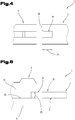
- a recess 21 is provided in an end face 21, as shown in FIG Fig. 4
- the illustrated plan view of a section from the climbing aid 1 shows.
- the recess 21 is formed exclusively in the first profile part 3.
- the recess 21 can also be formed exclusively in the second profile part 4.
- the two profile parts 3, 4 are pushed into one another in the region of the recess 21 to form the form fit, as shown, for example, in FIG Fig. 3 can be seen.
- the recess 21 extends in the variant of the climbing aid 1 to Fig. 4 through a total thickness of 22 ( Fig. 3 ) of the support profile 3 in the area of the form fit (viewed in the vertical direction).
- the recess 21 also extends in the direction of the longitudinal extension 15 ( Fig. 2 ) of the climbing aid 1 starting at the end face 20 of the first profile part 3 over a depth 23.
- the size of the depth 23 can be adapted to the respective requirements of the climbing aid 1 and, for example, between 2% and 10% of the total length of the climbing aid 1 in the direction of the longitudinal extension 15.
- the shape of the recess 21 is based on the shape of the second profile part 4 in the area in which it is pushed into the recess 21.
- the recess can have a rectangular shape - viewed in plan view.
- both profile elements 3, 4 forming the form fit each have a recess 21 on the end face, as shown in FIG Fig. 5 is shown, which shows a detail from a further embodiment of the climbing aid 1 in side view.
- the above statements apply to both recesses 21, but the (total) depth 23 ( Fig. 4 ) the recess 21 is now divided into two recesses 21.
- the division can be selected, for example, from a range from 60:40 to 40:60, and for example 50:50.
- the numbers are in% based on the total depth of the recesses in the horizontal direction.
- the form fit between the two profile parts 3, 4 can be formed via the at least one recess 21 at any suitable point on the end face.
- the recess 21 can be formed in the carrier profile 6 of the second profile part 4.
- the carrier profile 5 of the first profile part 3 can have a vertically downwardly protruding web which engages in the recess 21 of the carrier profile 6 of the second profile part 3 to form the form fit.
- a recess 21 of the form-fitting connection is formed in one of the carrier profiles 5, 6 and the further recess 21 is formed in one of the climbing aid profile elements 11, 12.
- the illustrated embodiment of the climbing aid 1 is a recess 21 in the support profile 5 of the first profile part 3 and the second recess 21 in the climbing aid profile element 12 of the second profile part 4.
- the recess 21 in the climbing aid profile element 12 extends from the contact surface 24 (also from Fig. 3 visible) on the carrier profile 6 of the second profile element 4 over a vertical height 25 which corresponds at least approximately to the thickness 22 of the carrier profile 5 of the first profile element 3 in this area.
- the height 25 is dimensioned such that the two profile elements 3, 4 can be pushed into one another and at the same time the form fit between the profile elements 3, 4 is formed.
- the height 25 will therefore only be slightly greater than the thickness 22.
- the profile elements 3, 4 in the lap joint 2 lie flat against one another.
- the surfaces forming the lap joint 2 and / or the surfaces forming the form fit the profile elements 3, 4 are provided with a friction-increasing coating.
- This coating can, for example, be based on synthetic resin, for example a lacquer. Hard particles, such as corundum particles or diamond particles, etc. can be used in the coating to increase friction.
- At least one elongated hole can be provided in one of the profile elements 3, 4, as shown in FIG DE 20 2012 100 868 U1 is described.
- the two U-shaped retaining elements 9, 10 are first pushed from opposite sides onto the side edges of the chain plates between two adjacent elevations of the profile of the chain plates and then the two profile elements 3, 4 are pushed into one another to form the form fit.
- the two profile elements 3, 4 are then screwed together with at least one screw 14 in the formed overlap joint.
- ice claws can be provided for particularly harsh winter conditions. These ice claws can, for example, be plate-shaped, and at their front end they can be formed with elevations similar to the elevations 13 of the climbing aid profile elements 11, 12. The ice claws can be arranged at least orthogonally to the climbing aid profile elements 11, 12 on the climbing aid profile elements 11, 12.
- plate-shaped protective elements 26 in the side regions of the climbing aid and with the climbing aid profile elements 11, 12 and / or the carrier profiles 5, 6 to connect like this for example Fig. 3 can be seen.
- These protective elements 26 can, for example, be trapezoidal.
- the described separable form-fitting connection of the two profile elements 3, 4 with one another in a form-fitting manner can additionally also be designed in a force-fitting manner.
- the exemplary embodiments show or describe possible design variants of the climbing aid 1, it being noted at this point that combinations of the individual design variants with one another are also possible.
Landscapes
- Engineering & Computer Science (AREA)
- Chemical & Material Sciences (AREA)
- Combustion & Propulsion (AREA)
- Transportation (AREA)
- Mechanical Engineering (AREA)
- Joining Of Building Structures In Genera (AREA)
- Road Paving Structures (AREA)
Claims (6)
- Aide à la montée (1) pour une machine avec une chenille, comprenant un corps de base qui est constitué d'éléments profilés (3, 4) reliés entre eux au niveau d'un joint à recouvrement (2), dans laquelle les éléments profilés (3, 4) comprennent un profilé porteur (5, 6) sur lequel est disposé un élément profilé d'aide à la montée (11, 12), qui dépasse du profilé porteur (5, 6) et dans lequel les éléments profilés (3, 4) du corps de base sont reliés entre eux par complémentarité de forme au niveau du joint à recouvrement (2), caractérisé en ce que, pour la formation de la liaison par complémentarité de forme des éléments profilés (3, 4), au moins un de ces éléments profilés (3, 4) comprend, face frontale, un évidement (21) et les éléments profilés (3, 4) sont insérés les uns dans les autres au niveau de cet évidement (21).
- Aide à la montée (1) selon la revendication 1, caractérisée en ce que les deux éléments profilés (3, 4) formant la complémentarité de forme comprennent, sur leur face frontale, un évidement (21).
- Aide à la montée (1) selon la revendication 2, caractérisée en ce qu'un évidement (21) de la liaison par complémentarité de forme est réalisée dans un des profilés porteurs (5, 6) et l'autre évidement (21) est réalisé dans un des éléments profilés de l'aide à la montée (11, 12).
- Aide à la montée (1) selon la revendication 1 ou 2, caractérisée en ce que les éléments profilés (3, 4) s'appuient les uns contre les autres de manière plane dans le joint à recouvrement (2).
- Aide à la montée (1) selon l'une des revendications 1 à 3, caractérisée en ce que les surfaces formant le joint à recouvrement (2) et/ou les surfaces formant la complémentarité de forme, des éléments profilés (3, 4) sont munies d'un revêtement augmentant la friction.
- Chenille pour une machine, avec des patins qui présentent un côté supérieur, dans lequel le côté supérieur comprend un profilage avec des bossages, ainsi qu'avec au moins une aide à la montée (1) qui est disposée entre deux bossages du profilage du côté supérieur des patins, et des éléments de maintien en forme de U (9, 10) pour la disposition de l'aide à la montée (1) sur la chenille, qui entourent les bords latéraux des patins, caractérisée en ce que l'aide à la montée (1) est réalisée selon l'une des revendications précédentes.
Applications Claiming Priority (1)
| Application Number | Priority Date | Filing Date | Title |
|---|---|---|---|
| ATA50237/2018A AT520750B1 (de) | 2018-03-21 | 2018-03-21 | Steighilfe |
Publications (2)
| Publication Number | Publication Date |
|---|---|
| EP3552931A1 EP3552931A1 (fr) | 2019-10-16 |
| EP3552931B1 true EP3552931B1 (fr) | 2020-09-23 |
Family
ID=65724248
Family Applications (1)
| Application Number | Title | Priority Date | Filing Date |
|---|---|---|---|
| EP19161269.6A Active EP3552931B1 (fr) | 2018-03-21 | 2019-03-07 | Aide à la montée |
Country Status (2)
| Country | Link |
|---|---|
| EP (1) | EP3552931B1 (fr) |
| AT (1) | AT520750B1 (fr) |
Families Citing this family (3)
| Publication number | Priority date | Publication date | Assignee | Title |
|---|---|---|---|---|
| US11390341B2 (en) * | 2015-12-24 | 2022-07-19 | Jb Innovations Limited | Device to enhance the traction of a tracked vehicle |
| WO2022130419A1 (fr) * | 2020-12-17 | 2022-06-23 | Esto Srl | Dispositif antidérapant pour équiper une chaîne à chenilles |
| AT525915B1 (de) | 2022-09-05 | 2023-09-15 | Christoph Hettegger Ing Rupert | Traktionshilfe |
Family Cites Families (4)
| Publication number | Priority date | Publication date | Assignee | Title |
|---|---|---|---|---|
| US2701169A (en) * | 1954-08-18 | 1955-02-01 | Edgar M Cannon | Mud lug for endless traction track links |
| US7901015B1 (en) * | 2007-03-23 | 2011-03-08 | Deloren E. Anderson | Traction cleats for tracked construction equipment |
| AT12423U1 (de) * | 2011-04-14 | 2012-05-15 | Hettegger Rupert | Gleitschutzvorrichtung für eine raupenkette |
| CN205574091U (zh) * | 2016-03-17 | 2016-09-14 | 浙江永鼎机械科技股份有限公司 | 一种橡胶履带及其防滑齿 |
-
2018
- 2018-03-21 AT ATA50237/2018A patent/AT520750B1/de not_active IP Right Cessation
-
2019
- 2019-03-07 EP EP19161269.6A patent/EP3552931B1/fr active Active
Non-Patent Citations (1)
| Title |
|---|
| None * |
Also Published As
| Publication number | Publication date |
|---|---|
| AT520750A4 (de) | 2019-07-15 |
| EP3552931A1 (fr) | 2019-10-16 |
| AT520750B1 (de) | 2019-07-15 |
Similar Documents
| Publication | Publication Date | Title |
|---|---|---|
| EP2069577B1 (fr) | Système de retenue de véhicules | |
| EP0544236B1 (fr) | Profil de bande de roulement pour pneumatique | |
| EP3552931B1 (fr) | Aide à la montée | |
| DE69711701T2 (de) | Mittelstreifenleitplanken | |
| EP2205797B1 (fr) | Système de retenue pour véhicules | |
| EP3708473A1 (fr) | Aide à l'escalade | |
| EP0049323A1 (fr) | Revêtement de sol pour voies de roulement | |
| EP2712962B2 (fr) | Dispositif destiné à relier deux éléments de paroi de protection mobiles | |
| DE69515426T2 (de) | Versetzbahres Fahrbahnbegrenzungselement, Fahrbahnbegrenzung damit hergestellt und Verfahren zur Herstellung | |
| AT524130B1 (de) | Steighilfe | |
| DE2540267A1 (de) | Aus scheiben zusammengesetztes tragwerk, insbesondere fuer eine zerlegbare bruecke | |
| WO2012059096A1 (fr) | Pont modulaire et procédé de construction d'un pont modulaire | |
| DE202006004364U1 (de) | Schutzplankenstrang | |
| DE3624109C1 (de) | Triebstockstange fuer den Vorschub eines im Untertageeinsatz befindlichen Walzenladers | |
| DE102008026661B4 (de) | Verkehrsleitwand | |
| DE102012223844A1 (de) | Temporäre hilfsbrücken-abstützeinrichtung für gleisabschnitte | |
| DE1658492C3 (de) | Befestigung aus Betongitterplatten, insbesondere für Fahrbahnen | |
| EP2333160A1 (fr) | Dispositif de guidage de la circulation | |
| DE102009028904A1 (de) | Leitplanke oder Schutzplanke, bestehend aus einem einzigen Element oder aus mehreren in Längsrichtung aneinandergekoppelten Elementen | |
| EP0583684B1 (fr) | Plaque de support pour ponts et rampes | |
| AT525915B1 (de) | Traktionshilfe | |
| DE19503429B4 (de) | Vorrichtung für das stirnseitige Verbinden von Kabelbahnen | |
| EP3299519B1 (fr) | Élément de pontage d'un pont déplaçable et élément de contact au sol pour un élément de pontage | |
| DE102018104706A1 (de) | Auffahrschiene | |
| DE102023129392A1 (de) | Auffahrschiene |
Legal Events
| Date | Code | Title | Description |
|---|---|---|---|
| PUAI | Public reference made under article 153(3) epc to a published international application that has entered the european phase |
Free format text: ORIGINAL CODE: 0009012 |
|
| STAA | Information on the status of an ep patent application or granted ep patent |
Free format text: STATUS: THE APPLICATION HAS BEEN PUBLISHED |
|
| AK | Designated contracting states |
Kind code of ref document: A1 Designated state(s): AL AT BE BG CH CY CZ DE DK EE ES FI FR GB GR HR HU IE IS IT LI LT LU LV MC MK MT NL NO PL PT RO RS SE SI SK SM TR |
|
| AX | Request for extension of the european patent |
Extension state: BA ME |
|
| STAA | Information on the status of an ep patent application or granted ep patent |
Free format text: STATUS: REQUEST FOR EXAMINATION WAS MADE |
|
| 17P | Request for examination filed |
Effective date: 20191121 |
|
| RAX | Requested extension states of the european patent have changed |
Extension state: BA Payment date: 20191121 Extension state: ME Payment date: 20191121 |
|
| RBV | Designated contracting states (corrected) |
Designated state(s): AL AT BE BG CH CY CZ DE DK EE ES FI FR GB GR HR HU IE IS IT LI LT LU LV MC MK MT NL NO PL PT RO RS SE SI SK SM TR |
|
| RIC1 | Information provided on ipc code assigned before grant |
Ipc: B62D 55/28 20060101AFI20200305BHEP |
|
| GRAP | Despatch of communication of intention to grant a patent |
Free format text: ORIGINAL CODE: EPIDOSNIGR1 |
|
| STAA | Information on the status of an ep patent application or granted ep patent |
Free format text: STATUS: GRANT OF PATENT IS INTENDED |
|
| INTG | Intention to grant announced |
Effective date: 20200512 |
|
| GRAJ | Information related to disapproval of communication of intention to grant by the applicant or resumption of examination proceedings by the epo deleted |
Free format text: ORIGINAL CODE: EPIDOSDIGR1 |
|
| GRAP | Despatch of communication of intention to grant a patent |
Free format text: ORIGINAL CODE: EPIDOSNIGR1 |
|
| GRAJ | Information related to disapproval of communication of intention to grant by the applicant or resumption of examination proceedings by the epo deleted |
Free format text: ORIGINAL CODE: EPIDOSDIGR1 |
|
| STAA | Information on the status of an ep patent application or granted ep patent |
Free format text: STATUS: REQUEST FOR EXAMINATION WAS MADE |
|
| INTG | Intention to grant announced |
Effective date: 20200626 |
|
| GRAP | Despatch of communication of intention to grant a patent |
Free format text: ORIGINAL CODE: EPIDOSNIGR1 |
|
| INTC | Intention to grant announced (deleted) | ||
| STAA | Information on the status of an ep patent application or granted ep patent |
Free format text: STATUS: GRANT OF PATENT IS INTENDED |
|
| GRAS | Grant fee paid |
Free format text: ORIGINAL CODE: EPIDOSNIGR3 |
|
| GRAA | (expected) grant |
Free format text: ORIGINAL CODE: 0009210 |
|
| STAA | Information on the status of an ep patent application or granted ep patent |
Free format text: STATUS: THE PATENT HAS BEEN GRANTED |
|
| INTG | Intention to grant announced |
Effective date: 20200806 |
|
| AK | Designated contracting states |
Kind code of ref document: B1 Designated state(s): AL AT BE BG CH CY CZ DE DK EE ES FI FR GB GR HR HU IE IS IT LI LT LU LV MC MK MT NL NO PL PT RO RS SE SI SK SM TR |
|
| AX | Request for extension of the european patent |
Extension state: BA ME |
|
| REG | Reference to a national code |
Ref country code: GB Ref legal event code: FG4D Free format text: NOT ENGLISH |
|
| REG | Reference to a national code |
Ref country code: CH Ref legal event code: EP |
|
| REG | Reference to a national code |
Ref country code: IE Ref legal event code: FG4D Free format text: LANGUAGE OF EP DOCUMENT: GERMAN |
|
| REG | Reference to a national code |
Ref country code: DE Ref legal event code: R096 Ref document number: 502019000244 Country of ref document: DE Ref country code: AT Ref legal event code: REF Ref document number: 1316129 Country of ref document: AT Kind code of ref document: T Effective date: 20201015 |
|
| REG | Reference to a national code |
Ref country code: CH Ref legal event code: NV Representative=s name: ABP PATENT NETWORK AG, CH |
|
| REG | Reference to a national code |
Ref country code: SE Ref legal event code: TRGR |
|
| PG25 | Lapsed in a contracting state [announced via postgrant information from national office to epo] |
Ref country code: HR Free format text: LAPSE BECAUSE OF FAILURE TO SUBMIT A TRANSLATION OF THE DESCRIPTION OR TO PAY THE FEE WITHIN THE PRESCRIBED TIME-LIMIT Effective date: 20200923 Ref country code: BG Free format text: LAPSE BECAUSE OF FAILURE TO SUBMIT A TRANSLATION OF THE DESCRIPTION OR TO PAY THE FEE WITHIN THE PRESCRIBED TIME-LIMIT Effective date: 20201223 Ref country code: GR Free format text: LAPSE BECAUSE OF FAILURE TO SUBMIT A TRANSLATION OF THE DESCRIPTION OR TO PAY THE FEE WITHIN THE PRESCRIBED TIME-LIMIT Effective date: 20201224 Ref country code: FI Free format text: LAPSE BECAUSE OF FAILURE TO SUBMIT A TRANSLATION OF THE DESCRIPTION OR TO PAY THE FEE WITHIN THE PRESCRIBED TIME-LIMIT Effective date: 20200923 |
|
| PG25 | Lapsed in a contracting state [announced via postgrant information from national office to epo] |
Ref country code: LV Free format text: LAPSE BECAUSE OF FAILURE TO SUBMIT A TRANSLATION OF THE DESCRIPTION OR TO PAY THE FEE WITHIN THE PRESCRIBED TIME-LIMIT Effective date: 20200923 Ref country code: RS Free format text: LAPSE BECAUSE OF FAILURE TO SUBMIT A TRANSLATION OF THE DESCRIPTION OR TO PAY THE FEE WITHIN THE PRESCRIBED TIME-LIMIT Effective date: 20200923 |
|
| REG | Reference to a national code |
Ref country code: NO Ref legal event code: T2 Effective date: 20200923 |
|
| REG | Reference to a national code |
Ref country code: NL Ref legal event code: MP Effective date: 20200923 |
|
| REG | Reference to a national code |
Ref country code: LT Ref legal event code: MG4D |
|
| PG25 | Lapsed in a contracting state [announced via postgrant information from national office to epo] |
Ref country code: SM Free format text: LAPSE BECAUSE OF FAILURE TO SUBMIT A TRANSLATION OF THE DESCRIPTION OR TO PAY THE FEE WITHIN THE PRESCRIBED TIME-LIMIT Effective date: 20200923 Ref country code: LT Free format text: LAPSE BECAUSE OF FAILURE TO SUBMIT A TRANSLATION OF THE DESCRIPTION OR TO PAY THE FEE WITHIN THE PRESCRIBED TIME-LIMIT Effective date: 20200923 Ref country code: CZ Free format text: LAPSE BECAUSE OF FAILURE TO SUBMIT A TRANSLATION OF THE DESCRIPTION OR TO PAY THE FEE WITHIN THE PRESCRIBED TIME-LIMIT Effective date: 20200923 Ref country code: RO Free format text: LAPSE BECAUSE OF FAILURE TO SUBMIT A TRANSLATION OF THE DESCRIPTION OR TO PAY THE FEE WITHIN THE PRESCRIBED TIME-LIMIT Effective date: 20200923 Ref country code: PT Free format text: LAPSE BECAUSE OF FAILURE TO SUBMIT A TRANSLATION OF THE DESCRIPTION OR TO PAY THE FEE WITHIN THE PRESCRIBED TIME-LIMIT Effective date: 20210125 Ref country code: EE Free format text: LAPSE BECAUSE OF FAILURE TO SUBMIT A TRANSLATION OF THE DESCRIPTION OR TO PAY THE FEE WITHIN THE PRESCRIBED TIME-LIMIT Effective date: 20200923 |
|
| PG25 | Lapsed in a contracting state [announced via postgrant information from national office to epo] |
Ref country code: AL Free format text: LAPSE BECAUSE OF FAILURE TO SUBMIT A TRANSLATION OF THE DESCRIPTION OR TO PAY THE FEE WITHIN THE PRESCRIBED TIME-LIMIT Effective date: 20200923 Ref country code: ES Free format text: LAPSE BECAUSE OF FAILURE TO SUBMIT A TRANSLATION OF THE DESCRIPTION OR TO PAY THE FEE WITHIN THE PRESCRIBED TIME-LIMIT Effective date: 20200923 Ref country code: PL Free format text: LAPSE BECAUSE OF FAILURE TO SUBMIT A TRANSLATION OF THE DESCRIPTION OR TO PAY THE FEE WITHIN THE PRESCRIBED TIME-LIMIT Effective date: 20200923 Ref country code: IS Free format text: LAPSE BECAUSE OF FAILURE TO SUBMIT A TRANSLATION OF THE DESCRIPTION OR TO PAY THE FEE WITHIN THE PRESCRIBED TIME-LIMIT Effective date: 20210123 |
|
| REG | Reference to a national code |
Ref country code: DE Ref legal event code: R097 Ref document number: 502019000244 Country of ref document: DE |
|
| PG25 | Lapsed in a contracting state [announced via postgrant information from national office to epo] |
Ref country code: SK Free format text: LAPSE BECAUSE OF FAILURE TO SUBMIT A TRANSLATION OF THE DESCRIPTION OR TO PAY THE FEE WITHIN THE PRESCRIBED TIME-LIMIT Effective date: 20200923 |
|
| PLBE | No opposition filed within time limit |
Free format text: ORIGINAL CODE: 0009261 |
|
| STAA | Information on the status of an ep patent application or granted ep patent |
Free format text: STATUS: NO OPPOSITION FILED WITHIN TIME LIMIT |
|
| PG25 | Lapsed in a contracting state [announced via postgrant information from national office to epo] |
Ref country code: DK Free format text: LAPSE BECAUSE OF FAILURE TO SUBMIT A TRANSLATION OF THE DESCRIPTION OR TO PAY THE FEE WITHIN THE PRESCRIBED TIME-LIMIT Effective date: 20200923 Ref country code: SI Free format text: LAPSE BECAUSE OF FAILURE TO SUBMIT A TRANSLATION OF THE DESCRIPTION OR TO PAY THE FEE WITHIN THE PRESCRIBED TIME-LIMIT Effective date: 20200923 |
|
| 26N | No opposition filed |
Effective date: 20210624 |
|
| PG25 | Lapsed in a contracting state [announced via postgrant information from national office to epo] |
Ref country code: MC Free format text: LAPSE BECAUSE OF FAILURE TO SUBMIT A TRANSLATION OF THE DESCRIPTION OR TO PAY THE FEE WITHIN THE PRESCRIBED TIME-LIMIT Effective date: 20200923 |
|
| REG | Reference to a national code |
Ref country code: BE Ref legal event code: MM Effective date: 20210331 |
|
| PG25 | Lapsed in a contracting state [announced via postgrant information from national office to epo] |
Ref country code: LU Free format text: LAPSE BECAUSE OF NON-PAYMENT OF DUE FEES Effective date: 20210307 Ref country code: IE Free format text: LAPSE BECAUSE OF NON-PAYMENT OF DUE FEES Effective date: 20210307 |
|
| PG25 | Lapsed in a contracting state [announced via postgrant information from national office to epo] |
Ref country code: BE Free format text: LAPSE BECAUSE OF NON-PAYMENT OF DUE FEES Effective date: 20210331 |
|
| PG25 | Lapsed in a contracting state [announced via postgrant information from national office to epo] |
Ref country code: NL Free format text: LAPSE BECAUSE OF NON-PAYMENT OF DUE FEES Effective date: 20200923 Ref country code: CY Free format text: LAPSE BECAUSE OF FAILURE TO SUBMIT A TRANSLATION OF THE DESCRIPTION OR TO PAY THE FEE WITHIN THE PRESCRIBED TIME-LIMIT Effective date: 20200923 |
|
| P01 | Opt-out of the competence of the unified patent court (upc) registered |
Effective date: 20230601 |
|
| PG25 | Lapsed in a contracting state [announced via postgrant information from national office to epo] |
Ref country code: HU Free format text: LAPSE BECAUSE OF FAILURE TO SUBMIT A TRANSLATION OF THE DESCRIPTION OR TO PAY THE FEE WITHIN THE PRESCRIBED TIME-LIMIT; INVALID AB INITIO Effective date: 20190307 |
|
| GBPC | Gb: european patent ceased through non-payment of renewal fee |
Effective date: 20230307 |
|
| PG25 | Lapsed in a contracting state [announced via postgrant information from national office to epo] |
Ref country code: GB Free format text: LAPSE BECAUSE OF NON-PAYMENT OF DUE FEES Effective date: 20230307 |
|
| PG25 | Lapsed in a contracting state [announced via postgrant information from national office to epo] |
Ref country code: GB Free format text: LAPSE BECAUSE OF NON-PAYMENT OF DUE FEES Effective date: 20230307 |
|
| PG25 | Lapsed in a contracting state [announced via postgrant information from national office to epo] |
Ref country code: MK Free format text: LAPSE BECAUSE OF FAILURE TO SUBMIT A TRANSLATION OF THE DESCRIPTION OR TO PAY THE FEE WITHIN THE PRESCRIBED TIME-LIMIT Effective date: 20200923 |
|
| PG25 | Lapsed in a contracting state [announced via postgrant information from national office to epo] |
Ref country code: TR Free format text: LAPSE BECAUSE OF FAILURE TO SUBMIT A TRANSLATION OF THE DESCRIPTION OR TO PAY THE FEE WITHIN THE PRESCRIBED TIME-LIMIT Effective date: 20200923 |
|
| PG25 | Lapsed in a contracting state [announced via postgrant information from national office to epo] |
Ref country code: MT Free format text: LAPSE BECAUSE OF FAILURE TO SUBMIT A TRANSLATION OF THE DESCRIPTION OR TO PAY THE FEE WITHIN THE PRESCRIBED TIME-LIMIT Effective date: 20200923 |
|
| PGFP | Annual fee paid to national office [announced via postgrant information from national office to epo] |
Ref country code: IT Payment date: 20250306 Year of fee payment: 7 |
|
| PGFP | Annual fee paid to national office [announced via postgrant information from national office to epo] |
Ref country code: CH Payment date: 20250429 Year of fee payment: 7 |
|
| PGFP | Annual fee paid to national office [announced via postgrant information from national office to epo] |
Ref country code: SE Payment date: 20260323 Year of fee payment: 8 |
|
| PGFP | Annual fee paid to national office [announced via postgrant information from national office to epo] |
Ref country code: NO Payment date: 20260325 Year of fee payment: 8 Ref country code: DE Payment date: 20260320 Year of fee payment: 8 |
|
| PGFP | Annual fee paid to national office [announced via postgrant information from national office to epo] |
Ref country code: AT Payment date: 20260302 Year of fee payment: 8 |
|
| PGFP | Annual fee paid to national office [announced via postgrant information from national office to epo] |
Ref country code: FR Payment date: 20260327 Year of fee payment: 8 |