EP3552932A1 - Entraînement auxiliaire pour un véhicule, en particulier pour une remorque, ainsi que remorque - Google Patents
Entraînement auxiliaire pour un véhicule, en particulier pour une remorque, ainsi que remorque Download PDFInfo
- Publication number
- EP3552932A1 EP3552932A1 EP19167634.5A EP19167634A EP3552932A1 EP 3552932 A1 EP3552932 A1 EP 3552932A1 EP 19167634 A EP19167634 A EP 19167634A EP 3552932 A1 EP3552932 A1 EP 3552932A1
- Authority
- EP
- European Patent Office
- Prior art keywords
- drive roller
- drive
- housing
- wheel
- auxiliary drive
- Prior art date
- Legal status (The legal status is an assumption and is not a legal conclusion. Google has not performed a legal analysis and makes no representation as to the accuracy of the status listed.)
- Granted
Links
Images


Classifications
-
- B—PERFORMING OPERATIONS; TRANSPORTING
- B62—LAND VEHICLES FOR TRAVELLING OTHERWISE THAN ON RAILS
- B62D—MOTOR VEHICLES; TRAILERS
- B62D59/00—Trailers with driven ground wheels or the like
- B62D59/04—Trailers with driven ground wheels or the like driven from propulsion unit on trailer
Definitions
- the present invention relates to an auxiliary drive for a vehicle, in particular for a trailer such as a caravan, a boat trailer, a sales car, a transport trailer or a car transport trailer, according to the preamble of claim 1. Furthermore, the invention relates to a trailer with such an auxiliary drive.
- auxiliary drive has an engine designed, for example, as an electric motor and a drive drivable by the engine. This means that torques provided by the engine can be introduced into the transmission.
- the auxiliary drive has a housing in which at least the transmission is accommodated.
- the auxiliary drive comprises at least one drive roller, which can be driven by the motor via the gearbox and thereby rotatable relative to the housing, which is also referred to as a drive roller.
- the drive roller may be moved in support, that is, in contact with at least one wheel of the vehicle, so that when the drive roller is driven by the engine via the transmission while the drive roller is in support with the wheel, the wheel is over the drive roller and can be driven by the engine via the transmission, respectively is driven.
- the motorless vehicle can be moved in a particularly simple manner and in particular be ranked.
- Object of the present invention is to develop an auxiliary drive and a trailer of the type mentioned in such a way that a particularly advantageous arrangement of the auxiliary drive can be realized on the vehicle.
- the inventive also known as Rangierantrieb or maneuvering auxiliary drive for a vehicle, in particular for a trailer such as a caravan, a boat trailer, a sales car, a trailer, a car transport trailer or a caravan has a motor, which is preferably designed as an electric motor.
- the engine designed as an electric motor has a stator and a rotor, which is drivable by the stator and thereby rotatable about a motor axis relative to the stator.
- the auxiliary drive on a transmission which is driven by the motor. This means that from the engine, in particular via the rotor, provided or provided torques are introduced or can be introduced into the transmission, whereby the transmission is driven.
- the auxiliary drive comprises a housing in which at least the gear is at least partially, in particular at least predominantly or completely, added.
- the auxiliary drive further comprises at least one drive roller, also referred to as a drive roller, which is rotatable via the transmission of the motor, in particular of the rotor, and thereby relative to the housing.
- the drive roller is drivable via the gearbox of the motor and thereby rotatable about an axis of rotation relative to the housing.
- the axis of rotation of the drive roller coincides with its axial direction.
- the drive roller with the transmission and, for example via the transmission with the engine, in particular with the rotor, in particular permanently coupled.
- the respective, from the engine, in particular via the rotor, provided torque can in the Transmission are transmitted and transmitted via the transmission to the drive roller, whereby the drive roller can be driven and thereby rotated about its axis of rotation relative to the housing.
- the transmission is designed, for example, to convert the torque provided by the engine into a different starting torque, by means of which the drive roller can be driven and thereby rotatable about the axis of rotation relative to the housing.
- the drive roller is in the radial direction of the drive roller in support system and thus in contact with at least one wheel of the vehicle, in particular with a tire of the wheel of the vehicle, movable, so driven by driving the drive roller, the wheel on the drive roller and the transmission of the engine can be.
- the drive roller is driven by the motor via the gearbox and thereby rotated about the axis of rotation relative to the housing while the drive roller is in support and thus in contact with the wheel, the wheel is driven and thereby, for example, relative to a structure of the vehicle turned.
- the vehicle can be moved and parked in a particularly simple and precise manner by means of the motor and thus motor-driven and parked, so that the motorless vehicle, for example, does not have to be maneuvered manually or by muscle power.
- the vehicle is preferably designed motorless or unpowered, so that the vehicle can not drive independently or not with their own power.
- the auxiliary drive is a component which is external to the vehicle and is provided in addition to the vehicle, which component, in particular reversibly detachable, can be fastened to the vehicle.
- the feature that the auxiliary drive is preferably a component which is external to the vehicle and is provided in addition to the vehicle is to be understood in particular as meaning that the auxiliary drive is not a component and thus not part of the vehicle.
- the auxiliary drive particularly advantageous to the vehicle and thereby to be able to position particularly advantageous and flexible relative to the vehicle, it is inventively provided that at least part of the outer peripheral side surface forming the maximum outer diameter of the drive roller the drive roller, the housing in the radial direction of the drive roller by at least 10 millimeters, that projects beyond at least one centimeter.
- the drive roller has the outer peripheral side surface which can be moved in the manner described in the radial direction of the drive roller in support system and thus in contact with the wheel.
- the drive roller is the drive roller along its radial direction in support system with the wheel, so the drive roller is on its outer peripheral side surface in support system with the wheel, so that the outer peripheral side surface of the drive roller touches the wheel.
- the housing does not protrude in the radial direction of the drive roller at least over said part of the outer peripheral side surface, the auxiliary drive and thus the drive roller in the axial direction of the drive roller can be arranged and aligned particularly advantageous and in particular flexible relative to the wheel and thus relative to the vehicle become.
- the distance or overhang between at least the part and the housing is not less than 10 millimeters, wherein preferably the part extends over the entire axial extent of the drive roller.
- the housing is preferably the furthest projecting housing or the outermost housing of the auxiliary drive.
- the Auxiliary drive for example, have a plurality of housings arranged one inside the other, in which the gear can be arranged at least partially.
- the housing which is surmounted at least by the part in the manner described, is the outermost housing of the auxiliary drive, wherein the transmission is at least partially, in particular at least predominantly or completely, disposed in the outermost housing.
- the housing forms at least one subregion of a person who is visually and haptically perceptible by the person staying in the surroundings of the auxiliary drive.
- the transmission is at least partially disposed in the outermost housing, is to be understood in particular that the transmission to the outside, that is, in the direction of the environment of the auxiliary drive, at least partially covered by the outermost housing.
- the transmission may also be at least partially received in an inner housing, which may be at least partially received in the outermost housing.
- the drive roller can be moved in a translatory manner in a support system with the wheel in a support direction coinciding with the radial direction of the drive roller.
- the auxiliary drive in a particularly flexible manner relative to the vehicle, it is provided that at least the part of the outer peripheral side jacket surface projects beyond the housing in the supporting direction.
- the invention is based in particular on the following finding: In conventional, also known as maneuvering auxiliary drives especially for caravans and other towed vehicles usually also referred to as gear housing housing, especially in the last drive gear of the gearbox, extends beyond the maximum outer diameter of the wheel driving drive roller in the radial direction of the drive roller addition.
- the drive roller can not be freely arranged in its axial direction relative to the wheel and in particular on its running surface, since otherwise the housing in Contact with the wheel comes and / or the housing prevents the drive roller can be moved in its radial direction in support system with the wheel. Consequently, the housing usually extends at least on one side, that is to say on at least one axial side of the drive roller beyond its maximum outer diameter in the radial direction of the drive roller. In addition, the housing may extend beyond the maximum lateral extent of the wheel, in particular its tire, at least on one side. This can lead to collisions with other attachments of the vehicle such as a shock absorber, chassis or frame parts, a fender, wheel arches and / or a skirt. In some cases, assembly of the auxiliary drive on the vehicle is thus not possible at all. When mounting the auxiliary drive with outwardly facing housing, this can protrude outward over the wheel or its tire and thus collide with objects.
- auxiliary drive In order to still allow an acceptable arrangement of such an auxiliary drive, usually spacer elements are used. By using such spacers, the auxiliary drive can be moved deeper in the vehicle vertical direction down than without using the spacer elements. This makes it possible to position the auxiliary drive on the vehicle such that the auxiliary drive is arranged completely outside collision areas. However, this reduces the ground clearance of the vehicle, and it comes to a high weight of the vehicle and the unit mounted on the spacer elements auxiliary drive unit. Furthermore, non-functional or non-safety-related components of the vehicle could be modified or removed, for example, by cutting or trimming aprons of wheel arches. However, a permanent modification or damage to the vehicle is undesirable, and in many cases, however, such possibilities are not given. Furthermore, such a mounting of a maneuvering can prevent components of the vehicle, which should not be dismantled. This may be, for example, shock absorbers.
- the housing at least in the portion arranged on the maximum outside diameter of the drive roller, preferably at least in the support direction not surmounted, the Antriebrolle in its axial direction at least almost arbitrarily relative to the wheel and thereby can be positioned, for example, on the running surface thereof.
- the housing at least in the portion arranged on the maximum outside diameter of the drive roller, preferably at least in the support direction not surmounted, the Antriebrolle in its axial direction at least almost arbitrarily relative to the wheel and thereby can be positioned, for example, on the running surface thereof.
- at least the part of the outside diameter of the drive roller forming the maximum outer diameter of the drive roller and thus arranged on the maximum outer diameter of the drive roller of the drive roller is in the support direction furthest projecting or immersed in the tire element of the auxiliary drive.
- the auxiliary drive according to the invention can be positioned, at least in the axial direction of the drive roller, at least substantially freely or arbitrarily relative to the wheel, whereby the auxiliary drive can be mounted on the latter, bypassing components of the vehicle.
- collisions of the auxiliary drive with other components can be avoided.
- the last spur gear stage is, for example, the last spur gear stage of the transmission in a torque path via which the respective torque provided by the engine can be transmitted or transmitted via the transmission to or on the drive roller.
- a further embodiment is characterized in that the auxiliary drive has a base element which can be fastened to the vehicle, via which the auxiliary drive can be fastened to the vehicle.
- at least the drive roller is translationally movable relative to the base element along a direction of movement coincident with the radial direction of the drive roller.
- at least the drive roller can be translationally moved along the direction of movement relative to the base element and thus relative to the vehicle, while the auxiliary drive is held on the vehicle via the base element and thus mounted.
- the support direction coincides with the direction of movement, so that the drive roller can be moved in the supporting direction relative to the base element translationally in support system with the wheel.
- the drive roller is initially not in support system with the wheel, that is, the drive roller is initially spaced from the wheel, the drive roller can thereby be moved in support system and thus in contact with the wheel that coincides the drive roller in the coincident with the direction of movement
- Supporting direction is moved relative to the wheel and relative to the structure in translation, whereby the drive roller is moved towards the wheel.
- the drive roller is moved translationally in the support direction until the drive roller, in particular its outer peripheral side surface, is in support system with the wheel.
- auxiliary drive particularly demand-oriented relative to the vehicle and to be able to drive the wheel particularly advantageously by means of the drive roller It is provided in a further embodiment of the invention that extends the part of the outer peripheral side circumferential surface in the circumferential direction of the drive roller over at least 45 degrees, in particular over at least 60 degrees and preferably over at least 90 degrees.
- the invention provides that the transmission comprises at least one ring gear and at least one gear, wherein the ring gear has an internal toothing and the gear has a, in particular with the internal toothing corresponding outer toothing.
- the internal toothing and the external toothing engage with each other, so that the toothed wheel meshes with the ring gear via the external toothing and via the internal toothing.
- the ring gear along its axial direction at least partially, in particular at least predominantly or completely, is arranged in the drive roller.
- the space requirement can be kept particularly low, so that at least the part of the outer peripheral side surface can exceed the housing in total particularly far.
- the ring gear is rotatably connected to the drive roller.
- the space requirements and the cost and the face of the auxiliary drive can be kept particularly low.
- the ring gear is arranged coaxially to the drive roller, so that the axial direction of the ring gear coincides with the axial direction of the drive roller or so that the ring gear and the drive roller via the aforementioned, the ring gear and the drive roller common rotation axis are rotatable relative to the housing ,
- a particularly advantageous embodiment of the invention provides that the gear along its axial direction at least partially, in particular at least predominantly or completely, is arranged in the drive roller.
- the transmission has a crank drive with at least one articulated and thereby eccentrically coupled to the drive roller crank over which the drive roller of the motor is driven and thereby rotatable relative to the housing.
- the space requirement of the transmission can be kept particularly low, so that at least the part of the outer peripheral side surface of the drive roller, the housing, in particular in the support direction, particularly advantageous and particularly far surpass.
- the engine which is preferably designed as an electric motor, is accommodated in the housing.
- the motor, the gear and the drive roller form, for example, a drive unit, which can preferably be moved translationally along the direction of movement relative to the base element.
- the motor and the gear with the drive roller along the direction of movement relative to the base member translationally mitbewegbar.
- the engine has a brake.
- the motor is preferably equipped with a brake.
- the drive roller can be secured via the gear against rotation about the axis of rotation relative to the housing, whereby, for example, the wheel via the drive roller against unwanted rotations, in particular relative to a structure of the vehicle, can be secured.
- a non-self-locking transmission that is to say a transmission without self-locking, can be used as the transmission, as a result of which the installation space requirement of the transmission can be kept to a particularly low level.
- the brake unwanted rotations of the drive roller and thus of the wheel, for example, in contact with the drive roller, for example, the vehicle can then be secured against unwanted rolling when the vehicle is parked on a slope or on a slope.
- An independent or independent second aspect of the invention relates to an auxiliary drive for a vehicle, in particular for a trailer, with a motor, with a drivable by the engine gear, with a housing in which at least the gear is at least partially received, and at least one via the gear driven by the motor and thereby rotatable relative to the housing drive roller which is movable in the radial direction of the drive roller in support system with at least one wheel of the vehicle, so that by driving the drive roller, the wheel via the drive roller and the gear driven by the motor is.
- the transmission comprises at least one internal gear exhibiting a ring gear and at least one outer toothing exhibiting gear which meshes with the ring gear via the external toothing and the internal toothing.
- the transmission and thus the housing can be made particularly compact, so that the space requirement of the auxiliary drive can be kept very low.
- this can realize the advantages of the first aspect of the invention.
- Advantages and advantageous embodiments of the first aspect of the invention are to be regarded as advantages and advantageous embodiments of the second aspect of the invention, and vice versa.
- the ring gear along its axial direction at least partially, in particular at least predominantly or completely, is arranged in the drive roller and / or that the ring gear is rotatably connected to the drive roller and / or that the ring gear is arranged coaxially with the drive roller.
- the gear along its axial direction at least partially, in particular at least predominantly or completely, is arranged in the drive roller.
- An independent third aspect of the invention relates to an auxiliary drive for a vehicle, in particular for a trailer, with a motor, with a drivable by the engine gearbox, with a housing in which at least the transmission is at least partially received, and at least one via the gear driven by the motor and thereby rotatable relative to the housing drive roller which is movable in the radial direction of the drive roller in support system with at least one wheel of the vehicle, so that by driving the drive roller, the wheel via the drive roller and the gear driven by the motor is.
- the transmission has a crank drive with at least one articulated and eccentrically coupled to the drive roller crank over which the drive roller of the motor is driven and thereby rotatable relative to the housing.
- the transmission and thus the housing can be made particularly compact, so that the space requirement of the auxiliary drive can be kept very low.
- this can realize the advantages of the first aspect of the invention.
- Advantages and advantageous embodiments of the first aspect of the invention and the second aspect of the invention are to be regarded as advantages and advantageous embodiments of the third aspect of the invention and vice versa.
- the invention also includes a trailer, in particular a caravan, a boat trailer, a sales car, a transport trailer or a car transport trailer, with at least one auxiliary drive according to the first aspect and / or the second aspect and / or the third aspect of the invention.
- Advantages and advantageous embodiments of the first aspect, the second aspect and the third aspect of the invention are to be regarded as advantages and advantageous embodiments of the trailer according to the invention and vice versa.
- Fig. 1 shows in a schematic and partially sectioned perspective view of an also called Rangierantrieb or Rangier Anlagen auxiliary drive 10 according to a first embodiment for a vehicle, in particular for a motorless vehicle.
- the vehicle is preferably a trailer such as a caravan, a boat trailer, a sales car, a transport trailer, a car transport trailer or a caravan.
- the auxiliary drive 10 comprises a preferably designed as an electric motor motor 12, which has a stator and a rotor. The rotor is drivable by the stator and thereby rotatable about a motor axis of rotation 14 relative to the stator.
- the rotor has, for example, a motor shaft.
- the motor 12 can provide at least one torque, in particular via the rotor and in particular via the motor shaft.
- the auxiliary drive 10 also includes an in Fig. 1 partially detectable gear 16, which can be driven by the engine 12. This means that the torque provided by the engine 12 can be introduced into the transmission 16.
- the auxiliary drive 10 also has an example Fig. 1 partially recognizable housing 18, in which at least the gear 16 at least partially, in particular at least predominantly or completely, is added. Therefore, the housing 18 is also referred to as a transmission housing.
- the housing 18 is preferably the outermost housing of the auxiliary drive 10. If, for example, the auxiliary drive 10 has a plurality of housings which may be at least partially arranged one inside the other, the housing 18 is preferably the outermost housing of the auxiliary drive 18, the gear 16 being at least partially in the housing outermost housing is added.
- the auxiliary drive 10 has a drive roller 20, also referred to as a drive roller, with an outer peripheral side surface 22, which forms or defines a maximum outer diameter and thus a maximum outer circumference of the drive roller 20.
- a drive roller 20 is drivable via the gear 16 of the motor 12 and thereby rotatable about an axis of rotation 24 relative to the housing 18.
- the axis of rotation 24 runs perpendicular to the first plane, so that the axis of rotation 24 is a first plane normal of the first plane.
- the motor rotation axis 14 extends, for example, perpendicular to a second level, so that the motor rotation axis 14 is a second level normal of the second level.
- the planes run, for example, obliquely or preferably perpendicular to each other.
- the drive roller 20 is in the radial direction of the drive roller 20 in support system with at least one Fig. 4 recognizable wheel 26 of the in Fig. 4 a total of 28 designated vehicle movable so that by driving the drive roller 20, the wheel 26 via the drive roller 20 and via the gear 16 driven by the motor 12 and thereby about a Radcardachse 30 (FIG. Fig. 4 ) can be rotated relative to a not recognizable in the figure structure of the vehicle.
- the wheel 26 is rotatably supported, for example, on a frame 32 of the vehicle, so that the wheel 26 can basically rotate about the wheel rotation axis 30 relative to the frame 32 and thus relative to the structure.
- the structure for example limits a lounge for persons.
- Fig. 1 the radial direction of the drive roller 20 is illustrated by a double arrow 34.
- the radial direction is perpendicular to the axial direction of the drive roller 20, wherein the axial direction of the drive roller 20 coincides with the axis of rotation 24.
- the radial direction of the drive roller 20 extends in the first plane or the radial direction extends in the first plane.
- the auxiliary drive 10 In order to arrange at least the drive roller 20 and preferably the auxiliary drive 10 overall particularly advantageous to the vehicle and thus mount and in particular relative to the vehicle, in particular relative to the wheel 26 to position, projects beyond at least a part T of the maximum outer diameter of the drive roller 20 forming outer peripheral side surface 22 of the drive roller 20, the housing 18 in the radial direction of the drive roller 20 by at least 10 millimeters, preferably by more than 10 millimeters.
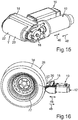
- the maximum outer diameter of the drive roller 20 is particularly good Fig. 19 recognizable and designated there by D max .
- an angle through which the part T extends in circumferential direction of the drive roller 20 about the rotation axis 24 is designated by ⁇ .
- the angle ⁇ is preferably at least 120 degrees, in particular at least 130 degrees and preferably at least 140 degrees or at least 150 degrees.
- the auxiliary drive 10 is particularly flexible in axial Direction of the drive roller 20 are positioned relative to the vehicle, and the drive roller 20, in particular the outer peripheral side surface 22, in the radial direction of the drive roller 20 particularly advantageous in support with the wheel 26, in particular with a tire 36 of the wheel 26 and thereby with a Tread 38 of the tire 36 are moved.
- the transmission 16 includes a plurality of gears 40a-f (FIG. Fig. 8 ) having.
- the respective gears 40a-f are, for example, respective spur gears which mesh with each other, that is, which mesh with each other.
- each two of the gears 40a-f form a respective spur gear.
- the gears 40a-f are arranged in a torque path through which the torque provided by the motor 12 is transmitted to the, and in particular to the drive roller 20, thereby driving the drive roller 20.
- the last spur gear stage in the torque path is also referred to as the last spur gear stage.
- the respective gear 40a-f is rotatable about a respective gear axis of rotation relative to the housing 18, wherein the respective gear axis of rotation perpendicular to the first plane. At least one of the gear axis of rotation may coincide with the axis of rotation 24. Furthermore, it is conceivable that all gear axes of rotation are spaced from the axis of rotation 24.
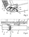
- the gears 40a-e are particularly good Fig. 2 and 3 recognizable, wherein Fig. 2 and 3 show a second embodiment of the auxiliary drive 10.
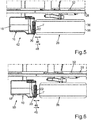
- Fig. 4 and 5 each show in a schematic plan view of a holding arrangement 42 of the auxiliary drive 10, in particular according to the second embodiment, on the vehicle.
- the auxiliary drive 10 has a base element 44, which is fastened to the vehicle, in particular to the frame 32.
- the auxiliary drive 10 is fastened or held on the frame 32 and thus on the vehicle via the base element 44.
- the base member 44 may include the housing 18.
- the drive roller 20 is guided along an inward direction Fig. 4 Movement direction illustrated by a double arrow 46 relative to the base member 44 and thus relative to the frame 32 and thus translationally movable relative to the vehicle.
- the drive roller 20 can be moved translationally relative to the wheel 26 along the direction of movement.
- the drive roller 20 and thus its outer peripheral side surface 22 are spaced from the wheel 26 and in particular from the running surface 38.
- the in Fig. 5 shown drive position are the outer peripheral side surface 22 and thus the drive roller 20 in the radial direction of the drive roller 20 in support system and thus in contact with the tread 38 and thus with the wheel 26.
- the vehicle can be driven by means of the auxiliary drive 10 and thus shunted, for example.
- the direction of movement coincides with the radial direction of the drive roller 20.
- the wheel rotation axis 30 runs perpendicular to the first plane described above, so that, for example, the wheel rotation axis 30 and the rotation axis 24 run parallel to one another.
- the drive roller 20 is in a coincident with the direction of movement and in Fig. 4 illustrated by an arrow 48 support relative to the vehicle and relative to the wheel 26 translationally moved and thereby moved in support with the tread 38.
- the drive roller 20 via its outer peripheral side surface 22 in the coincident with the radial direction of the drive roller 20 supporting direction (arrow 48) in support system with the wheel 26 is movable.
- at least the part T of the outer peripheral side lateral surface 22 projects beyond the housing 18 at least in the supporting direction. This means that the housing 18 does not project beyond the drive roller 20 in the support direction, but is set back in a direction opposite the support direction against at least the portion T and at least 10 millimeters.
- the drive roller 20 In order to move the drive roller 20 located, for example, in the drive position from the drive position to the starting position, the drive roller 20 is moved in the retracted position relative to the frame 32 in translation. As a result, the drive roller 20 of the Wheel 26 moved away. If the drive roller 20 is moved in the support direction, the drive roller 20 is moved toward the wheel 26.
- Fig. 4 It can be seen that, under the feature that at least the part T projects beyond the housing 18 in the radial direction of the drive roller 20 and in the support direction by at least 10 millimeters, it is to be understood that at least the part T of the outer peripheral side surface 22 in the axial direction of the drive roller 20 is arranged without cover to the housing 18. Thus, the portion T in the axial direction of the drive roller 20 is not covered on both sides outwardly by the housing 18.
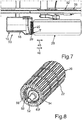
- Fig. 6 and 7 show another holding arrangement 50 of the auxiliary drive 10 on the frame 32 and on the vehicle.
- the difference between the holding arrangements 42 and 50 is that the auxiliary drive 10 is arranged in the holding arrangement 50 in the axial direction of the drive roller 20 and thus in the vehicle transverse direction further outward than in the holding arrangement 42.
- the drive roller 20 can be positioned at least almost freely relative to the wheel 26 along its axial direction.
- the outer peripheral side surface 22 has a plurality of circumferentially of the drive roller 20 successively spaced and spaced teeth, between which respective tooth spaces are arranged.
- a particularly advantageous force and / or positive connection between the drive roller 20 and the tire 36 can be realized in the drive position, so that even very large torques between the drive roller 20 and the wheel 26 can be transmitted.
- the gear 40f is rotatably connected to a shaft 52.
- the gear 40f can be driven by the motor 12 via the shaft 52.
- the gear 40f has an external toothing 54.
- the transmission 16 has at least one ring gear 56 with an internal toothing 58 corresponding, for example, with the external toothing 54.
- the external teeth 54 and the internal teeth 58 are engaged with each other, so that the gear 40f meshes with the external gear 54 and the internal teeth 58 with the ring gear 56.
- the ring gear 56 is rotatably connected to the drive roller 20, and the ring gear 56 is arranged coaxially with the drive roller 20.
- the ring gear 56 and the drive roller 20 are rotatable together or simultaneously about the rotation axis 24 relative to the housing 18.
- the ring gear 56 is completely disposed in the drive roller 20 along its axial direction coincident with the axial direction of the drive roller 20.
- the ring gear 56 is formed integrally with the drive roller 20.
- the gear 40f is rotatable relative to the housing 18 about a gear rotation axis spaced from the rotation axis 24.
- the gear 40f is arranged eccentrically to the drive roller 20 and thus to the ring gear 56.
- the gear 40f is completely disposed in the drive roller 20 along its axial direction. As a result, the space requirement of the transmission 16 can be kept particularly low.
- the gear 40e is also non-rotatably connected to the shaft 52.
- the shaft 52 can be driven by the gear 40e.
- the gear 40f can be driven by the gear 40e via the shaft 52.
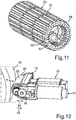
- Fig. 10 It can be seen that at least a portion 60 of the housing 18 projects into the drive roller 20 and is thus at least partially received in the drive roller 20.
- the drive roller 20 via at least or exactly one bearing 62 is rotatably mounted on the part 60 and thus on the housing 18.
- the bearing 62 is preferably a roller bearing, which has a bearing inner ring 64, a bearing outer ring 66 and, for example, roller bodies 68 designed as balls.
- Fig. 10 The aforementioned gear axis, around which the Gears 40e and 40f and the shaft 52 are rotatable relative to the housing 18 is in Fig. 10 recognizable and designated there with 70.
- the gear axis of rotation 70 is spaced from the axis of rotation 24 and thus desachsiert, so that the shaft 52 and the gears 40e and 40f are arranged eccentrically to the drive roller 20.
- This arrangement can be particularly good Fig. 11 be recognized.
- FIG. 12 shows the auxiliary drive 10 according to the first embodiment, wherein the drive roller 20 is in the drive position and thus in support system with the tire 36.
- FIGS. 13 and 14 show a further schematic perspective view of the auxiliary drive 10 according to the second embodiment, wherein Fig. 15 and 17 show further perspective views of the auxiliary drive 10 according to the first embodiment.
- the wheel 26 which includes the tire 36 and a rim 72.
- the tire 36 is mounted on the rim 72, that is arranged on the rim 72.
- Fig. 18 shows the auxiliary drive 10 in a schematic plan view, wherein the drive roller 20 is in support system with the tread 38.
- the drive roller 20 can be positioned at least almost freely or arbitrarily along the axial direction of the drive roller 20 relative to the wheel 26, the drive roller 20, in particular its outer peripheral side surface 22, in a particularly advantageous and extensive or extensive contact with the tread 38th to be brought. As a result, even very large torques can be transmitted from the drive roller 20 to the wheel 26.
- the transmission 16 comprises a crank drive 74, also referred to as a crank drive, via which the drive roller 20 can be driven by the motor 12.
- the crank drive 74 comprises at least one articulated and thereby eccentrically coupled to the drive roller 20 crank 76 which is coupled so articulated and eccentric with the drive roller 20 that the crank 76 with the drive roller 20 about an axis of rotation 78 relative to the drive roller 20 rotatable is coupled, wherein the axis of rotation 78 is parallel to the axis of rotation 24 and spaced therefrom.
- the crank 76 for example, coupled with an eccentric crank or with an eccentric shaft.
- the crank 76 When the eccentric shaft is rotated, for example, the crank 76 is reciprocated oscillatingly relative to the drive roller 20, whereby the rotation axis 78 is rotated about the rotation axis 24. As a result, the drive roller 20 is rotated about the rotation axis 24 relative to the housing 18.
- the motor 12 is at least partially, in particular at least predominantly or completely, received in the housing 18.
- a brake in particular with a mechanical brake.
- the drive roller 20, in particular via the gear 16 can be secured against rotation relative to the housing 18 about the axis of rotation 24.
- a non-self-locking transmission that is, a transmission without self-locking can be used.
- the space requirements, the weight and the cost can be kept in a very small frame.
Landscapes
- Engineering & Computer Science (AREA)
- Chemical & Material Sciences (AREA)
- Combustion & Propulsion (AREA)
- Transportation (AREA)
- Mechanical Engineering (AREA)
- Arrangement Or Mounting Of Propulsion Units For Vehicles (AREA)
- Friction Gearing (AREA)
Priority Applications (1)
| Application Number | Priority Date | Filing Date | Title |
|---|---|---|---|
| EP23183426.8A EP4242090A1 (fr) | 2018-04-10 | 2019-04-05 | Entraînement auxiliaire pour un véhicule, en particulier pour une remorque, ainsi que remorque |
Applications Claiming Priority (1)
| Application Number | Priority Date | Filing Date | Title |
|---|---|---|---|
| DE202018101924.4U DE202018101924U1 (de) | 2018-04-10 | 2018-04-10 | Hilfsantrieb für ein Fahrzeug, insbesondere für einen Anhänger, sowie Anhänger |
Related Child Applications (1)
| Application Number | Title | Priority Date | Filing Date |
|---|---|---|---|
| EP23183426.8A Division EP4242090A1 (fr) | 2018-04-10 | 2019-04-05 | Entraînement auxiliaire pour un véhicule, en particulier pour une remorque, ainsi que remorque |
Publications (2)
| Publication Number | Publication Date |
|---|---|
| EP3552932A1 true EP3552932A1 (fr) | 2019-10-16 |
| EP3552932B1 EP3552932B1 (fr) | 2023-07-19 |
Family
ID=66101983
Family Applications (2)
| Application Number | Title | Priority Date | Filing Date |
|---|---|---|---|
| EP23183426.8A Pending EP4242090A1 (fr) | 2018-04-10 | 2019-04-05 | Entraînement auxiliaire pour un véhicule, en particulier pour une remorque, ainsi que remorque |
| EP19167634.5A Active EP3552932B1 (fr) | 2018-04-10 | 2019-04-05 | Entraînement auxiliaire pour un véhicule, en particulier pour une remorque, ainsi que remorque |
Family Applications Before (1)
| Application Number | Title | Priority Date | Filing Date |
|---|---|---|---|
| EP23183426.8A Pending EP4242090A1 (fr) | 2018-04-10 | 2019-04-05 | Entraînement auxiliaire pour un véhicule, en particulier pour une remorque, ainsi que remorque |
Country Status (2)
| Country | Link |
|---|---|
| EP (2) | EP4242090A1 (fr) |
| DE (1) | DE202018101924U1 (fr) |
Cited By (1)
| Publication number | Priority date | Publication date | Assignee | Title |
|---|---|---|---|---|
| EP4592167A1 (fr) | 2024-01-29 | 2025-07-30 | Alois Kober GmbH | Unité d'entraînement et procédé d'entraînement |
Families Citing this family (1)
| Publication number | Priority date | Publication date | Assignee | Title |
|---|---|---|---|---|
| DE102022103607A1 (de) | 2022-02-16 | 2023-08-17 | Frank Heil | Anhängehilfe für einen Fahrzeuganhänger |
Citations (6)
| Publication number | Priority date | Publication date | Assignee | Title |
|---|---|---|---|---|
| GB2457725A (en) * | 2008-02-25 | 2009-08-26 | James Richard Yates | Machines for manoeuvring trailers |
| EP2208661A1 (fr) * | 2009-01-16 | 2010-07-21 | Truma Gerätetechnik GmbH & Co. KG | Entraînement de rangement pour remorques de véhicules |
| FR2965539A1 (fr) * | 2010-10-05 | 2012-04-06 | Queguiner Alain Francois Joseph | Entrainement motorise sous 220 v pour remorque |
| DE202014100738U1 (de) * | 2014-02-19 | 2014-03-20 | Truma Gerätetechnik GmbH & Co. KG | Rangierantrieb mit Spritzschutz für Anhänder oder dgl. |
| EP2952421A2 (fr) * | 2014-03-31 | 2015-12-09 | Reich KG, Regel- und Sicherheitstechnik | Entraînement d'assistance pour une remorque et remorque |
| CN205365801U (zh) * | 2016-01-27 | 2016-07-06 | 杭州嘉迈机械有限公司 | 一种手动式拖车推进器 |
Family Cites Families (4)
| Publication number | Priority date | Publication date | Assignee | Title |
|---|---|---|---|---|
| GB2447069B (en) * | 2007-02-27 | 2009-02-18 | Mark Darren Shaw | Composite, plasic/resin caravan/trailer mover with tongue and groove sliding mechanism |
| GB2450863B (en) | 2007-06-12 | 2009-09-09 | Mark Darren Shaw | Drive friction motor roller |
| DE202009001675U1 (de) | 2008-06-25 | 2009-11-26 | Al-Ko Kober Ag | Hilfsantrieb |
| DE202015105911U1 (de) * | 2015-11-05 | 2016-01-12 | Truma Gerätetechnik GmbH & Co. KG | Rangierantrieb für einen Anhänger |
-
2018
- 2018-04-10 DE DE202018101924.4U patent/DE202018101924U1/de active Active
-
2019
- 2019-04-05 EP EP23183426.8A patent/EP4242090A1/fr active Pending
- 2019-04-05 EP EP19167634.5A patent/EP3552932B1/fr active Active
Patent Citations (6)
| Publication number | Priority date | Publication date | Assignee | Title |
|---|---|---|---|---|
| GB2457725A (en) * | 2008-02-25 | 2009-08-26 | James Richard Yates | Machines for manoeuvring trailers |
| EP2208661A1 (fr) * | 2009-01-16 | 2010-07-21 | Truma Gerätetechnik GmbH & Co. KG | Entraînement de rangement pour remorques de véhicules |
| FR2965539A1 (fr) * | 2010-10-05 | 2012-04-06 | Queguiner Alain Francois Joseph | Entrainement motorise sous 220 v pour remorque |
| DE202014100738U1 (de) * | 2014-02-19 | 2014-03-20 | Truma Gerätetechnik GmbH & Co. KG | Rangierantrieb mit Spritzschutz für Anhänder oder dgl. |
| EP2952421A2 (fr) * | 2014-03-31 | 2015-12-09 | Reich KG, Regel- und Sicherheitstechnik | Entraînement d'assistance pour une remorque et remorque |
| CN205365801U (zh) * | 2016-01-27 | 2016-07-06 | 杭州嘉迈机械有限公司 | 一种手动式拖车推进器 |
Cited By (1)
| Publication number | Priority date | Publication date | Assignee | Title |
|---|---|---|---|---|
| EP4592167A1 (fr) | 2024-01-29 | 2025-07-30 | Alois Kober GmbH | Unité d'entraînement et procédé d'entraînement |
Also Published As
| Publication number | Publication date |
|---|---|
| DE202018101924U1 (de) | 2019-04-11 |
| EP4242090A1 (fr) | 2023-09-13 |
| EP3552932B1 (fr) | 2023-07-19 |
Similar Documents
| Publication | Publication Date | Title |
|---|---|---|
| DE112010004408B4 (de) | Elektromotor mit Planetengetriebesatz mit mehreren, durch Einbauorientierung der Komponenten wählbaren Übersetzungen | |
| DE69825917T2 (de) | Antriebseinheit für ein elektrisch angetriebenes Niederflurfahrzeug | |
| DE3027806C2 (de) | Triebachse für Omnibusse | |
| DE102007060149A1 (de) | Teleskopierbare Lenkspindelanordnung | |
| DE102012219212A1 (de) | Differentialgetriebe | |
| DE102009046080A1 (de) | Getriebe-Antriebseinheit | |
| DE102008058853A1 (de) | Flexible Verbindung für eine motorbetriebene Servolenkung | |
| DE102016210578B4 (de) | Wellenkupplungsanordnung | |
| WO2016091512A1 (fr) | Unité d'entraînement pour un chariot de manutention et chariot de manutention | |
| EP3165433B1 (fr) | Entraînement de rangement pour remorque | |
| DE102009047730A1 (de) | Lenkbare Antriebsanordnung für ein Flurförderfahrzeug | |
| DE102011082671A1 (de) | Antriebseinheit für ein Flurförderzeug | |
| DE4217414C2 (de) | Achslager, insbesondere Radachslager für Kraftfahrzeuge | |
| EP3552932B1 (fr) | Entraînement auxiliaire pour un véhicule, en particulier pour une remorque, ainsi que remorque | |
| EP2669155B1 (fr) | Entraînement de rangement pour remorque avec engrenage doté d'un agencement d'axes non parallèles | |
| EP3527845B1 (fr) | Ensemble de palier d'un engrenage planétaire à roue hélicoïdale | |
| DE7916783U1 (de) | Strebe für die Radaufhängung eines Kraftfahrzeuges | |
| DE19840006A1 (de) | Flurförderzeug, insbesondere Hubgabelstapler, und zugeordnete Achs-Motor-Einheit | |
| DE102016212818A1 (de) | Lenkung für Fahrzeuge mit Hochübersetzungsgetriebe, insbesondere für Nutzkraftfahrzeuge | |
| DE102015122515B4 (de) | Reduktionsgetriebe | |
| DE102018114267A1 (de) | Elektromechanische Servolenkung mit einem Schraubradgetriebe und einem Getriebegehäuse | |
| DE102014218737A1 (de) | Zweistufiges Planetengetriebe zur Untersetzung hoher Drehzahlen | |
| DE112021001375T5 (de) | Integriertes Antriebssystem und Elektrofahrzeug | |
| DE102019131735A1 (de) | Laufrolle mit integriertem Elektromotor und Planetengetriebe | |
| DE102014106255A1 (de) | Überlagerungslenkung |
Legal Events
| Date | Code | Title | Description |
|---|---|---|---|
| PUAI | Public reference made under article 153(3) epc to a published international application that has entered the european phase |
Free format text: ORIGINAL CODE: 0009012 |
|
| STAA | Information on the status of an ep patent application or granted ep patent |
Free format text: STATUS: THE APPLICATION HAS BEEN PUBLISHED |
|
| AK | Designated contracting states |
Kind code of ref document: A1 Designated state(s): AL AT BE BG CH CY CZ DE DK EE ES FI FR GB GR HR HU IE IS IT LI LT LU LV MC MK MT NL NO PL PT RO RS SE SI SK SM TR |
|
| AX | Request for extension of the european patent |
Extension state: BA ME |
|
| STAA | Information on the status of an ep patent application or granted ep patent |
Free format text: STATUS: REQUEST FOR EXAMINATION WAS MADE |
|
| 17P | Request for examination filed |
Effective date: 20200407 |
|
| RBV | Designated contracting states (corrected) |
Designated state(s): AL AT BE BG CH CY CZ DE DK EE ES FI FR GB GR HR HU IE IS IT LI LT LU LV MC MK MT NL NO PL PT RO RS SE SI SK SM TR |
|
| RIN1 | Information on inventor provided before grant (corrected) |
Inventor name: WELLE, RUDOLF Inventor name: BEIJERSBERGEN VAN HENEGOUWEN, CORNELIS MARTIN Inventor name: SCHAURER, OLIVER Inventor name: KUNZ, THOMAS Inventor name: BENDER, STEFFEN |
|
| STAA | Information on the status of an ep patent application or granted ep patent |
Free format text: STATUS: EXAMINATION IS IN PROGRESS |
|
| 17Q | First examination report despatched |
Effective date: 20201103 |
|
| GRAP | Despatch of communication of intention to grant a patent |
Free format text: ORIGINAL CODE: EPIDOSNIGR1 |
|
| STAA | Information on the status of an ep patent application or granted ep patent |
Free format text: STATUS: GRANT OF PATENT IS INTENDED |
|
| INTG | Intention to grant announced |
Effective date: 20230131 |
|
| GRAS | Grant fee paid |
Free format text: ORIGINAL CODE: EPIDOSNIGR3 |
|
| GRAA | (expected) grant |
Free format text: ORIGINAL CODE: 0009210 |
|
| STAA | Information on the status of an ep patent application or granted ep patent |
Free format text: STATUS: THE PATENT HAS BEEN GRANTED |
|
| P01 | Opt-out of the competence of the unified patent court (upc) registered |
Effective date: 20230607 |
|
| AK | Designated contracting states |
Kind code of ref document: B1 Designated state(s): AL AT BE BG CH CY CZ DE DK EE ES FI FR GB GR HR HU IE IS IT LI LT LU LV MC MK MT NL NO PL PT RO RS SE SI SK SM TR |
|
| REG | Reference to a national code |
Ref country code: GB Ref legal event code: FG4D Free format text: NOT ENGLISH |
|
| REG | Reference to a national code |
Ref country code: CH Ref legal event code: EP |
|
| REG | Reference to a national code |
Ref country code: DE Ref legal event code: R096 Ref document number: 502019008559 Country of ref document: DE |
|
| REG | Reference to a national code |
Ref country code: IE Ref legal event code: FG4D Free format text: LANGUAGE OF EP DOCUMENT: GERMAN |
|
| REG | Reference to a national code |
Ref country code: NL Ref legal event code: FP |
|
| REG | Reference to a national code |
Ref country code: SE Ref legal event code: TRGR |
|
| REG | Reference to a national code |
Ref country code: LT Ref legal event code: MG9D |
|
| REG | Reference to a national code |
Ref country code: DE Ref legal event code: R026 Ref document number: 502019008559 Country of ref document: DE |
|
| PLBI | Opposition filed |
Free format text: ORIGINAL CODE: 0009260 |
|
| 26 | Opposition filed |
Opponent name: TRUMA GERAETETECHNIK GMBH & CO. KG Effective date: 20231122 |
|
| PG25 | Lapsed in a contracting state [announced via postgrant information from national office to epo] |
Ref country code: GR Free format text: LAPSE BECAUSE OF FAILURE TO SUBMIT A TRANSLATION OF THE DESCRIPTION OR TO PAY THE FEE WITHIN THE PRESCRIBED TIME-LIMIT Effective date: 20231020 |
|
| PG25 | Lapsed in a contracting state [announced via postgrant information from national office to epo] |
Ref country code: IS Free format text: LAPSE BECAUSE OF FAILURE TO SUBMIT A TRANSLATION OF THE DESCRIPTION OR TO PAY THE FEE WITHIN THE PRESCRIBED TIME-LIMIT Effective date: 20231119 |
|
| PG25 | Lapsed in a contracting state [announced via postgrant information from national office to epo] |
Ref country code: RS Free format text: LAPSE BECAUSE OF FAILURE TO SUBMIT A TRANSLATION OF THE DESCRIPTION OR TO PAY THE FEE WITHIN THE PRESCRIBED TIME-LIMIT Effective date: 20230719 Ref country code: PT Free format text: LAPSE BECAUSE OF FAILURE TO SUBMIT A TRANSLATION OF THE DESCRIPTION OR TO PAY THE FEE WITHIN THE PRESCRIBED TIME-LIMIT Effective date: 20231120 Ref country code: NO Free format text: LAPSE BECAUSE OF FAILURE TO SUBMIT A TRANSLATION OF THE DESCRIPTION OR TO PAY THE FEE WITHIN THE PRESCRIBED TIME-LIMIT Effective date: 20231019 Ref country code: LV Free format text: LAPSE BECAUSE OF FAILURE TO SUBMIT A TRANSLATION OF THE DESCRIPTION OR TO PAY THE FEE WITHIN THE PRESCRIBED TIME-LIMIT Effective date: 20230719 Ref country code: LT Free format text: LAPSE BECAUSE OF FAILURE TO SUBMIT A TRANSLATION OF THE DESCRIPTION OR TO PAY THE FEE WITHIN THE PRESCRIBED TIME-LIMIT Effective date: 20230719 Ref country code: IS Free format text: LAPSE BECAUSE OF FAILURE TO SUBMIT A TRANSLATION OF THE DESCRIPTION OR TO PAY THE FEE WITHIN THE PRESCRIBED TIME-LIMIT Effective date: 20231119 Ref country code: HR Free format text: LAPSE BECAUSE OF FAILURE TO SUBMIT A TRANSLATION OF THE DESCRIPTION OR TO PAY THE FEE WITHIN THE PRESCRIBED TIME-LIMIT Effective date: 20230719 Ref country code: GR Free format text: LAPSE BECAUSE OF FAILURE TO SUBMIT A TRANSLATION OF THE DESCRIPTION OR TO PAY THE FEE WITHIN THE PRESCRIBED TIME-LIMIT Effective date: 20231020 Ref country code: FI Free format text: LAPSE BECAUSE OF FAILURE TO SUBMIT A TRANSLATION OF THE DESCRIPTION OR TO PAY THE FEE WITHIN THE PRESCRIBED TIME-LIMIT Effective date: 20230719 |
|
| PG25 | Lapsed in a contracting state [announced via postgrant information from national office to epo] |
Ref country code: PL Free format text: LAPSE BECAUSE OF FAILURE TO SUBMIT A TRANSLATION OF THE DESCRIPTION OR TO PAY THE FEE WITHIN THE PRESCRIBED TIME-LIMIT Effective date: 20230719 |
|
| PG25 | Lapsed in a contracting state [announced via postgrant information from national office to epo] |
Ref country code: ES Free format text: LAPSE BECAUSE OF FAILURE TO SUBMIT A TRANSLATION OF THE DESCRIPTION OR TO PAY THE FEE WITHIN THE PRESCRIBED TIME-LIMIT Effective date: 20230719 |
|
| PG25 | Lapsed in a contracting state [announced via postgrant information from national office to epo] |
Ref country code: SM Free format text: LAPSE BECAUSE OF FAILURE TO SUBMIT A TRANSLATION OF THE DESCRIPTION OR TO PAY THE FEE WITHIN THE PRESCRIBED TIME-LIMIT Effective date: 20230719 Ref country code: RO Free format text: LAPSE BECAUSE OF FAILURE TO SUBMIT A TRANSLATION OF THE DESCRIPTION OR TO PAY THE FEE WITHIN THE PRESCRIBED TIME-LIMIT Effective date: 20230719 Ref country code: ES Free format text: LAPSE BECAUSE OF FAILURE TO SUBMIT A TRANSLATION OF THE DESCRIPTION OR TO PAY THE FEE WITHIN THE PRESCRIBED TIME-LIMIT Effective date: 20230719 Ref country code: EE Free format text: LAPSE BECAUSE OF FAILURE TO SUBMIT A TRANSLATION OF THE DESCRIPTION OR TO PAY THE FEE WITHIN THE PRESCRIBED TIME-LIMIT Effective date: 20230719 Ref country code: DK Free format text: LAPSE BECAUSE OF FAILURE TO SUBMIT A TRANSLATION OF THE DESCRIPTION OR TO PAY THE FEE WITHIN THE PRESCRIBED TIME-LIMIT Effective date: 20230719 Ref country code: CZ Free format text: LAPSE BECAUSE OF FAILURE TO SUBMIT A TRANSLATION OF THE DESCRIPTION OR TO PAY THE FEE WITHIN THE PRESCRIBED TIME-LIMIT Effective date: 20230719 Ref country code: SK Free format text: LAPSE BECAUSE OF FAILURE TO SUBMIT A TRANSLATION OF THE DESCRIPTION OR TO PAY THE FEE WITHIN THE PRESCRIBED TIME-LIMIT Effective date: 20230719 |
|
| PLAX | Notice of opposition and request to file observation + time limit sent |
Free format text: ORIGINAL CODE: EPIDOSNOBS2 |
|
| PG25 | Lapsed in a contracting state [announced via postgrant information from national office to epo] |
Ref country code: IT Free format text: LAPSE BECAUSE OF FAILURE TO SUBMIT A TRANSLATION OF THE DESCRIPTION OR TO PAY THE FEE WITHIN THE PRESCRIBED TIME-LIMIT Effective date: 20230719 |
|
| PG25 | Lapsed in a contracting state [announced via postgrant information from national office to epo] |
Ref country code: SI Free format text: LAPSE BECAUSE OF FAILURE TO SUBMIT A TRANSLATION OF THE DESCRIPTION OR TO PAY THE FEE WITHIN THE PRESCRIBED TIME-LIMIT Effective date: 20230719 |
|
| PLBB | Reply of patent proprietor to notice(s) of opposition received |
Free format text: ORIGINAL CODE: EPIDOSNOBS3 |
|
| PG25 | Lapsed in a contracting state [announced via postgrant information from national office to epo] |
Ref country code: BG Free format text: LAPSE BECAUSE OF FAILURE TO SUBMIT A TRANSLATION OF THE DESCRIPTION OR TO PAY THE FEE WITHIN THE PRESCRIBED TIME-LIMIT Effective date: 20230719 |
|
| PG25 | Lapsed in a contracting state [announced via postgrant information from national office to epo] |
Ref country code: MC Free format text: LAPSE BECAUSE OF FAILURE TO SUBMIT A TRANSLATION OF THE DESCRIPTION OR TO PAY THE FEE WITHIN THE PRESCRIBED TIME-LIMIT Effective date: 20230719 |
|
| PG25 | Lapsed in a contracting state [announced via postgrant information from national office to epo] |
Ref country code: MC Free format text: LAPSE BECAUSE OF FAILURE TO SUBMIT A TRANSLATION OF THE DESCRIPTION OR TO PAY THE FEE WITHIN THE PRESCRIBED TIME-LIMIT Effective date: 20230719 Ref country code: BG Free format text: LAPSE BECAUSE OF FAILURE TO SUBMIT A TRANSLATION OF THE DESCRIPTION OR TO PAY THE FEE WITHIN THE PRESCRIBED TIME-LIMIT Effective date: 20230719 |
|
| REG | Reference to a national code |
Ref country code: CH Ref legal event code: PL |
|
| PG25 | Lapsed in a contracting state [announced via postgrant information from national office to epo] |
Ref country code: LU Free format text: LAPSE BECAUSE OF NON-PAYMENT OF DUE FEES Effective date: 20240405 |
|
| REG | Reference to a national code |
Ref country code: BE Ref legal event code: MM Effective date: 20240430 |
|
| PG25 | Lapsed in a contracting state [announced via postgrant information from national office to epo] |
Ref country code: LU Free format text: LAPSE BECAUSE OF NON-PAYMENT OF DUE FEES Effective date: 20240405 |
|
| PG25 | Lapsed in a contracting state [announced via postgrant information from national office to epo] |
Ref country code: BE Free format text: LAPSE BECAUSE OF NON-PAYMENT OF DUE FEES Effective date: 20240430 |
|
| PG25 | Lapsed in a contracting state [announced via postgrant information from national office to epo] |
Ref country code: BE Free format text: LAPSE BECAUSE OF NON-PAYMENT OF DUE FEES Effective date: 20240430 Ref country code: CH Free format text: LAPSE BECAUSE OF NON-PAYMENT OF DUE FEES Effective date: 20240430 |
|
| PG25 | Lapsed in a contracting state [announced via postgrant information from national office to epo] |
Ref country code: IE Free format text: LAPSE BECAUSE OF NON-PAYMENT OF DUE FEES Effective date: 20240405 |
|
| PGFP | Annual fee paid to national office [announced via postgrant information from national office to epo] |
Ref country code: NL Payment date: 20250422 Year of fee payment: 7 |
|
| REG | Reference to a national code |
Ref country code: AT Ref legal event code: MM01 Ref document number: 1589210 Country of ref document: AT Kind code of ref document: T Effective date: 20240405 |
|
| PGFP | Annual fee paid to national office [announced via postgrant information from national office to epo] |
Ref country code: DE Payment date: 20250425 Year of fee payment: 7 |
|
| PGFP | Annual fee paid to national office [announced via postgrant information from national office to epo] |
Ref country code: FR Payment date: 20250422 Year of fee payment: 7 |
|
| PG25 | Lapsed in a contracting state [announced via postgrant information from national office to epo] |
Ref country code: AT Free format text: LAPSE BECAUSE OF NON-PAYMENT OF DUE FEES Effective date: 20240405 |
|
| PGFP | Annual fee paid to national office [announced via postgrant information from national office to epo] |
Ref country code: SE Payment date: 20250423 Year of fee payment: 7 |
|
| PG25 | Lapsed in a contracting state [announced via postgrant information from national office to epo] |
Ref country code: CY Free format text: LAPSE BECAUSE OF FAILURE TO SUBMIT A TRANSLATION OF THE DESCRIPTION OR TO PAY THE FEE WITHIN THE PRESCRIBED TIME-LIMIT; INVALID AB INITIO Effective date: 20190405 |
|
| PG25 | Lapsed in a contracting state [announced via postgrant information from national office to epo] |
Ref country code: HU Free format text: LAPSE BECAUSE OF FAILURE TO SUBMIT A TRANSLATION OF THE DESCRIPTION OR TO PAY THE FEE WITHIN THE PRESCRIBED TIME-LIMIT; INVALID AB INITIO Effective date: 20190405 |
|
| PG25 | Lapsed in a contracting state [announced via postgrant information from national office to epo] |
Ref country code: TR Free format text: LAPSE BECAUSE OF FAILURE TO SUBMIT A TRANSLATION OF THE DESCRIPTION OR TO PAY THE FEE WITHIN THE PRESCRIBED TIME-LIMIT Effective date: 20230719 |
|
| PGFP | Annual fee paid to national office [announced via postgrant information from national office to epo] |
Ref country code: GB Payment date: 20260324 Year of fee payment: 8 |