EP3552951A1 - Schalldämmplatte für luftfahrzeug, die kombinierte schallabsorptionseigenschaften aufweist - Google Patents
Schalldämmplatte für luftfahrzeug, die kombinierte schallabsorptionseigenschaften aufweist Download PDFInfo
- Publication number
- EP3552951A1 EP3552951A1 EP19167450.6A EP19167450A EP3552951A1 EP 3552951 A1 EP3552951 A1 EP 3552951A1 EP 19167450 A EP19167450 A EP 19167450A EP 3552951 A1 EP3552951 A1 EP 3552951A1
- Authority
- EP
- European Patent Office
- Prior art keywords
- acoustic
- auxiliary
- cavity
- skin
- panel
- Prior art date
- Legal status (The legal status is an assumption and is not a legal conclusion. Google has not performed a legal analysis and makes no representation as to the accuracy of the status listed.)
- Granted
Links
Images

Classifications
-
- F—MECHANICAL ENGINEERING; LIGHTING; HEATING; WEAPONS; BLASTING
- F02—COMBUSTION ENGINES; HOT-GAS OR COMBUSTION-PRODUCT ENGINE PLANTS
- F02C—GAS-TURBINE PLANTS; AIR INTAKES FOR JET-PROPULSION PLANTS; CONTROLLING FUEL SUPPLY IN AIR-BREATHING JET-PROPULSION PLANTS
- F02C7/00—Features, components parts, details or accessories, not provided for in, or of interest apart form groups F02C1/00 - F02C6/00; Air intakes for jet-propulsion plants
- F02C7/04—Air intakes for gas-turbine plants or jet-propulsion plants
- F02C7/045—Air intakes for gas-turbine plants or jet-propulsion plants having provisions for noise suppression
-
- B—PERFORMING OPERATIONS; TRANSPORTING
- B64—AIRCRAFT; AVIATION; COSMONAUTICS
- B64D—EQUIPMENT FOR FITTING IN OR TO AIRCRAFT; FLIGHT SUITS; PARACHUTES; ARRANGEMENT OR MOUNTING OF POWER PLANTS OR PROPULSION TRANSMISSIONS IN AIRCRAFT
- B64D33/00—Arrangement in aircraft of power plant parts or auxiliaries not otherwise provided for
- B64D33/02—Arrangement in aircraft of power plant parts or auxiliaries not otherwise provided for of combustion air intakes
-
- B—PERFORMING OPERATIONS; TRANSPORTING
- B64—AIRCRAFT; AVIATION; COSMONAUTICS
- B64G—COSMONAUTICS; VEHICLES OR EQUIPMENT THEREFOR
- B64G1/00—Cosmonautic vehicles
- B64G1/22—Parts of, or equipment specially adapted for fitting in or to, cosmonautic vehicles
-
- G—PHYSICS
- G10—MUSICAL INSTRUMENTS; ACOUSTICS
- G10K—SOUND-PRODUCING DEVICES; METHODS OR DEVICES FOR PROTECTING AGAINST, OR FOR DAMPING, NOISE OR OTHER ACOUSTIC WAVES IN GENERAL; ACOUSTICS NOT OTHERWISE PROVIDED FOR
- G10K11/00—Methods or devices for transmitting, conducting or directing sound in general; Methods or devices for protecting against, or for damping, noise or other acoustic waves in general
- G10K11/16—Methods or devices for protecting against, or for damping, noise or other acoustic waves in general
-
- G—PHYSICS
- G10—MUSICAL INSTRUMENTS; ACOUSTICS
- G10K—SOUND-PRODUCING DEVICES; METHODS OR DEVICES FOR PROTECTING AGAINST, OR FOR DAMPING, NOISE OR OTHER ACOUSTIC WAVES IN GENERAL; ACOUSTICS NOT OTHERWISE PROVIDED FOR
- G10K11/00—Methods or devices for transmitting, conducting or directing sound in general; Methods or devices for protecting against, or for damping, noise or other acoustic waves in general
- G10K11/16—Methods or devices for protecting against, or for damping, noise or other acoustic waves in general
- G10K11/162—Selection of materials
-
- B—PERFORMING OPERATIONS; TRANSPORTING
- B64—AIRCRAFT; AVIATION; COSMONAUTICS
- B64D—EQUIPMENT FOR FITTING IN OR TO AIRCRAFT; FLIGHT SUITS; PARACHUTES; ARRANGEMENT OR MOUNTING OF POWER PLANTS OR PROPULSION TRANSMISSIONS IN AIRCRAFT
- B64D33/00—Arrangement in aircraft of power plant parts or auxiliaries not otherwise provided for
- B64D33/02—Arrangement in aircraft of power plant parts or auxiliaries not otherwise provided for of combustion air intakes
- B64D2033/0206—Arrangement in aircraft of power plant parts or auxiliaries not otherwise provided for of combustion air intakes comprising noise reduction means, e.g. acoustic liners
-
- F—MECHANICAL ENGINEERING; LIGHTING; HEATING; WEAPONS; BLASTING
- F05—INDEXING SCHEMES RELATING TO ENGINES OR PUMPS IN VARIOUS SUBCLASSES OF CLASSES F01-F04
- F05D—INDEXING SCHEME FOR ASPECTS RELATING TO NON-POSITIVE-DISPLACEMENT MACHINES OR ENGINES, GAS-TURBINES OR JET-PROPULSION PLANTS
- F05D2260/00—Function
- F05D2260/96—Preventing, counteracting or reducing vibration or noise
Definitions
- the present invention relates to an acoustic attenuation panel for aircraft, and in particular for a reactor nacelle hood of an aircraft.
- an acoustic attenuation panel generally comprises an acoustic structure provided with a plate made of a material and / or a structure having good acoustic absorption properties, in particular for the frequencies most annoying noises.
- This structure used for acoustic absorption can therefore be of cellular material but also based on foam or fibrous material.
- This plate often has, for this purpose, honeycomb honeycomb structure for most panels, and is provided on both sides, respectively, with a so-called resistive skin ("resistive skin” in English) often perforated and a non-perforated back skin (“backing skin” in English).
- the acoustic panel is arranged so that the resistive skin is located close to the noise source, in particular upstream and / or downstream of the fan ("fan" in English) in the case of an aircraft reactor, for perform an effective absorption of the noise generated upstream and downstream of the fan.
- the size of the cells (section and height) of the honeycomb structure is generally adapted to the frequency of the noise to be absorbed.
- a propulsion unit of an aircraft more particularly comprises an air intake which is provided with such an acoustic panel.
- This air intake must in particular provide acoustic treatment of the front portion of the propulsion unit and absorb noise from the blower of the propulsion unit.
- the acoustic panel mainly provides acoustic treatment and much of the internal aerodynamics.
- the front and rear parts of the acoustic panel have no acoustic property. Indeed, they have the sole function of fixing the acoustic panel. It therefore appears a loss of sound absorption capacity to these front and rear parts.
- the constructive principle of the acoustic panel does not make these front and rear parts, having a bevel shape, acoustically absorbing like the rest of the panel by adding for example a cellular material.
- the object of the present invention is to improve the acoustic absorption properties of an acoustic panel, in particular of an air intake of a propulsion unit, in particular by increasing the acoustic surface.
- the present invention relates to an acoustic panel for an aircraft, and in particular for a nacelle of a propulsion unit (or reactor) of the aircraft, said acoustic panel comprising an acoustic structure provided with an inner skin with a controlled porosity called a resistive skin, a honeycomb structure and a so-called back skin, reflective in the alveolar zone.
- said acoustic panel comprises at least one auxiliary acoustic cavity device configured to achieve acoustic absorption, preferably targeting low frequencies, while keeping a rear skin approximately at the same height (between 0 and + 30% more height of the cells of the honeycomb structure) than the right waveguide alveolar structures, said auxiliary acoustic cavity device being integral with said acoustic structure, said auxiliary acoustic device to cavities comprising a plurality of adjacent chambers (or cavities) separated by adjoining walls, each of said (axillary) chambers preferably having a volume significantly larger than a cell of the honeycomb structure (ie between 3 and 30 times), and being provided with perforations able to achieve an acoustic absorption.
- At least one auxiliary acoustic device is added to the acoustic structure.
- the combination of the cellular acoustic structure and the cavity auxiliary acoustic device makes it possible to combine the acoustic absorption properties of the two types of acoustic absorption and of frequencies, and thus to increase the overall acoustic absorption of the acoustic panel, ie more to provide acoustic elements adapted to sources of noise that are not absorbed by the single honeycomb acoustic structure.
- Said acoustic panel and in particular the combination of the cellular acoustic structure and the auxiliary acoustic device can be made in different ways.
- the acoustic panel therefore comprises an acoustic structure provided with a cellular structure as well as a so-called resistive skin (or front skin) and a so-called rear skin arranged, respectively, on either side of this structure.
- the acoustic panel comprising at least one auxiliary acoustic device with cavities configured to achieve acoustic absorption, said auxiliary cavity-type acoustic device being integral with said acoustic structure, said auxiliary cavity-type acoustic device comprising a plurality of adjacent chambers separated by walls terraced, each of said chambers being provided with perforations and being able to achieve an acoustic absorption.
- the auxiliary acoustic cavity device is arranged on a peripheral edge of the acoustic structure where the acoustic panel comprises an end portion for fixing said acoustic panel.
- the perforations are provided on a front face of the auxiliary cavity acoustic device, that is to say on the same side as the perforations of the resistive skin (front skin).
- said cellular acoustic structure and said auxiliary acoustic device form a single piece.
- the auxiliary acoustic device is fixed on the acoustic structure.
- said at least one auxiliary acoustic device is arranged at least on a portion of at least one peripheral edge of the acoustic structure.
- the acoustic panel is advantageously provided with at least two auxiliary acoustic devices arranged, respectively, on at least two peripheral edges of the acoustic structure or on at least two sections of a peripheral edge of the acoustic structure.
- the auxiliary acoustic device comprises at least one so-called perforated face provided with said perforations and said perforated face is arranged on the same side of the acoustic panel as the resistive skin.
- the chambers of the auxiliary acoustic device can be made in different ways.
- they are provided with perforations (or micro-perforations) having reduced surfaces, of size included in a circle of diameter between 0.2 and 1 millimeters.
- the auxiliary acoustic device comprises chambers of identical volume.
- the cavity-type auxiliary acoustic device comprises chambers (or cavities) of several different types, in particular having different chamber volumes and / or (global) perforation surfaces per chamber, which are different.
- Each cavity type or chamber is configured to provide a preferred acoustic absorption in at least a given acoustic frequency range.
- At least the volume of the chamber and the surface of the perforations of the chamber are adapted to give the chamber a preferred acoustic absorption in at least a given acoustic frequency range.
- the present invention also relates to a method of manufacturing an acoustic panel, such as that described above.
- said manufacturing method comprises a plurality of successive steps comprising at least one firing and configured to manufacture an acoustic panel comprising a cellular acoustic structure, as well as a so-called resistive skin and a so-called back skin and at least one auxiliary acoustic device (with large chambers or cavities).
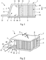
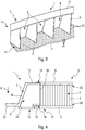
- the acoustic panel 1 (or sound attenuation panel) shown schematically in a first (preferred) embodiment on the Figures 1 to 3 illustrating the invention, is intended to allow reduce (or attenuate) noise by absorbing it, on an aircraft (not shown), in particular on a transport aircraft.
- the resistive skin 5 has a permeability to air, so sound, at least to the sounds to be attenuated by the acoustic panel 1, more important than the rear skin 6.
- resistive and rear skins 6 are arranged and fixed, respectively, on either side of the cellular structure 3, namely on a face 3A (front) of the cellular structure 3 for the resistive skin 5 and on a face 3B (back) of the plate 3 for the back skin 6 ( figure 1 ).
- a reference XYZ is shown with a direction (or axis) Z orthogonal to the cellular structure 3 (substantially flat in the example of this figure 2 ) defined in an XY plane.
- an arrow E indicates a direction defining a so-called forward direction (directed along the Z axis and towards the source of noise to be treated) with respect to the honeycomb structure 3.
- the direction opposite to that of the arrow E defines a direction said rear relative to the cellular structure 3.
- the adjectives rear and front are defined with respect to the direction of the arrow E.
- the acoustic panel 1 is arranged so that the resistive skin 5 is positioned near and preferably close to (or opposite) the source of noise to be attenuated.
- the resistive skin 5 is arranged closer to the source of noise than the rear skin 6.
- the noise penetrates through the perforations P1, to through the resistive skin 5, part of this energy dissipates by transforming itself into heat, then communicates inside the cellular structure 3 and is then reflected by the rear skin 6, thus finding itself in phase opposition with the incoming wave.
- the resistive skin 5 is made to have a sufficient mechanical strength depending on the application envisaged, in particular to withstand the pressure of an air flow, and the accelerations of the load factors in the case of an aircraft reactor .
- the resistive skin is aerodynamic, i.e., in contact with the airflow, the surface of the resistive skin is arranged in the flow bed.
- the acoustic absorption is achieved by the resistive skin 5.
- the material 4 of the cellular structure 3 may participate in the acoustic absorption, as specified below.
- the rear skin 6 may also be aerodynamic (in contact with the aerodynamic flow) depending on the configurations and the installation of the acoustic panel on the aircraft. Its particular function is to ensure the structural strength of the acoustic structure 2.
- said acoustic panel 1 also comprises at least one auxiliary acoustic cavity device 7 configured to perform acoustic absorption.
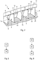
- the auxiliary acoustic device with cavities 7 is integral with said acoustic structure 2, and it comprises a plurality of adjacent chambers (or cavities) 8, separated by adjoining walls 9 (or partitions), as shown in FIG. figure 3 especially.
- Each of the said chambers 8 (closed) is provided with perforations P2 and is able to achieve acoustic absorption.
- the acoustic panel 1 comprises, in addition to the acoustic structure 2, at least one such auxiliary acoustic device with cavities 7.
- the combination of the acoustic structure 2 and the auxiliary cavity acoustic device 7 makes it possible to combine the absorption properties acoustics of the two types of sound absorption, and thus to increase the overall sound absorption of the acoustic panel 1 and to provide acoustic attenuation chambers (or cavities) 8 adapted to noises that are not absorbed by the single structure alveolar 3, as specified below.
- Said acoustic panel 1 and in particular the combination of the acoustic structure 2 and the auxiliary cavity acoustic device 7 may be made in different ways.
- the cavities or chambers 8 of the cavity auxiliary acoustic device 7 can also be produced in different ways.
- the chambers 8 are closed, with the only openings to access the interior of the chamber 8, the perforations P2 (or micro-perforations), as shown in FIGS. figures 2 , 3 and 4 .
- These perforations P2 (or micro-perforations) have reduced surfaces, in particular such that the shape (any) of the perforations P2 can be included in a circle with a diameter of between 0.2 and 0.8 millimeters. Any type of arrangement and shape of these perforations P2 is possible.
- the distribution of the perforations can be carried out in lines and columns on the surface of the wall concerned, with separation distances of two adjacent perforations P2 of 0.1 to 3 millimeters.
- the acoustic structure 2 and the auxiliary cavity acoustic device 7 form a single piece 10.
- the auxiliary acoustic device 7 comprises a so-called front face 11 which preferably corresponds to the extension of the resistive skin 5 (in particular beyond the acoustic structure 2, in particular towards a peripheral edge 21). .
- the front walls 8A of the chambers 8 of the auxiliary cavity acoustic device 7 are part of this front face 11.
- the distribution, the shape, the size and / or the overall surface of the perforations P2 on the face 11 may be, according to the embodiment, identical or different from the distribution, the shape, the size and / or the overall surface of the P1 perforations on the resistive skin 5.
- the auxiliary acoustic device with cavities 7 has a so-called rear face 12 which preferably corresponds to the extension of the rear skin 6.
- the rear walls 8B of the chambers 8 make part of this rear face 12.
- the auxiliary cavity acoustic device 7 is fixed on the acoustic structure 2.
- the auxiliary cavity-type acoustic device 7 comprises a so-called front face 13, which comprises at least a first part 15 devoid of perforations and a second part 14 provided with perforations P2.
- the resistive skin 5 of the acoustic structure 2 is fixed on the second portion 15 (devoid of perforations) of said front face 13, on a band referenced 16 on the figure 4 .
- the auxiliary acoustic device with cavities 7 has a so-called rear face 17 which is fixed on the rear skin 6 of the acoustic structure 8, on a strip referenced 18 on the figure 4 .
- fasteners are possible for fixing the portion 15 of the front face 13 on the resistive skin 5 and / or for fixing the rear face 17 on the rear skin 6.
- These fasteners can be made by gluing or by draping in particular.
- complete draping illustrated by a skin 23 is made from the rear skin 6 on the face 17 and elements 20 and 22 specified below.
- the draping of the structural back skin 6 can be made partially or totally on the chambers.
- the perforations P2 are provided on a front face 11, 13 of the auxiliary acoustic device 7, that is to say on the same side (towards the front) than the P1 perforations of the resistive skin 5 (front skin).
- the front face 11, 13 of the auxiliary acoustic device 7 and the resistive skin 5 are positioned near and preferably close to (or opposite) the source of noise to be attenuated, which makes it possible in particular to increase the effectiveness of sound absorption.
- the acoustic panel 1 comprises at least one auxiliary skin 19 which is arranged between the auxiliary acoustic device 7 and the acoustic structure 2, as shown in FIGS. figures 1 and 4 .
- This auxiliary skin 19 represents a wall of the chambers (or cavities) 8 of the auxiliary acoustic device 7.
- the chambers 8 are thus formed, each, as well in the embodiment of the figure 1 than in that of the figure 4 , partitions 9, a front wall (11 or 13), a rear wall (12 or 17), the auxiliary skin 19 and a wall 20.
- the auxiliary acoustic device 7 can be secured to the acoustic structure 2, at any area of the acoustic structure 2. It is thus possible to provide the auxiliary acoustic device 7 on a part or zone the XY plane of one of the skins, the front skin 5 or the back skin 6.
- the cavity-based auxiliary acoustic device 7 is arranged at least on a portion of at least one peripheral edge 21 of the acoustic structure 2, as shown in FIGS. Figures 1, 2 and 4 .
- the auxiliary acoustic device 7 is arranged on a peripheral edge 21 of the acoustic structure 2, this arrangement, in addition to increasing the absorption capacities and properties, has no or very little impact in terms of space requirement. and at most a low incidence in terms of mass for the acoustic panel 1.
- the peripheral edge 21, the acoustic panel generally comprises an end portion for fixing the acoustic panel 1.
- the auxiliary acoustic cavity device 7 may or may not comprise an end plate 22 for fixing the acoustic panel 1. This end plate 22 may be in the continuity of one of the skins 5 and 6.
- the acoustic panel 1 comprises at least two auxiliary acoustic devices 7 arranged, respectively, on at least two peripheral edges of the acoustic structure 2 or on at least two sections. a peripheral edge of the acoustic structure 2.
- the auxiliary acoustic device 7 comprises identical chambers 8, as shown in FIGS. figures 3 and 5 especially.
- the auxiliary acoustic device 7 comprises chambers 8 of a plurality (two, three, four, ...) of different types, as shown in FIG. figure 7 .
- each chamber type T 8 is configured to allow a preferred acoustic absorption in at least a given acoustic frequency range. Therefore, for two different types T1 and T2 as in the example of the figure 7 , the type T1 chambers 8 achieve a preferred acoustic absorption in a given acoustic frequency range different from that in which the acoustic absorption of T2-type chambers 8 is performed.
- a chamber 8 has acoustic properties enabling it to effectively absorb noise with frequencies belonging to said range of acoustic frequencies considered, and this whether or not it is able to absorb noises having frequencies outside said range.
- each chamber 8 of the auxiliary acoustic device 7 at least the volume of the chamber 8 and the overall surface of all the perforations P2 in the chamber 8 are adapted to give said chamber 8 a preferred acoustic absorption in the acoustic frequency range considered.
- the chambers 8 of different types may be mixed, in particular being distributed relatively uniformly in the acoustic auxiliary device 7.
- This distribution may, for example be alternative, that is to say that, in the case of two different types T1 and T2 of chambers, along a section (in the direction Y) of the acoustic auxiliary device 7 are alternately provided a chamber 8 of type T1, then a chamber 8 of type T2, then a chamber 8 type T1, and so on, as shown in the example of the figure 7 .
- all the parts of the cavity auxiliary acoustic device 7 are configured to absorb the same plurality of acoustic frequency ranges.
- the chambers (or cavities) 8 of the same type may be either grouped together, in at least one zone or a given section of the auxiliary acoustic device. 7, or participate in spacings of different walls 9 creating different volumes, to dampen sources of different noise.
- This second embodiment is particularly advantageous in the presence of different sources of noise, having different frequencies and localized at different locations.
- the acoustic panel 1 is then configured and arranged so that each of these areas is located as close as possible to the source of noise that it must attenuate.
- the acoustic absorption device 7 thus makes it possible to absorb noises having different frequencies, and in particular lower or higher frequencies, than those of the noise or noises absorbed by the acoustic structure 2.
- the combination of the acoustic structure 2 and the auxiliary acoustic device 7 thus makes it possible to combine the properties and characteristics of the two types of sound absorption, and thus to increase the range of noise frequencies that can be attenuated by the acoustic panel 1.
- the auxiliary acoustic device 7 makes it possible to increase the acoustic surface of the acoustic panel 1 .
- the resistive skin 5 (and optionally all or part of the acoustic panel 1) may be flat, as shown in FIGS. Figures 1 to 7 , or be curved (single or double curvature, convex and / or concave).
- the plate 3 can also be made in different ways.
- the material 4 can be an acoustic absorbing material, which participates in the acoustic absorption generated by the acoustic structure 2.
- the material of the plate 3 may be, for example, a carbon fiber-reinforced polymer material of the CFRP ("Carbon Fiber Reinforced Polymer”) type, aramid fiber, fiberglass or metal type such as aluminum or titanium.
- CFRP Carbon Fiber Reinforced Polymer
- the acoustic panel 1 is intended to reduce the noise on a nacelle (not shown) of a propulsion unit (or reactor) of an aircraft.
- the acoustic panel 1 is arranged in the air intake of the propulsion unit.
- the location of the auxiliary acoustic device 7 may play a role in its operation.
- downstream of the airflow close to the blades of the propulsion unit blower
- it makes it possible to reduce the noise directly at the source which also makes it possible to attenuate the other frequencies (because it decreases the overall energy of the sound).
- Upstream it allows to achieve an increased attenuation of the chosen frequency. It can therefore be envisaged to attenuate frequency noise upstream and / or downstream and / or on the circumference.
- the auxiliary acoustic device 7 of the acoustic panel 1 thus makes it possible to reduce specific frequency noises, such as, for example, the frequency of passage of the blades, which presents a strong acoustic emergence.
- the auxiliary acoustic device 7 makes it possible to aim for high and very low frequencies, which is not the case with a honeycomb structure for example. It can thus have a noise reduction of a large volume without having to perform micro-perforations throughout the base.
Landscapes
- Engineering & Computer Science (AREA)
- Chemical & Material Sciences (AREA)
- Combustion & Propulsion (AREA)
- Aviation & Aerospace Engineering (AREA)
- Physics & Mathematics (AREA)
- Acoustics & Sound (AREA)
- Multimedia (AREA)
- Mechanical Engineering (AREA)
- General Engineering & Computer Science (AREA)
- Remote Sensing (AREA)
- Soundproofing, Sound Blocking, And Sound Damping (AREA)
- Building Environments (AREA)
Applications Claiming Priority (1)
| Application Number | Priority Date | Filing Date | Title |
|---|---|---|---|
| FR1853108A FR3079812A1 (fr) | 2018-04-10 | 2018-04-10 | Panneau d'attenuation acoustique pour aeronef presentant des proprietes d'absorption acoustique combinees. |
Publications (2)
| Publication Number | Publication Date |
|---|---|
| EP3552951A1 true EP3552951A1 (de) | 2019-10-16 |
| EP3552951B1 EP3552951B1 (de) | 2024-05-29 |
Family
ID=63014691
Family Applications (1)
| Application Number | Title | Priority Date | Filing Date |
|---|---|---|---|
| EP19167450.6A Active EP3552951B1 (de) | 2018-04-10 | 2019-04-04 | Schalldämmplatte für luftfahrzeug, die kombinierte schallabsorptionseigenschaften aufweist |
Country Status (4)
| Country | Link |
|---|---|
| US (1) | US11459950B2 (de) |
| EP (1) | EP3552951B1 (de) |
| CN (1) | CN110364136B (de) |
| FR (1) | FR3079812A1 (de) |
Cited By (2)
| Publication number | Priority date | Publication date | Assignee | Title |
|---|---|---|---|---|
| FR3129241A1 (fr) | 2021-11-17 | 2023-05-19 | Airbus Operations | Peau poreuse pourvue d’une pluralité de bandes et panneau d’atténuation acoustique comprenant une telle peau poreuse. |
| EP4253031A1 (de) * | 2022-04-01 | 2023-10-04 | Airbus Operations (S.A.S.) | Akustikplatte mit mindestens zwei in einem anderen geschachtelten wabenstrukturen, flugzeug mit mindestens einer solchen akustikplatte |
Families Citing this family (2)
| Publication number | Priority date | Publication date | Assignee | Title |
|---|---|---|---|---|
| US20230167774A1 (en) * | 2021-12-01 | 2023-06-01 | Rohr, Inc. | Attachment ring insulator systems, methods, and assemblies |
| CN115719591A (zh) * | 2022-09-02 | 2023-02-28 | 贵州盘江煤层气开发利用有限责任公司 | 一种复合结构吸声板 |
Citations (6)
| Publication number | Priority date | Publication date | Assignee | Title |
|---|---|---|---|---|
| US4298090A (en) * | 1978-12-27 | 1981-11-03 | Rolls-Royce Limited | Multi-layer acoustic linings |
| WO2008006959A1 (fr) * | 2006-07-12 | 2008-01-17 | Airbus France | Entree d'air pour turbomoteur d'aeronef |
| EP2070816A2 (de) * | 2007-12-12 | 2009-06-17 | The Boeing Company | Verfahren und Vorrichtung für ein integriertes aerodynamisches Paneel |
| FR2954282A1 (fr) * | 2009-12-22 | 2011-06-24 | Airbus Operations Sas | Nacelle incorporant un element de jonction entre une levre et un panneau d'attenuation acoustique |
| WO2011086273A1 (fr) * | 2009-12-22 | 2011-07-21 | Airbus Operations Sas | Panneau pour le traitement acoustique a epaisseur evolutive |
| US9732677B1 (en) * | 2016-05-12 | 2017-08-15 | Rohr, Inc. | Broadband acoustic panels coupled with large secondary cavities to attenuate low frequencies |
Family Cites Families (9)
| Publication number | Priority date | Publication date | Assignee | Title |
|---|---|---|---|---|
| IT1318059B1 (it) * | 2000-06-28 | 2003-07-21 | Aermacchi S P A | Struttura fonoassorbente e di rinforzo per pannelli acustici digondole motore. |
| US7434659B2 (en) * | 2005-04-04 | 2008-10-14 | Hexcel Corporation | Acoustic septum cap honeycomb |
| US7296655B2 (en) * | 2005-04-22 | 2007-11-20 | United Technologies Corporation | Duct liner acoustic splice |
| FR2971613B1 (fr) * | 2011-02-10 | 2013-03-15 | Airbus Operations Sas | Panneau pour le traitement acoustique comprenant une jonction entre deux parties et procede de reparation d'un panneau pour le traitement acoustique |
| FR2980775B1 (fr) * | 2011-10-03 | 2014-07-11 | Airbus Operations Sas | Nacelle d'aeronef comportant un panneau pour le traitement acoustique integrant des canaux d'air chaud et au moins une chambre de stabilisation |
| US8651233B2 (en) * | 2012-05-08 | 2014-02-18 | Hexcel Corporation | Acoustic structure with increased bandwidth suppression |
| US9068345B2 (en) * | 2013-08-12 | 2015-06-30 | Hexcel Corporation | Multi-sectional acoustic septum |
| US9783316B2 (en) * | 2015-06-22 | 2017-10-10 | Rohr, Inc. | Acoustic panel assembly with a folding chamber |
| US9620102B1 (en) * | 2016-05-02 | 2017-04-11 | Hexcel Corporation | Stepped acoustic structures with multiple degrees of freedom |
-
2018
- 2018-04-10 FR FR1853108A patent/FR3079812A1/fr not_active Ceased
-
2019
- 2019-04-04 EP EP19167450.6A patent/EP3552951B1/de active Active
- 2019-04-09 US US16/379,205 patent/US11459950B2/en active Active
- 2019-04-10 CN CN201910284169.7A patent/CN110364136B/zh active Active
Patent Citations (6)
| Publication number | Priority date | Publication date | Assignee | Title |
|---|---|---|---|---|
| US4298090A (en) * | 1978-12-27 | 1981-11-03 | Rolls-Royce Limited | Multi-layer acoustic linings |
| WO2008006959A1 (fr) * | 2006-07-12 | 2008-01-17 | Airbus France | Entree d'air pour turbomoteur d'aeronef |
| EP2070816A2 (de) * | 2007-12-12 | 2009-06-17 | The Boeing Company | Verfahren und Vorrichtung für ein integriertes aerodynamisches Paneel |
| FR2954282A1 (fr) * | 2009-12-22 | 2011-06-24 | Airbus Operations Sas | Nacelle incorporant un element de jonction entre une levre et un panneau d'attenuation acoustique |
| WO2011086273A1 (fr) * | 2009-12-22 | 2011-07-21 | Airbus Operations Sas | Panneau pour le traitement acoustique a epaisseur evolutive |
| US9732677B1 (en) * | 2016-05-12 | 2017-08-15 | Rohr, Inc. | Broadband acoustic panels coupled with large secondary cavities to attenuate low frequencies |
Cited By (6)
| Publication number | Priority date | Publication date | Assignee | Title |
|---|---|---|---|---|
| FR3129241A1 (fr) | 2021-11-17 | 2023-05-19 | Airbus Operations | Peau poreuse pourvue d’une pluralité de bandes et panneau d’atténuation acoustique comprenant une telle peau poreuse. |
| EP4183994A1 (de) | 2021-11-17 | 2023-05-24 | Airbus Operations SAS | Poröse haut mit mehreren bändern und schalldämmplatte mit solch einer porösen haut |
| US12394401B2 (en) | 2021-11-17 | 2025-08-19 | Airbus Operations (Sas) | Porous skin comprising a plurality of strips and an acoustic attenuation panel comprising such a porous skin |
| EP4253031A1 (de) * | 2022-04-01 | 2023-10-04 | Airbus Operations (S.A.S.) | Akustikplatte mit mindestens zwei in einem anderen geschachtelten wabenstrukturen, flugzeug mit mindestens einer solchen akustikplatte |
| FR3134220A1 (fr) * | 2022-04-01 | 2023-10-06 | Airbus Operations (S.A.S.) | Panneau acoustique comprenant au moins deux structures alvéolaires imbriquées l’une dans l’autre, aéronef comportant au moins un tel panneau acoustique |
| US12337984B2 (en) | 2022-04-01 | 2025-06-24 | Airbus Operations Sas | Acoustic panel comprising at least two cellular structures which are nested one inside the other, aircraft having at least one such acoustic panel |
Also Published As
| Publication number | Publication date |
|---|---|
| EP3552951B1 (de) | 2024-05-29 |
| FR3079812A1 (fr) | 2019-10-11 |
| CN110364136A (zh) | 2019-10-22 |
| CN110364136B (zh) | 2024-06-28 |
| US20190309682A1 (en) | 2019-10-10 |
| US11459950B2 (en) | 2022-10-04 |
Similar Documents
| Publication | Publication Date | Title |
|---|---|---|
| EP3489487B1 (de) | Schalldämmplatte für luftfahrzeug | |
| EP3552951B1 (de) | Schalldämmplatte für luftfahrzeug, die kombinierte schallabsorptionseigenschaften aufweist | |
| FR3026122B1 (fr) | Panneau de traitement acoustique | |
| EP3237741B1 (de) | Schalldämpfungsplatte für eine turbostrahltriebwerksgondel | |
| EP2274205B1 (de) | Zwischen dem motor und dem lufteinlass einer flugzeuggondel befindliche wellenabschwächungsarmatur | |
| EP3850616A1 (de) | Schalldämmplatte für ein turbostrahltriebwerk | |
| EP2578842B1 (de) | Triebwerksgondel mit einer Heißluftzuführungsvorrichtung zu einem Paneel, welches sowohl der Geräuschsdämmung als auch dem Schutz vor Vereisung dient | |
| FR3039517A1 (fr) | Structure d’attenuation acoustique a multiples degres d’attenuation pour ensemble propulsif d’aeronef | |
| CA2685287A1 (fr) | Panneau acoustique a caracteristique acoustique variable | |
| WO2021004735A1 (fr) | Revêtement insonorisant comportant une structure alvéolaire | |
| CA2689495A1 (fr) | Revetement pour le traitement acoustique integrant la fonction de traitement du givre avec de l'air chaud | |
| EP2578496A2 (de) | Paneel mit Geräuschsdämmung, welches Heißluftkanäle und mindestens einen Ringkanal umfasst | |
| FR3055662A1 (fr) | Structure interne d'un conduit d'ejection primaire d'une turbomachine comprenant une structure absorbante de sons basses frequences | |
| EP3534360B1 (de) | Schalldämmende beschichtung, die eine wabenstruktur mit gekrümmten zellen umfasst, die auf der einen und der anderen seite aus derselben innenwand gebildet werden | |
| WO2022129778A1 (fr) | Panneau de traitement acoustique à encombrement réduit pour turboréacteur | |
| CA2803746A1 (fr) | Panneau acoustique pour nacelle de turboreacteur avec moyens de fixation integres | |
| FR3088905A1 (fr) | Structure d’absorption acoustique comprenant un système de drainage de liquide et ensemble propulsif comportant une telle structure d’absorption acoustique | |
| FR3101723A1 (fr) | Panneau d’atténuation acoustique pour onde basses fréquences | |
| WO2022263751A1 (fr) | Panneau de traitement acoustique renforcé pour un ensemble propulsif d'aeronef | |
| FR2962586A1 (fr) | Panneau pour le traitement acoustique | |
| WO2009115700A1 (fr) | Panneau acoustique d'une nacelle d'un aerone | |
| EP3724076B1 (de) | Lufteinlasslippe für eine turbostrahlgondel | |
| FR3072365A1 (fr) | Attenuation acoustique sur une paroi de turbomachine | |
| EP4687137A1 (de) | Schallabsorbierende struktur mit unterteilten zellen, die mehrere arten von resonatoren kombiniert | |
| FR3164049A1 (fr) | Dispositif d’isolation acoustique pour un aéronef |
Legal Events
| Date | Code | Title | Description |
|---|---|---|---|
| PUAI | Public reference made under article 153(3) epc to a published international application that has entered the european phase |
Free format text: ORIGINAL CODE: 0009012 |
|
| STAA | Information on the status of an ep patent application or granted ep patent |
Free format text: STATUS: THE APPLICATION HAS BEEN PUBLISHED |
|
| AK | Designated contracting states |
Kind code of ref document: A1 Designated state(s): AL AT BE BG CH CY CZ DE DK EE ES FI FR GB GR HR HU IE IS IT LI LT LU LV MC MK MT NL NO PL PT RO RS SE SI SK SM TR |
|
| AX | Request for extension of the european patent |
Extension state: BA ME |
|
| STAA | Information on the status of an ep patent application or granted ep patent |
Free format text: STATUS: REQUEST FOR EXAMINATION WAS MADE |
|
| 17P | Request for examination filed |
Effective date: 20200410 |
|
| RBV | Designated contracting states (corrected) |
Designated state(s): AL AT BE BG CH CY CZ DE DK EE ES FI FR GB GR HR HU IE IS IT LI LT LU LV MC MK MT NL NO PL PT RO RS SE SI SK SM TR |
|
| STAA | Information on the status of an ep patent application or granted ep patent |
Free format text: STATUS: EXAMINATION IS IN PROGRESS |
|
| 17Q | First examination report despatched |
Effective date: 20210217 |
|
| REG | Reference to a national code |
Ref legal event code: R079 Ipc: B64D0033020000 Ref country code: DE Ref legal event code: R079 Ref document number: 602019052829 Country of ref document: DE Free format text: PREVIOUS MAIN CLASS: B64C0001400000 Ipc: B64D0033020000 |
|
| GRAP | Despatch of communication of intention to grant a patent |
Free format text: ORIGINAL CODE: EPIDOSNIGR1 |
|
| STAA | Information on the status of an ep patent application or granted ep patent |
Free format text: STATUS: GRANT OF PATENT IS INTENDED |
|
| RIC1 | Information provided on ipc code assigned before grant |
Ipc: B64D 33/02 20060101AFI20231208BHEP |
|
| INTG | Intention to grant announced |
Effective date: 20240104 |
|
| GRAS | Grant fee paid |
Free format text: ORIGINAL CODE: EPIDOSNIGR3 |
|
| GRAA | (expected) grant |
Free format text: ORIGINAL CODE: 0009210 |
|
| STAA | Information on the status of an ep patent application or granted ep patent |
Free format text: STATUS: THE PATENT HAS BEEN GRANTED |
|
| AK | Designated contracting states |
Kind code of ref document: B1 Designated state(s): AL AT BE BG CH CY CZ DE DK EE ES FI FR GB GR HR HU IE IS IT LI LT LU LV MC MK MT NL NO PL PT RO RS SE SI SK SM TR |
|
| REG | Reference to a national code |
Ref country code: CH Ref legal event code: EP |
|
| REG | Reference to a national code |
Ref country code: IE Ref legal event code: FG4D Free format text: LANGUAGE OF EP DOCUMENT: FRENCH |
|
| REG | Reference to a national code |
Ref country code: DE Ref legal event code: R096 Ref document number: 602019052829 Country of ref document: DE |
|
| REG | Reference to a national code |
Ref country code: LT Ref legal event code: MG9D |
|
| REG | Reference to a national code |
Ref country code: NL Ref legal event code: MP Effective date: 20240529 |
|
| PG25 | Lapsed in a contracting state [announced via postgrant information from national office to epo] |
Ref country code: IS Free format text: LAPSE BECAUSE OF FAILURE TO SUBMIT A TRANSLATION OF THE DESCRIPTION OR TO PAY THE FEE WITHIN THE PRESCRIBED TIME-LIMIT Effective date: 20240929 |
|
| PG25 | Lapsed in a contracting state [announced via postgrant information from national office to epo] |
Ref country code: BG Free format text: LAPSE BECAUSE OF FAILURE TO SUBMIT A TRANSLATION OF THE DESCRIPTION OR TO PAY THE FEE WITHIN THE PRESCRIBED TIME-LIMIT Effective date: 20240529 |
|
| PG25 | Lapsed in a contracting state [announced via postgrant information from national office to epo] |
Ref country code: HR Free format text: LAPSE BECAUSE OF FAILURE TO SUBMIT A TRANSLATION OF THE DESCRIPTION OR TO PAY THE FEE WITHIN THE PRESCRIBED TIME-LIMIT Effective date: 20240529 Ref country code: FI Free format text: LAPSE BECAUSE OF FAILURE TO SUBMIT A TRANSLATION OF THE DESCRIPTION OR TO PAY THE FEE WITHIN THE PRESCRIBED TIME-LIMIT Effective date: 20240529 |
|
| PG25 | Lapsed in a contracting state [announced via postgrant information from national office to epo] |
Ref country code: GR Free format text: LAPSE BECAUSE OF FAILURE TO SUBMIT A TRANSLATION OF THE DESCRIPTION OR TO PAY THE FEE WITHIN THE PRESCRIBED TIME-LIMIT Effective date: 20240830 |
|
| REG | Reference to a national code |
Ref country code: AT Ref legal event code: MK05 Ref document number: 1690443 Country of ref document: AT Kind code of ref document: T Effective date: 20240529 |
|
| PG25 | Lapsed in a contracting state [announced via postgrant information from national office to epo] |
Ref country code: ES Free format text: LAPSE BECAUSE OF FAILURE TO SUBMIT A TRANSLATION OF THE DESCRIPTION OR TO PAY THE FEE WITHIN THE PRESCRIBED TIME-LIMIT Effective date: 20240529 |
|
| PG25 | Lapsed in a contracting state [announced via postgrant information from national office to epo] |
Ref country code: AT Free format text: LAPSE BECAUSE OF FAILURE TO SUBMIT A TRANSLATION OF THE DESCRIPTION OR TO PAY THE FEE WITHIN THE PRESCRIBED TIME-LIMIT Effective date: 20240529 |
|
| PG25 | Lapsed in a contracting state [announced via postgrant information from national office to epo] |
Ref country code: PL Free format text: LAPSE BECAUSE OF FAILURE TO SUBMIT A TRANSLATION OF THE DESCRIPTION OR TO PAY THE FEE WITHIN THE PRESCRIBED TIME-LIMIT Effective date: 20240529 |
|
| PG25 | Lapsed in a contracting state [announced via postgrant information from national office to epo] |
Ref country code: LV Free format text: LAPSE BECAUSE OF FAILURE TO SUBMIT A TRANSLATION OF THE DESCRIPTION OR TO PAY THE FEE WITHIN THE PRESCRIBED TIME-LIMIT Effective date: 20240529 |
|
| PG25 | Lapsed in a contracting state [announced via postgrant information from national office to epo] |
Ref country code: PL Free format text: LAPSE BECAUSE OF FAILURE TO SUBMIT A TRANSLATION OF THE DESCRIPTION OR TO PAY THE FEE WITHIN THE PRESCRIBED TIME-LIMIT Effective date: 20240529 Ref country code: NO Free format text: LAPSE BECAUSE OF FAILURE TO SUBMIT A TRANSLATION OF THE DESCRIPTION OR TO PAY THE FEE WITHIN THE PRESCRIBED TIME-LIMIT Effective date: 20240829 Ref country code: LV Free format text: LAPSE BECAUSE OF FAILURE TO SUBMIT A TRANSLATION OF THE DESCRIPTION OR TO PAY THE FEE WITHIN THE PRESCRIBED TIME-LIMIT Effective date: 20240529 Ref country code: IS Free format text: LAPSE BECAUSE OF FAILURE TO SUBMIT A TRANSLATION OF THE DESCRIPTION OR TO PAY THE FEE WITHIN THE PRESCRIBED TIME-LIMIT Effective date: 20240929 Ref country code: HR Free format text: LAPSE BECAUSE OF FAILURE TO SUBMIT A TRANSLATION OF THE DESCRIPTION OR TO PAY THE FEE WITHIN THE PRESCRIBED TIME-LIMIT Effective date: 20240529 Ref country code: GR Free format text: LAPSE BECAUSE OF FAILURE TO SUBMIT A TRANSLATION OF THE DESCRIPTION OR TO PAY THE FEE WITHIN THE PRESCRIBED TIME-LIMIT Effective date: 20240830 Ref country code: FI Free format text: LAPSE BECAUSE OF FAILURE TO SUBMIT A TRANSLATION OF THE DESCRIPTION OR TO PAY THE FEE WITHIN THE PRESCRIBED TIME-LIMIT Effective date: 20240529 Ref country code: ES Free format text: LAPSE BECAUSE OF FAILURE TO SUBMIT A TRANSLATION OF THE DESCRIPTION OR TO PAY THE FEE WITHIN THE PRESCRIBED TIME-LIMIT Effective date: 20240529 Ref country code: BG Free format text: LAPSE BECAUSE OF FAILURE TO SUBMIT A TRANSLATION OF THE DESCRIPTION OR TO PAY THE FEE WITHIN THE PRESCRIBED TIME-LIMIT Effective date: 20240529 Ref country code: AT Free format text: LAPSE BECAUSE OF FAILURE TO SUBMIT A TRANSLATION OF THE DESCRIPTION OR TO PAY THE FEE WITHIN THE PRESCRIBED TIME-LIMIT Effective date: 20240529 Ref country code: RS Free format text: LAPSE BECAUSE OF FAILURE TO SUBMIT A TRANSLATION OF THE DESCRIPTION OR TO PAY THE FEE WITHIN THE PRESCRIBED TIME-LIMIT Effective date: 20240829 |
|
| PG25 | Lapsed in a contracting state [announced via postgrant information from national office to epo] |
Ref country code: NL Free format text: LAPSE BECAUSE OF FAILURE TO SUBMIT A TRANSLATION OF THE DESCRIPTION OR TO PAY THE FEE WITHIN THE PRESCRIBED TIME-LIMIT Effective date: 20240529 |
|
| PG25 | Lapsed in a contracting state [announced via postgrant information from national office to epo] |
Ref country code: NL Free format text: LAPSE BECAUSE OF FAILURE TO SUBMIT A TRANSLATION OF THE DESCRIPTION OR TO PAY THE FEE WITHIN THE PRESCRIBED TIME-LIMIT Effective date: 20240529 |
|
| PG25 | Lapsed in a contracting state [announced via postgrant information from national office to epo] |
Ref country code: DK Free format text: LAPSE BECAUSE OF FAILURE TO SUBMIT A TRANSLATION OF THE DESCRIPTION OR TO PAY THE FEE WITHIN THE PRESCRIBED TIME-LIMIT Effective date: 20240529 |
|
| PG25 | Lapsed in a contracting state [announced via postgrant information from national office to epo] |
Ref country code: EE Free format text: LAPSE BECAUSE OF FAILURE TO SUBMIT A TRANSLATION OF THE DESCRIPTION OR TO PAY THE FEE WITHIN THE PRESCRIBED TIME-LIMIT Effective date: 20240529 |
|
| PG25 | Lapsed in a contracting state [announced via postgrant information from national office to epo] |
Ref country code: CZ Free format text: LAPSE BECAUSE OF FAILURE TO SUBMIT A TRANSLATION OF THE DESCRIPTION OR TO PAY THE FEE WITHIN THE PRESCRIBED TIME-LIMIT Effective date: 20240529 |
|
| PG25 | Lapsed in a contracting state [announced via postgrant information from national office to epo] |
Ref country code: RO Free format text: LAPSE BECAUSE OF FAILURE TO SUBMIT A TRANSLATION OF THE DESCRIPTION OR TO PAY THE FEE WITHIN THE PRESCRIBED TIME-LIMIT Effective date: 20240529 Ref country code: SK Free format text: LAPSE BECAUSE OF FAILURE TO SUBMIT A TRANSLATION OF THE DESCRIPTION OR TO PAY THE FEE WITHIN THE PRESCRIBED TIME-LIMIT Effective date: 20240529 |
|
| PG25 | Lapsed in a contracting state [announced via postgrant information from national office to epo] |
Ref country code: SM Free format text: LAPSE BECAUSE OF FAILURE TO SUBMIT A TRANSLATION OF THE DESCRIPTION OR TO PAY THE FEE WITHIN THE PRESCRIBED TIME-LIMIT Effective date: 20240529 |
|
| PG25 | Lapsed in a contracting state [announced via postgrant information from national office to epo] |
Ref country code: SM Free format text: LAPSE BECAUSE OF FAILURE TO SUBMIT A TRANSLATION OF THE DESCRIPTION OR TO PAY THE FEE WITHIN THE PRESCRIBED TIME-LIMIT Effective date: 20240529 Ref country code: SK Free format text: LAPSE BECAUSE OF FAILURE TO SUBMIT A TRANSLATION OF THE DESCRIPTION OR TO PAY THE FEE WITHIN THE PRESCRIBED TIME-LIMIT Effective date: 20240529 Ref country code: RO Free format text: LAPSE BECAUSE OF FAILURE TO SUBMIT A TRANSLATION OF THE DESCRIPTION OR TO PAY THE FEE WITHIN THE PRESCRIBED TIME-LIMIT Effective date: 20240529 Ref country code: EE Free format text: LAPSE BECAUSE OF FAILURE TO SUBMIT A TRANSLATION OF THE DESCRIPTION OR TO PAY THE FEE WITHIN THE PRESCRIBED TIME-LIMIT Effective date: 20240529 Ref country code: DK Free format text: LAPSE BECAUSE OF FAILURE TO SUBMIT A TRANSLATION OF THE DESCRIPTION OR TO PAY THE FEE WITHIN THE PRESCRIBED TIME-LIMIT Effective date: 20240529 Ref country code: CZ Free format text: LAPSE BECAUSE OF FAILURE TO SUBMIT A TRANSLATION OF THE DESCRIPTION OR TO PAY THE FEE WITHIN THE PRESCRIBED TIME-LIMIT Effective date: 20240529 |
|
| PG25 | Lapsed in a contracting state [announced via postgrant information from national office to epo] |
Ref country code: IT Free format text: LAPSE BECAUSE OF FAILURE TO SUBMIT A TRANSLATION OF THE DESCRIPTION OR TO PAY THE FEE WITHIN THE PRESCRIBED TIME-LIMIT Effective date: 20240529 |
|
| REG | Reference to a national code |
Ref country code: DE Ref legal event code: R097 Ref document number: 602019052829 Country of ref document: DE |
|
| PLBE | No opposition filed within time limit |
Free format text: ORIGINAL CODE: 0009261 |
|
| STAA | Information on the status of an ep patent application or granted ep patent |
Free format text: STATUS: NO OPPOSITION FILED WITHIN TIME LIMIT |
|
| PG25 | Lapsed in a contracting state [announced via postgrant information from national office to epo] |
Ref country code: SI Free format text: LAPSE BECAUSE OF FAILURE TO SUBMIT A TRANSLATION OF THE DESCRIPTION OR TO PAY THE FEE WITHIN THE PRESCRIBED TIME-LIMIT Effective date: 20240529 |
|
| 26N | No opposition filed |
Effective date: 20250303 |
|
| PGFP | Annual fee paid to national office [announced via postgrant information from national office to epo] |
Ref country code: DE Payment date: 20250422 Year of fee payment: 7 |
|
| PGFP | Annual fee paid to national office [announced via postgrant information from national office to epo] |
Ref country code: GB Payment date: 20250423 Year of fee payment: 7 |
|
| PGFP | Annual fee paid to national office [announced via postgrant information from national office to epo] |
Ref country code: FR Payment date: 20250425 Year of fee payment: 7 |
|
| PG25 | Lapsed in a contracting state [announced via postgrant information from national office to epo] |
Ref country code: SE Free format text: LAPSE BECAUSE OF FAILURE TO SUBMIT A TRANSLATION OF THE DESCRIPTION OR TO PAY THE FEE WITHIN THE PRESCRIBED TIME-LIMIT Effective date: 20240529 |
|
| REG | Reference to a national code |
Ref country code: CH Ref legal event code: H13 Free format text: ST27 STATUS EVENT CODE: U-0-0-H10-H13 (AS PROVIDED BY THE NATIONAL OFFICE) Effective date: 20251125 |
|
| PG25 | Lapsed in a contracting state [announced via postgrant information from national office to epo] |
Ref country code: LU Free format text: LAPSE BECAUSE OF NON-PAYMENT OF DUE FEES Effective date: 20250404 |
|
| PG25 | Lapsed in a contracting state [announced via postgrant information from national office to epo] |
Ref country code: MC Free format text: LAPSE BECAUSE OF FAILURE TO SUBMIT A TRANSLATION OF THE DESCRIPTION OR TO PAY THE FEE WITHIN THE PRESCRIBED TIME-LIMIT Effective date: 20240529 |
|
| REG | Reference to a national code |
Ref country code: BE Ref legal event code: MM Effective date: 20250430 |
|
| PG25 | Lapsed in a contracting state [announced via postgrant information from national office to epo] |
Ref country code: BE Free format text: LAPSE BECAUSE OF NON-PAYMENT OF DUE FEES Effective date: 20250430 |
|
| PG25 | Lapsed in a contracting state [announced via postgrant information from national office to epo] |
Ref country code: CH Free format text: LAPSE BECAUSE OF NON-PAYMENT OF DUE FEES Effective date: 20250430 |
|
| PG25 | Lapsed in a contracting state [announced via postgrant information from national office to epo] |
Ref country code: IE Free format text: LAPSE BECAUSE OF NON-PAYMENT OF DUE FEES Effective date: 20250404 |