EP3552978A1 - Anlage und verfahren zum legen von flaschen in entgegengesetzter anordnung - Google Patents
Anlage und verfahren zum legen von flaschen in entgegengesetzter anordnung Download PDFInfo
- Publication number
- EP3552978A1 EP3552978A1 EP19167965.3A EP19167965A EP3552978A1 EP 3552978 A1 EP3552978 A1 EP 3552978A1 EP 19167965 A EP19167965 A EP 19167965A EP 3552978 A1 EP3552978 A1 EP 3552978A1
- Authority
- EP
- European Patent Office
- Prior art keywords
- bottle
- bottles
- bêche
- tête
- laying
- Prior art date
- Legal status (The legal status is an assumption and is not a legal conclusion. Google has not performed a legal analysis and makes no representation as to the accuracy of the status listed.)
- Granted
Links
Images


Classifications
-
- B—PERFORMING OPERATIONS; TRANSPORTING
- B65—CONVEYING; PACKING; STORING; HANDLING THIN OR FILAMENTARY MATERIAL
- B65B—MACHINES, APPARATUS OR DEVICES FOR, OR METHODS OF, PACKAGING ARTICLES OR MATERIALS; UNPACKING
- B65B21/00—Packaging or unpacking of bottles
- B65B21/02—Packaging or unpacking of bottles in or from preformed containers, e.g. crates
- B65B21/025—Packaging or unpacking of bottles in or from preformed containers, e.g. crates the bottles being arranged in a head-to-bottom formation
-
- B—PERFORMING OPERATIONS; TRANSPORTING
- B65—CONVEYING; PACKING; STORING; HANDLING THIN OR FILAMENTARY MATERIAL
- B65B—MACHINES, APPARATUS OR DEVICES FOR, OR METHODS OF, PACKAGING ARTICLES OR MATERIALS; UNPACKING
- B65B21/00—Packaging or unpacking of bottles
- B65B21/02—Packaging or unpacking of bottles in or from preformed containers, e.g. crates
- B65B21/14—Introducing or removing groups of bottles, for filling or emptying containers in one operation
- B65B21/18—Introducing or removing groups of bottles, for filling or emptying containers in one operation using grippers engaging bottles, e.g. bottle necks
- B65B21/20—Introducing or removing groups of bottles, for filling or emptying containers in one operation using grippers engaging bottles, e.g. bottle necks with means for varying spacing of bottles
-
- B—PERFORMING OPERATIONS; TRANSPORTING
- B65—CONVEYING; PACKING; STORING; HANDLING THIN OR FILAMENTARY MATERIAL
- B65B—MACHINES, APPARATUS OR DEVICES FOR, OR METHODS OF, PACKAGING ARTICLES OR MATERIALS; UNPACKING
- B65B35/00—Supplying, feeding, arranging or orientating articles to be packaged
- B65B35/56—Orientating, i.e. changing the attitude of, articles, e.g. of non-uniform cross-section
- B65B35/58—Turning articles by positively-acting means, e.g. to present labelled portions in uppermost position
-
- B—PERFORMING OPERATIONS; TRANSPORTING
- B65—CONVEYING; PACKING; STORING; HANDLING THIN OR FILAMENTARY MATERIAL
- B65B—MACHINES, APPARATUS OR DEVICES FOR, OR METHODS OF, PACKAGING ARTICLES OR MATERIALS; UNPACKING
- B65B59/00—Arrangements to enable machines to handle articles of different sizes, to produce packages of different sizes, to vary the contents of packages, to handle different types of packaging material, or to give access for cleaning or maintenance purposes
- B65B59/001—Arrangements to enable adjustments related to the product to be packaged
Definitions
- the object of the present invention is a plant and a method for laying bottles in ativ-bêche (head-to-tail) arrangement.
- Bottom means in particular a container for liquids, mostly made of glass, of any shape, in particular of a cylindrical shape which narrows upwards into the so-called neck.
- plant for laying bottles in aroy-bêche arrangement means a plant suitable to lay bottles within a container.
- a container may be destined for packing bottles, and be constituted for example by a box or crate, or be a container for the temporary storage of bottles, intended to be subsequently transferred.
- the plant and the method according to the invention are applicable to laying bottles containing wine or sparkling wine, but may be applied to laying bottles containing any type of liquid, food and non-food.
- a “tête-bêche” (head-to-tail) arrangement is generally understood to mean the arrangement of two things of the same kind, so that the upper part of one is facing or alongside the lower part of the other.
- arranging bottles in a “tête-bêche” manner means arranging the bottles side by side to each other horizontally, alternately reversing the neck-bottom orientation, as shown in Figure 1 where some bottles B are shown arranged inside a box S.
- laying systems with a gripper device mounted on a Cartesian axis movement structure are used.
- a movable gripper device is in turn equipped with a plurality of mechanical clamps suitable to grip the bottles by the neck. These mechanical clamps, placed side by side to each other, are rotatable in parallel planes.
- the movable gripper device is carried on a bottle conveyor line to receive the bottles in a vertical position.
- Each mechanical clamp grips a bottle arranged vertically by the neck.
- the movable gripper device lifts the mechanical clamp with the attached bottles. During lifting, each mechanical clamp is rotated so that the relative bottle is brought into a horizontal position.
- Each clamp is configured to impart on the relative bottle a movement of rotation in the direction opposite to the adjacent clamps.
- the bottles are arranged horizontally in ativ-bêche arrangement.
- the movable gripper device may transport the bottles in a laying line into containers and lay in one or more containers (e.g. boxes/packing crates) the bottles already in thetiv-bêche arrangement.
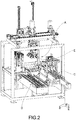
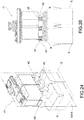
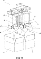
- FIG. 2 An example of a bottle laying plant described above is shown in Figure 2 , where A indicates the movable gripper device, E the single, orientable mechanical clamp, C the bottle transport line and D the line for laying in containers.
- a first limitation is linked to the constructive complexity of the movable gripper device.
- Such device must, in effect, be able to carry out all the steps of handling and laying the bottles: from gripping the bottles to laying them in the box.
- Such mechanical complexity increases the cost and weight of the same movable device.
- each movable gripper device is configured to act specifically on only one specific bottle format.
- One of the main parameters that identify a bottle format for the purpose of handling a bottle is the cross section of the bottle body, identifiable by its maximum dimension, which in particular corresponds to the maximum bottle diameter in the case of a substantially circular cross section.
- the fact that the movable gripper device is configured for a specific bottle format has a negative effect on the operative flexibility of the laying plant. In effect, when changing the bottle format, it is necessary to replace the movable gripper device, resulting in machine stops and operator interventions.
- the creation of a gripper device capable of adapting to bottle format changes would, in effect, impart further constructive complications, which would be excessively onerous in terms of increasing the cost and weight of the movable device.
- the weight of the gripper device complicates replacement operations if this becomes necessary, for example, for changing the bottle format or for maintenance.
- the use of the aforesaid gripper device extends the operating cycle times of the laying plant.
- the laying plant remains in effect in stand-by during the execution of each single cycle of operations of gripping, rotating and laying the bottles. This leads to the introduction of long downtimes.
- the object of the present invention is to eliminate all or part of the drawbacks of the prior art mentioned above, by providing a plant for laying bottles in ativ-bêche arrangement which allows bottle format changes to be flexibly managed, significantly reducing the need to replace the movable gripper device, without however leading to an increase in the mechanical complexity of the movable gripper device.
- a further object of the present invention is to provide a plant for laying bottles in ativ-bêche arrangement that is easily manageable from an operative point of view.
- a further object of the present invention is to provide a plant for laying bottles in ativ-bêche arrangement that is simple and economical to implement.
- the plant 1 for laying bottles in ativ-bêche arrangement according to the invention is generally suitable to lay bottles inside a container.
- a container may be destined for packing bottles, and be constituted for example by a box or crate, or be a container for the temporary storage of bottles, intended to be subsequently transferred.
- the plant for laying bottles in ativ-bêche arrangement 1 comprises:
- the bottle positioning system 30 is structurally and functionally distinct from the bottle transferring device 40.
- the movable device for gripping bottles present in the solutions of the prior art has been divided into two distinct systems/devices, i.e. the bottle positioning system 30 and the bottle transferring device 40.
- the bottle handling operations necessary to lay the bottles in ativ-bêche configuration are completely separate and distinct from the operations of transferring the bottles into the laying line. Handling operations and transfer operations are in effect carried out by operatively separate and autonomous systems/devices.
- the bottle positioning system 30 may thus be structured and sized in such a way as to carry out only the operations aimed at laying the bottles in aroy-bêche configuration, since the execution of the operations of transferring these bottles to the laying line 20 is completely entrusted to the bottle transferring device 40.
- the bottle transferring device 40 may be structured and sized in such a way as to perform only the operations of transferring bottles (already in thenius-bêche configuration) to the laying line 20, since the execution of the operations aimed at laying bottles in the27-bêche configuration is completely entrusted to the aforementioned positioning system 30.
- a first advantage of such an operative separation is that it is possible to simplify the mechanical structure of the bottle transferring device 40, since it is no longer required for this device to impart the relative rotation movements among the bottles handled thereby.
- the bottle transferring device 40 is called to engage in gripping groups of bottles already arranged in thenius-bêche configuration. Once the bottles have been engaged, the bottle transferring device 40 may be limited to transferring them in bulk to the laying line 20 in containers. At most, the transfer device 40 may be configured to separate (divide) two distinct groups of bottles by means of a simple relative movement of translation.
- the transfer device 40 does not have to impart relative rotation movements among the bottles, it is possible to structure this device 40 in such a way that it may be adapted to different bottle formats (in particular, according to the maximum size/diameter of the bottle), for example by equipping it with means suitable to vary the distance provided between the components for gripping the bottles. It is also possible to use - as bottle grippers - vacuum suction cups instead of more complex mechanical clamps.
- the bottle transferring device 40 is not required to change the relative orientation of the bottles in order to lay them in ativ-bêche configuration, but rather only to transfer bottles already arranged in this configuration from one point of the plant 1 to another, it is possible to significantly simplify the relative support and movement structure.
- a support and movement structure it is possible to adopt a robotic arm, instead of a more cumbersome system of Cartesian axes.
- a second advantage of the aforesaid operative separation is that it is also possible to simplify the mechanical structure of the system 30 for positioning bottles in ativ-bêche configuration.
- the bottle positioning system 30 is no longer required to orient bottles in ativ-bêche configuration operating suspended in the air and in movement, but rather it may carry out such manipulations operating in a "static" configuration, i.e. without requiring the system 30 as a whole to move with respect to the relative support structure.
- This makes it possible to structure this system 30 in such a way that it may be adapted to different bottle formats, for example by equipping it with means suitable to vary the distance provided between the components for handling the bottles.
- the fact that the handling of the bottles in thetiv-bêche configuration is not linked to transferring also makes it possible to use - as bottle gripping elements - vacuum suction cups instead of more complex mechanical clamps.
- the laying plant 1 may be structured to flexibly manage bottle format changes, significantly reducing the need to replace the movable device for gripping and handling bottles, without, however, increasing the mechanical complexity of the bottle transferring device.
- a third advantage of the aforesaid operative separation is that it is possible to reduce downtime in the operative cycle of the laying plant. In effect, as will be explained below, the operations of positioning bottles intiv-bêche configuration may continue even at the same time as transferring bottles into the laying line.
- the line 20 for laying in containers is suitable for presenting in sequence the containers within which the bottles are to be laid in aroy-bêche arrangement.
- the containers may be packing containers (such as boxes or crates) or temporary containers.
- the laying line 20 in the plant 1 may be completely traditional and is therefore well known to a person skilled in the art. It will therefore not be described in detail.
- the line 20 for laying in containers has been illustrated as a bottle packaging line. This illustration should be understood as purely illustrative and non-limiting.
- the aforesaid system 30 for positioning bottles in ativ-bêche configuration is associated to the device 10 for receiving bottles.
- the aforesaid bottle transferring device 40 comprises:
- the aforesaid movement means consist of a robotic arm 45.
- the aforesaid movement means are made up of a system of Cartesian axes.
- the aforesaid system 30 for positioning bottles in ativ-bêche configuration may be structurally integrated into the bottle receiving device 10.
- the bottle positioning system 30 since it does not perform the function of transferring bottles to the laying line - does not require a dedicated support structure, which is sized to withstand the vibrations and stresses generated by the movement of large weights suspended in the air. Therefore, the bottle positioning system 30 may use the support structure of other parts of the plant, in particular of the bottle receiving device 10.
- this support structure may be constituted by a support frame (such as a framework with a plurality of support legs on the ground) that defines a horizontal support surface on the top thereof.
- a support frame such as a framework with a plurality of support legs on the ground
- the aforesaid device 10 for receiving bottles comprises:
- the aforesaid system 30 for positioning bottles in thet-bêche configuration is positioned in the free space 17 between the aforesaid two bottle storage lanes 11, 12 and is suitable to act on bottles in said two storage lanes 11, 12.
- the bottles arrive in the proximity of the positioning system 30, already arranged so as to be able to be picked up. This avoids therefore the need to move the bottle positioning system towards the bottles.
- the bottle receiving device 10 comprises upstream of the diverter 13 a conveyor belt 14 (or another equivalent device) suitable to impart on the bottles a translational movement along the aforesaid feed direction X from an inlet portion 15 to the diverter 13.
- the aforesaid bottle receiving device 10 is fed by a traditional bottle transport line (not illustrated) that connects the laying plant 1 to a bottling plant (not illustrated).
- the bottle receiving device 10 it is possible to define a center line M-M, substantially parallel to or corresponding to the bottle feed direction X set by the aforesaid conveyor belt 1.
- the two bottle storage lanes 11 and 12 extend parallel to this bottle feed direction X on opposite sides relative to this center line M-M so as to define the aforesaid free space 17, wherein is arranged the aforesaid bottle positioning system 30.
- each bottle storage lane 11 and 12 is supported by a longitudinal appendage 11a and 12a of a main support structure 14a of the conveyor belt 14.
- each storage lane 11, 12 is equipped on the outside with a longitudinal bottle containment barrier 11b, 12b, while there are no barriers on the inside facing the free space 17, to allow the bottle positioning system 30 to freely access the bottles stored therein.
- each storage lane 11, 12 is equipped with limit stop means 16, which are suitable to limit the bottle storage area within a predefined longitudinal segment of the lane.
- limit stop means 16 are adjustable.
- the longitudinal extension of the bottle storage area is chosen according to how much the operating area of intervention of the bottle positioning system 30 extends longitudinally within the aforesaid free space 17.
- the bottles B moved by the conveyor belt 14 reach the diverter 13 which directs them by sorting them into the two storage lanes 11, 12.
- the bottles move along the storage lanes 11, 12 by the pushing imparted by the bottles that progressively enter the lanes.
- the storage lanes 11, 12 are equipped with a smooth bottom (to avoid friction) or rollers.
- the diverter 13 is defined by:
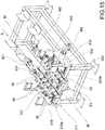
- the aforesaid system 30 for positioning bottles in ativ-bêche configuration comprises a plurality of bottle handling devices 31, 32.
- Each bottle handling device 31, 32 is suitable to pick up a single bottle vertically from one of the two storage lanes 11, 12 of the bottle receiving device 10 (see figures 5 to 8 ) and position it horizontally in the space between the two storage lanes 11, 12 with the bottom-neck extension axis Y arranged transversely to the aforesaid bottle feed direction X and with neck-bottom orientation reversed relative to the orientation received by the bottles positioned by the two handling devices 32 adjacent thereto (see figures 9 to 11 ).
- the set of aforesaid handling devices 31, 32 arranges horizontally one or more groups of bottles placed side by side to each other in ativ-bêche configuration.
- the aforesaid handling devices 31, 32 are organized into two distinct operating groups.
- the handling devices 31 of a first group are suitable to take bottles from a first 11 of the aforesaid two storage lanes 11 and lay them horizontally with a first neck-bottom orientation
- the handling devices 32 of a second group are suitable to take bottles from the other storage lane 12 and lay them horizontally with a second neck-bottom orientation, inverted relative to the first.
- the handling devices 31, 32 of the two operating groups are arranged in alternating sequence in a direction parallel to the aforesaid bottle feed direction X.
- each handling device 31, 32 may be positioned adjustably relative to the other handling devices 31, 32 in the longitudinal direction (parallel to the feed direction X) and/or in the transverse direction (orthogonally to the feed direction X) relative to the feed direction X in order to adapt the positioning of the bottles int-bêche configuration to the different formats of the bottles that may be handled by the plant 1.
- each handling device 31, 32 is movable transversely relative to the feed direction X in order to adjust the gripping distance on the bottles B arranged in the relative storage lane 11, 12.
- the handling devices 31 or 32 belonging to the same operating group are movable all together transversely.
- the aforesaid handling devices 31 and 32 are aligned on two separate rows F1 and F2, parallel to the aforesaid feed direction X, one for each operating group.
- the number of handling devices 31 and 32 in each row F1 and F2 may be chosen at the design stage according to the working time of the plant 1.
- the handling devices 31 and 32 may be divided into modular sets, which are arranged in series along the feed axis X and are suitable to act on the bottles present in the two storage lanes independently.
- Each modular set comprises handling devices arranged on the two rows F1 and F2, and therefore suitable to act on both storage lanes 11, 12.
- each support frame 310a, 320a may be constituted by a carriage which is guided slidably by guides 340 arranged transversely to the feed direction X.
- the handling devices 31 or 32 in each row are kinematically associated to a worm screw 310 or 320, which is in turn associated to the respective support frame 310a or 320a and extends parallel to said feed direction X.
- the rotation of the worm screw 310 or 320 determines the axial sliding of the devices 31 or 32 associated thereto and thus their axial distribution along the worm screw 310 or 320, so as to vary the axial (longitudinal) pitch of the bottles int-bêche configuration.
- the worm screws may be replaced by any other device suitable for the purpose, such as a rack and pinion system or a lever system.
- the handling devices 31 or 32 of each row F1 or F2 are kinematically interconnected to each other also by spacing means 311 or 312 suitable to ensure a regular spacing between the devices 31 or 32 of a same row as their axial positioning varies along the relative worm screw 310 or 320.
- the aforesaid spacing means 311 and 312 consist of a kinematic chain with articulated rods, which connects the handling devices 31 or 32 of a same row F1 or F2 in sequence to each other and to some reference points.
- the two support frames 310a, 320a of the two operating groups of handling devices 31, 32 are movable transversely to the feed direction X within the free space 17 between the two storage lanes 11, 12 in a coordinated manner using common handling means 331, 332.
- this transverse sliding may be aimed both at adjusting the gripping distance on the bottles B placed in the relative storage lane 11, 12, and at varying the transverse pitch of the bottles int-bêche configuration.
- each worm screw 310 or 320 is associated to a respective support frame 310a or 320a, slidably guided by guides 340 arranged transversely to the feed direction X.
- each of the two support frames 310a and 320a is kinematically associated to a worm screw 331 and 332, arranged with its axis transverse to the feed direction X.
- the two worm screws 331 and 332 have opposite threads (one clockwise and the other counterclockwise) and are joined together centrally. Operatively, the rotation of one of the two worm screws 332 (e.g.
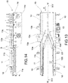
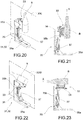
- each bottle handling device 31, 32 of the aforesaid bottle positioning system 30 comprises a bottle gripper element 33, which is movable, preferably by rotation, between:
- each bottle handling device 31, 32 comprises:
- the support frame 35 consists of an L-profile with a first horizontal portion 35a for fixing to the base 36 and a second vertical portion 35b for pivoting the gripper element 33.
- the frame 35 is associated to the actuator 37 (preferably consisting of a pneumatic cylinder).
- each bottle gripping element 33 is suitable to grip a bottle with at least one vacuum suction cup 34.
- vacuum suction cups as gripping elements is made possible in that the handling devices 31 and 32 are called upon to orient the bottles in a static operating condition, i.e. in an operating condition not associated with a simultaneous movement of the entire handling device.
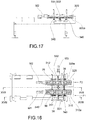
- the device for transferring bottles 40 comprises:
- the aforesaid movable bottle gripper head 41 comprises a plurality of gripper elements 42, each of which is suitable to grip a bottle B.
- the aforesaid gripper elements 42 are distributed on two parallel rows L1 and L2 to grip one or more groups of bottles B already arranged int-bêche configuration.
- each bottle gripping element 42 is suitable to grip a bottle by means of at least one vacuum suction cup 43.
- vacuum suction cups as gripper elements in the movable bottle gripper head 41 is made possible in that this movable head 41 is not required to change the relative orientation of the bottles to arrange them invit-bêche configuration, but only to transfer bottles already arranged in such configuration from one point to another of the plant 1.
- the gripper elements 42 of each row L1 and L2 are movable in relation to each other so as to adjust the pitch and thus adapt them to the bottle format. This may be achieved in a constructively simple way due to the fact that vacuum suction cups, and not mechanical clamps, may be used as gripper elements.
- the laying plant 1 is automated and comprises an electronic control unit 100 which is programmed to control at least the bottle positioning system 30 and the bottle transferring device 40 so that, while the bottle transferring device 40 is transferring one or more groups of bottles B in the27-bêche configuration towards the laying line 20 picked up by the bottle positioning system 30, the bottle positioning system 30 is preparing one or more groups of bottles in theis-bêche configuration.
- This laying method is implemented by means of a laying plant 1 comprising:
- the laying method is implemented by means of a laying plant 1 according to the present invention, and in particular as described above.
- the method according to the invention comprises the following operative steps:
- the aforesaid step a) of positioning bottles is implemented by a system 30 to position one or more groups of bottles int-bêche configuration, while the aforesaid step b) is implemented by a device 40 to transfer one or more groups of bottles int-bêche configuration into the line for laying in containers.
- the bottle positioning system 30 is structurally and functionally separate from the bottle transferring device 40.
- the bottle positioning step a) is carried out at the same time as the execution of the transferring step b) on at least one group of bottles different from that on which said transferring step b) is being performed.
- the invention allows many advantages already partly described to be obtained.
- the plant for laying bottles in ativ-bêche arrangement allows flexible management of bottle format changes, significantly reducing the need to replace the bottle transferring device in the laying line, without, however, increasing the mechanical complexity of such bottle transferring device.
- the bottle laying system according to the invention is moreover easy to manage from an operative point of view.
- bottle laying plant according to the invention is simple and economical to implement.
- the laying plant 1 may be structured to flexibly manage bottle format changes, significantly reducing the need to replace the movable device for gripping and handling bottles, without, however, increasing the mechanical complexity of the bottle transferring device.
Landscapes
- Engineering & Computer Science (AREA)
- Mechanical Engineering (AREA)
- Specific Conveyance Elements (AREA)
- Hydroponics (AREA)
- Agricultural Chemicals And Associated Chemicals (AREA)
Applications Claiming Priority (1)
| Application Number | Priority Date | Filing Date | Title |
|---|---|---|---|
| IT102018000004445A IT201800004445A1 (it) | 2018-04-12 | 2018-04-12 | Impianto e metodo di deposizione di bottiglie con disposizione tête-bêche |
Publications (2)
| Publication Number | Publication Date |
|---|---|
| EP3552978A1 true EP3552978A1 (de) | 2019-10-16 |
| EP3552978B1 EP3552978B1 (de) | 2021-03-03 |
Family
ID=63014760
Family Applications (1)
| Application Number | Title | Priority Date | Filing Date |
|---|---|---|---|
| EP19167965.3A Active EP3552978B1 (de) | 2018-04-12 | 2019-04-08 | Anlage und verfahren zum legen von flaschen in entgegengesetzter anordnung |
Country Status (2)
| Country | Link |
|---|---|
| EP (1) | EP3552978B1 (de) |
| IT (1) | IT201800004445A1 (de) |
Cited By (2)
| Publication number | Priority date | Publication date | Assignee | Title |
|---|---|---|---|---|
| CN112278376A (zh) * | 2020-09-10 | 2021-01-29 | 广州华研精密机械股份有限公司 | 一种自动化瓶胚装箱系统及方法 |
| EP3597377B1 (de) * | 2018-06-11 | 2025-10-15 | Geo Project Industries S.r.l. | Vorrichtung und verfahren zur manipulation der flowpack-verpackung von langen teigwaren |
Citations (4)
| Publication number | Priority date | Publication date | Assignee | Title |
|---|---|---|---|---|
| US3878665A (en) * | 1973-03-12 | 1975-04-22 | Chandon Handels Gmbh | Bottle packing installation |
| FR2420483A1 (fr) * | 1978-03-21 | 1979-10-19 | Lafarge Emballage | Procede de remplissage d'une caisse par des objets imbricables tete-beche |
| US20030168873A1 (en) * | 2000-07-12 | 2003-09-11 | Mario Lanfranchi | Head for transferring containers, in particular bottles, within a palletiser |
| FR2940794A1 (fr) * | 2009-01-07 | 2010-07-09 | Champaconcept | Procede et dispositif de manipulation pour la manutention et la mise en couche horizontale de bouteilles ou similaires |
-
2018
- 2018-04-12 IT IT102018000004445A patent/IT201800004445A1/it unknown
-
2019
- 2019-04-08 EP EP19167965.3A patent/EP3552978B1/de active Active
Patent Citations (4)
| Publication number | Priority date | Publication date | Assignee | Title |
|---|---|---|---|---|
| US3878665A (en) * | 1973-03-12 | 1975-04-22 | Chandon Handels Gmbh | Bottle packing installation |
| FR2420483A1 (fr) * | 1978-03-21 | 1979-10-19 | Lafarge Emballage | Procede de remplissage d'une caisse par des objets imbricables tete-beche |
| US20030168873A1 (en) * | 2000-07-12 | 2003-09-11 | Mario Lanfranchi | Head for transferring containers, in particular bottles, within a palletiser |
| FR2940794A1 (fr) * | 2009-01-07 | 2010-07-09 | Champaconcept | Procede et dispositif de manipulation pour la manutention et la mise en couche horizontale de bouteilles ou similaires |
Cited By (2)
| Publication number | Priority date | Publication date | Assignee | Title |
|---|---|---|---|---|
| EP3597377B1 (de) * | 2018-06-11 | 2025-10-15 | Geo Project Industries S.r.l. | Vorrichtung und verfahren zur manipulation der flowpack-verpackung von langen teigwaren |
| CN112278376A (zh) * | 2020-09-10 | 2021-01-29 | 广州华研精密机械股份有限公司 | 一种自动化瓶胚装箱系统及方法 |
Also Published As
| Publication number | Publication date |
|---|---|
| IT201800004445A1 (it) | 2019-10-12 |
| EP3552978B1 (de) | 2021-03-03 |
Similar Documents
| Publication | Publication Date | Title |
|---|---|---|
| CN107108134B (zh) | 用于在至少两个输送区段之内输送商品、零散货物和/或包捆物的方法和设备 | |
| US8286409B2 (en) | Method and apparatus, in a bottling plant, for packing beverage bottles in cases with and without dividers and a method and apparatus for packing containers in cases with and without dividers | |
| US9790037B2 (en) | Machine, process, container and packaging for packing tetrahedral-shaped products | |
| CN1081573C (zh) | 包装扁平物品的方法和设备 | |
| US20200180870A1 (en) | Method and apparatus for handling piece goods moved in at least two parallel rows | |
| EP4003845B1 (de) | Vorrichtung zum aufnehmen und behandeln von gegenständen | |
| US12116157B2 (en) | Modular apparatus for filling and closing articles | |
| US11530060B2 (en) | Handling apparatus and/or packaging apparatus and method used to package article groups in outer packaging | |
| ITMI20100410A1 (it) | Stazione di alimentazione e sistema di alimentazione e trattamento di flaconi comprendente tale stazione | |
| EP3552978B1 (de) | Anlage und verfahren zum legen von flaschen in entgegengesetzter anordnung | |
| CN114450227A (zh) | 包装设备 | |
| US20180170590A1 (en) | Product packaging apparatus | |
| EP4183724A1 (de) | Maschine zum positionieren von gegenständen | |
| CN116648410A (zh) | 物品拾取和放置系统 | |
| CN110603212B (zh) | 堆码机工作站 | |
| IT202300002262U1 (it) | Macchina per imballaggio di articoli | |
| ITUB20155339A1 (it) | Macchina incartonatrice con dispositivo di presa a pinza. | |
| HK1022881A (en) | Method and apparatus for packaging flat articles |
Legal Events
| Date | Code | Title | Description |
|---|---|---|---|
| PUAI | Public reference made under article 153(3) epc to a published international application that has entered the european phase |
Free format text: ORIGINAL CODE: 0009012 |
|
| STAA | Information on the status of an ep patent application or granted ep patent |
Free format text: STATUS: THE APPLICATION HAS BEEN PUBLISHED |
|
| AK | Designated contracting states |
Kind code of ref document: A1 Designated state(s): AL AT BE BG CH CY CZ DE DK EE ES FI FR GB GR HR HU IE IS IT LI LT LU LV MC MK MT NL NO PL PT RO RS SE SI SK SM TR |
|
| AX | Request for extension of the european patent |
Extension state: BA ME |
|
| STAA | Information on the status of an ep patent application or granted ep patent |
Free format text: STATUS: REQUEST FOR EXAMINATION WAS MADE |
|
| 17P | Request for examination filed |
Effective date: 20200408 |
|
| RBV | Designated contracting states (corrected) |
Designated state(s): AL AT BE BG CH CY CZ DE DK EE ES FI FR GB GR HR HU IE IS IT LI LT LU LV MC MK MT NL NO PL PT RO RS SE SI SK SM TR |
|
| GRAP | Despatch of communication of intention to grant a patent |
Free format text: ORIGINAL CODE: EPIDOSNIGR1 |
|
| STAA | Information on the status of an ep patent application or granted ep patent |
Free format text: STATUS: GRANT OF PATENT IS INTENDED |
|
| RIC1 | Information provided on ipc code assigned before grant |
Ipc: B65B 35/58 20060101ALI20200903BHEP Ipc: B65B 21/20 20060101ALI20200903BHEP Ipc: B65B 59/00 20060101ALI20200903BHEP Ipc: B65B 21/02 20060101AFI20200903BHEP |
|
| INTG | Intention to grant announced |
Effective date: 20200928 |
|
| GRAS | Grant fee paid |
Free format text: ORIGINAL CODE: EPIDOSNIGR3 |
|
| GRAA | (expected) grant |
Free format text: ORIGINAL CODE: 0009210 |
|
| STAA | Information on the status of an ep patent application or granted ep patent |
Free format text: STATUS: THE PATENT HAS BEEN GRANTED |
|
| AK | Designated contracting states |
Kind code of ref document: B1 Designated state(s): AL AT BE BG CH CY CZ DE DK EE ES FI FR GB GR HR HU IE IS IT LI LT LU LV MC MK MT NL NO PL PT RO RS SE SI SK SM TR |
|
| REG | Reference to a national code |
Ref country code: GB Ref legal event code: FG4D |
|
| REG | Reference to a national code |
Ref country code: CH Ref legal event code: EP Ref country code: AT Ref legal event code: REF Ref document number: 1366969 Country of ref document: AT Kind code of ref document: T Effective date: 20210315 |
|
| REG | Reference to a national code |
Ref country code: DE Ref legal event code: R096 Ref document number: 602019002860 Country of ref document: DE |
|
| REG | Reference to a national code |
Ref country code: IE Ref legal event code: FG4D |
|
| REG | Reference to a national code |
Ref country code: LT Ref legal event code: MG9D |
|
| PG25 | Lapsed in a contracting state [announced via postgrant information from national office to epo] |
Ref country code: BG Free format text: LAPSE BECAUSE OF FAILURE TO SUBMIT A TRANSLATION OF THE DESCRIPTION OR TO PAY THE FEE WITHIN THE PRESCRIBED TIME-LIMIT Effective date: 20210603 Ref country code: FI Free format text: LAPSE BECAUSE OF FAILURE TO SUBMIT A TRANSLATION OF THE DESCRIPTION OR TO PAY THE FEE WITHIN THE PRESCRIBED TIME-LIMIT Effective date: 20210303 Ref country code: GR Free format text: LAPSE BECAUSE OF FAILURE TO SUBMIT A TRANSLATION OF THE DESCRIPTION OR TO PAY THE FEE WITHIN THE PRESCRIBED TIME-LIMIT Effective date: 20210604 Ref country code: HR Free format text: LAPSE BECAUSE OF FAILURE TO SUBMIT A TRANSLATION OF THE DESCRIPTION OR TO PAY THE FEE WITHIN THE PRESCRIBED TIME-LIMIT Effective date: 20210303 Ref country code: NO Free format text: LAPSE BECAUSE OF FAILURE TO SUBMIT A TRANSLATION OF THE DESCRIPTION OR TO PAY THE FEE WITHIN THE PRESCRIBED TIME-LIMIT Effective date: 20210603 Ref country code: LT Free format text: LAPSE BECAUSE OF FAILURE TO SUBMIT A TRANSLATION OF THE DESCRIPTION OR TO PAY THE FEE WITHIN THE PRESCRIBED TIME-LIMIT Effective date: 20210303 |
|
| REG | Reference to a national code |
Ref country code: NL Ref legal event code: MP Effective date: 20210303 |
|
| REG | Reference to a national code |
Ref country code: AT Ref legal event code: MK05 Ref document number: 1366969 Country of ref document: AT Kind code of ref document: T Effective date: 20210303 |
|
| PG25 | Lapsed in a contracting state [announced via postgrant information from national office to epo] |
Ref country code: SE Free format text: LAPSE BECAUSE OF FAILURE TO SUBMIT A TRANSLATION OF THE DESCRIPTION OR TO PAY THE FEE WITHIN THE PRESCRIBED TIME-LIMIT Effective date: 20210303 Ref country code: RS Free format text: LAPSE BECAUSE OF FAILURE TO SUBMIT A TRANSLATION OF THE DESCRIPTION OR TO PAY THE FEE WITHIN THE PRESCRIBED TIME-LIMIT Effective date: 20210303 Ref country code: PL Free format text: LAPSE BECAUSE OF FAILURE TO SUBMIT A TRANSLATION OF THE DESCRIPTION OR TO PAY THE FEE WITHIN THE PRESCRIBED TIME-LIMIT Effective date: 20210303 Ref country code: LV Free format text: LAPSE BECAUSE OF FAILURE TO SUBMIT A TRANSLATION OF THE DESCRIPTION OR TO PAY THE FEE WITHIN THE PRESCRIBED TIME-LIMIT Effective date: 20210303 |
|
| PG25 | Lapsed in a contracting state [announced via postgrant information from national office to epo] |
Ref country code: NL Free format text: LAPSE BECAUSE OF FAILURE TO SUBMIT A TRANSLATION OF THE DESCRIPTION OR TO PAY THE FEE WITHIN THE PRESCRIBED TIME-LIMIT Effective date: 20210303 |
|
| PG25 | Lapsed in a contracting state [announced via postgrant information from national office to epo] |
Ref country code: AT Free format text: LAPSE BECAUSE OF FAILURE TO SUBMIT A TRANSLATION OF THE DESCRIPTION OR TO PAY THE FEE WITHIN THE PRESCRIBED TIME-LIMIT Effective date: 20210303 Ref country code: SM Free format text: LAPSE BECAUSE OF FAILURE TO SUBMIT A TRANSLATION OF THE DESCRIPTION OR TO PAY THE FEE WITHIN THE PRESCRIBED TIME-LIMIT Effective date: 20210303 Ref country code: EE Free format text: LAPSE BECAUSE OF FAILURE TO SUBMIT A TRANSLATION OF THE DESCRIPTION OR TO PAY THE FEE WITHIN THE PRESCRIBED TIME-LIMIT Effective date: 20210303 Ref country code: CZ Free format text: LAPSE BECAUSE OF FAILURE TO SUBMIT A TRANSLATION OF THE DESCRIPTION OR TO PAY THE FEE WITHIN THE PRESCRIBED TIME-LIMIT Effective date: 20210303 |
|
| REG | Reference to a national code |
Ref country code: DE Ref legal event code: R119 Ref document number: 602019002860 Country of ref document: DE |
|
| PG25 | Lapsed in a contracting state [announced via postgrant information from national office to epo] |
Ref country code: PT Free format text: LAPSE BECAUSE OF FAILURE TO SUBMIT A TRANSLATION OF THE DESCRIPTION OR TO PAY THE FEE WITHIN THE PRESCRIBED TIME-LIMIT Effective date: 20210705 Ref country code: RO Free format text: LAPSE BECAUSE OF FAILURE TO SUBMIT A TRANSLATION OF THE DESCRIPTION OR TO PAY THE FEE WITHIN THE PRESCRIBED TIME-LIMIT Effective date: 20210303 Ref country code: SK Free format text: LAPSE BECAUSE OF FAILURE TO SUBMIT A TRANSLATION OF THE DESCRIPTION OR TO PAY THE FEE WITHIN THE PRESCRIBED TIME-LIMIT Effective date: 20210303 Ref country code: IS Free format text: LAPSE BECAUSE OF FAILURE TO SUBMIT A TRANSLATION OF THE DESCRIPTION OR TO PAY THE FEE WITHIN THE PRESCRIBED TIME-LIMIT Effective date: 20210703 |
|
| PG25 | Lapsed in a contracting state [announced via postgrant information from national office to epo] |
Ref country code: LU Free format text: LAPSE BECAUSE OF NON-PAYMENT OF DUE FEES Effective date: 20210408 |
|
| PLBE | No opposition filed within time limit |
Free format text: ORIGINAL CODE: 0009261 |
|
| STAA | Information on the status of an ep patent application or granted ep patent |
Free format text: STATUS: NO OPPOSITION FILED WITHIN TIME LIMIT |
|
| REG | Reference to a national code |
Ref country code: BE Ref legal event code: MM Effective date: 20210430 |
|
| PG25 | Lapsed in a contracting state [announced via postgrant information from national office to epo] |
Ref country code: ES Free format text: LAPSE BECAUSE OF FAILURE TO SUBMIT A TRANSLATION OF THE DESCRIPTION OR TO PAY THE FEE WITHIN THE PRESCRIBED TIME-LIMIT Effective date: 20210303 Ref country code: MC Free format text: LAPSE BECAUSE OF FAILURE TO SUBMIT A TRANSLATION OF THE DESCRIPTION OR TO PAY THE FEE WITHIN THE PRESCRIBED TIME-LIMIT Effective date: 20210303 Ref country code: AL Free format text: LAPSE BECAUSE OF FAILURE TO SUBMIT A TRANSLATION OF THE DESCRIPTION OR TO PAY THE FEE WITHIN THE PRESCRIBED TIME-LIMIT Effective date: 20210303 Ref country code: DE Free format text: LAPSE BECAUSE OF NON-PAYMENT OF DUE FEES Effective date: 20211103 Ref country code: DK Free format text: LAPSE BECAUSE OF FAILURE TO SUBMIT A TRANSLATION OF THE DESCRIPTION OR TO PAY THE FEE WITHIN THE PRESCRIBED TIME-LIMIT Effective date: 20210303 |
|
| 26N | No opposition filed |
Effective date: 20211206 |
|
| PG25 | Lapsed in a contracting state [announced via postgrant information from national office to epo] |
Ref country code: SI Free format text: LAPSE BECAUSE OF FAILURE TO SUBMIT A TRANSLATION OF THE DESCRIPTION OR TO PAY THE FEE WITHIN THE PRESCRIBED TIME-LIMIT Effective date: 20210303 |
|
| PG25 | Lapsed in a contracting state [announced via postgrant information from national office to epo] |
Ref country code: IE Free format text: LAPSE BECAUSE OF NON-PAYMENT OF DUE FEES Effective date: 20210408 |
|
| PG25 | Lapsed in a contracting state [announced via postgrant information from national office to epo] |
Ref country code: IS Free format text: LAPSE BECAUSE OF FAILURE TO SUBMIT A TRANSLATION OF THE DESCRIPTION OR TO PAY THE FEE WITHIN THE PRESCRIBED TIME-LIMIT Effective date: 20210703 |
|
| PG25 | Lapsed in a contracting state [announced via postgrant information from national office to epo] |
Ref country code: BE Free format text: LAPSE BECAUSE OF NON-PAYMENT OF DUE FEES Effective date: 20210430 |
|
| REG | Reference to a national code |
Ref country code: CH Ref legal event code: PL |
|
| PG25 | Lapsed in a contracting state [announced via postgrant information from national office to epo] |
Ref country code: LI Free format text: LAPSE BECAUSE OF NON-PAYMENT OF DUE FEES Effective date: 20220430 Ref country code: CH Free format text: LAPSE BECAUSE OF NON-PAYMENT OF DUE FEES Effective date: 20220430 |
|
| PG25 | Lapsed in a contracting state [announced via postgrant information from national office to epo] |
Ref country code: CY Free format text: LAPSE BECAUSE OF FAILURE TO SUBMIT A TRANSLATION OF THE DESCRIPTION OR TO PAY THE FEE WITHIN THE PRESCRIBED TIME-LIMIT Effective date: 20210303 |
|
| PG25 | Lapsed in a contracting state [announced via postgrant information from national office to epo] |
Ref country code: HU Free format text: LAPSE BECAUSE OF FAILURE TO SUBMIT A TRANSLATION OF THE DESCRIPTION OR TO PAY THE FEE WITHIN THE PRESCRIBED TIME-LIMIT; INVALID AB INITIO Effective date: 20190408 |
|
| GBPC | Gb: european patent ceased through non-payment of renewal fee |
Effective date: 20230408 |
|
| PG25 | Lapsed in a contracting state [announced via postgrant information from national office to epo] |
Ref country code: GB Free format text: LAPSE BECAUSE OF NON-PAYMENT OF DUE FEES Effective date: 20230408 |
|
| PG25 | Lapsed in a contracting state [announced via postgrant information from national office to epo] |
Ref country code: GB Free format text: LAPSE BECAUSE OF NON-PAYMENT OF DUE FEES Effective date: 20230408 |
|
| PG25 | Lapsed in a contracting state [announced via postgrant information from national office to epo] |
Ref country code: MK Free format text: LAPSE BECAUSE OF FAILURE TO SUBMIT A TRANSLATION OF THE DESCRIPTION OR TO PAY THE FEE WITHIN THE PRESCRIBED TIME-LIMIT Effective date: 20210303 |
|
| PG25 | Lapsed in a contracting state [announced via postgrant information from national office to epo] |
Ref country code: TR Free format text: LAPSE BECAUSE OF FAILURE TO SUBMIT A TRANSLATION OF THE DESCRIPTION OR TO PAY THE FEE WITHIN THE PRESCRIBED TIME-LIMIT Effective date: 20210303 |
|
| PG25 | Lapsed in a contracting state [announced via postgrant information from national office to epo] |
Ref country code: MT Free format text: LAPSE BECAUSE OF FAILURE TO SUBMIT A TRANSLATION OF THE DESCRIPTION OR TO PAY THE FEE WITHIN THE PRESCRIBED TIME-LIMIT Effective date: 20210303 |
|
| PGFP | Annual fee paid to national office [announced via postgrant information from national office to epo] |
Ref country code: IT Payment date: 20260204 Year of fee payment: 8 |
|
| PGFP | Annual fee paid to national office [announced via postgrant information from national office to epo] |
Ref country code: FR Payment date: 20260331 Year of fee payment: 8 |