EP3552981B1 - Outil de cerclage portable combiné électrique - Google Patents
Outil de cerclage portable combiné électrique Download PDFInfo
- Publication number
- EP3552981B1 EP3552981B1 EP19178524.5A EP19178524A EP3552981B1 EP 3552981 B1 EP3552981 B1 EP 3552981B1 EP 19178524 A EP19178524 A EP 19178524A EP 3552981 B1 EP3552981 B1 EP 3552981B1
- Authority
- EP
- European Patent Office
- Prior art keywords
- strap
- strapping tool
- tool
- control system
- sealing
- Prior art date
- Legal status (The legal status is an assumption and is not a legal conclusion. Google has not performed a legal analysis and makes no representation as to the accuracy of the status listed.)
- Active
Links
Images




Classifications
-
- B—PERFORMING OPERATIONS; TRANSPORTING
- B65—CONVEYING; PACKING; STORING; HANDLING THIN OR FILAMENTARY MATERIAL
- B65B—MACHINES, APPARATUS OR DEVICES FOR, OR METHODS OF, PACKAGING ARTICLES OR MATERIALS; UNPACKING
- B65B13/00—Bundling articles
- B65B13/02—Applying and securing binding material around articles or groups of articles, e.g. using strings, wires, strips, bands or tapes
- B65B13/025—Hand-held tools
-
- B—PERFORMING OPERATIONS; TRANSPORTING
- B65—CONVEYING; PACKING; STORING; HANDLING THIN OR FILAMENTARY MATERIAL
- B65B—MACHINES, APPARATUS OR DEVICES FOR, OR METHODS OF, PACKAGING ARTICLES OR MATERIALS; UNPACKING
- B65B13/00—Bundling articles
- B65B13/18—Details of, or auxiliary devices used in, bundling machines or bundling tools
- B65B13/185—Details of tools
- B65B13/187—Motor means
-
- B—PERFORMING OPERATIONS; TRANSPORTING
- B65—CONVEYING; PACKING; STORING; HANDLING THIN OR FILAMENTARY MATERIAL
- B65B—MACHINES, APPARATUS OR DEVICES FOR, OR METHODS OF, PACKAGING ARTICLES OR MATERIALS; UNPACKING
- B65B13/00—Bundling articles
- B65B13/18—Details of, or auxiliary devices used in, bundling machines or bundling tools
- B65B13/22—Means for controlling tension of binding means
-
- B—PERFORMING OPERATIONS; TRANSPORTING
- B65—CONVEYING; PACKING; STORING; HANDLING THIN OR FILAMENTARY MATERIAL
- B65B—MACHINES, APPARATUS OR DEVICES FOR, OR METHODS OF, PACKAGING ARTICLES OR MATERIALS; UNPACKING
- B65B13/00—Bundling articles
- B65B13/18—Details of, or auxiliary devices used in, bundling machines or bundling tools
- B65B13/24—Securing ends of binding material
- B65B13/30—Securing ends of binding material by deforming the overlapping ends of the strip or band
- B65B13/305—Hand tools
-
- B—PERFORMING OPERATIONS; TRANSPORTING
- B65—CONVEYING; PACKING; STORING; HANDLING THIN OR FILAMENTARY MATERIAL
- B65B—MACHINES, APPARATUS OR DEVICES FOR, OR METHODS OF, PACKAGING ARTICLES OR MATERIALS; UNPACKING
- B65B57/00—Automatic control, checking, warning, or safety devices
-
- B—PERFORMING OPERATIONS; TRANSPORTING
- B65—CONVEYING; PACKING; STORING; HANDLING THIN OR FILAMENTARY MATERIAL
- B65B—MACHINES, APPARATUS OR DEVICES FOR, OR METHODS OF, PACKAGING ARTICLES OR MATERIALS; UNPACKING
- B65B57/00—Automatic control, checking, warning, or safety devices
- B65B57/18—Automatic control, checking, warning, or safety devices causing operation of audible or visible alarm signals
-
- B—PERFORMING OPERATIONS; TRANSPORTING
- B65—CONVEYING; PACKING; STORING; HANDLING THIN OR FILAMENTARY MATERIAL
- B65B—MACHINES, APPARATUS OR DEVICES FOR, OR METHODS OF, PACKAGING ARTICLES OR MATERIALS; UNPACKING
- B65B2210/00—Specific aspects of the packaging machine
- B65B2210/12—Means for automatically detecting and removing jammed straps in strapping machines, e.g. jam clearing devices
Definitions
- Strapping tools or strappers come in a wide variety of types, from fully manual hand tools to automatic, table-top machines. Strapping tools can be designed and intended for use with different types of strap or strapping materials, such as metal strapping or plastic/polymeric strapping. Strappers for metal strapping materials can be automatic table-top or hand-held devices that are configured to seal the strap onto itself. The sealing function can be performed using a sealless configuration by forming interlocking keys in overlapping courses of the strap, or by applying a seal that is positioned over and crimped onto the overlapping strap courses.
- manual tools that require an operator to exert one or more forces to tension the strap and form the seal
- pneumatically operated tools that perform the tension and sealing functions by actuation of one or more pneumatic motors.
- the manual tools can be fatiguing to operate for long periods of time and may be difficult to maneuver and manipulate in certain instances, for example when the seal is formed on the side of a package or load.
- manual sealing typically requires multiple tools to tension the strap, form the seal and cut the sealed strap from its source.
- Pneumatic tools such as that disclosed in Crittenden, US Patent No. 6,079,457 , commonly assigned with the present application, function well; however, they require a source of compressed gas, such as air, and thus necessitate the use of hoses, compressed gas fittings and the like for operation.
- a source of compressed gas such as air
- pneumatic tools may be limited in certain applications where, for example, the strapping operations are carried out at different locations throughout a manufacturing facility.
- pneumatic tools employ pneumatic motors which can be costly, and pneumatic circuits which can be complex and require casting and machining operations in the manufacture of pneumatic circuit modules.
- Another pneumatic tool is known from US 6,966,255 B1 .
- US 5 694 984 A discloses an improvement in a punch design for a punch used within a strapping tool, where the punch is relieved along the edge surfaces that experiences extreme forces during a stamping operation.
- a powered strapping tool that functions to tension strap around a load, form a seal in the overlapping courses of strap material and cut the sealed strap from its source.
- a tool is self-contained, is electrically and/or battery powered, and is thus portable and can be used throughout a facility at any location. More desirably still, such a tool can be used in a variety of operating modes.
- a strapping tool for tensioning and forming a sealless joint in overlapping sections of steel strap around a load that includes a body having a foot, a tensioning assembly operably mounted to the body and a sealing assembly operably mounted to the body.
- the tensioning and sealing assemblies have electrically powered motors.
- a tensioning wheel is operably connected to the tensioner motor and a sealer is operably connected to the sealer motor.
- the tool includes a control system for controlling operation of the tensioning assembly and the sealing assembly.
- the control system is configured to operate the strapping tool in an automatic mode in which the tensioning assembly and the sealing assembly are sequentially actuated by, for example, a single action of the control system by an operator, and in a manual mode in which the tensioning assembly and the sealing assembly are sequentially actuated by multiple actions of the control system by the operator.
- An automatic mode is already known from non-generic prior art document EP 2 711 301 A1 .
- the sealing assembly includes a die and punch cooperating with one another to cut keys in the overlapping sections of strap.
- the tensioner motor is operated in a reverse direction following a sealing cycle to interlock the keys cut in the overlapping sections of strap.
- the control system in the automatic mode, is configured to operate in the reverse direction following the sealing assembly actuation by action of the control system to interlock the keys. In an embodiment the action can be carried out by a single action of the control system.
- the tensioner motor assembly is pivotally mounted to the body and is biased to move the tension wheel toward the foot.
- a cam shaft is operably connected to the die and includes a position switch for sensing a position of the cam shaft.
- the position switch is operably connected to the control system.
- An embodiment of the tool includes a dynamic brake to stop rotation of the sealer motor assembly at an end of the sealing cycle. The dynamic brake can be controlled by the control system.
- the tool includes an actuation switch for controlling the tool.
- the actuation switch is operably connected to the control system which is operably connected to the tensioner motor assembly and the sealer motor assembly.
- the control system can include a strap tension adjusting device for varying a tension in the overlapping sections of steel strap.
- the control system can be configure to stop movement of the tensioning wheel based upon a setting of the strap tension adjusting device.
- a control system controls a strapping tool of the type for tensioning and forming a sealless joint in overlapping sections of steel strap around a load.
- the control system includes control circuitry operably connected to the tensioner motor assembly and the sealer motor assembly.
- a position switch is operably connected to the sealer to determine a position of the seal.
- the control system includes an actuation switch.
- the control system is configured to operate the strapping tool in an automatic mode in which the tensioner motor assembly and the sealer motor assembly are sequentially actuated by a single action of the actuation switch.
- the control system is operably connected to a dynamic brake to stop movement of the sealer motor assembly when the sealer reaches a predetermined position.
- control system actuates the tensioner motor assembly in a reverse direction to secure the sealless joint.
- the tool 10 is configured to tension steel strap S or strapping material around an object or load L, seal overlapping portions of the strap S to itself at a seal or joint J to form a tensioned loop around the load L and to cut the tensioned loop from the strap supply P.
- the strap S includes a feed or supply end P and a free end F that is fed around the load L and reinserted into the tool 10 to overlap the supply end P.
- sealless refers to the configuration or type of seal or joint that is made in the overlapping portions of the strap. Although a “seal” is made in the strap courses, the sealless joint is made by cutting or punching interlocking keys K or sections of the courses, as illustrated in FIG. 7 .
- the term sealless is intended to define this type of joint or seal J as compared to a joint that is made using a separate element such as a crimp seal that is applied over and crimped onto the overlapping strap courses.
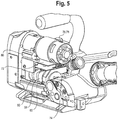
- the tool 10 includes a body 12, a tensioning section 14 and a sealing section 16.
- the tensioning section 14 includes a housing 18 and a first or tensioner motor assembly 20 operably mounted to the body 12.
- the sealing section 16 includes a sealer 21, housing 22 and a second or sealer motor assembly 24 operably mounted to the body 12.
- the body 12 includes a foot 26, a housing 28 and one or more handles 30 and 32 to facilitate handling and using the tool 10.
- One handle can be a tool opening handle 30 above the tensioner motor assembly 20 and the other an operating handle 32 mounted above the body 12.
- a receiver 34 is formed as part of or mounted to the body 12 for receiving a battery 36 or other power source.
- a temporary hold-down finger 38 can be positioned on the foot 12, opposite the tensioner motor assembly 20. The hold-down finger can be biased toward the foot 26.
- the tensioning section 14 includes the tensioner motor assembly 20, which has a motor 40, such as a DC motor, and a gear housing 42 including a gear set 44 to convert the motor 40 output drive to a usable speed.
- the gear 44 set can include a planetary gear set (not shown) to reduce the output speed and to increase the output power or torque from the motor 40.
- the gear set 44 includes a final drive (not shown) that meshes with a gear (not shown) on a tension wheel 46.
- the tension wheel 46 is mounted normal to the final-drive.
- the gear set 44 and final drive are housed in the gear housing 18 mounted to the tool body 12.
- a gripping pad 48 can be positioned in the foot 26, opposite the tension wheel 46.
- the tensioner motor assembly 20, gear housing 42 and tension wheel 46 are movably mounted to the body 12 to move the tension wheel 46 toward and away from the foot 26. This permits the tool 10 to be opened to position the strap S between the foot 26 and the tension wheel 46.
- the tensioner motor assembly 20, gear housing 42 and tension wheel 46 are pivotably mounted to the body 12 to pivot the tension wheel 46 toward and away from the foot 26.
- the tensioner motor assembly 20, gear housing 42 and tension wheel 46 can be biasedly mounted to the body 12, such as by a spring (not shown), to bias the tension wheel 46 toward the foot 26 and into contact with the strap S in the closed position.
- the sealing section 16 includes the sealer motor assembly 24 which has a motor 50, such as a DC motor and a drive 52.
- the drive 52 is a gear set 54 that includes a planetary gear set (not shown) that drives a cam shaft 56 through a final drive gear (not shown).
- the planetary gear set reduces the output speed and increases the output power or torque from the motor 50.
- Other drives can be used to transfer power from the motor 50 to the cam shaft 56, such as belts, chains or the like.
- Cams 58 on the cam shaft 56 contact and moves a set of dies 60 in the sealing section 16.
- the dies 60 reciprocate toward and away from a punch 62 located on the foot 26 to bring the dies 60 into and out of contact with the overlapping course of strap S positioned between the dies 60 and the punch 62.
- the dies 60 and punch 62 form keys K in the strap S that, when shifted longitudinally, lock into one another.
- An example of a sealer section 16 is illustrated in FIG. 8 and an example of an interlocking key K seal or joint J is illustrated in FIG. 7 .
- the sealing section 16 also includes a cutter 64 to cut the looped and sealed strap S from the strap supply P during the sealing cycle. Similar to the dies 60, the cutter 64 is driven by the rotation of the cam shaft 56.
- the tool 10 is configured to permit operation in fully automatic and manual modes.
- the tool 10 includes a control system, shown generally at 66, to control operation of the tool 10.
- the tool 10 includes an actuation 68 switch and one or more circuits 70, 72 to control the tensioner motor 40 and the sealing motor 50.
- the tensioner motor and sealing motor circuits 70, 72 are provided on separate boards within the tool 10. It will be appreciated that the tensioner and sealer motor boards 70, 72 can be combined on a single board.
- the control system 66 can further include a cam position switch or sensor 74 to sense the position of the cam shaft 56 in the sealing section 16, a strap size/tension adjustment device 76, an anti-jam device 78 and a dynamic brake 80.
- the cam position switch 74 is positioned to determine the position of the cam shaft 56 and thus the position of the cam lobes 58 (or cams), and consequently the dies 60 and cutter 64.
- the strap size/tension adjustment device 76 can be, for example, a knob-type dial adjustment provided on the tool body 12. Control of the anti-jam device 78 can be incorporated within the tension/strap size adjustment dial 76.
- the dynamic brake 80 is associated with the sealing motor 50 to brake or stop the motor 50 when the cam shaft 56 is at a home position and to bleed power from the motor 50 at the completion of the sealing cycle.
- the tool 10 can further include one or more indicators, such as LEDs, to provide indication of certain functions and states of the tool.
- An LED indicator 82 can be positioned within or around the actuation switch 68.
- the tool 10 in an operating scenario, is in a home position in which the spring biases the tension wheel 46 into contact with the foot 26.
- the tool 10 turns on and runs a self-test, as at step 104.
- An indicator such as the LED 84 in the actuation switch 68, can be configured to flash in a predetermined sequence to indicate the operating state of the tool 10.
- the LED 84 can flash once to indicate that the tool 10 is in an automatic operating mode and twice to indicate that the tool 10 is in a manual operating mode.
- the tensioner and sealer motors 40 and 50 are off (no power to the motors), and the tool 10 is ready for operation in an automatic mode or a manual mode.
- the tool 10 is opened by urging or pulling the tensioner motor assembly 20 toward the tensioner handle 30 to open a gap between the tension wheel 46 and the foot 26.
- a lead or free end F of the strap S is positioned around the load and a supply end P of the strap S (from a strap dispenser) is positioned overlapping the free end F.
- the overlapping courses of strap S are positioned in the tool 10 between the tension wheel 46 and the foot 26 and between the dies 60 and punch 62 with the supply end P entering from the rear end (the tension wheel 46 end) of the tool 10 as illustrated in FIGS. 8 and 9 , with the strap S courses positioned under the hold-down finger 38.
- depressing and releasing the actuation switch 68 commences the operating cycle.
- the tension cycle starts, as at step 108, in which the tensioner motor 40 operates to drive the tension wheel 46 to draw tension in the strap S.
- the actuation switch LED 84 is illuminated.
- a predetermined amount of tension is drawn (as set by using the strap size/tension adjustment knob 76)
- the tensioner motor 40 stops and the LED indicator 84 goes out.
- the sealing cycle then starts, as at step 110, in which the sealing motor 50 operates to rotate the cam shaft 56 and the cams 58 move into contact with and move the dies 60 downward to contact the strap S.
- the actuation switch LED 84 illuminates to indicate tool 10 operation.
- the interlocking keys K are cut by the force of the cams 58 on the dies 60 forcing the dies 60 into the strap S and forcing the strap S against the punch 62.
- the strap supply P end is cut to separate the looped strap S from the strap supply P.
- the sealing motor 50 continues to operate, and when the cam shaft 56 completes one full (360 degree) revolution, the cam switch or sensor 74 is triggered and the sealing motor 50 turns off.
- the dynamic brake 80 stops the cam shaft 56 at the home position by absorbing excess energy from the sealing motor 50.
- the hold-down finger 38 at the foot 26 holds the strap S temporarily in place in the tool 10.
- the tensioner motor 40 operates in reverse for a short period (less than about 1 second) to allow the tension in the strap S to "pull" the keys K into an interlocking arrangement (see, FIG. 7 ), which forms the seal or joint J.
- the LED indicator 84 goes out.
- the tool 10 is then in the ready/sleep state.
- depressing and releasing the actuation switch 68 at any time during the tension and/or sealing cycles can, for example, stop the tool 10, and depressing and holding the actuation switch 68, as at step 114, can operate the tensioner motor 40 in reverse. This functions as an emergency stop of the tool 10.
- the tool 10 can also be operated in manual mode in which, for example, a first depression of the actuation switch 68 commences the tension cycle, and the tensioner motor 40 stops when a predetermined tension is reached.
- a second depression of the actuation switch 68 may then be required to commence the sealing cycle.
- the auto-stop functions (for example, depressing and/or depressing and holding the actuation switch) can again serve to stop the tool 10 and/or reverse the tensioner motor 10 in manual mode.
- Trigger Function (1) when in Ready mode 106, will begin the tensioning cycle; Trigger Function (2) (-) when in Ready mode 106, will cause the tool to reverse until the trigger is released; and Trigger Function (3) (•) at any time during the tension cycle will stop the motor, where (•) indicates that the trigger is held for less than a specified period of time and (-) indicates that the trigger is held for more than a specified period of time.
- the tool 10 can include an anti-jam feature 78 actuation of which can be incorporated into the strap size/tension adjusting device 76.
- the tensioner motor 40 operates in reverse to clear any material that may be jammed in the tool 10, between the tension wheel 46 and the foot 26.
- the sealing motor 50 will cycle once, also to clear any material that may be jammed in the tool 10.
- the tool 10 as disclosed and described is an electrically powered tool that uses a battery 36; it will however be appreciated that the tool 10 can be configured to operate with a voltage converter (not shown) for example, for use at line voltages (e.g., 120V-240V).
- a voltage converter not shown
- line voltages e.g. 120V-240V
- the tool 10 is described as including a tensioner motor 40 and a scaling motor 50, it is contemplated that a single motor can be used to carry out both the tension and sealing functions with appropriate drives in place.
Landscapes
- Engineering & Computer Science (AREA)
- Mechanical Engineering (AREA)
- Basic Packing Technique (AREA)
Claims (13)
- Outil de cerclage (10) destiné à mettre en tension et à former un sertissage sans cachet (J) en sections se chevauchant de ruban d'acier (S) autour d'une charge (L), comprenant :un corps (12) ayant un pied (26) ;un ou deux moteurs électriques (40, 50) ;une section de mise en tension (14) incluant une roue tendeuse (46) reliée en fonctionnement à l'un desdits un ou deux moteurs (40, 50) et conçue pour mettre le ruban (S) en tension ; etune section de scellage (16) incluant une sertisseuse (21) reliée en fonctionnement à l'un desdits un ou deux moteurs (40, 50) et conçue pour former le sertissage sans cachet (J) ;caractérisé parun système de commande (66) pour commander le fonctionnement de l'outil (10),dans lequel la section de scellage (16) inclut une matrice (60) coopérant avec un poinçon (62) pour découper des clavettes (K) dans les sections se chevauchant de ruban (S) pendant un cycle de scellage,dans lequel le système de commande (66) est configuré pour faire fonctionner le moteur desdits un ou deux moteurs (40, 50) relié en fonctionnement à la roue tendeuse (46) pour mettre en tension le ruban pendant un cycle de mise en tension et l'outil de cerclage étant caractérisé en ce que le système de commande est en outre configuré pour faire fonctionner le moteur desdits un ou deux moteurs (40, 50) relié en fonctionnement à la roue tendeuse dans une direction inverse suite au cycle de scellage pour verrouiller les clavettes (K) découpées dans les sections se chevauchant de ruban (S).
- Outil de cerclage (10) selon la revendication 1, comprenant un interrupteur d'actionnement (68), dans lequel le système de commande (66) est configuré pour faire fonctionner l'outil de cerclage (10) dans un mode automatique dans lequel la roue tendeuse (46) et la sertisseuse (21) de la section de scellage (16) sont actionnées en séquence par le système de commande (66) en réponse à une unique action de l'interrupteur d'actionnement (68) par un opérateur pour exécuter les cycles de mise en tension et de scellage pour respectivement mettre en tension et sceller le ruban.
- Outil de cerclage (10) selon la revendication 2, dans lequel le système de commande (66) est configuré pour faire fonctionner l'outil de cerclage (10) dans un mode manuel dans lequel la roue tendeuse (46) et la sertisseuse (21) sont actionnées en séquence par le système de commande (66) en réponse à de multiples actionnements de l'interrupteur d'actionnement (68) par l'opérateur pour respectivement mettre en tension et sceller le ruban.
- Outil de cerclage (10) selon la revendication 1, comprenant un moteur de tensionneur (40) relié en fonctionnement à et conçu pour entraîner la roue tendeuse (46) et un moteur de sertisseuse distinct (50) relié en fonctionnement à et conçu pour entraîner la sertisseuse (21) de la section de scellage (16).
- Outil de cerclage selon la revendication 1, comprenant un unique moteur relié en fonctionnement à et conçu pour entraîner à la fois la roue tendeuse (46) et la sertisseuse (21) de la section de scellage (16).
- Outil de cerclage (10) selon la revendication 1, dans lequel la roue tendeuse (46) est montée sur le corps (12) et mobile vers et à distance du pied (26).
- Outil de cerclage (10) selon la revendication 1, dans lequel la roue tendeuse (46) est polarisée en contact avec le pied (26).
- Outil de cerclage (10) selon la revendication 1, 4 ou 5, comprenant en outre un train d'engrenages (44) reliant en fonctionnement le moteur du ou des deux moteurs (40, 50) à la roue tendeuse (46) et un train d'engrenages (54) reliant en fonctionnement le moteur du ou des deux moteurs (40, 50) à la sertisseuse (21) de la section de scellage (16).
- Outil de cerclage (10) selon la revendication 1, dans lequel une sertisseuse (21) de la section de scellage (16) comprend un arbre à came (56) comprenant une came (58) qui vient en prise avec la matrice (60), dans lequel la rotation de l'arbre à came (56) entraîne un mouvement en va-et-vient de la matrice (60) en direction et à distance du poinçon (62) pour découper les clavettes (K) dans les sections se chevauchant du ruban (S).
- Outil de cerclage (10) selon la revendication 9, dans lequel le système de commande (66) est en outre configuré pour arrêter la rotation de l'arbre à came (56) à la fin d'un cycle de scellage.
- Outil de cerclage (10) selon la revendication 10, comprenant en outre un commutateur de position de came (74) conçu pour détecter la position de l'arbre à came (56) .
- Outil de cerclage (10) selon la revendication 10, comprenant en outre un frein dynamique (80) conçu pour arrêter la rotation de l'arbre à came (56), dans lequel le système de commande (66) est configuré pour commander le frein dynamique (80) pour arrêter la rotation de l'arbre à came (56) à la fin d'un cycle de scellage.
- Outil de cerclage (10) selon la revendication 1, comprenant en outre un taquet de retenue (38) polarisé en direction du pied (12) et conçu pour retenir le ruban (S) en place sur le pied (12).
Applications Claiming Priority (4)
| Application Number | Priority Date | Filing Date | Title |
|---|---|---|---|
| US201462026865P | 2014-07-21 | 2014-07-21 | |
| US14/736,383 US10308383B2 (en) | 2014-07-21 | 2015-06-11 | Electrically powered combination hand-held strapping tool |
| EP15797474.2A EP3172135B1 (fr) | 2014-07-21 | 2015-06-12 | Outil de cerclage mixte portatif électrique |
| PCT/US2015/035477 WO2016014167A1 (fr) | 2014-07-21 | 2015-06-12 | Outil de cerclage mixte portatif électrique |
Related Parent Applications (1)
| Application Number | Title | Priority Date | Filing Date |
|---|---|---|---|
| EP15797474.2A Division EP3172135B1 (fr) | 2014-07-21 | 2015-06-12 | Outil de cerclage mixte portatif électrique |
Publications (2)
| Publication Number | Publication Date |
|---|---|
| EP3552981A1 EP3552981A1 (fr) | 2019-10-16 |
| EP3552981B1 true EP3552981B1 (fr) | 2020-10-07 |
Family
ID=55073932
Family Applications (2)
| Application Number | Title | Priority Date | Filing Date |
|---|---|---|---|
| EP19178524.5A Active EP3552981B1 (fr) | 2014-07-21 | 2015-06-12 | Outil de cerclage portable combiné électrique |
| EP15797474.2A Active EP3172135B1 (fr) | 2014-07-21 | 2015-06-12 | Outil de cerclage mixte portatif électrique |
Family Applications After (1)
| Application Number | Title | Priority Date | Filing Date |
|---|---|---|---|
| EP15797474.2A Active EP3172135B1 (fr) | 2014-07-21 | 2015-06-12 | Outil de cerclage mixte portatif électrique |
Country Status (9)
| Country | Link |
|---|---|
| US (3) | US10308383B2 (fr) |
| EP (2) | EP3552981B1 (fr) |
| KR (1) | KR102459215B1 (fr) |
| CN (1) | CN106687377B (fr) |
| AU (1) | AU2015294537B2 (fr) |
| CA (1) | CA2955768C (fr) |
| ES (1) | ES2834148T3 (fr) |
| PL (1) | PL3172135T3 (fr) |
| WO (1) | WO2016014167A1 (fr) |
Families Citing this family (37)
| Publication number | Priority date | Publication date | Assignee | Title |
|---|---|---|---|---|
| US10518914B2 (en) | 2008-04-23 | 2019-12-31 | Signode Industrial Group Llc | Strapping device |
| JP6412003B2 (ja) | 2012-09-24 | 2018-10-24 | シグノード インターナショナル アイピー ホールディングス エルエルシー | 旋回可能なロッカーを有する結束装置 |
| US10308383B2 (en) * | 2014-07-21 | 2019-06-04 | Signode Industrial Group Llc | Electrically powered combination hand-held strapping tool |
| KR101701205B1 (ko) * | 2016-04-08 | 2017-03-02 | 주식회사 삼정제이피에스 | 코일 포장용 결속 헤드 모듈 |
| CH712984A2 (de) | 2016-09-18 | 2018-03-29 | Signode Ind Group Llc | Umreifungsvorrichtung zur Umreifung von Packgut mit einem Umreifungsband. |
| US10745158B2 (en) * | 2016-11-06 | 2020-08-18 | Golden Bear LLC | Strapping tensioning and sealing tool |
| US11981464B2 (en) | 2016-11-06 | 2024-05-14 | Golden Bear LLC | Strapping tensioning and sealing tool |
| CH713646A2 (de) | 2017-01-30 | 2018-09-28 | Signode Ind Group Llc | Umreifungsvorrichtung mit einer Spanneinrichtung. |
| CH713645A2 (de) | 2017-01-30 | 2018-09-28 | Signode Ind Group Llc | Umreifungsvorrichtung mit einem Betätigungselement der Spanneinrichtung. |
| US10486840B2 (en) | 2017-06-02 | 2019-11-26 | Daniels Manufacturing Corporation | Powered banding device and related methods |
| FR3073503B1 (fr) * | 2017-11-14 | 2019-11-22 | Hellermanntyton Gmbh | Appareil automatique manuel pour poser des colliers de serrage |
| US11130598B2 (en) | 2018-02-21 | 2021-09-28 | Golden Bear LLC | Strapping tool |
| CN109094844B (zh) * | 2018-07-02 | 2020-05-01 | 眉山市博眉启明星铝业有限公司 | 一种便携式铝锭扎捆装置 |
| US11247792B2 (en) * | 2019-02-15 | 2022-02-15 | Samuel, Son & Co. (Usa) Inc. | Strapping device |
| EP3696103A1 (fr) | 2019-02-15 | 2020-08-19 | TITAN Umreifungstechnik GmbH & Co.KG | Dispositif de cerclage, en particulier pour bandes d'acier |
| US11174051B2 (en) | 2019-02-15 | 2021-11-16 | Samuel, Son & Co. (Usa) Inc. | Hand held strapping tool |
| US11352153B2 (en) | 2019-05-07 | 2022-06-07 | Signode Industrial Group Llc | Strapping tool |
| US11511894B2 (en) | 2019-09-26 | 2022-11-29 | Hellermanntyton Corporation | Cable tie application tool |
| US11560247B2 (en) | 2020-05-27 | 2023-01-24 | Golden Bear LLC | Strapping tool |
| JP7713509B2 (ja) | 2020-07-13 | 2025-07-25 | シグノード インダストリアル グループ リミティド ライアビリティ カンパニー | ストラッピングツール |
| USD969883S1 (en) * | 2020-09-08 | 2022-11-15 | Signode Industrial Group Llc | Strapping tool |
| USD953832S1 (en) * | 2020-10-09 | 2022-06-07 | Signode Industrial Group Llc | Strapping tool |
| WO2022087182A1 (fr) | 2020-10-20 | 2022-04-28 | Golden Bear LLC | Outil de cerclage |
| KR102226589B1 (ko) | 2020-10-27 | 2021-03-12 | 장근철 | 이종 밴드의 사용이 가능한 착탈식 자동 포장용 공구 |
| KR102274724B1 (ko) | 2021-02-02 | 2021-07-09 | 장근철 | 범용 전동공구의 사용이 가능한 자동 포장용 공구 |
| CN113102621B (zh) * | 2021-03-09 | 2023-04-07 | 宁波如意股份有限公司 | 一种打包带自动剪裁器 |
| USD1002312S1 (en) | 2021-04-29 | 2023-10-24 | Signode Industrial Group Llc | Strapping tool |
| EP4163215A1 (fr) | 2021-10-01 | 2023-04-12 | HellermannTyton GmbH | Dispositif d'outil de fardelage automatique optimisé pour une plage d'épaisseurs de sangles d'une seule pièce |
| USD1012641S1 (en) | 2021-10-25 | 2024-01-30 | Aptiv Technologies Limited | Tool nosepiece |
| US12157240B2 (en) | 2021-10-26 | 2024-12-03 | Hellermanntyton Corporation | Severing a cable tie with a rounded cut |
| WO2023158952A1 (fr) | 2022-02-18 | 2023-08-24 | Signode Industrial Group Llc | Outil de cerclage à caractéristique de libération d'énergie |
| DE202022002179U1 (de) | 2022-10-06 | 2024-01-11 | Hellermanntyton Gmbh | Automatische Bündelwerkzeugvorrichtung mit Führungseinheit für verformte und/oder lose einteilige Bänder |
| US12397943B2 (en) | 2022-11-29 | 2025-08-26 | Samuel, Son & Co. (Usa) Inc. | Handheld strapping device |
| ES3040265T3 (en) * | 2023-01-05 | 2025-10-29 | Titan Umreifungstechnik Gmbh & Co Kg | Strapping band device |
| USD1081310S1 (en) | 2023-07-25 | 2025-07-01 | Signode Industrial Group Llc | Strapping tool |
| WO2025030007A2 (fr) * | 2023-08-02 | 2025-02-06 | Signode Industrial Group Llc | Appareil de cerclage avec indicateur de position de bascule |
| EP4714842A1 (fr) * | 2024-09-20 | 2026-03-25 | Fromm Holding AG | Dispositif de cerclage |
Family Cites Families (16)
| Publication number | Priority date | Publication date | Assignee | Title |
|---|---|---|---|---|
| US4825512A (en) * | 1987-12-02 | 1989-05-02 | Signode Corporation | Sealless strap connection |
| US5097874A (en) * | 1991-04-07 | 1992-03-24 | Signode Corporation | Strapping head with strap tail-flattening capability |
| US5518043A (en) * | 1995-01-09 | 1996-05-21 | Illinois Tool Works | Readily assembled and disassembled, modular, pneumatically powered strapping tool |
| US5694984A (en) | 1996-11-06 | 1997-12-09 | Illinois Tool Works Inc. | Strapping tool with improved punches |
| DE19757142A1 (de) | 1997-12-20 | 1999-07-08 | Philips Patentverwaltung | Mobilfunkgerät |
| JP3242081B2 (ja) * | 1998-12-11 | 2001-12-25 | 鋼鈑工業株式会社 | ストラップ引締溶着工具 |
| US6079457A (en) | 1999-04-09 | 2000-06-27 | Illinois Tool Works Inc. | Sealless strapping tool and method therefor |
| US6772798B2 (en) * | 2001-05-25 | 2004-08-10 | Illinois Tool Works, Inc. | Strapping tool |
| EP1364877B1 (fr) * | 2002-05-24 | 2007-06-13 | Orgapack GmbH | Outil de poinçonnage pour un dispositif de cerclage |
| US6966255B1 (en) | 2004-08-06 | 2005-11-22 | Illinois Tool Works, Inc. | Lock-out for power assisted strapping tool |
| US7556129B2 (en) * | 2005-12-14 | 2009-07-07 | Illinois Tool Works, Inc, | Motor brake |
| US7350543B2 (en) * | 2006-05-09 | 2008-04-01 | Illinois Tool Works Inc. | Reduced force sealless connection mechanism |
| US7497068B2 (en) | 2007-07-10 | 2009-03-03 | Illinois Tool Works Inc. | Two-piece strapping tool |
| US8281711B2 (en) * | 2011-01-04 | 2012-10-09 | Illinois Tool Works Inc. | Modular feed head with reversing motor |
| EP2711301B1 (fr) | 2012-09-24 | 2016-11-02 | S.I.A.T. SOCIETA' INTERNAZIONALE APPLICAZIONI TECNICHE S.p.A. | Dispositif de cerclage mobile |
| US10308383B2 (en) * | 2014-07-21 | 2019-06-04 | Signode Industrial Group Llc | Electrically powered combination hand-held strapping tool |
-
2015
- 2015-06-11 US US14/736,383 patent/US10308383B2/en active Active
- 2015-06-12 EP EP19178524.5A patent/EP3552981B1/fr active Active
- 2015-06-12 ES ES19178524T patent/ES2834148T3/es active Active
- 2015-06-12 PL PL15797474T patent/PL3172135T3/pl unknown
- 2015-06-12 CA CA2955768A patent/CA2955768C/fr active Active
- 2015-06-12 KR KR1020177002022A patent/KR102459215B1/ko active Active
- 2015-06-12 AU AU2015294537A patent/AU2015294537B2/en active Active
- 2015-06-12 EP EP15797474.2A patent/EP3172135B1/fr active Active
- 2015-06-12 CN CN201580050191.5A patent/CN106687377B/zh active Active
- 2015-06-12 WO PCT/US2015/035477 patent/WO2016014167A1/fr not_active Ceased
-
2019
- 2019-04-17 US US16/386,622 patent/US11084610B2/en active Active
-
2021
- 2021-08-04 US US17/393,909 patent/US11492158B2/en active Active
Non-Patent Citations (1)
| Title |
|---|
| None * |
Also Published As
| Publication number | Publication date |
|---|---|
| EP3172135B1 (fr) | 2019-06-12 |
| PL3172135T3 (pl) | 2019-11-29 |
| US20160016682A1 (en) | 2016-01-21 |
| US20190241292A1 (en) | 2019-08-08 |
| US11492158B2 (en) | 2022-11-08 |
| AU2015294537A1 (en) | 2017-02-16 |
| CN106687377B (zh) | 2020-04-07 |
| ES2834148T3 (es) | 2021-06-16 |
| KR20170033316A (ko) | 2017-03-24 |
| EP3552981A1 (fr) | 2019-10-16 |
| CA2955768C (fr) | 2019-02-05 |
| US11084610B2 (en) | 2021-08-10 |
| CN106687377A (zh) | 2017-05-17 |
| AU2015294537B2 (en) | 2018-06-14 |
| US20210362890A1 (en) | 2021-11-25 |
| CA2955768A1 (fr) | 2016-01-28 |
| US10308383B2 (en) | 2019-06-04 |
| KR102459215B1 (ko) | 2022-10-25 |
| WO2016014167A1 (fr) | 2016-01-28 |
| EP3172135A1 (fr) | 2017-05-31 |
Similar Documents
| Publication | Publication Date | Title |
|---|---|---|
| US11492158B2 (en) | Electrically powered combination hand-held strapping tool | |
| EP3386865B1 (fr) | Outil de cerclage du type à encoche portable en combinaison alimenté électriquement | |
| US11577866B2 (en) | Reduced power consumption sealing tool for strap | |
| KR101779161B1 (ko) | 스트랩을 위한 배터리 전력형 텐셔닝 툴 | |
| US7458398B2 (en) | Metal tie tool with rotary gripper and ball setting device | |
| US20160376041A1 (en) | Battery powered flat tensioner tool | |
| CN117902097A (zh) | 一种自动扎带工具的机架导轨导向爪及浮动中心距拉紧机构 | |
| US10138010B2 (en) | Tensioner/cutter tool for hose clamps and/or bands and attachments for tensioner/cutter | |
| US20180054033A1 (en) | Portable crimping tool for strap | |
| JPH0332415B2 (fr) | ||
| US5163482A (en) | Tool for applying clamping bands | |
| EP1960268B1 (fr) | Frein de moteur | |
| JPH0858712A (ja) | 締付片用自動銃 |
Legal Events
| Date | Code | Title | Description |
|---|---|---|---|
| PUAI | Public reference made under article 153(3) epc to a published international application that has entered the european phase |
Free format text: ORIGINAL CODE: 0009012 |
|
| STAA | Information on the status of an ep patent application or granted ep patent |
Free format text: STATUS: THE APPLICATION HAS BEEN PUBLISHED |
|
| AC | Divisional application: reference to earlier application |
Ref document number: 3172135 Country of ref document: EP Kind code of ref document: P |
|
| AK | Designated contracting states |
Kind code of ref document: A1 Designated state(s): AL AT BE BG CH CY CZ DE DK EE ES FI FR GB GR HR HU IE IS IT LI LT LU LV MC MK MT NL NO PL PT RO RS SE SI SK SM TR |
|
| STAA | Information on the status of an ep patent application or granted ep patent |
Free format text: STATUS: REQUEST FOR EXAMINATION WAS MADE |
|
| 17P | Request for examination filed |
Effective date: 20200122 |
|
| RBV | Designated contracting states (corrected) |
Designated state(s): AL AT BE BG CH CY CZ DE DK EE ES FI FR GB GR HR HU IE IS IT LI LT LU LV MC MK MT NL NO PL PT RO RS SE SI SK SM TR |
|
| GRAP | Despatch of communication of intention to grant a patent |
Free format text: ORIGINAL CODE: EPIDOSNIGR1 |
|
| STAA | Information on the status of an ep patent application or granted ep patent |
Free format text: STATUS: GRANT OF PATENT IS INTENDED |
|
| RIC1 | Information provided on ipc code assigned before grant |
Ipc: B65B 13/18 20060101ALI20200527BHEP Ipc: B65B 13/30 20060101ALI20200527BHEP Ipc: B65B 13/22 20060101ALI20200527BHEP Ipc: B65B 57/00 20060101ALI20200527BHEP Ipc: B65B 13/02 20060101ALI20200527BHEP Ipc: B65B 57/18 20060101AFI20200527BHEP |
|
| INTG | Intention to grant announced |
Effective date: 20200625 |
|
| GRAS | Grant fee paid |
Free format text: ORIGINAL CODE: EPIDOSNIGR3 |
|
| GRAA | (expected) grant |
Free format text: ORIGINAL CODE: 0009210 |
|
| STAA | Information on the status of an ep patent application or granted ep patent |
Free format text: STATUS: THE PATENT HAS BEEN GRANTED |
|
| AC | Divisional application: reference to earlier application |
Ref document number: 3172135 Country of ref document: EP Kind code of ref document: P |
|
| AK | Designated contracting states |
Kind code of ref document: B1 Designated state(s): AL AT BE BG CH CY CZ DE DK EE ES FI FR GB GR HR HU IE IS IT LI LT LU LV MC MK MT NL NO PL PT RO RS SE SI SK SM TR |
|
| REG | Reference to a national code |
Ref country code: GB Ref legal event code: FG4D |
|
| REG | Reference to a national code |
Ref country code: CH Ref legal event code: EP Ref country code: AT Ref legal event code: REF Ref document number: 1320954 Country of ref document: AT Kind code of ref document: T Effective date: 20201015 |
|
| REG | Reference to a national code |
Ref country code: IE Ref legal event code: FG4D |
|
| REG | Reference to a national code |
Ref country code: DE Ref legal event code: R096 Ref document number: 602015060362 Country of ref document: DE |
|
| REG | Reference to a national code |
Ref country code: NL Ref legal event code: FP |
|
| REG | Reference to a national code |
Ref country code: AT Ref legal event code: MK05 Ref document number: 1320954 Country of ref document: AT Kind code of ref document: T Effective date: 20201007 |
|
| PG25 | Lapsed in a contracting state [announced via postgrant information from national office to epo] |
Ref country code: FI Free format text: LAPSE BECAUSE OF FAILURE TO SUBMIT A TRANSLATION OF THE DESCRIPTION OR TO PAY THE FEE WITHIN THE PRESCRIBED TIME-LIMIT Effective date: 20201007 Ref country code: RS Free format text: LAPSE BECAUSE OF FAILURE TO SUBMIT A TRANSLATION OF THE DESCRIPTION OR TO PAY THE FEE WITHIN THE PRESCRIBED TIME-LIMIT Effective date: 20201007 Ref country code: PT Free format text: LAPSE BECAUSE OF FAILURE TO SUBMIT A TRANSLATION OF THE DESCRIPTION OR TO PAY THE FEE WITHIN THE PRESCRIBED TIME-LIMIT Effective date: 20210208 Ref country code: NO Free format text: LAPSE BECAUSE OF FAILURE TO SUBMIT A TRANSLATION OF THE DESCRIPTION OR TO PAY THE FEE WITHIN THE PRESCRIBED TIME-LIMIT Effective date: 20210107 Ref country code: GR Free format text: LAPSE BECAUSE OF FAILURE TO SUBMIT A TRANSLATION OF THE DESCRIPTION OR TO PAY THE FEE WITHIN THE PRESCRIBED TIME-LIMIT Effective date: 20210108 |
|
| REG | Reference to a national code |
Ref country code: LT Ref legal event code: MG4D |
|
| PG25 | Lapsed in a contracting state [announced via postgrant information from national office to epo] |
Ref country code: AT Free format text: LAPSE BECAUSE OF FAILURE TO SUBMIT A TRANSLATION OF THE DESCRIPTION OR TO PAY THE FEE WITHIN THE PRESCRIBED TIME-LIMIT Effective date: 20201007 Ref country code: IS Free format text: LAPSE BECAUSE OF FAILURE TO SUBMIT A TRANSLATION OF THE DESCRIPTION OR TO PAY THE FEE WITHIN THE PRESCRIBED TIME-LIMIT Effective date: 20210207 Ref country code: LV Free format text: LAPSE BECAUSE OF FAILURE TO SUBMIT A TRANSLATION OF THE DESCRIPTION OR TO PAY THE FEE WITHIN THE PRESCRIBED TIME-LIMIT Effective date: 20201007 Ref country code: PL Free format text: LAPSE BECAUSE OF FAILURE TO SUBMIT A TRANSLATION OF THE DESCRIPTION OR TO PAY THE FEE WITHIN THE PRESCRIBED TIME-LIMIT Effective date: 20201007 Ref country code: SE Free format text: LAPSE BECAUSE OF FAILURE TO SUBMIT A TRANSLATION OF THE DESCRIPTION OR TO PAY THE FEE WITHIN THE PRESCRIBED TIME-LIMIT Effective date: 20201007 Ref country code: BG Free format text: LAPSE BECAUSE OF FAILURE TO SUBMIT A TRANSLATION OF THE DESCRIPTION OR TO PAY THE FEE WITHIN THE PRESCRIBED TIME-LIMIT Effective date: 20210107 |
|
| REG | Reference to a national code |
Ref country code: ES Ref legal event code: FG2A Ref document number: 2834148 Country of ref document: ES Kind code of ref document: T3 Effective date: 20210616 |
|
| PG25 | Lapsed in a contracting state [announced via postgrant information from national office to epo] |
Ref country code: HR Free format text: LAPSE BECAUSE OF FAILURE TO SUBMIT A TRANSLATION OF THE DESCRIPTION OR TO PAY THE FEE WITHIN THE PRESCRIBED TIME-LIMIT Effective date: 20201007 |
|
| REG | Reference to a national code |
Ref country code: DE Ref legal event code: R097 Ref document number: 602015060362 Country of ref document: DE |
|
| PG25 | Lapsed in a contracting state [announced via postgrant information from national office to epo] |
Ref country code: RO Free format text: LAPSE BECAUSE OF FAILURE TO SUBMIT A TRANSLATION OF THE DESCRIPTION OR TO PAY THE FEE WITHIN THE PRESCRIBED TIME-LIMIT Effective date: 20201007 Ref country code: LT Free format text: LAPSE BECAUSE OF FAILURE TO SUBMIT A TRANSLATION OF THE DESCRIPTION OR TO PAY THE FEE WITHIN THE PRESCRIBED TIME-LIMIT Effective date: 20201007 Ref country code: CZ Free format text: LAPSE BECAUSE OF FAILURE TO SUBMIT A TRANSLATION OF THE DESCRIPTION OR TO PAY THE FEE WITHIN THE PRESCRIBED TIME-LIMIT Effective date: 20201007 Ref country code: EE Free format text: LAPSE BECAUSE OF FAILURE TO SUBMIT A TRANSLATION OF THE DESCRIPTION OR TO PAY THE FEE WITHIN THE PRESCRIBED TIME-LIMIT Effective date: 20201007 Ref country code: SM Free format text: LAPSE BECAUSE OF FAILURE TO SUBMIT A TRANSLATION OF THE DESCRIPTION OR TO PAY THE FEE WITHIN THE PRESCRIBED TIME-LIMIT Effective date: 20201007 Ref country code: SK Free format text: LAPSE BECAUSE OF FAILURE TO SUBMIT A TRANSLATION OF THE DESCRIPTION OR TO PAY THE FEE WITHIN THE PRESCRIBED TIME-LIMIT Effective date: 20201007 |
|
| PLBE | No opposition filed within time limit |
Free format text: ORIGINAL CODE: 0009261 |
|
| STAA | Information on the status of an ep patent application or granted ep patent |
Free format text: STATUS: NO OPPOSITION FILED WITHIN TIME LIMIT |
|
| PG25 | Lapsed in a contracting state [announced via postgrant information from national office to epo] |
Ref country code: DK Free format text: LAPSE BECAUSE OF FAILURE TO SUBMIT A TRANSLATION OF THE DESCRIPTION OR TO PAY THE FEE WITHIN THE PRESCRIBED TIME-LIMIT Effective date: 20201007 |
|
| 26N | No opposition filed |
Effective date: 20210708 |
|
| PG25 | Lapsed in a contracting state [announced via postgrant information from national office to epo] |
Ref country code: AL Free format text: LAPSE BECAUSE OF FAILURE TO SUBMIT A TRANSLATION OF THE DESCRIPTION OR TO PAY THE FEE WITHIN THE PRESCRIBED TIME-LIMIT Effective date: 20201007 |
|
| PG25 | Lapsed in a contracting state [announced via postgrant information from national office to epo] |
Ref country code: SI Free format text: LAPSE BECAUSE OF FAILURE TO SUBMIT A TRANSLATION OF THE DESCRIPTION OR TO PAY THE FEE WITHIN THE PRESCRIBED TIME-LIMIT Effective date: 20201007 |
|
| PG25 | Lapsed in a contracting state [announced via postgrant information from national office to epo] |
Ref country code: MC Free format text: LAPSE BECAUSE OF FAILURE TO SUBMIT A TRANSLATION OF THE DESCRIPTION OR TO PAY THE FEE WITHIN THE PRESCRIBED TIME-LIMIT Effective date: 20201007 |
|
| REG | Reference to a national code |
Ref country code: BE Ref legal event code: MM Effective date: 20210630 |
|
| PG25 | Lapsed in a contracting state [announced via postgrant information from national office to epo] |
Ref country code: LU Free format text: LAPSE BECAUSE OF NON-PAYMENT OF DUE FEES Effective date: 20210612 |
|
| PG25 | Lapsed in a contracting state [announced via postgrant information from national office to epo] |
Ref country code: IE Free format text: LAPSE BECAUSE OF NON-PAYMENT OF DUE FEES Effective date: 20210612 |
|
| PG25 | Lapsed in a contracting state [announced via postgrant information from national office to epo] |
Ref country code: IS Free format text: LAPSE BECAUSE OF FAILURE TO SUBMIT A TRANSLATION OF THE DESCRIPTION OR TO PAY THE FEE WITHIN THE PRESCRIBED TIME-LIMIT Effective date: 20210207 |
|
| PG25 | Lapsed in a contracting state [announced via postgrant information from national office to epo] |
Ref country code: BE Free format text: LAPSE BECAUSE OF NON-PAYMENT OF DUE FEES Effective date: 20210630 |
|
| PG25 | Lapsed in a contracting state [announced via postgrant information from national office to epo] |
Ref country code: CY Free format text: LAPSE BECAUSE OF FAILURE TO SUBMIT A TRANSLATION OF THE DESCRIPTION OR TO PAY THE FEE WITHIN THE PRESCRIBED TIME-LIMIT Effective date: 20201007 |
|
| PG25 | Lapsed in a contracting state [announced via postgrant information from national office to epo] |
Ref country code: HU Free format text: LAPSE BECAUSE OF FAILURE TO SUBMIT A TRANSLATION OF THE DESCRIPTION OR TO PAY THE FEE WITHIN THE PRESCRIBED TIME-LIMIT; INVALID AB INITIO Effective date: 20150612 |
|
| PG25 | Lapsed in a contracting state [announced via postgrant information from national office to epo] |
Ref country code: MK Free format text: LAPSE BECAUSE OF FAILURE TO SUBMIT A TRANSLATION OF THE DESCRIPTION OR TO PAY THE FEE WITHIN THE PRESCRIBED TIME-LIMIT Effective date: 20201007 |
|
| PG25 | Lapsed in a contracting state [announced via postgrant information from national office to epo] |
Ref country code: MT Free format text: LAPSE BECAUSE OF FAILURE TO SUBMIT A TRANSLATION OF THE DESCRIPTION OR TO PAY THE FEE WITHIN THE PRESCRIBED TIME-LIMIT Effective date: 20201007 |
|
| PGFP | Annual fee paid to national office [announced via postgrant information from national office to epo] |
Ref country code: NL Payment date: 20250520 Year of fee payment: 11 |
|
| PGFP | Annual fee paid to national office [announced via postgrant information from national office to epo] |
Ref country code: DE Payment date: 20250520 Year of fee payment: 11 |
|
| PGFP | Annual fee paid to national office [announced via postgrant information from national office to epo] |
Ref country code: GB Payment date: 20250520 Year of fee payment: 11 |
|
| PGFP | Annual fee paid to national office [announced via postgrant information from national office to epo] |
Ref country code: IT Payment date: 20250520 Year of fee payment: 11 |
|
| PGFP | Annual fee paid to national office [announced via postgrant information from national office to epo] |
Ref country code: FR Payment date: 20250520 Year of fee payment: 11 |
|
| PGFP | Annual fee paid to national office [announced via postgrant information from national office to epo] |
Ref country code: ES Payment date: 20250701 Year of fee payment: 11 |
|
| PGFP | Annual fee paid to national office [announced via postgrant information from national office to epo] |
Ref country code: CH Payment date: 20250701 Year of fee payment: 11 |
|
| PG25 | Lapsed in a contracting state [announced via postgrant information from national office to epo] |
Ref country code: TR Free format text: LAPSE BECAUSE OF FAILURE TO SUBMIT A TRANSLATION OF THE DESCRIPTION OR TO PAY THE FEE WITHIN THE PRESCRIBED TIME-LIMIT Effective date: 20201007 |