EP3552985A2 - Pulp mold cushioning material - Google Patents
Pulp mold cushioning material Download PDFInfo
- Publication number
- EP3552985A2 EP3552985A2 EP19166981.1A EP19166981A EP3552985A2 EP 3552985 A2 EP3552985 A2 EP 3552985A2 EP 19166981 A EP19166981 A EP 19166981A EP 3552985 A2 EP3552985 A2 EP 3552985A2
- Authority
- EP
- European Patent Office
- Prior art keywords
- wall
- wall portion
- cushioning material
- main
- portions
- Prior art date
- Legal status (The legal status is an assumption and is not a legal conclusion. Google has not performed a legal analysis and makes no representation as to the accuracy of the status listed.)
- Pending
Links
Images


Classifications
-
- B—PERFORMING OPERATIONS; TRANSPORTING
- B65—CONVEYING; PACKING; STORING; HANDLING THIN OR FILAMENTARY MATERIAL
- B65D—CONTAINERS FOR STORAGE OR TRANSPORT OF ARTICLES OR MATERIALS, e.g. BAGS, BARRELS, BOTTLES, BOXES, CANS, CARTONS, CRATES, DRUMS, JARS, TANKS, HOPPERS, FORWARDING CONTAINERS; ACCESSORIES, CLOSURES, OR FITTINGS THEREFOR; PACKAGING ELEMENTS; PACKAGES
- B65D5/00—Rigid or semi-rigid containers of polygonal cross-section, e.g. boxes, cartons or trays, formed by folding or erecting one or more blanks made of paper
- B65D5/42—Details of containers or of foldable or erectable container blanks
- B65D5/44—Integral, inserted or attached portions forming internal or external fittings
- B65D5/50—Internal supporting or protecting elements for contents
- B65D5/5028—Elements formed separately from the container body
- B65D5/5035—Paper elements
- B65D5/5069—Capping elements, i.e. elements which are located onto one or more ends of the contents, before the contents are inserted into the package
-
- B—PERFORMING OPERATIONS; TRANSPORTING
- B65—CONVEYING; PACKING; STORING; HANDLING THIN OR FILAMENTARY MATERIAL
- B65D—CONTAINERS FOR STORAGE OR TRANSPORT OF ARTICLES OR MATERIALS, e.g. BAGS, BARRELS, BOTTLES, BOXES, CANS, CARTONS, CRATES, DRUMS, JARS, TANKS, HOPPERS, FORWARDING CONTAINERS; ACCESSORIES, CLOSURES, OR FITTINGS THEREFOR; PACKAGING ELEMENTS; PACKAGES
- B65D81/00—Containers, packaging elements, or packages, for contents presenting particular transport or storage problems, or adapted to be used for non-packaging purposes after removal of contents
- B65D81/02—Containers, packaging elements, or packages, for contents presenting particular transport or storage problems, or adapted to be used for non-packaging purposes after removal of contents specially adapted to protect contents from mechanical damage
- B65D81/05—Containers, packaging elements, or packages, for contents presenting particular transport or storage problems, or adapted to be used for non-packaging purposes after removal of contents specially adapted to protect contents from mechanical damage maintaining contents at spaced relation from package walls, or from other contents
- B65D81/053—Corner, edge or end protectors
- B65D81/058—Protectors contacting five surfaces of the packaged article, e.g. five-sided end protectors
Definitions
- the present disclosure relates to a pulp mold cushioning material.
- a cushioning material for protecting the goods is utilized.
- the goods are each placed in an accommodating box for transport, in the state in which the cushioning material is mounted to the outside thereof.
- a molded product obtained using paper as a raw material may be utilized.
- the pulp mold cushioning material in the past has a part spreading toward outside of the cushioning material, at an edge thereof.
- the pulp mold cushioning material in the past has a flange at an edge thereof. Such a flange contributes to securing of rigidity of the cushioning material.
- the cushioning material is formed with a flange at an edge thereof, however, the cushioning material is enlarged in size by the width of the flange, and, therefore, a need for utilizing a large-sized accommodating box would be generated. This leads to a lowering in transport efficiency of goods.
- a pulp mold cushioning material proposed in the present disclosure has a plurality of main walls which define an accommodating space for disposing inside thereof a body to be accommodated and which have an opening that opens in a first direction.
- the plurality of main walls include a first main wall.
- the first main wall includes a first outer wall portion, and a first inner wall portion projecting more to the inside of the accommodating space than the first outer wall portion, and the first outer wall portion and the first inner wall portion are aligned in a second direction orthogonal to the first direction.
- the first main wall has an edge portion extending in the second direction, at an end portion of the first main wall in the first direction, and the first main wall does not have a flange at the edge portion. According to this pulp mold cushioning material, it is possible to restrain a lowering in the rigidity of the pulp mold cushioning material, and to enhance transport efficiency of goods.
- the pulp mold cushioning material proposed in the present disclosure is a pulp mold cushioning material having a plurality of main walls which define an accommodating space for disposed inside thereof a body to be accommodated and which have an opening that opens in a first direction.
- the plurality of main walls include a first main wall.
- the first main wall includes a first outer wall portion and at least two first projecting portions having first inner wall portions that project more to the inside of the accommodating space than a position of the first outer wall portion.
- the first outer wall portion is located between the at least two first projecting portions and is aligned with the at least two first projecting portions in a second direction orthogonal to the first direction.
- the first outer wall portion has a first edge portion that is located at an end portion of the outer wall portion in the first direction and that is part of an edge of the opening.
- Each of the at least two first projecting portions has an end wall portion located at an end portion of the first inner wall portion in the first direction, and the end wall portions of the at least two first projecting portions are connected to each other through the first edge portion of the first outer wall portion.
- a further pulp mold cushioning material proposed in the present disclosure includes an accommodating space for disposing inside thereof a body to be accommodated, and a plurality of main walls defining the accommodating space.
- the plurality of main walls include a first main wall, and a second main wall which is located in a direction opposite to the first direction with respect to the first main wall and which is connected to the first main wall.
- the first main wall includes a first outer wall portion, and a first inner wall portion projecting more to the inside of the accommodating space than the first outer wall portion, and the first outer wall portion and the first inner wall portion are aligned in a second direction orthogonal to the first direction.
- the second main wall includes a second outer wall portion, and a second inner wall portion projecting more to the inside of the accommodating space than the second outer wall portion, and the second outer wall portion and the second inner wall portion are aligned in the second direction.
- a recess or a hole is formed in a connection portion between the first inner wall portion and the second inner wall portion.
- FIGS. 1 to 7 An example of an embodiment of the pulp mold cushioning material proposed in the present disclosure will be described below.
- a pulp mold cushioning material 1 as an example of the embodiment will be described.
- the pulp mold cushioning material 1 will be referred to simply as the cushioning material 1.
- Y1 and Y2 directions illustrated in FIG. 1 and the like will be referred to respectively as the forward and rearward directions
- X1 and X2 directions will be referred to respectively as the rightward and leftward directions
- Z1 and Z2 directions will be referred to respectively as the upward and downward directions.
- the cushioning material 1 has a box-like shape opening to the upper side.
- a body to be accommodated, P such as an electronic apparatus is disposed inside the cushioning material 1.
- the cushioning material 1 has inside thereof an accommodating space inside of which the body to be accommodated, P, is disposed.
- two cushioning materials 1, which face each other, are used.
- the body to be accommodated, P is put in the accommodating box in the state in which the cushioning material 1 is fitted outside thereof.
- the cushioning material 1 has a plurality of main walls defining the accommodating space.
- the cushioning material 1 has a front wall 10A, a rear wall 10B, a right wall 20A, a left wall 20B, and a bottom wall 30 as the main walls.
- the right wall 20A is located on the right side of the walls 10A and 10B, and is connected to end portions of the walls 10A and 10B.
- the left wall 20B is located on the left side of the walls 10A and 10B, and is connected to end portions of the walls 10A and 10B.
- the bottom wall 30 is located at lower portions of the walls 10A, 10B, 20A and 20B.
- the cushioning material 1 is a molded product obtained using paper (for example, used paper) as a raw material, and the walls 10A, 10B, 20A, 20B and 30 are integrally molded.
- the cushioning material 1 is not a material formed by bending the walls 10A, 10B, 20A, 20B and 30, and is not a material formed by mutually connecting the walls 10A, 10B, 20A, 20B and 30 through application of an adhesive thereto.
- the shape of the cushioning material is not limited to that in the example of the cushioning material 1.
- the cushioning material 1 may have only part of the walls 10A, 10B, 20A, 20B and 30.
- the cushioning material 1 may have only the front wall 10A, the bottom wall 30 and the rear wall 10B, and may lack the walls 20A and 20B.
- the cushioning material 1 may have only the front wall 10A, the right wall 20A and the bottom wall 30.
- Such a cushioning material 1 is opening in the three directions (the upward, forward and leftward directions), and can be mounted to a corner of the body to be accommodated, P.
- the length of the front wall 10A and the rear wall 10B in the left-right direction is greater than the length of the right wall 20A and the left wall 20B in the front-rear direction.
- the length of the front wall 10A and the rear wall 10B in the left-right direction may be equal to, or may be smaller than, the length of the right wall 20A and the left wall 20B in the front-rear direction, unlike in the cushioning material 1.
- the front wall 10A is formed with a plurality of projecting portions 11 and 12 that project toward the inside of the accommodating space (projecting toward the rear side).
- the first projecting portion 11 has an inner wall portion 11a (see FIG. 4A ) of the first projecting portion 11 that is oriented toward the inside of the accommodating space and that extends upward from the bottom wall 30.
- the second projecting portion 12 has an inner wall portion 12a (see FIG. 4C ) of the second projecting portion 12 that is oriented toward the inside of the accommodating space and that extends upward from the bottom wall 30.
- the projecting portions 11 and 12 are aligned at intervals in the left-right direction, and the front wall 10A has outer wall portions 13 (see FIG.
- one outer wall portion 13 is formed between two adjacent inner wall portions 11a and 12a (or between the two adjacent inner walls 11a and between the inner wall portion 11a and the inner wall portion 12a adjacent to each other).
- the inner wall portions 11a and 12a project more to the inside of the accommodating space than the outer wall portions 13.
- the inner wall portions 11a and 12a formed in the front wall 10A are located more to the rear side than the outer wall portions 13.
- the inner wall portion 11a of the first projecting portion 11 projects more largely to the inside of the accommodating space than the inner wall portion 12a of the second projecting portion 12.
- the inner wall portion 11a of the first projecting portion 11 is located more to the rear side than the inner wall portion 12a of the second projecting portion 12. Therefore, the position of the inner wall portion 12a in the front-rear direction is between the position of the inner wall portion 11a and the position of the outer wall portion 13 in the front-rear direction.
- the front wall 10A supports the body to be accommodated, P, by the inner wall portion 11a of the first projecting portion 11.
- the front wall 10A is formed with the two kinds of projecting portions 11 and 12 which differ in projection width, it is possible to restrain large forces from acting on the body to be accommodated, P, as compared to the structure wherein, for example, all the projecting portions are the same in size.
- the front wall 10A is formed with three first projecting portions 11 and three second projecting portions 12. The numbers of the projecting portions 11 and 12 are not limited to those in the example of the cushioning material 1.
- the width of the first projecting portion 11 in the left-right direction is substantially the same as the width of the second projecting portion 12 in the left-right direction; however, the relation between the widths is not limited to that in the example of the cushioning material 1.
- the outer wall portion 13 is substantially the same as the projecting portions 11 and 12 in the width in the left-right direction, but its size is not limited to that in the example of the cushioning material 1.
- the projecting portions 11 and 12 are columnar in shape, and have side wall portions 11b and 12b (see FIG. 6A ) that extend forward from left and right ends of the inner wall portions 11a and 12a and that are connected to the outer wall portion 13, respectively.
- the projecting portions 11 and 12 have upper end wall portions 11c and 12c extending forward from an upper edge of the inner wall portions 11a and 12a, respectively.
- This structure of the front wall 10A can enhance more the rigidity of the front wall 10A. Note that the height of the upper end wall portions 11c and 12c coincides with the height of an upper edge 10a (see FIGS. 4A and 4C ) of the front wall 10A.
- the rear wall 10B of the cushioning material 1 has the same structure as that of the front wall 10A.
- the rear wall 10B has the projecting portions 11 and 12 and the outer wall portion 13 described above.
- the positions of the projecting portions 11 and 12 of the rear wall 10B in the left-right direction coincide with the positions of the projecting portions 11 and 12 of the front wall 10A in the left-right direction.
- the projecting portions 11 and 12 of the rear wall 10B may be deviated from the projecting portions 11 and 12 of the front wall 10A in the left-right direction, unlike in the cushioning material 1.
- the structure of the front wall 10A and the rear wall 10B is not limited to that in the example of the cushioning material 1.
- the positions of the inner wall portions 12a of the second projecting portions 12 in the front-rear direction may be the same as those of the inner wall portions 11a of the first projecting portions 11.
- the front wall 10A and the rear wall 10B may each have only one kind of projecting portions.
- the front wall 10A and the rear wall 10B may have three kinds of projecting portions that differ in the size of inward projection.
- the projecting portions 11 and 12 may not reach the upper edge 10a of the front wall 10A.
- the upper end wall portions 11c and 12c may be formed at positions lower than the upper edge 10a of the front wall 10A.
- the front wall 10A and the rear wall 10B may not be the same in structure.
- the right wall 20A also is formed with projecting portions 21 projecting toward the inside of the accommodating space (projecting toward the left side).
- the right wall 20A is formed with two projecting portions 21, which are aligned in the front-rear direction.
- the number of the projecting portions 21 formed in the right wall 20A is not limited to that in the example of the cushioning material 1.
- the number of the projecting portions 21 may be, for example, one or may be three or more.
- the projecting portion 21 has an inner wall portion 21a (see FIG. 3 ) that is oriented to the inside of the accommodating space and that extends upward from the bottom wall 30.
- the right wall 20A has a plurality of outer wall portions 23 (see FIG. 3 ) extending upward from the bottom wall 30.
- the inner wall portions 21a and the outer wall portions 23 of the projecting portions 21 are alternately aligned in the front-rear direction. In other words, one outer wall portion 23 is formed between the two inner wall portions 21a.
- the inner wall portions 21a project more to the inside of the accommodating space than the outer wall portions 23.
- the inner wall portions 21a formed in the right wall 20A are located more to the left side than the outer wall portions 23.
- Such a structure of the right wall 20A can enhance the rigidity of the right wall 20A.
- the projection width of the projecting portions 21 is, for example, greater than four times a thickness T1 (see FIG. 5 ) of the cushioning material 1, like the projecting portions 11 and 12 of the front wall 10A described above.
- T1 see FIG. 5
- the projecting portions 21 of the right wall 20 are columnar in shape, and each have side wall portions 21b (see FIG. 6A ) that extend rightward from front end rear edges of the inner wall portion 21a and that are connected to the outer wall portion 23.
- the projecting portion 21 has an upper end wall portion 21c (see FIG. 6A ) extending rightward from an upper edge of the inner wall portion 21a.
- the upper end wall portions 21c can enhance the rigidity of the right wall 20A.
- the height of the upper end wall portions 21c coincides with the height of an upper edge of the right wall 20A.
- the left wall 20B has a projecting portion 22 and outer wall portions 23.
- the projecting portion 22 projects to the inside of the accommodating space, like the projecting portions 21 of the right wall 20A.
- the number of the projecting portion 22 in the left wall 20B is one, unlike in the right wall 20A. Therefore, one projecting portion 22 is formed between two outer wall portions 23.
- the number of the projecting portions 22 may be more than one, unlike in the example of the cushioning material 1.
- the projecting portion 22 also has an inner wall portion 22a (see FIG. 3 ) extending upward from the bottom wall 30, and an upper end wall portion 22c (see FIG. 3 ) extending leftward from an upper edge of the inner wall portion 22a.
- the height of the upper end wall portion 22c coincides with the height of an upper edge of the left wall 20B.
- the structure of the left wall 20B may be the same as that of the right wall 20A, unlike in the example of the cushioning material 1.
- a flange (for example, a flange N indicated by alternate long and two short dashes line in FIG. 4B ) is provided at an edge of an opening of the cushioning material.
- the flange is a part that spreads from the edge of the opening of the cushioning material to the outside of the cushioning material and that extends along the edge of the opening.
- the flange is formed along the whole circumference of the opening.
- the cushioning material 1 proposed in the present disclosure does not have a flange at the edge of the opening.
- the front wall 10A and the rear wall 10B do not have, at their upper edge 10a, a portion extending to the outside of the cushioning material 1 beyond the position of the outer wall portion 13.
- the front wall 10A does not have a part extending forward beyond the position of the outer wall portion 13.
- the rear wall 10B does not have a part extending rearward beyond the position of the outer wall portion 13.
- the outer wall portions 13 are located at the frontmost positions, and, in the rear wall 10B, the outer wall portions 13 are located at the rearmost positions.
- the outer wall portions 13 are slightly inclined toward the outside in relation to the vertical direction.
- the upper edges of the outer wall portions 13 are located at the frontmost positions, and, in the rear wall 10B, the upper edges of the outer wall portions 13 (the upper edge 10a of the rear wall 10B) are located at the rearmost positions. Therefore, when the cushioning material 1 is in use, the outer wall portions 13 themselves (inclusive of the upper edges of the outer wall portions 13) make contact with the inner surface of the accommodating box.
- the size of the accommodating box for accommodating the body to be accommodated, P can be reduced, resulting in that transport efficiency of the body to be accommodated, P, can be enhanced.
- the front wall 10A and the rear wall 10B are formed with the aforementioned projecting portions 11 and 12. As a result of this, sufficient rigidity can be secured for the cushioning material 1 notwithstanding the absence of a flange.
- the upper end wall portions 11c of the two projecting portions 11 aligned in the left-right direction with the outer wall portion 13 therebetween are connected to each other through an upper edge of the outer wall portion 13 (part of the upper edge 10a).
- the upper end wall portions 11c of the two projecting portions 11 aligned in the left-right direction are connected to each other through the upper edge of the outer wall portion 13 and the flanges.
- the upper end wall portions 11c of the two projecting portions 11 are connected with each other through only the upper edge of the outer wall portion 13.
- the front wall 10A has the outer wall portion 13 located between the first projecting portion 11 and the second projecting portion 12.
- the upper end wall portions 11c and 12c of the projecting portions 11 and 12 are connected to each other through only the upper edge of the outer wall portion 13.
- the front wall 10A may have an outer wall portion 13 located between two second projecting portions 12.
- the upper end wall portions 12c of the two projecting portions 12 may be connected to each other through only the upper edge of the outer wall portion 13.
- the upper edge of the outer wall portion 13 is that part of the upper edge 10a (or an end portion of material of the cushioning material 1) which includes the outer wall portion 13.
- a thickness (T2, see FIG. 5 ) of the upper edge of the outer wall portion 13 is substantially the same with the thickness (T1) of the outer wall portion 13. Therefore, the cushioning material 1 does not have a part connected to the upper edge of the outer wall portion 13, in section of the outer wall portion 13.
- the edge of the opening (the opening that opens to the upper side) is present at a position spaced by the width of the flange from the edge (the edge of the flange) of the outer wall portion 13.
- the upper edge of the outer wall portion 13 constitutes part of the edge of the opening (the opening that opens to the upper side) of the cushioning material 1.
- the edges of the upper end wall portions 11c and 12c of the projecting portions 11 and 12 do not come beyond the positions of the upper edges of the outer wall portions 13 toward the outside of the cushioning material 1.
- the positions of the edges of the upper end wall portions 11c and 12c are the same as the positions of the upper edges of the outer wall portions 13.
- the upper edge 10a of the front wall 10A is formed rectilinearly along the left-right direction.
- the edges of the upper end wall portions 11c and 12c and the upper edges of the outer wall portions 13 are aligned in the left-right direction, and constitute the upper edge 10a.
- the front wall 10A is not formed with a flange at the upper edge 10a thereof, the upper edge 10a is slightly curved to the front side, as depicted in FIG. 5 .
- the thickness T2 of the upper edge 10a obtained as the outer wall portion 13 is viewed in the direction along the outer wall portion 13 (the direction indicated by arrow D in FIG. 5 ) is greater than the thickness (the thickness of the outer wall portion 13) T1 of the front wall 10A, but is smaller than two times the thickness T1.
- the thickness T2 is not more than 1.5 times the thickness T1. In other words, the thickness T2 and the thickness T1 are substantially the same.
- the front wall 10A is formed with the projecting portions 11 and 12.
- Projection widths W1 and W2 (see FIGS. 4A and 4C ) of the projecting portions 11 and 12 are greater than, for example, three times the thickness T2 (see FIG. 5 ) of the upper edge 10a of the front wall 10A.
- the projection widths W1 and W2 are greater than four times the thickness T2 of the upper edge 10a of the front wall 10A. More preferably, the projection widths W1 and W2 are greater than five times the thickness T2 of the edge 10a of the cushioning material 1.
- the projection width W1 of the projecting portion 11 is greater than, for example, six times the thickness T2 of the edge 10a of the cushioning material 1. Since the projection widths are thus comparatively large, high cushioning performance can be secured, and the rigidity of the front wall 10A can be secured notwithstanding a flange is not formed at the edge 10a.
- the projection widths W1 and W2 of the projecting portions 11 and 12 may be smaller than three times the thicknesses T1 and T2.
- the right wall 20A also does not have a flange.
- the right wall 20A does not have, at the upper edge 20a thereof, a part extending to the outside of the cushioning material 1 beyond the positions of the outer wall portions 23 (in other words, a part extending rightward beyond the positions of the outer wall portions 23). Therefore, in the right wall 20A, the outer wall portions 23 are located at the rightmost positions.
- the outer wall portions 23 are inclined toward the outside of the cushioning material 1 (toward the right side). Therefore, in the right wall 20A, upper edges of the outer wall portions 23 (the upper edge 20a of the right wall 20A) are located at the rightmost positions. As a result, when the cushioning material 1 is in use, the outer wall portions 23 (inclusive of the upper edges of the outer wall portions 23) make contact with the inner surface of the accommodating box. Note that as illustrated in FIG. 6A , a right edge of an upper end wall portion 21c of the projecting portion 21 does not come beyond the position of the outer wall portion 23, and the upper edge 20a of the right wall 20A is formed rectilinearly along the front-rear direction.
- the upper end wall portions 21c of the two projecting portions 21 aligned in the front-rear direction with the outer wall portion 23 therebetween are connected to each other through the upper edge of the outer wall portion 23 (part of the upper edge 20a).
- the upper end wall portions 21c of the two projecting portions 21 aligned in the front-rear direction are connected to each other through the upper edge of the outer wall portion 23 and the flange.
- the cushioning material 1 since the right wall 20A is not formed with a flange at the upper edge 20a, the upper end wall portions 21c of the two projecting portions 21 are connected to each other through only the upper edge of the outer wall portion 23.
- the upper edge of the outer wall portion 23 is part of the upper edge 20a (or an end portion of material of the cushioning material 1) of the right wall 20A. Therefore, the cushioning material 1 does not have a part connected to the upper edge of the outer wall portion 23, in section of the outer wall portion 23.
- the edge of the opening (the opening that opens to the upper side) of the cushioning material 1 is present at a position spaced by the width of the flange from the edge of the outer wall portion 23 (the edge of the flange).
- the upper edge of the outer wall portion 23 constitutes part of the edge of the opening (the opening that opens to the upper side) of the cushioning material 1.
- the thickness of the upper edge 20a of the right wall 20A obtained as the outer wall portion 23 is viewed in a direction along the outer wall portion 23 is smaller than two times the thickness of the right wall 20A (the thickness of the outer wall portion 23).
- the thickness of the upper edge 20a is not more than 1.5 times the thickness of the right wall 20A (the thickness of the outer wall portion 23).
- the projection width of the projecting portion 21 is greater than, for example, three times the thickness of the upper edge 20a of the right wall 20A.
- the projection width is greater than four times the thickness of the upper edge 20a of the right wall 20A.
- the left wall 20B also does not have a flange, like the right wall 20A. In other words, the left wall 20B does not have a part extending to the outside of the cushioning material 1 (a part extending leftward) beyond the positions of the outer wall portions 23.
- the four walls 10A, 10B, 20A and 20B are not formed with a flange at the upper edges 10a and 20a.
- the cushioning material 1 lacks a flange along the whole circumference of the edge of the opening.
- a configuration may be adopted in which the front wall 10A and the rear wall 10B are not formed with a flange but the right wall 20A and the left wall 20B are formed with flanges, unlike the example of the cushioning material 1.
- the bottom wall 30 also is formed with projecting portions 31 projecting toward the inside of the accommodating space (projecting upward). As depicted in FIG. 3 , the projecting portions 31 are aligned at intervals in the left-right directions.
- the bottom wall 30 has lower wall portions (outer wall portions) 32 and 33 which are each located between the two adjacent projecting portions 31.
- the projecting portions 31 have higher wall portions (inner wall portions) 31a located at positions higher than the lower wall portions 32 and 33. In other words, the higher wall portions 31a are located more to the inside of the accommodating space than the lower wall portions 32 and 33.
- the higher wall portions 31a and the lower wall portions 32 and 33 are aligned in the left-right direction.
- the lower wall portion 32 or the lower wall portion 33 is formed between the two adjacent higher wall portions 31a.
- This structure enhances the rigidity of the bottom wall 30, resulting in that high rigidity of the cushioning material 1 is secured, notwithstanding the cushioning material 1 is not formed with a flange at the edge of the opening.
- the lower wall portions 32 are located at positions higher than the lower wall portions 33.
- the lower wall portions 32 are located more to the inside of the accommodating space than the lower wall portions 33.
- the positions of the lower wall portions 32 in the vertical direction are lower than those of the higher wall portions 31a.
- the cushioning material 1 is in use, the body to be accommodated, P, is supported by the higher wall portions 31a.
- the lower wall portions 33 make contact with the inner surface of the accommodating box, whereas the lower wall portions 32 do not make contact with the inner surface of the accommodating box in a state in which the lower wall portions 33 are not deformed. This makes it possible to restrain excessively large forces from acting on the body to be accommodated, P, as compared to the structure in which, for example, all the lower wall portions 32 and 33 make contact with the inner surface of the accommodating box.
- the higher wall portion 31a of the projecting portion 31 continues from the front wall 10A to the rear wall 10B. More specifically, the higher wall portion 31a of the projecting portion 31 continues from the outer wall portion 13 of the front wall 10A to the outer wall portion 13 of the rear wall 10B.
- the higher wall portion 31a of the projecting portion 31 has an inclined surface 31e conforming to the external shape of the body to be accommodated, P.
- the inclined surface 31e is inclined such as to become higher in going from the rear side toward the front side.
- the higher wall portion 31a has horizontal portions 31f on the front side and the rear side of the inclined surface 31e.
- the higher wall portion 31a may not have such an inclined surface 31e, unlike in the example of the cushioning material 1.
- the higher wall portion 31a may be formed horizontally.
- the bottom wall 30 may not have the two kinds of lower wall portions 32 and 33 differing in height.
- a lower wall portion 33 is formed between an inner wall portion 11a of the first projecting portion 11 of the front wall 10A and an inner wall portion 11a of the first projecting portion 11 of the rear wall 10B.
- a lower wall portion 33 is formed between an inner wall portion 11a of the first projecting portion 11 of the front wall 10A and an inner wall portion 11a of the first projecting portion 11 of the rear wall 10B.
- the cushioning material 1 when the cushioning material 1 is in use, the body to be accommodated, P, is supported by the higher wall portions 31a of the bottom wall 30 and the inner wall portions 11a of the first projecting portions 11 of the front wall 10A and the rear wall 10B. As depicted in FIGS. 6A and 6B , the higher wall portions 31a are connected to the inner wall portions 11a. Besides, a recess E is formed in a connection portion between the higher wall portion 31a and the inner wall portion 11a. Therefore, when the cushioning material 1 is in use, the body to be accommodated, P, does not make contact with the connection portions between the higher wall portions 31a and the inner wall portions 11a. This makes it possible to restrain excessively large forces from acting on the edges of the body to be accommodated, P.
- the higher wall portion 31a is formed between the outer wall portion 13 of the front wall 10A and the outer wall portion 13 of the rear wall 10B, and the positions of the higher wall portions 31a and the positions of the inner wall portions 11a of the walls 10A and 10B are deviated from each other in the left-right direction. Therefore, an edge 31g (an edge located at an end portion in the left-right direction) of the higher wall portion 31a and an edge 31g (an edge located at an end portion in the left-right direction) of the inner wall portion 11a are connected with each other.
- the recess E is formed in the connection portion (boundary) between them.
- a hole penetrating the cushioning material 1 may be formed in place of the recess E, in the connection portion between the higher wall portion 31a and the inner wall portion 11a.
- the positions of the higher wall portions 31a and the positions of the inner wall portions 11a may not be deviated from each other in the left-right direction.
- a groove may be formed as an example of the recess E, in the connection portion between the higher wall portion 31a and the inner wall portion 11a.
- the cushioning material 1 opens to the upper side, and the front wall 10A has the outer wall portions 13 and the inner wall portions 11a and 12a that project more to the inside of the accommodating space than the outer wall portions 13.
- the front wall 10A does not have a flange at the upper edge 10a thereof. According to this structure, transport efficiency of goods can be enhanced, while restraining a lowering in the rigidity of the pulp mold cushioning material.
- the front wall 10A has the outer wall portions 13 and the inner wall portions 11a and 12a projecting more to the inside of the accommodating space than the outer wall portions 13, and the outer wall portions 13 and the inner wall portions 11a and 12a are aligned in the left-right direction.
- the bottom wall 30 has the lower wall portions 33 and 32 and the higher wall portions 31a projecting more to the inside of the accommodating space than the lower wall portions 33 and 32, and the lower wall portions 33 and 32 and the higher wall portions 31a are aligned in the left-right direction.
- the recess E is formed in the connection portion between the outer wall portion 13 of the front wall 10A and the higher wall portion 31a of the bottom wall 30. According to this structure, it is possible to restrain large forces from acting on the corners of the body to be accommodated, P.
- the pulp mold cushioning material proposed in the present disclosure is not limited to the aforementioned cushioning material 1, and various modifications are possible.
- the size and shape of the cushioning material 1 may be changed as required.
- the cushioning material 1 may have only the front wall 10A, the bottom wall 30 and the rear wall 10B, and may lack the walls 20A and 20B.
- the cushioning material 1 may have only the front wall 10A, the right wall 20A and the bottom wall 30.
Landscapes
- Engineering & Computer Science (AREA)
- Mechanical Engineering (AREA)
- Buffer Packaging (AREA)
Abstract
Description
- The present disclosure relates to a pulp mold cushioning material.
- In transport of goods such as electronic apparatus, a cushioning material for protecting the goods is utilized. The goods are each placed in an accommodating box for transport, in the state in which the cushioning material is mounted to the outside thereof. As the cushioning material, a molded product obtained using paper as a raw material (pulp mold cushioning material) may be utilized. As disclosed in
JP 2001-146700A - Where the cushioning material is formed with a flange at an edge thereof, however, the cushioning material is enlarged in size by the width of the flange, and, therefore, a need for utilizing a large-sized accommodating box would be generated. This leads to a lowering in transport efficiency of goods.
- In addition, depending on the external shape of goods, a large force may act between the goods and the cushioning material.
- Thus, it is desirable to provide a pulp mold cushioning material capable of enhancing transport efficiency while restraining a lowering in rigidity.
- It is also desirable to prevent a large force from acting between a pulp mold cushioning material and goods.
- A pulp mold cushioning material proposed in the present disclosure has a plurality of main walls which define an accommodating space for disposing inside thereof a body to be accommodated and which have an opening that opens in a first direction. The plurality of main walls include a first main wall. The first main wall includes a first outer wall portion, and a first inner wall portion projecting more to the inside of the accommodating space than the first outer wall portion, and the first outer wall portion and the first inner wall portion are aligned in a second direction orthogonal to the first direction. The first main wall has an edge portion extending in the second direction, at an end portion of the first main wall in the first direction, and the first main wall does not have a flange at the edge portion. According to this pulp mold cushioning material, it is possible to restrain a lowering in the rigidity of the pulp mold cushioning material, and to enhance transport efficiency of goods.
- Another example of the pulp mold cushioning material proposed in the present disclosure is a pulp mold cushioning material having a plurality of main walls which define an accommodating space for disposed inside thereof a body to be accommodated and which have an opening that opens in a first direction. The plurality of main walls include a first main wall. The first main wall includes a first outer wall portion and at least two first projecting portions having first inner wall portions that project more to the inside of the accommodating space than a position of the first outer wall portion. The first outer wall portion is located between the at least two first projecting portions and is aligned with the at least two first projecting portions in a second direction orthogonal to the first direction. The first outer wall portion has a first edge portion that is located at an end portion of the outer wall portion in the first direction and that is part of an edge of the opening. Each of the at least two first projecting portions has an end wall portion located at an end portion of the first inner wall portion in the first direction, and the end wall portions of the at least two first projecting portions are connected to each other through the first edge portion of the first outer wall portion. According to this pulp mold cushioning material, it is possible to restrain a lowering in the rigidity of the pulp mold cushioning material, and to enhance transport efficiency of goods.
- A further pulp mold cushioning material proposed in the present disclosure includes an accommodating space for disposing inside thereof a body to be accommodated, and a plurality of main walls defining the accommodating space. The plurality of main walls include a first main wall, and a second main wall which is located in a direction opposite to the first direction with respect to the first main wall and which is connected to the first main wall. The first main wall includes a first outer wall portion, and a first inner wall portion projecting more to the inside of the accommodating space than the first outer wall portion, and the first outer wall portion and the first inner wall portion are aligned in a second direction orthogonal to the first direction. The second main wall includes a second outer wall portion, and a second inner wall portion projecting more to the inside of the accommodating space than the second outer wall portion, and the second outer wall portion and the second inner wall portion are aligned in the second direction. A recess or a hole is formed in a connection portion between the first inner wall portion and the second inner wall portion. According to this pulp mold cushioning material, it is possible to prevent a large force from acting between the pulp mold cushioning material and goods.
-
-
FIG. 1 is a perspective view illustrating an example of a pulp mold cushioning material proposed in the present disclosure; -
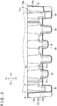
FIG. 2 is a front view depicting the pulp mold cushioning material, as viewed in the direction indicated by arrow II inFIG. 1 ; -
FIG. 3 is a sectional view taken along line III-III ofFIG. 2 ; -
FIG. 4A is a sectional view taken along line IVa-IVa ofFIG. 2 ; -
FIG. 4B is a sectional view taken along line IVb-IVb ofFIG. 2 ; -
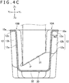
FIG. 4C is a sectional view taken along line IVc-IVc ofFIG. 2 ; -
FIG. 5 is an enlarged view of a region V inFIG. 4B ; -
FIG. 6A is an enlarged view ofFIG. 1 ; -
FIG. 6B is a perspective view of the part illustrated inFIG. 6A , as viewed from another angle; and -
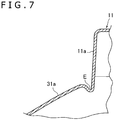
FIG. 7 is a sectional view taken along line VII-VII ofFIG. 2 . - An example of an embodiment of the pulp mold cushioning material proposed in the present disclosure will be described below. Herein, referring to
FIGS. 1 to 7 , a pulp mold cushioning material 1 as an example of the embodiment will be described. In the following, the pulp mold cushioning material 1 will be referred to simply as the cushioning material 1. - In the following description, Y1 and Y2 directions illustrated in
FIG. 1 and the like will be referred to respectively as the forward and rearward directions, X1 and X2 directions will be referred to respectively as the rightward and leftward directions, and Z1 and Z2 directions will be referred to respectively as the upward and downward directions. These directions are used for indicating the relative positional relations of components of the cushioning material 1, and do not define the posture of the cushioning material 1 during use. - As illustrated in
FIG. 1 , the cushioning material 1 has a box-like shape opening to the upper side. When the cushioning material 1 is in use, a body to be accommodated, P (seeFIG. 3 ), such as an electronic apparatus is disposed inside the cushioning material 1. In other words, the cushioning material 1 has inside thereof an accommodating space inside of which the body to be accommodated, P, is disposed. When the cushioning material 1 is in use, in a body to be accommodated, two cushioning materials 1, which face each other, are used. The body to be accommodated, P, is put in the accommodating box in the state in which the cushioning material 1 is fitted outside thereof. - The cushioning material 1 has a plurality of main walls defining the accommodating space. The cushioning material 1 has a
front wall 10A, arear wall 10B, aright wall 20A, aleft wall 20B, and abottom wall 30 as the main walls. Theright wall 20A is located on the right side of thewalls walls left wall 20B is located on the left side of thewalls walls bottom wall 30 is located at lower portions of thewalls - The cushioning material 1 is a molded product obtained using paper (for example, used paper) as a raw material, and the
walls walls walls - The shape of the cushioning material is not limited to that in the example of the cushioning material 1. The cushioning material 1 may have only part of the
walls front wall 10A, thebottom wall 30 and therear wall 10B, and may lack thewalls front wall 10A, theright wall 20A and thebottom wall 30. Such a cushioning material 1 is opening in the three directions (the upward, forward and leftward directions), and can be mounted to a corner of the body to be accommodated, P. In the cushioning material 1, the length of thefront wall 10A and therear wall 10B in the left-right direction is greater than the length of theright wall 20A and theleft wall 20B in the front-rear direction. The length of thefront wall 10A and therear wall 10B in the left-right direction may be equal to, or may be smaller than, the length of theright wall 20A and theleft wall 20B in the front-rear direction, unlike in the cushioning material 1. - As depicted in
FIG. 1 , thefront wall 10A is formed with a plurality of projectingportions portion 11 has aninner wall portion 11a (seeFIG. 4A ) of the first projectingportion 11 that is oriented toward the inside of the accommodating space and that extends upward from thebottom wall 30. The second projectingportion 12 has aninner wall portion 12a (seeFIG. 4C ) of the second projectingportion 12 that is oriented toward the inside of the accommodating space and that extends upward from thebottom wall 30. The projectingportions front wall 10A has outer wall portions 13 (seeFIG. 4B ) extending upward from thebottom wall 30, between two adjacent projectingportions outer wall portion 13 is formed between two adjacentinner wall portions inner walls 11a and between theinner wall portion 11a and theinner wall portion 12a adjacent to each other). Theinner wall portions outer wall portions 13. In other words, theinner wall portions front wall 10A are located more to the rear side than theouter wall portions 13. - As illustrated in
FIGS. 4A and4C , theinner wall portion 11a of the first projectingportion 11 projects more largely to the inside of the accommodating space than theinner wall portion 12a of the second projectingportion 12. In thefront wall 10A, theinner wall portion 11a of the first projectingportion 11 is located more to the rear side than theinner wall portion 12a of the second projectingportion 12. Therefore, the position of theinner wall portion 12a in the front-rear direction is between the position of theinner wall portion 11a and the position of theouter wall portion 13 in the front-rear direction. When the cushioning material 1 is in use, thefront wall 10A supports the body to be accommodated, P, by theinner wall portion 11a of the first projectingportion 11. In a state in which the first projectingportions 11 are not deformed, theinner wall portions 12a of the second projectingportions 12 do not make contact with the body to be accommodated, P. With thefront wall 10A thus formed with the two kinds of projectingportions front wall 10A is formed with three first projectingportions 11 and three second projectingportions 12. The numbers of the projectingportions - In the example of the cushioning material 1, the width of the first projecting
portion 11 in the left-right direction is substantially the same as the width of the second projectingportion 12 in the left-right direction; however, the relation between the widths is not limited to that in the example of the cushioning material 1. In addition, theouter wall portion 13 is substantially the same as the projectingportions - The projecting
portions side wall portions FIG. 6A ) that extend forward from left and right ends of theinner wall portions outer wall portion 13, respectively. In addition, the projectingportions end wall portions inner wall portions front wall 10A can enhance more the rigidity of thefront wall 10A. Note that the height of the upperend wall portions upper edge 10a (seeFIGS. 4A and4C ) of thefront wall 10A. - The
rear wall 10B of the cushioning material 1 has the same structure as that of thefront wall 10A. Thus, therear wall 10B has the projectingportions outer wall portion 13 described above. In the example of the cushioning material 1, the positions of the projectingportions rear wall 10B in the left-right direction coincide with the positions of the projectingportions front wall 10A in the left-right direction. The projectingportions rear wall 10B may be deviated from the projectingportions front wall 10A in the left-right direction, unlike in the cushioning material 1. - The structure of the
front wall 10A and therear wall 10B is not limited to that in the example of the cushioning material 1. For instance, the positions of theinner wall portions 12a of the second projectingportions 12 in the front-rear direction may be the same as those of theinner wall portions 11a of the first projectingportions 11. In other words, thefront wall 10A and therear wall 10B may each have only one kind of projecting portions. Unlike this, thefront wall 10A and therear wall 10B may have three kinds of projecting portions that differ in the size of inward projection. In a further example, the projectingportions upper edge 10a of thefront wall 10A. In other words, the upperend wall portions upper edge 10a of thefront wall 10A. In a further example, thefront wall 10A and therear wall 10B may not be the same in structure. - As depicted in
FIG. 1 , theright wall 20A also is formed with projectingportions 21 projecting toward the inside of the accommodating space (projecting toward the left side). Theright wall 20A is formed with two projectingportions 21, which are aligned in the front-rear direction. The number of the projectingportions 21 formed in theright wall 20A is not limited to that in the example of the cushioning material 1. The number of the projectingportions 21 may be, for example, one or may be three or more. The projectingportion 21 has aninner wall portion 21a (seeFIG. 3 ) that is oriented to the inside of the accommodating space and that extends upward from thebottom wall 30. In addition, theright wall 20A has a plurality of outer wall portions 23 (seeFIG. 3 ) extending upward from thebottom wall 30. Theinner wall portions 21a and theouter wall portions 23 of the projectingportions 21 are alternately aligned in the front-rear direction. In other words, oneouter wall portion 23 is formed between the twoinner wall portions 21a. Theinner wall portions 21a project more to the inside of the accommodating space than theouter wall portions 23. In other words, theinner wall portions 21a formed in theright wall 20A are located more to the left side than theouter wall portions 23. Such a structure of theright wall 20A can enhance the rigidity of theright wall 20A. The projection width of the projectingportions 21 is, for example, greater than four times a thickness T1 (seeFIG. 5 ) of the cushioning material 1, like the projectingportions front wall 10A described above. When the cushioning material 1 is in use, theright wall 20A supports the body to be accommodated, P, by theinner wall portions 21a. - The projecting
portions 21 of the right wall 20 are columnar in shape, and each haveside wall portions 21b (seeFIG. 6A ) that extend rightward from front end rear edges of theinner wall portion 21a and that are connected to theouter wall portion 23. The projectingportion 21 has an upperend wall portion 21c (seeFIG. 6A ) extending rightward from an upper edge of theinner wall portion 21a. The upperend wall portions 21c can enhance the rigidity of theright wall 20A. The height of the upperend wall portions 21c coincides with the height of an upper edge of theright wall 20A. - As illustrated in
FIG. 1 , theleft wall 20B has a projectingportion 22 andouter wall portions 23. The projectingportion 22 projects to the inside of the accommodating space, like the projectingportions 21 of theright wall 20A. The number of the projectingportion 22 in theleft wall 20B is one, unlike in theright wall 20A. Therefore, one projectingportion 22 is formed between twoouter wall portions 23. The number of the projectingportions 22 may be more than one, unlike in the example of the cushioning material 1. The projectingportion 22 also has aninner wall portion 22a (seeFIG. 3 ) extending upward from thebottom wall 30, and an upperend wall portion 22c (seeFIG. 3 ) extending leftward from an upper edge of theinner wall portion 22a. The height of the upperend wall portion 22c coincides with the height of an upper edge of theleft wall 20B. The structure of theleft wall 20B may be the same as that of theright wall 20A, unlike in the example of the cushioning material 1. - In a cushioning material in the past, a flange (for example, a flange N indicated by alternate long and two short dashes line in
FIG. 4B ) is provided at an edge of an opening of the cushioning material. The flange is a part that spreads from the edge of the opening of the cushioning material to the outside of the cushioning material and that extends along the edge of the opening. The flange is formed along the whole circumference of the opening. On the other hand, the cushioning material 1 proposed in the present disclosure does not have a flange at the edge of the opening. - Specifically, as depicted in
FIG. 4B , thefront wall 10A and therear wall 10B do not have, at theirupper edge 10a, a portion extending to the outside of the cushioning material 1 beyond the position of theouter wall portion 13. In other words, thefront wall 10A does not have a part extending forward beyond the position of theouter wall portion 13. In addition, therear wall 10B does not have a part extending rearward beyond the position of theouter wall portion 13. - Therefore, in the
front wall 10A, theouter wall portions 13 are located at the frontmost positions, and, in therear wall 10B, theouter wall portions 13 are located at the rearmost positions. In the example of the cushioning material 1, theouter wall portions 13 are slightly inclined toward the outside in relation to the vertical direction. For this reason, in thefront wall 10A, the upper edges of the outer wall portions 13 (theupper edge 10a of thefront wall 10A) are located at the frontmost positions, and, in therear wall 10B, the upper edges of the outer wall portions 13 (theupper edge 10a of therear wall 10B) are located at the rearmost positions. Therefore, when the cushioning material 1 is in use, theouter wall portions 13 themselves (inclusive of the upper edges of the outer wall portions 13) make contact with the inner surface of the accommodating box. - According to such a cushioning material 1, the size of the accommodating box for accommodating the body to be accommodated, P, can be reduced, resulting in that transport efficiency of the body to be accommodated, P, can be enhanced. Note that the
front wall 10A and therear wall 10B are formed with the aforementioned projectingportions - Since the
front wall 10A and therear wall 10B thus do not have a flange, the upperend wall portions 11c of the two projectingportions 11 aligned in the left-right direction with theouter wall portion 13 therebetween are connected to each other through an upper edge of the outer wall portion 13 (part of theupper edge 10a). In other words, in the case where thefront wall 10A and therear wall 10B have flanges at theupper edges 10a, the upperend wall portions 11c of the two projectingportions 11 aligned in the left-right direction are connected to each other through the upper edge of theouter wall portion 13 and the flanges. However, in the cushioning material 1, since thefront wall 10A and therear wall 10B are not formed with a flange at theupper edges 10a, the upperend wall portions 11c of the two projectingportions 11 are connected with each other through only the upper edge of theouter wall portion 13. Thefront wall 10A has theouter wall portion 13 located between the first projectingportion 11 and the second projectingportion 12. The upperend wall portions portions outer wall portion 13. Thefront wall 10A may have anouter wall portion 13 located between two second projectingportions 12. Besides, the upperend wall portions 12c of the two projectingportions 12 may be connected to each other through only the upper edge of theouter wall portion 13. - Note that the upper edge of the
outer wall portion 13 is that part of theupper edge 10a (or an end portion of material of the cushioning material 1) which includes theouter wall portion 13. As will be described later, as theouter wall portion 13 is viewed in a direction (arrow D, seeFIG. 5 ) along theouter wall portion 13, a thickness (T2, seeFIG. 5 ) of the upper edge of theouter wall portion 13 is substantially the same with the thickness (T1) of theouter wall portion 13. Therefore, the cushioning material 1 does not have a part connected to the upper edge of theouter wall portion 13, in section of theouter wall portion 13. In the case where thefront wall 10A and therear wall 10B have flanges, the edge of the opening (the opening that opens to the upper side) is present at a position spaced by the width of the flange from the edge (the edge of the flange) of theouter wall portion 13. In the cushioning material 1, however, since thefront wall 10A and therear wall 10B do not have a flange, the upper edge of theouter wall portion 13 constitutes part of the edge of the opening (the opening that opens to the upper side) of the cushioning material 1. - Note that the edges of the upper
end wall portions portions 11 and 12 (the edges located on the side opposite to theinner wall portions outer wall portions 13 toward the outside of the cushioning material 1. In the example of the cushioning material 1, the positions of the edges of the upperend wall portions outer wall portions 13. In other words, theupper edge 10a of thefront wall 10A is formed rectilinearly along the left-right direction. The edges of the upperend wall portions outer wall portions 13 are aligned in the left-right direction, and constitute theupper edge 10a. - Although the
front wall 10A is not formed with a flange at theupper edge 10a thereof, theupper edge 10a is slightly curved to the front side, as depicted inFIG. 5 . The thickness T2 of theupper edge 10a obtained as theouter wall portion 13 is viewed in the direction along the outer wall portion 13 (the direction indicated by arrow D inFIG. 5 ) is greater than the thickness (the thickness of the outer wall portion 13) T1 of thefront wall 10A, but is smaller than two times the thickness T1. Preferably, the thickness T2 is not more than 1.5 times the thickness T1. In other words, the thickness T2 and the thickness T1 are substantially the same. - As aforementioned, the
front wall 10A is formed with the projectingportions FIGS. 4A and4C ) of the projectingportions FIG. 5 ) of theupper edge 10a of thefront wall 10A. Preferably, the projection widths W1 and W2 are greater than four times the thickness T2 of theupper edge 10a of thefront wall 10A. More preferably, the projection widths W1 and W2 are greater than five times the thickness T2 of theedge 10a of the cushioning material 1. In the example of the cushioning material 1, the projection width W1 of the projectingportion 11 is greater than, for example, six times the thickness T2 of theedge 10a of the cushioning material 1. Since the projection widths are thus comparatively large, high cushioning performance can be secured, and the rigidity of thefront wall 10A can be secured notwithstanding a flange is not formed at theedge 10a. The projection widths W1 and W2 of the projectingportions - As depicted in
FIG. 3 , theright wall 20A also does not have a flange. Thus, theright wall 20A does not have, at theupper edge 20a thereof, a part extending to the outside of the cushioning material 1 beyond the positions of the outer wall portions 23 (in other words, a part extending rightward beyond the positions of the outer wall portions 23). Therefore, in theright wall 20A, theouter wall portions 23 are located at the rightmost positions. - The
outer wall portions 23 are inclined toward the outside of the cushioning material 1 (toward the right side). Therefore, in theright wall 20A, upper edges of the outer wall portions 23 (theupper edge 20a of theright wall 20A) are located at the rightmost positions. As a result, when the cushioning material 1 is in use, the outer wall portions 23 (inclusive of the upper edges of the outer wall portions 23) make contact with the inner surface of the accommodating box. Note that as illustrated inFIG. 6A , a right edge of an upperend wall portion 21c of the projectingportion 21 does not come beyond the position of theouter wall portion 23, and theupper edge 20a of theright wall 20A is formed rectilinearly along the front-rear direction. - Since the
right wall 20A thus does not have a flange, the upperend wall portions 21c of the two projectingportions 21 aligned in the front-rear direction with theouter wall portion 23 therebetween are connected to each other through the upper edge of the outer wall portion 23 (part of theupper edge 20a). In other words, in the case where theright wall 20A has a flange at theupper edge 20a, the upperend wall portions 21c of the two projectingportions 21 aligned in the front-rear direction are connected to each other through the upper edge of theouter wall portion 23 and the flange. However, in the cushioning material 1, since theright wall 20A is not formed with a flange at theupper edge 20a, the upperend wall portions 21c of the two projectingportions 21 are connected to each other through only the upper edge of theouter wall portion 23. - The upper edge of the
outer wall portion 23 is part of theupper edge 20a (or an end portion of material of the cushioning material 1) of theright wall 20A. Therefore, the cushioning material 1 does not have a part connected to the upper edge of theouter wall portion 23, in section of theouter wall portion 23. In the case where theright wall 20A has a flange, the edge of the opening (the opening that opens to the upper side) of the cushioning material 1 is present at a position spaced by the width of the flange from the edge of the outer wall portion 23 (the edge of the flange). However, in the cushioning material 1, since theright wall 20A does not have a flange, the upper edge of theouter wall portion 23 constitutes part of the edge of the opening (the opening that opens to the upper side) of the cushioning material 1. - In addition, similarly to the thicknesses T1 and T2 of the
front wall 10A described referring toFIG. 5 , the thickness of theupper edge 20a of theright wall 20A obtained as theouter wall portion 23 is viewed in a direction along theouter wall portion 23 is smaller than two times the thickness of theright wall 20A (the thickness of the outer wall portion 23). Preferably, the thickness of theupper edge 20a is not more than 1.5 times the thickness of theright wall 20A (the thickness of the outer wall portion 23). In addition, the projection width of the projectingportion 21 is greater than, for example, three times the thickness of theupper edge 20a of theright wall 20A. Preferably, the projection width is greater than four times the thickness of theupper edge 20a of theright wall 20A. - The
left wall 20B also does not have a flange, like theright wall 20A. In other words, theleft wall 20B does not have a part extending to the outside of the cushioning material 1 (a part extending leftward) beyond the positions of theouter wall portions 23. - Thus, in the cushioning material 1, the four
walls upper edges front wall 10A and therear wall 10B are not formed with a flange but theright wall 20A and theleft wall 20B are formed with flanges, unlike the example of the cushioning material 1. - As illustrated in
FIG. 3 , thebottom wall 30 also is formed with projectingportions 31 projecting toward the inside of the accommodating space (projecting upward). As depicted inFIG. 3 , the projectingportions 31 are aligned at intervals in the left-right directions. Thebottom wall 30 has lower wall portions (outer wall portions) 32 and 33 which are each located between the two adjacent projectingportions 31. The projectingportions 31 have higher wall portions (inner wall portions) 31a located at positions higher than thelower wall portions higher wall portions 31a are located more to the inside of the accommodating space than thelower wall portions higher wall portions 31a and thelower wall portions lower wall portion 32 or thelower wall portion 33 is formed between the two adjacenthigher wall portions 31a. This structure enhances the rigidity of thebottom wall 30, resulting in that high rigidity of the cushioning material 1 is secured, notwithstanding the cushioning material 1 is not formed with a flange at the edge of the opening. - As illustrated in
FIG. 3 , thelower wall portions 32 are located at positions higher than thelower wall portions 33. In other words, thelower wall portions 32 are located more to the inside of the accommodating space than thelower wall portions 33. The positions of thelower wall portions 32 in the vertical direction are lower than those of thehigher wall portions 31a. When the cushioning material 1 is in use, the body to be accommodated, P, is supported by thehigher wall portions 31a. In addition, thelower wall portions 33 make contact with the inner surface of the accommodating box, whereas thelower wall portions 32 do not make contact with the inner surface of the accommodating box in a state in which thelower wall portions 33 are not deformed. This makes it possible to restrain excessively large forces from acting on the body to be accommodated, P, as compared to the structure in which, for example, all thelower wall portions - As depicted in
FIG. 4B , thehigher wall portion 31a of the projectingportion 31 continues from thefront wall 10A to therear wall 10B. More specifically, thehigher wall portion 31a of the projectingportion 31 continues from theouter wall portion 13 of thefront wall 10A to theouter wall portion 13 of therear wall 10B. In the example of the cushioning material 1, thehigher wall portion 31a of the projectingportion 31 has aninclined surface 31e conforming to the external shape of the body to be accommodated, P. Theinclined surface 31e is inclined such as to become higher in going from the rear side toward the front side. Thehigher wall portion 31a hashorizontal portions 31f on the front side and the rear side of theinclined surface 31e. Thehigher wall portion 31a may not have such aninclined surface 31e, unlike in the example of the cushioning material 1. In other words, thehigher wall portion 31a may be formed horizontally. In a further example, thebottom wall 30 may not have the two kinds oflower wall portions - Note that as illustrated in
FIG. 4A , alower wall portion 33 is formed between aninner wall portion 11a of the first projectingportion 11 of thefront wall 10A and aninner wall portion 11a of the first projectingportion 11 of therear wall 10B. In addition, as depicted inFIG. 4A , alower wall portion 33 is formed between aninner wall portion 11a of the first projectingportion 11 of thefront wall 10A and aninner wall portion 11a of the first projectingportion 11 of therear wall 10B. - As aforementioned, when the cushioning material 1 is in use, the body to be accommodated, P, is supported by the
higher wall portions 31a of thebottom wall 30 and theinner wall portions 11a of the first projectingportions 11 of thefront wall 10A and therear wall 10B. As depicted inFIGS. 6A and6B , thehigher wall portions 31a are connected to theinner wall portions 11a. Besides, a recess E is formed in a connection portion between thehigher wall portion 31a and theinner wall portion 11a. Therefore, when the cushioning material 1 is in use, the body to be accommodated, P, does not make contact with the connection portions between thehigher wall portions 31a and theinner wall portions 11a. This makes it possible to restrain excessively large forces from acting on the edges of the body to be accommodated, P. - In the example of the cushioning material 1, the
higher wall portion 31a is formed between theouter wall portion 13 of thefront wall 10A and theouter wall portion 13 of therear wall 10B, and the positions of thehigher wall portions 31a and the positions of theinner wall portions 11a of thewalls higher wall portion 31a and an edge 31g (an edge located at an end portion in the left-right direction) of theinner wall portion 11a are connected with each other. The recess E is formed in the connection portion (boundary) between them. - Note that a hole penetrating the cushioning material 1 may be formed in place of the recess E, in the connection portion between the
higher wall portion 31a and theinner wall portion 11a. In addition, the positions of thehigher wall portions 31a and the positions of theinner wall portions 11a may not be deviated from each other in the left-right direction. In this case, also, a groove may be formed as an example of the recess E, in the connection portion between thehigher wall portion 31a and theinner wall portion 11a. - As has been described above, the cushioning material 1 opens to the upper side, and the
front wall 10A has theouter wall portions 13 and theinner wall portions outer wall portions 13. Thefront wall 10A does not have a flange at theupper edge 10a thereof. According to this structure, transport efficiency of goods can be enhanced, while restraining a lowering in the rigidity of the pulp mold cushioning material. - In addition, the
front wall 10A has theouter wall portions 13 and theinner wall portions outer wall portions 13, and theouter wall portions 13 and theinner wall portions bottom wall 30 has thelower wall portions higher wall portions 31a projecting more to the inside of the accommodating space than thelower wall portions lower wall portions higher wall portions 31a are aligned in the left-right direction. The recess E is formed in the connection portion between theouter wall portion 13 of thefront wall 10A and thehigher wall portion 31a of thebottom wall 30. According to this structure, it is possible to restrain large forces from acting on the corners of the body to be accommodated, P. - The pulp mold cushioning material proposed in the present disclosure is not limited to the aforementioned cushioning material 1, and various modifications are possible. For instance, as aforementioned, the size and shape of the cushioning material 1 may be changed as required. For example, the cushioning material 1 may have only the
front wall 10A, thebottom wall 30 and therear wall 10B, and may lack thewalls front wall 10A, theright wall 20A and thebottom wall 30. - The present disclosure contains subject matter related to that disclosed in Japanese Priority Patent Application
JP 2018-076808 - It should be understood by those skilled in the art that various modifications, combinations, sub-combinations and alterations may occur depending on design requirements and other factors insofar as they are within the scope of the appended claims or the equivalents thereof.
Claims (13)
- A pulp mold cushioning material having a plurality of main walls which define an accommodating space for accommodating inside thereof a body to be accommodated and which each have an opening that opens in a first direction,
wherein the plurality of main walls include a first main wall,
the first main wall includes a first outer wall portion and a first inner wall portion that projects more to inside of the accommodating space than the first outer wall portion, the first outer wall portion and the first inner wall portion being aligned in a second direction orthogonal to the first direction,
the first main wall has an edge portion extending in the second direction, at an end portion of the first main wall in the first direction, and
the first main wall does not have a flange at the edge portion. - A pulp mold cushioning material having a plurality of main walls which define an accommodating space for accommodating inside thereof a body to be accommodated and which have an opening that opens in a first direction,
wherein the plurality of main walls include a first main wall,
the first main wall includes a first outer wall portion and at least two first projecting portions having first inner wall portions projecting more to inside of the accommodating space than a position of the first outer wall portion,
the first outer wall portion is located between the at least two first projecting portions and is aligned with the at least two first projecting portions in a second direction orthogonal to the first direction,
the first outer wall portion has a first edge portion which is located at an end portion of the outer wall portion in the first direction and which is part of an edge of the opening,
each of the at least two first projecting portions has an end wall portion located at an end portion of the first inner wall portion in the first direction, and
the end wall portions of the at least two first projecting portions are connected to each other through the first edge portion of the first outer wall portion. - The pulp mold cushioning material according to claim 1,
wherein a thickness of the edge portion as the first main wall is viewed in a direction along the first main wall is smaller than 2.0 times a thickness of the first outer wall portion. - The pulp mold cushioning material according to claim 1,
wherein the first main wall has a first projecting portion that has the first inner wall portion and that projects more to inside of the accommodating space than the first outer wall portion, and
a projection width of the first projecting portion is greater than three times a thickness of the edge portion as the first main wall is viewed in a direction along the first main wall. - The pulp mold cushioning material according to claim 1 or claim 2,
wherein the plurality of main walls include a second main wall that is located on a side opposite to the first direction with respect to the first main wall and that is connected to the first main wall,
the second main wall includes a second outer wall portion and a second inner wall portion that projects more to inside of the accommodating space than the second outer wall portion, and
the second outer wall portion and the second inner wall portion are aligned in the second direction. - The pulp mold cushioning material according to claim 1 or claim 2,
wherein the plurality of main walls include a third main wall that is located in the second direction with respect to the first main wall and that is connected to the first main wall,
the third main wall has an edge portion extending in a third direction orthogonal to both the first direction and the second direction, at an end portion of the third main wall in the first direction, and
the third main wall does not have a flange at the edge portion. - The pulp mold cushioning material according to claim 1 or claim 2,
wherein the plurality of main walls have an opening edge that includes the edge portion of the first main wall and that opens in the first direction, and
the opening edge does not have a flange along a whole circumference of the opening edge. - The pulp mold cushioning material according to claim 1,
wherein the first main wall has a first projecting portion that projects to inside of the accommodating space and that has the first inner wall portion, and
the first projecting portion has an end wall portion extending from the first inner wall portion to outside of the accommodating space. - The pulp mold cushioning material according to claim 5,
wherein a connection portion between the first inner wall portion and the second inner wall portion is formed with at least one of a recess and a hole. - The pulp mold cushioning material according to claim 1 or claim 2,
wherein the first main wall has a (1-1)th inner wall portion and a (1-2)th inner wall portion located more to inside of the accommodating space than the (1-1)th inner wall portion, as the first inner wall portion. - The pulp mold cushioning material according to claim 2,
wherein the end wall portions of the at least two first projecting portions extend from the first inner wall portion in a third direction orthogonal to both the first direction and the second direction,
the end wall portions have an edge portion located at an end portion in the third direction, and
the edge portions of the end wall portions are aligned with the edge portion of the outer wall portion in the second direction. - A pulp mold cushioning material comprising:an accommodating space which opens in a first direction and inside of which a body to be accommodated is disposed; anda plurality of main walls that define the accommodating space,wherein the plurality of main walls include a first main wall and a second main wall that is located in a direction opposite to the first direction with respect to the first main wall and that is connected to the first main wall,the first main wall has a first outer wall portion and a first inner wall portion that projects more to inside of the accommodating space than the first outer wall portion, the first outer wall portion and the first inner wall portion being aligned in a second direction orthogonal to the first direction,the second main wall has a second outer wall portion and a second inner wall portion that projects more to inside of the accommodating space than the second outer wall portion, the second outer wall portion and the second inner wall portion being aligned in the second direction, anda connection portion between the first inner wall portion and the second inner wall portion is formed with a recess or a hole.
- The pulp mold cushioning material according to claim 10,
wherein a position of the first inner wall portion and a position of the second inner wall portion are deviated from each other in the second direction, and the recess or the hole is formed between an edge of the first inner wall portion and an edge of the second inner wall portion.
Applications Claiming Priority (1)
| Application Number | Priority Date | Filing Date | Title |
|---|---|---|---|
| JP2018076808A JP6736598B2 (en) | 2018-04-12 | 2018-04-12 | Pulp mold cushioning material |
Publications (2)
| Publication Number | Publication Date |
|---|---|
| EP3552985A2 true EP3552985A2 (en) | 2019-10-16 |
| EP3552985A3 EP3552985A3 (en) | 2019-12-11 |
Family
ID=66101834
Family Applications (1)
| Application Number | Title | Priority Date | Filing Date |
|---|---|---|---|
| EP19166981.1A Pending EP3552985A3 (en) | 2018-04-12 | 2019-04-03 | Pulp mold cushioning material |
Country Status (3)
| Country | Link |
|---|---|
| EP (1) | EP3552985A3 (en) |
| JP (1) | JP6736598B2 (en) |
| CN (1) | CN210972276U (en) |
Families Citing this family (2)
| Publication number | Priority date | Publication date | Assignee | Title |
|---|---|---|---|---|
| JP7721586B2 (en) | 2023-02-21 | 2025-08-12 | 株式会社ソニー・インタラクティブエンタテインメント | Molded pulp cushioning material |
| WO2025243955A1 (en) * | 2024-05-24 | 2025-11-27 | 株式会社ソニー・インタラクティブエンタテインメント | Pulp mold cushioning material |
Citations (2)
| Publication number | Priority date | Publication date | Assignee | Title |
|---|---|---|---|---|
| JP2001146700A (en) | 1999-11-22 | 2001-05-29 | Sony Corp | Mold for pulp mold cushion, method for producing pulp mold cushion, and pulp mold cushion |
| JP2018076808A (en) | 2016-11-09 | 2018-05-17 | 荻野工業株式会社 | Oil jet device |
Family Cites Families (3)
| Publication number | Priority date | Publication date | Assignee | Title |
|---|---|---|---|---|
| US5532044A (en) * | 1994-12-06 | 1996-07-02 | Jen; Hsieh C. | Foldable pulp molded cushioning material |
| JP2000281140A (en) * | 1999-03-29 | 2000-10-10 | Toshiba Tec Corp | Product packaging shock absorber |
| US8757384B2 (en) * | 2010-11-03 | 2014-06-24 | Dell Products, Lp. | Devices and methods for packing |
-
2018
- 2018-04-12 JP JP2018076808A patent/JP6736598B2/en active Active
-
2019
- 2019-04-03 EP EP19166981.1A patent/EP3552985A3/en active Pending
- 2019-04-04 CN CN201920456955.6U patent/CN210972276U/en active Active
Patent Citations (2)
| Publication number | Priority date | Publication date | Assignee | Title |
|---|---|---|---|---|
| JP2001146700A (en) | 1999-11-22 | 2001-05-29 | Sony Corp | Mold for pulp mold cushion, method for producing pulp mold cushion, and pulp mold cushion |
| JP2018076808A (en) | 2016-11-09 | 2018-05-17 | 荻野工業株式会社 | Oil jet device |
Also Published As
| Publication number | Publication date |
|---|---|
| JP2019182499A (en) | 2019-10-24 |
| CN210972276U (en) | 2020-07-10 |
| JP6736598B2 (en) | 2020-08-05 |
| EP3552985A3 (en) | 2019-12-11 |
Similar Documents
| Publication | Publication Date | Title |
|---|---|---|
| US11279544B2 (en) | Container | |
| CN201128567Y (en) | Plate body packing box | |
| KR20240122710A (en) | Printed circuit board unit | |
| EP3552985A2 (en) | Pulp mold cushioning material | |
| CN101670918A (en) | packaging structure | |
| CN109415160B (en) | storage container | |
| JP6135423B2 (en) | Tray-type packaging box | |
| US20200189825A1 (en) | Container | |
| USD1050059S1 (en) | Circuit board for computer printers | |
| TWM534734U (en) | Packaging buffer article | |
| CN205470653U (en) | Packing timber and packing body | |
| KR200490607Y1 (en) | Panel transport container | |
| CN104386359A (en) | Substrate packaging structure and substrate packaging structure set | |
| CN107000585A (en) | The vehicle body mounting configuration of fuel tank | |
| KR101934963B1 (en) | A Tray for Planar Parts | |
| US7646360B2 (en) | Plasma display apparatus and method of manufacturing chassis base used therefor | |
| KR102356344B1 (en) | A Tray for Planar Parts | |
| US12577028B2 (en) | Molded pulp cushioning material | |
| CN205602405U (en) | Display device's bale structure | |
| CN103979207A (en) | Package buffering structure | |
| JP7338207B2 (en) | image forming device | |
| JP2010116209A5 (en) | ||
| CN210192317U (en) | Packaging assembly of semiconductor laser module | |
| JP3205028U (en) | Portable storage case | |
| CN203529096U (en) | Sealing piece container |
Legal Events
| Date | Code | Title | Description |
|---|---|---|---|
| PUAI | Public reference made under article 153(3) epc to a published international application that has entered the european phase |
Free format text: ORIGINAL CODE: 0009012 |
|
| STAA | Information on the status of an ep patent application or granted ep patent |
Free format text: STATUS: REQUEST FOR EXAMINATION WAS MADE |
|
| 17P | Request for examination filed |
Effective date: 20190501 |
|
| AK | Designated contracting states |
Kind code of ref document: A2 Designated state(s): AL AT BE BG CH CY CZ DE DK EE ES FI FR GB GR HR HU IE IS IT LI LT LU LV MC MK MT NL NO PL PT RO RS SE SI SK SM TR |
|
| AX | Request for extension of the european patent |
Extension state: BA ME |
|
| PUAL | Search report despatched |
Free format text: ORIGINAL CODE: 0009013 |
|
| AK | Designated contracting states |
Kind code of ref document: A3 Designated state(s): AL AT BE BG CH CY CZ DE DK EE ES FI FR GB GR HR HU IE IS IT LI LT LU LV MC MK MT NL NO PL PT RO RS SE SI SK SM TR |
|
| AX | Request for extension of the european patent |
Extension state: BA ME |
|
| RIC1 | Information provided on ipc code assigned before grant |
Ipc: B65D 81/05 20060101AFI20191107BHEP Ipc: B65D 81/133 20060101ALI20191107BHEP Ipc: B65D 5/50 20060101ALI20191107BHEP |
|
| STAA | Information on the status of an ep patent application or granted ep patent |
Free format text: STATUS: EXAMINATION IS IN PROGRESS |
|
| 17Q | First examination report despatched |
Effective date: 20210119 |