EP3553254A1 - Modulare struktur - Google Patents
Modulare struktur Download PDFInfo
- Publication number
- EP3553254A1 EP3553254A1 EP18166923.5A EP18166923A EP3553254A1 EP 3553254 A1 EP3553254 A1 EP 3553254A1 EP 18166923 A EP18166923 A EP 18166923A EP 3553254 A1 EP3553254 A1 EP 3553254A1
- Authority
- EP
- European Patent Office
- Prior art keywords
- modular structure
- construction module
- construction
- modules
- sidewalls
- Prior art date
- Legal status (The legal status is an assumption and is not a legal conclusion. Google has not performed a legal analysis and makes no representation as to the accuracy of the status listed.)
- Withdrawn
Links
- 238000010276 construction Methods 0.000 claims abstract description 123
- 238000005304 joining Methods 0.000 claims description 39
- 239000000945 filler Substances 0.000 claims description 15
- 239000000463 material Substances 0.000 claims description 11
- XLYOFNOQVPJJNP-UHFFFAOYSA-N water Substances O XLYOFNOQVPJJNP-UHFFFAOYSA-N 0.000 claims description 7
- 229920001903 high density polyethylene Polymers 0.000 claims description 6
- 239000004700 high-density polyethylene Substances 0.000 claims description 6
- 239000004033 plastic Substances 0.000 claims description 6
- 229920003023 plastic Polymers 0.000 claims description 6
- 239000004743 Polypropylene Substances 0.000 claims description 5
- 238000004891 communication Methods 0.000 claims description 5
- 229920000139 polyethylene terephthalate Polymers 0.000 claims description 5
- 239000005020 polyethylene terephthalate Substances 0.000 claims description 5
- -1 polypropylene Polymers 0.000 claims description 5
- 229920001155 polypropylene Polymers 0.000 claims description 5
- 238000007667 floating Methods 0.000 claims description 4
- 230000015572 biosynthetic process Effects 0.000 claims description 3
- 238000005755 formation reaction Methods 0.000 claims description 3
- 238000000034 method Methods 0.000 description 5
- 238000004519 manufacturing process Methods 0.000 description 3
- 238000009413 insulation Methods 0.000 description 2
- 238000007789 sealing Methods 0.000 description 2
- 239000007787 solid Substances 0.000 description 2
- 239000002028 Biomass Substances 0.000 description 1
- 241000195493 Cryptophyta Species 0.000 description 1
- 230000004308 accommodation Effects 0.000 description 1
- 239000000853 adhesive Substances 0.000 description 1
- 230000001070 adhesive effect Effects 0.000 description 1
- 239000002551 biofuel Substances 0.000 description 1
- 230000005465 channeling Effects 0.000 description 1
- 238000000576 coating method Methods 0.000 description 1
- 239000003086 colorant Substances 0.000 description 1
- 230000007123 defense Effects 0.000 description 1
- 230000001419 dependent effect Effects 0.000 description 1
- 229910003460 diamond Inorganic materials 0.000 description 1
- 239000010432 diamond Substances 0.000 description 1
- 239000010791 domestic waste Substances 0.000 description 1
- 230000000694 effects Effects 0.000 description 1
- 238000000605 extraction Methods 0.000 description 1
- 238000001125 extrusion Methods 0.000 description 1
- 238000009313 farming Methods 0.000 description 1
- 239000003501 hydroponics Substances 0.000 description 1
- 238000003780 insertion Methods 0.000 description 1
- 230000037431 insertion Effects 0.000 description 1
- 244000144972 livestock Species 0.000 description 1
- 230000007774 longterm Effects 0.000 description 1
- 239000002184 metal Substances 0.000 description 1
- 229920003052 natural elastomer Polymers 0.000 description 1
- 229920001194 natural rubber Polymers 0.000 description 1
- 239000011435 rock Substances 0.000 description 1
- 239000000565 sealant Substances 0.000 description 1
- 238000003860 storage Methods 0.000 description 1
- 229920003051 synthetic elastomer Polymers 0.000 description 1
- 239000005061 synthetic rubber Substances 0.000 description 1
- 125000000391 vinyl group Chemical group [H]C([*])=C([H])[H] 0.000 description 1
- 229920002554 vinyl polymer Polymers 0.000 description 1
Images




Classifications
-
- E—FIXED CONSTRUCTIONS
- E04—BUILDING
- E04H—BUILDINGS OR LIKE STRUCTURES FOR PARTICULAR PURPOSES; SWIMMING OR SPLASH BATHS OR POOLS; MASTS; FENCING; TENTS OR CANOPIES, IN GENERAL
- E04H1/00—Buildings or groups of buildings for dwelling or office purposes; General layout, e.g. modular co-ordination or staggered storeys
- E04H1/12—Small buildings or other erections for limited occupation, erected in the open air or arranged in buildings, e.g. kiosks, waiting shelters for bus stops or for filling stations, roofs for railway platforms, watchmen's huts or dressing cubicles
-
- B—PERFORMING OPERATIONS; TRANSPORTING
- B63—SHIPS OR OTHER WATERBORNE VESSELS; RELATED EQUIPMENT
- B63B—SHIPS OR OTHER WATERBORNE VESSELS; EQUIPMENT FOR SHIPPING
- B63B7/00—Collapsible, foldable, inflatable or like vessels
- B63B7/02—Collapsible, foldable, inflatable or like vessels comprising only rigid parts
- B63B7/04—Collapsible, foldable, inflatable or like vessels comprising only rigid parts sectionalised
-
- E—FIXED CONSTRUCTIONS
- E04—BUILDING
- E04B—GENERAL BUILDING CONSTRUCTIONS; WALLS, e.g. PARTITIONS; ROOFS; FLOORS; CEILINGS; INSULATION OR OTHER PROTECTION OF BUILDINGS
- E04B1/00—Constructions in general; Structures which are not restricted either to walls, e.g. partitions, or floors or ceilings or roofs
- E04B1/343—Structures characterised by movable, separable, or collapsible parts, e.g. for transport
- E04B1/34315—Structures characterised by movable, separable, or collapsible parts, e.g. for transport characterised by separable parts
- E04B1/34326—Structures characterised by movable, separable, or collapsible parts, e.g. for transport characterised by separable parts mainly constituted by longitudinal elements
-
- E—FIXED CONSTRUCTIONS
- E04—BUILDING
- E04B—GENERAL BUILDING CONSTRUCTIONS; WALLS, e.g. PARTITIONS; ROOFS; FLOORS; CEILINGS; INSULATION OR OTHER PROTECTION OF BUILDINGS
- E04B5/00—Floors; Floor construction with regard to insulation; Connections specially adapted therefor
- E04B5/02—Load-carrying floor structures formed substantially of prefabricated units
- E04B5/026—Load-carrying floor structures formed substantially of prefabricated units with beams or slabs of plastic
-
- E—FIXED CONSTRUCTIONS
- E04—BUILDING
- E04C—STRUCTURAL ELEMENTS; BUILDING MATERIALS
- E04C3/00—Structural elongated elements designed for load-supporting
- E04C3/02—Joists; Girders, trusses, or trusslike structures, e.g. prefabricated; Lintels; Transoms; Braces
- E04C3/28—Joists; Girders, trusses, or trusslike structures, e.g. prefabricated; Lintels; Transoms; Braces of materials not covered by groups E04C3/04 - E04C3/20
-
- E—FIXED CONSTRUCTIONS
- E04—BUILDING
- E04C—STRUCTURAL ELEMENTS; BUILDING MATERIALS
- E04C3/00—Structural elongated elements designed for load-supporting
- E04C3/30—Columns; Pillars; Struts
- E04C3/36—Columns; Pillars; Struts of materials not covered by groups E04C3/32 or E04C3/34; of a combination of two or more materials
-
- B—PERFORMING OPERATIONS; TRANSPORTING
- B63—SHIPS OR OTHER WATERBORNE VESSELS; RELATED EQUIPMENT
- B63B—SHIPS OR OTHER WATERBORNE VESSELS; EQUIPMENT FOR SHIPPING
- B63B75/00—Building or assembling floating offshore structures, e.g. semi-submersible platforms, SPAR platforms or wind turbine platforms
-
- E—FIXED CONSTRUCTIONS
- E01—CONSTRUCTION OF ROADS, RAILWAYS, OR BRIDGES
- E01D—CONSTRUCTION OF BRIDGES, ELEVATED ROADWAYS OR VIADUCTS; ASSEMBLY OF BRIDGES
- E01D15/00—Movable or portable bridges; Floating bridges
Definitions
- the present invention relates to modular structures, and particularly to modular structures for use as housing, assembled from modules which are inexpensive structural elements which may be easily produced from recycled materials.
- the present invention arises from an attempt to address the problem of providing low-cost temporary accommodation, for example for refugees and other displaced persons.
- the most common current solution to the problem is a tent, made from a single skin of flexible material such as canvas, supported by poles and guy ropes.
- a disadvantage of the tents is that they are unsuitable for medium to long-term use, and perform poorly in terms of thermal insulation to maintain the temperature within the tent at an acceptable level.
- the present invention seeks to provide a construction module, and a modular structure assembled from the construction module which is easily erected to form a dwelling or shelter, with improved robustness and thermal insulation properties.
- a modular structure including at least two construction modules.
- Each construction module is a hollow body of cuboid or rhombohedron shape with four side walls and open front sides, wherein at least one of the side walls includes an attachment slot extending longitudinally along the sidewalls.
- the attachment slot is opening into an enlarged cavity of constant cross-section in longitudinal direction of the side wall.
- the inventive modular structure includes a plurality of thin-walled construction modules, which are assembled easily to for example walls, a floor or a roof of housings by means of specific connecting members. More specifically, these connecting members include a longitudinal attachment slot at the outer surface of the construction module. The slot opens out inwardly the hollow construction module so as to form a longitudinal cavity of equal cross-section.
- the geometry and dimension of the cavity is set to be such that a rigid joining element introduced from an upper or lower end of the connecting member into the cavity cannot be pull out through the attachment slot.
- a cross-sectional plane surface of the interior space of the cavity may be of for example elliptic shape.
- the attachment slot preferably extends longitudinally along the centre of the sidewall. Since the attachment slots and cavities are an integral part of the connecting members, mounting of the modular structure is easy.
- the construction module is a body of (generally) cuboid or rhombohedron shape.
- a cuboid is a polyhedron bounded by six quadrilateral faces and a rhombohedron is a three-dimensional figure like a cuboid, except that four of its faces are not squares or rectangular but rhombi.
- the construction module has the shape of a right rectangular-sided prism or a right square-sided prism. Both front sides of the construction modules are open and the side walls form a common (one-pieced) circumferential wall.
- the modular structure is an affordable and general light construction and may be in particular useful in emergency cases for building temporary and semi-permanent shelter.
- the modular structure allows to easily adapting the internal architecture of the shelter, for example by setting of dividing walls.
- a shelter or housing based on the inventive modular structure shows improved noise reduction and thermal properties compared to tents.
- the modular structure may be further useful for pop up of small movable businesses.
- Another field of application may be smart farming indoor or outdoor, movable flora or fauna growing, and agriculture production systems, like vertical or horizontal hydroponics and aeroponics growing systems.
- the modular structure may be applicable for building marine engineering sea defense, water channels, and buoyant food production platforms. Further applications and advantages of the modular structure are:
- two opposite side walls of the hollow body each includes the attachment slot and the enlarged cavity. Therefore, the construction of a panel or wall is simplified by assembling a number of construction modules side-by-sides such that the slots are on adjacent side walls and introducing of a common joining element.
- three side walls of the hollow body each include the attachment slot and the enlarged cavity, which allows fixing of up to three construction modules to one construction module.
- the construction module may further be a one-piece body made of plastics material, in particular extruded high-density polyethylene (HDPE), polypropylene (PP) or polyethylene terephthalate (PET).
- HDPE high-density polyethylene
- PP polypropylene
- PET polyethylene terephthalate
- the sidewalls including the attachment slot are concave, i.e. these side walls are curving in or hollowed inward the interior space of the construction module.
- the engagement between the joining element and the cavities draws the sidewalls into a flat rather than concave configuration, so that pressure is exerted at the corners of the construction modules to bring them into a tight sealing engagement.
- the sidewalls of the construction module preferably have a wall thickness t of from 1 to 5 millimetres.
- the wall thickness at corners where adjacent sidewalls meet is reduced compared to the wall thickness in other parts of the construction module and/or the wall thickness at the edges of the slots is increased compared to the wall thickness in other parts of the construction module.
- the joining slots of adjacent sidewalls of two construction modules may be in alignment and the modular structure may then further include a joining element.
- the joining element comprises two locking elements joined by a bridging element, wherein the locking elements of the joining element are inserted into respective cavities of the adjacent sidewalls and the bridging element extends through the slots.
- the modular structure may further include a filler element, which comprises a locking part and a filler part having a flat external face.
- the filler element is inserted into a cavity of a construction module so that the filler part occupies the slot with the face being flush with the outer surface of the respective sidewall.
- the modular structure further includes an end plug for closing one or both open front sides of the construction module.
- the end plug may include an end plate and a skirt extending perpendicularly to the end plate and being shaped so as to correspond to the internal form and dimensions of the construction module.
- the skirt being formed with internal formations which are shaped and dimensioned so as to fit closely round the ends of the walls of the cavities of the construction module.
- the end plug may further include an air valve being in communication with an interior space of the construction module.
- a depression may be formed in the end plate to accommodate the air valve, which is in communication with the underside of the end plate by means of an opening formed in the base of the depression.
- An attachment button is preferably mounted centrally in the end plate.
- the attachment button has a stem and a head.
- the stem of the attachment button is dimensioned so as to be receivable in the slot of the sidewalls of a construction module and the button being shaped to be co-operable with the parts of an internal face of the cavity of the construction module.
- the stem may be circular in cross-section.
- Another aspect of the present invention refers to the use of the before mentioned modular structure for forming a dwelling or shelter, a floating or floatable structure, a raft, a pontoon, a bridge, a storing device for water, or a pipe for transporting water.
- the terms “upper” and “lower” are defined according to the z-axis.
- the upper cover is positioned at the upper part of the z-axis, whereas the lower cover is positioned at the lower part thereof.
- the sizes of elements may be exaggerated for clarity.
- the size or thickness of each element may be arbitrarily shown for illustrative purposes, and thus the embodiments of the present invention should not be construed as being limited thereto.
- Construction modules according to the present invention, and structures formed therefrom will now be described with reference to the Figures.
- the construction elements are generally elongate, and are joined side-by-side to form panels which may then be used to form walls, floors and roofs of shelters.
- the construction module 1 is an elongate, hollow, generally square-section component.
- the module has four side walls 2, 3, 4 and 5.
- the sidewalls 2, 3 and 4 are generally concave, while the side wall 5 is generally planar.
- Three attachment slots 6 extend longitudinally along the centres of the sidewalls 2, 3 and 4, respectively. Internally of the construction module, each attachment slot 6 opens into an enlarged cavity 6a of generally elliptical cross-section, running along the length of the construction module 1.
- the construction module 1 is preferably formed by extrusion from a plastics material such as high-density polyethylene (HDPE), but may be formed from other suitable plastics materials such as polypropylene or PET.
- the plastics material may be opaque, translucent or transparent, and may be coloured.
- the generally square cross-section construction module of Figure 1 may have sidewalls of approximately 22 centimetres in width, but the sidewalls may be of greater or lesser widths, as convenient.
- the sidewalls 2, 3, 4 and 5 of the construction module 1 may have a wall thickness t of from 1 to 5 millimetres, preferably about 2.8 millimetres.
- the wall thickness may be reduced to about 1.8 millimetres at the corners where adjacent sidewalls meet, and may be increased at the edges of the slots 6 for added strength at these areas.
- the construction modules may be extruded in any convenient length, and standard lengths may be extruded in particular colours for ease of identification.
- the construction modules may be manufactured in lengths of 1 metre, 3 metres, or in any other suitable and convenient length.
- FIG. 2 shows a joining element 20 used to join two of the construction modules 1 together in side-by-side relationship.
- the joining element 20 comprises two locking elements 21 joined by a bridging element 22.
- each locking element 21 is an elliptical tubular structure
- the bridging element 22 comprises a pair of libs 22a.
- the bridging element 22 is a single solid rib are also envisaged, and the locking elements 21 may also be either filled with a filler material, or may be formed as solid rods instead of tubes.
- the two construction modules 1 are placed side-by-side.
- the sidewall 4 of one construction module 1 (the further as seen in the Figure) is positioned adjacent the sidewall 2 of the other construction module 1 (the nearer as seen in the Figure) with their edges in contact.
- the slots 6 of adjacent sidewalls 2 and 4 of the construction modules 1 are in alignment, but are slightly spaced one from the other by the concave nature of the sidewalls 4 and 2.
- the sidewalls 2 and 4 of the construction modules are pinched together at one end to bring the two slots 6 into contact, and the end of a joining element 20 is then inserted so that the locking elements 21 of the joining element 20 enter respective cavities 6a of the sidewalls 2 and 4, and the bridging element 22 extends through the slots 6.
- the joining element 20 is then urged longitudinally into the cavities 6a and the slots 6.
- the length of the bridging element 22 is so arranged that as the joining element 20 advances, the engagement between the locking elements 21 and the cavities 6a draws the sidewalls 2 and 4 into a flat rather than concave configuration, so that pressure is exerted at the corners of the construction modules 1 to bring them into a tight sealing engagement.
- the joining element 20 may have a length equal to the lengths of the two construction modules 1 to be joined. Alternatively, discreet shorter lengths of the joining element 20 may be driven or drawn into the cavities 6a by an elongate application tool, to fix the two construction modules 1 together at discrete locations along their respective lengths.
- the joining element 20 may, like the construction modules 1, be extruded from plastics materials, or from natural or synthetic rubber, from metal or from any other suitable material.
- further construction modules may be attached using the slots 6 and cavities 6a in longitudinal extension of the assembly of the two construction modules 1 so that the generally tubular construction modules form a generally flat panel which may serve as a wall, a floor or a roof of a shelter.
- the panel is to form a wall then further construction modules may be joined using the slots and cavities in the sidewalls 3 adjacent to the sidewalls 2 and 4 of the two construction modules 1 joined together, so that two panels may be joined together at right angles, for example to form internal walls in a shelter.
- Other alternatives will be readily apparent to those skilled in the art.
- the filler element 25 illustrated in Figure 5 which comprises a generally elliptical locking part 26 and a filler part 27 having a flat external face 27a, may be inserted into the cavities 6a at each end of the panel so that the filler parts 27 occupy the slots 6 at the ends of the panel with the face 27a of the filler element 25 flush with the outer surface of the respective sidewall.
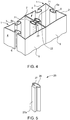
- the end plug 30 which is insertable into an end of the construction module 1.
- the end plug 30 includes a generally square end plate 31.
- a skirt 32 extends perpendicularly to the end plate 31, and is shaped so as to correspond to the internal form and dimensions of the construction module 1.
- the walls of the skirt 32 are, however, not concave but are straight, so that insertion of the end plug 30 into the construction module 1 will cause the concave sidewalls 2, 3 and 4 of the construction module 1 to flex so as to conform to the straight sides of the skirt 32. This flexing will increase the pressure between the sidewalls 2, 3 and 4 and the skirt 32, providing a tight frictional fit for the end plug 30 within the construction module 1.
- the skirt 32 is formed with internal elliptical formations 33 which are shaped and dimensioned so as to fit closely round the ends of the elliptical walls of the cavities 6a of the construction module 1.
- the external surface of the skirt 32 may be formed with ribs, or otherwise textured, to improve the frictional fit of the end plug 30 into the construction module 1.
- Figure 3B shows the external surface of the end plate 31.
- a depression 34 is formed in the end plate 31 to accommodate an air valve 35, which may be a valve similar to that found in vehicle tyres.
- the valve 35 is in communication with the underside of the end plate 31 by means of an opening 36 formed in the base of the depression 34.
- the air valve 35 is placed in the depression 34 so that it does not protrude above the external surface of the end plate 31.
- the attachment button 37 has a stem 38 and a head 39.
- the stem 38 of the attachment button 37 is dimensioned so as to be receivable in the slot 6 of the sidewalls 2, 3 and 4 of a construction module 1.
- the stem 38 is preferably circular in cross-section, but may be of square cross-section with the faces of the stem 38 aligned parallel to the sides of the square end plate 31.
- the button 39 is generally circular in plan, and in side view is semi-elliptical so as to be co-operable with the parts of the internal face of a cavity 6a of a construction module 1 which are adjacent to the slot 6.
- One purpose of the end plug 30 is to provide for a joint between two construction modules which are aligned perpendicularly to each other, with the end of one module contacting a side wall 2, 3 or 4 of the other.
- the end plug 30 may also serve to form an airtight seal at the end of the construction module 1, particularly if an adhesive or sealant is applied to the external faces of the skirt 32, or to the internal surfaces of the construction module 1, prior to inserting the end plug 30.
- the application of two end plugs 30 to a construction module may therefore provide an elongate sealed unit which may serve as part of a floating or floatable structure.
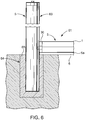
- Figure 6 shows a cross-sectional view
- Figure 7 shows a schematic perspective view, of a wall 60 and a floor 61 of a shelter.
- the wall 60 is formed from eight construction modules 1 joined side-by-side by joining elements 20.
- the planar sidewalls 5 of the construction modules 1 are arranged to form the external face of the wall 60, and optionally the exposed slots 6 at the ends of the wall 60 may be filled using filler elements 25.
- the wall 60 is erected by firstly joining the required number of construction modules 1 together as described above, then digging a foundation trench 64, inserting the lower ends of the construction modules 1 forming the wall 60 into the trench 64, and backfilling the trench with aggregate 65.
- the construction modules 1 of the wall 60 are buried to a depth of up to 1 fifth or more of the length of each construction module 1.
- a floor 61 for the shelter is formed from six construction modules 1 joined side- by-side with joining elements 20.
- Each of the construction modules 1 forming the floor is placed with its sidewall 5 uppermost, to provide a substantially continuous flat floor surface.
- Each of the construction modules 1 forming the floor 61 has an end plug 30 inserted into its end for attachment to the wall 60, the attachment button 37 of each end plug 30 engaging with the slot 6 and cavity 6a of one of the central six construction elements 1 of the wall 60, so as to fix the floor 61 and wall 60 together and leave one of the construction elements 1 of wall 60 free at each end of the wall.
- the attachment buttons 37 of the end plugs 30 of the floor 61 are inserted into the respective slots 6 and cavities 6a of the construction modules 1 of the wall before the lower ends of the construction modules 1 of the wall 60 are buried in the foundation trench 64.
- the second wall 62 is likewise constructed from seven vertically-oriented construction modules 1, joined together by joining elements 20, and with their lower ends sunk into a foundation trench 64 as described in relation to the wall 60. Since the modules 1 of the floor 61 are fixed in position relative to the wall 60 by end caps 30 fitted to the modules 1 of the floor 61, and the leftmost module of the second wall 62 (as seen in the Figure) is attached to the end module 1 of the wall 60 which extends beyond the floor 61, is not necessary to fix the modules 1 of the wall 62 to the adjacent module 1 of the floor 61.
- fixing elements may be provided having the form of two attachment buttons 37 joined end to end by their stems 38. These fixing elements may be placed at the intersections of the slots six of the vertical modules 1 forming the wall 62, and the horizontal slot 6 of the adjacent module 1 of the floor 61.
- the upper ends of the modules 1 of the wall 62 and the wall 60 are provided with end caps 30, as illustrated in Figure 8 , for the attachment of roof beams.
- Construction then moves to the phase shown in Figure 9 where a third wall 63 is added, the third wall 63 being formed by assembling eight construction modules 1 in a manner similar to wall 60.
- the ends of the modules 1 forming the floor 61 are provided with end caps 30, to attach the floor 61 to the wall 63.
- the upper ends of the modules 1 of the wall 63 are provided with end caps 30.
- the eight modules 1 of the wall 63 are arranged such that the central six modules are each attached to the end of a module of the floor 61, the furthest (as seen in the Figure) module is attached to the end module of the wall 62, and the closest (as seen in the Figure) module 1 of the wall 63 is positioned beyond the nearest edge of the floor61.
- a wall of seven modules 1 is assembled as described above, and is then placed between the end modules 1 the wall 60 and the wall 63, adjacent the edge of the floor 61.
- the lower edge of the fourth wall may be received in a foundation trench.
- the modules of the fourth wall may be fixed to the slot 6 in the edge of the floor 61, by fixing elements as described above.
- the modules 1 forming all of the four walls are substantially the same length, and are assembled so that at least their upper ends are aligned horizontally.
- roof beams 70 which in this arrangement are construction modules 1 of a length greater than the length of the modules forming the floor 61, are laid between wall 60 and wall 63, the attachment buttons 37 of the end caps 30 of the modules 1 forming the walls 60 and 63 being engaged by a slot 6 and cavity 6a of the roof beams 70.
- the roof beams 70 are preferably placed with their plain sidewall 5 uppermost, to provide a smooth surface to the exterior of the roof. This orientation of the roof beams 70 provides a slot 6 and cavity 6a on the underside of each roof beam, from which articles such as lamps, curtains or other items may be suspended.
- roof beams 70 are provided to extend between each of the modules 1 of the wall 60 and its counterpart module 1 in wall 63.
- the roof beams 70 may be joined to each other by inserting joining elements 20 into the adjacent slots 6 and cavities 6a of each adjacent pair of roof beams 70, and end plugs 30 may be inserted in the respective ends of the roof beams 70.
- the roof beams 70 may extend from the top of wall 62 to the top of the fourth wall, perpendicularly to the direction of the modules 1 of the floor 61.
- Figure 10 is a schematic illustration of how an access opening may be provided in the shelter.
- Figure 10 shows the shelter with the roof beams 70 extending between the wall 60 and the wall 63.
- the ends of the roof beams 70A and 70B can be disengaged from the wall 63.
- the corresponding modules 1A and 1B may then be slid upwardly, creating an opening D adjacent the floor 61.
- the opening D may be closed by reversing the process and moving the modules 1A and 1B downward until their upper ends are aligned with the upper ends of the adjacent modules 1 in wall 63, and then sliding the roof beams 70A and 70B to re-engage with the buttons 37 of the end caps 30 of modules 1A and 1B.
- Locking means such as conventional bolts may be provided between the modules 1 and the roof beams 70, to deny access from outside the building.
- FIG 11 shows an alternative method of constructing a shelter using the construction modules 1.
- the roof of the structure is formed by a number of roof beams 70 arranged parallel one to another.
- An end wall of the structure is formed from a plurality of modules 1 laid horizontally and joined together by means of joining elements 20 running horizontally between each adjacent pair of modules 1.
- a front wall F of the structure is formed partially by a number of horizontally-laid modules 1h, and partially by a number of vertically oriented modules 1v.
- the front wall F is formed from eight horizontally-laid modules 1h arranged one on top of another, and six vertically laid modules 1v arranged side-by-side.
- End caps (not shown) on the ends of the horizontally-laid modules 1h connect them to their adjacent vertically-laid module 1v.
- An access opening D has been created in the illustrated embodiment by sliding two of the roof beams 70A and 70B away from the front wall F, and lifting the central two of the vertical modules 1v to create the opening D.
- the cross-section of the construction module although shown as generally square in the illustrated embodiments, may be rectangular.
- the plain (i.e. non-slotted) sidewall may be one of the longer sides of the rectangle.
- the construction module may have a rhombus or diamond cross-section, and may be thinned at the comers to render them more flexible.
- Such a construction module may be flattened by bringing the obtuse-angled corners of the rhombus together, to reduce the volume of the module for shipping.
- Slots 6 and cavities 6a are formed on three sides of the construction module illustrated in the example. It will be appreciated that construction modules of square or rectangular cross-section may be provided with a slot 6 and cavity 6a on all sides or on only two opposing sides.
- one or more of the faces of the construction module 1 may include a protrusion in the form of an undercut ridge, shaped so as to be corporate wall with a slot 6 and cavity 6a of an identical module.
- the ridge is formed on a face opposite to a face of the module which has a slot 6 and cavity 6a, so that a number of identical modules may be joined side-by-side by sliding the ridge of one module into the slot of another.
- the shelter may be is constructed from fewer components as the joining elements would not be needed.
- the module may be first provided with end plugs 30 and pressurised air may be introduced through the valve 25 to inflate the module so that the faces of the module assume a substantially flat or possibly even convex shape. This will allow the slots 6 of two modules to be aligned and position side-by-side, without having to pinch the slots together.
- the joining element may then be easily introduced into the cavities 6a and the aligned and adjacent slots 6, to join the two modules together.
- air may be released from the modules 1, causing them to return to their original unstressed curvature in so far as is possible against the resistance of the joining element 20. A tight engagement between the modules 1 and the joining elements 20 may thus be provided, without excessive physical force being required to insert the joining elements 20.
- the joining elements 20 may be provided with substantially rigid locking elements 21 and an elastic or flexible bridging element 22. By using such joining elements 20, a flexible structure may be achieved. Such a flexible structure may be useful when the modules 1 are sealed by the provision of end caps 30, and the resultant buoyant modules are joined together by flexible joining elements to form a raft, pontoon or bridge or other floating structure.
- a shelter When a shelter has been formed from hollow construction modules 1, additional strength and weight may be added to the shelter by filling the constructional modules 1 with available material, such as earth, gravel, rock or the like. Modules filled with earth may have openings formed in them so that plants may be grown in the modules forming the walls of a shelter.
- available material such as earth, gravel, rock or the like.
- Modules filled with earth may have openings formed in them so that plants may be grown in the modules forming the walls of a shelter.
- the hollow nature of the modules allows them to be used also for storing water, or as pipes for transporting water.
Landscapes
- Engineering & Computer Science (AREA)
- Architecture (AREA)
- Civil Engineering (AREA)
- Structural Engineering (AREA)
- Physics & Mathematics (AREA)
- Electromagnetism (AREA)
- Chemical & Material Sciences (AREA)
- Combustion & Propulsion (AREA)
- Mechanical Engineering (AREA)
- Ocean & Marine Engineering (AREA)
- Tents Or Canopies (AREA)
Priority Applications (2)
| Application Number | Priority Date | Filing Date | Title |
|---|---|---|---|
| EP18166923.5A EP3553254A1 (de) | 2018-04-12 | 2018-04-12 | Modulare struktur |
| PCT/EP2019/059520 WO2019197655A1 (en) | 2018-04-12 | 2019-04-12 | Modular structure |
Applications Claiming Priority (1)
| Application Number | Priority Date | Filing Date | Title |
|---|---|---|---|
| EP18166923.5A EP3553254A1 (de) | 2018-04-12 | 2018-04-12 | Modulare struktur |
Publications (1)
| Publication Number | Publication Date |
|---|---|
| EP3553254A1 true EP3553254A1 (de) | 2019-10-16 |
Family
ID=61971997
Family Applications (1)
| Application Number | Title | Priority Date | Filing Date |
|---|---|---|---|
| EP18166923.5A Withdrawn EP3553254A1 (de) | 2018-04-12 | 2018-04-12 | Modulare struktur |
Country Status (2)
| Country | Link |
|---|---|
| EP (1) | EP3553254A1 (de) |
| WO (1) | WO2019197655A1 (de) |
Cited By (1)
| Publication number | Priority date | Publication date | Assignee | Title |
|---|---|---|---|---|
| CN113123466A (zh) * | 2020-01-16 | 2021-07-16 | 孖垚建筑科技(上海)有限公司 | 管材及其制造方法和管材模块及其制造方法 |
Families Citing this family (1)
| Publication number | Priority date | Publication date | Assignee | Title |
|---|---|---|---|---|
| CN110670917A (zh) * | 2019-10-31 | 2020-01-10 | 电子科技大学中山学院 | 一种模块化游泳馆及其制造方法 |
Citations (6)
| Publication number | Priority date | Publication date | Assignee | Title |
|---|---|---|---|---|
| US3370389A (en) * | 1965-03-17 | 1968-02-27 | Royalmetal Corp | Wall partitions |
| US3751865A (en) * | 1971-02-03 | 1973-08-14 | G Brigham | Modular building construction |
| CA2307524A1 (en) * | 2000-05-04 | 2001-11-04 | Wayne Bennett | Method and apparatus for forming a barrier |
| AU2010200477A1 (en) * | 2009-02-23 | 2010-09-09 | Instant Structures Pty Ltd | Wall connection arrangement and method |
| EP2264323A2 (de) * | 2009-06-17 | 2010-12-22 | Klaus Reiter | Steckverbindung |
| US9856674B1 (en) * | 2017-06-01 | 2018-01-02 | Tawny Pond | Temporary fence assembly |
-
2018
- 2018-04-12 EP EP18166923.5A patent/EP3553254A1/de not_active Withdrawn
-
2019
- 2019-04-12 WO PCT/EP2019/059520 patent/WO2019197655A1/en not_active Ceased
Patent Citations (6)
| Publication number | Priority date | Publication date | Assignee | Title |
|---|---|---|---|---|
| US3370389A (en) * | 1965-03-17 | 1968-02-27 | Royalmetal Corp | Wall partitions |
| US3751865A (en) * | 1971-02-03 | 1973-08-14 | G Brigham | Modular building construction |
| CA2307524A1 (en) * | 2000-05-04 | 2001-11-04 | Wayne Bennett | Method and apparatus for forming a barrier |
| AU2010200477A1 (en) * | 2009-02-23 | 2010-09-09 | Instant Structures Pty Ltd | Wall connection arrangement and method |
| EP2264323A2 (de) * | 2009-06-17 | 2010-12-22 | Klaus Reiter | Steckverbindung |
| US9856674B1 (en) * | 2017-06-01 | 2018-01-02 | Tawny Pond | Temporary fence assembly |
Cited By (1)
| Publication number | Priority date | Publication date | Assignee | Title |
|---|---|---|---|---|
| CN113123466A (zh) * | 2020-01-16 | 2021-07-16 | 孖垚建筑科技(上海)有限公司 | 管材及其制造方法和管材模块及其制造方法 |
Also Published As
| Publication number | Publication date |
|---|---|
| WO2019197655A1 (en) | 2019-10-17 |
Similar Documents
| Publication | Publication Date | Title |
|---|---|---|
| JP6478423B2 (ja) | パネル支持装置 | |
| US4981392A (en) | Water inflatable structural module | |
| US6219984B1 (en) | Interconnectable formwork elements | |
| US7191571B2 (en) | Modular construction blocks, building structures, kits, and methods for forming building structures | |
| US7530204B2 (en) | Climate controlled housing unit | |
| US11332921B2 (en) | Construction system for a building module | |
| KR100880853B1 (ko) | 이피에스를 이용한 부력체 및 이 부력체를 이용한 폰툰 | |
| US6367215B1 (en) | Modular construction system | |
| US4621467A (en) | Vertical-walled edge-connected panelized connectable rhombic triacontahedral buildings | |
| US20120131857A1 (en) | Inflatable Enclosure | |
| US8943760B2 (en) | Modular shelter | |
| US20070154265A1 (en) | Riparian flood wall structure | |
| KR101508123B1 (ko) | 건물옥상용 조립식 방수패널구조물 | |
| JP2004530822A (ja) | モジュール方式の海上構造体 | |
| WO2019197655A1 (en) | Modular structure | |
| US20070289228A1 (en) | Modular Structures | |
| CN110945193A (zh) | 联锁建筑砌块 | |
| US7509779B2 (en) | Lightweight building blocks | |
| JP2012011992A (ja) | アルミ構造柱による浮島造成工法 | |
| CN113802589A (zh) | 一种自锁式承台板胎膜施工方法 | |
| AU2010200477A1 (en) | Wall connection arrangement and method | |
| GB2051918A (en) | volume-enclosing Structure | |
| US6161356A (en) | Building elements | |
| CN211032941U (zh) | 混凝土浮箱 | |
| KR20100033453A (ko) | 기능성 토류판 |
Legal Events
| Date | Code | Title | Description |
|---|---|---|---|
| PUAI | Public reference made under article 153(3) epc to a published international application that has entered the european phase |
Free format text: ORIGINAL CODE: 0009012 |
|
| STAA | Information on the status of an ep patent application or granted ep patent |
Free format text: STATUS: THE APPLICATION HAS BEEN PUBLISHED |
|
| AK | Designated contracting states |
Kind code of ref document: A1 Designated state(s): AL AT BE BG CH CY CZ DE DK EE ES FI FR GB GR HR HU IE IS IT LI LT LU LV MC MK MT NL NO PL PT RO RS SE SI SK SM TR |
|
| AX | Request for extension of the european patent |
Extension state: BA ME |
|
| STAA | Information on the status of an ep patent application or granted ep patent |
Free format text: STATUS: THE APPLICATION IS DEEMED TO BE WITHDRAWN |
|
| 18D | Application deemed to be withdrawn |
Effective date: 20200603 |