EP3553258A1 - Élément de raccordement amélioré pour faisceaux de tente - Google Patents
Élément de raccordement amélioré pour faisceaux de tente Download PDFInfo
- Publication number
- EP3553258A1 EP3553258A1 EP18166929.2A EP18166929A EP3553258A1 EP 3553258 A1 EP3553258 A1 EP 3553258A1 EP 18166929 A EP18166929 A EP 18166929A EP 3553258 A1 EP3553258 A1 EP 3553258A1
- Authority
- EP
- European Patent Office
- Prior art keywords
- arm
- center
- connection element
- arms
- essence
- Prior art date
- Legal status (The legal status is an assumption and is not a legal conclusion. Google has not performed a legal analysis and makes no representation as to the accuracy of the status listed.)
- Withdrawn
Links
Images





Classifications
-
- E—FIXED CONSTRUCTIONS
- E04—BUILDING
- E04H—BUILDINGS OR LIKE STRUCTURES FOR PARTICULAR PURPOSES; SWIMMING OR SPLASH BATHS OR POOLS; MASTS; FENCING; TENTS OR CANOPIES, IN GENERAL
- E04H15/00—Tents or canopies, in general
- E04H15/32—Parts, components, construction details, accessories, interior equipment, specially adapted for tents, e.g. guy-line equipment, skirts, thresholds
- E04H15/34—Supporting means, e.g. frames
- E04H15/44—Supporting means, e.g. frames collapsible, e.g. breakdown type
- E04H15/48—Supporting means, e.g. frames collapsible, e.g. breakdown type foldable, i.e. having pivoted or hinged means
Definitions
- the invention may pertain to the technical field of tents (IPC E04H 15/00) and in particular to hinges and joints for tents (IPC E04H 15/48).
- the invention may pertain to a joint for a scissor arch.
- WO 2006/106 168 A1 discloses a large expandable arch comprising beams that are articulated with one another at the ends thereof as well as at an intermediate connection. The structure can be easily transported and installed.
- FIG. 1 discloses a cross-shaped connection element (101), hereafter called the prior art cross.
- the prior art cross comprises four arms, whereby each arm comprises a connection hole (103) for hingedly attaching a beam (102) on one of its sides.
- the prior art cross comprises limited rigidity.
- the prior art cross furthermore requires long arms for sufficient freedom of movement for hinging the attached beams. With too short arms, hinging beams can interfere unwantedly.
- the prior art cross in addition also requires long arms for enabling reaching the connection holes of the beams and/or attaching a beam onto the arm. Additionally, the prior art cross needs thick arms in order to meet the requirements for stiffness and strength as the attached beams exercise a bending moment on the cross because of their eccentricity towards the neutral axis of the arms. Also, upon folding a grid of in essence equally long beams interconnected via prior art crosses, a non-optimal compactness is reached.
- the present invention aims to resolve at least some of the problems mentioned above.
- the invention provides a structure, according to claim 1.
- connection element for a tent framework according to claim 13.
- the invention provides a method for building a tent framework, according to claim 14.
- connection element of the present invention is advantageous over the prior art cross for a plurality of reasons.
- the off-center positioning of arms allows for unhindered hinging of beams, allows to let the arms protrude less far from the connection element, and allows for easily reaching the hinging attachment of a beam and an arm. Furthermore, the off-center positioning also allows to build a grid of in essence equally long beams which can be compactly folded.
- the off-center positioning of an arm allows the hinged beams to be connected along their neutral axis thanks to two prongs. This removes unwanted bending moments due to eccentricity allowing the arms to be thin. Furthermore, because of the cavity comprising the center, the rigidity of the connection element is assured.
- the present invention concerns a structure, a connection element for a tent framework, and a method for building a tent framework.
- the invention was summarized in the corresponding section above. In what follows, the invention is described in detail, preferred embodiments are discussed, and the invention is illustrated by means of examples.
- a compartment refers to one or more than one compartment.
- the value to which the modifier "about” refers is itself also specifically disclosed.
- the invention provides a structure comprising multiple beams and a connection element.
- the connection element comprises a center and a set of elongated arms.
- Each arm comprises a length direction, a projection plane in essence perpendicular to the length direction, and an attachment means for hingedly attaching a beam.
- the projection plane thereby comprises the center.
- An arm of the set, and preferably each arm of the set, is positioned off-center at a distance from the center.
- the arm furthermore comprises a portion on each side of the projection plane of the arm via which the arm is connected to the connection element.
- the arm hence comprises two portions, one on each side of the projection plane of the arm, via each of which the arm is connected to the (remainder of the) connection element.
- an elongated arm is the elongation direction of the arm.
- an arm comprises mutually perpendicular length, height and width directions, whereby the attachment means of the arm comprises a rotation axis in essence parallel to the width direction.
- the structure is a tent framework, more preferably a scissor tent framework, and most preferably a scissor arch framework.
- connection element for a tent framework.
- the connection element comprises a center and a set of elongated arms.
- Each arm comprises a length direction, a projection plane comprising the center and in essence perpendicular to the length direction, and an attachment means for hingedly attaching a beam.
- An arm of the set, and preferably each arm of the set, is positioned off-center at a distance from the center.
- the arm furthermore comprises a portion on each side of the projection plane of the arm via which the arm is connected to the connection element.
- the invention provides a method for building a tent framework.
- the method comprises several steps. Multiple beams and a connection element are provided, whereby the connection element comprises a center and a set of elongated arms, whereby each arm of the set is positioned off-center at a distance from the center. For each of the beams, the beam is hingedly attached to an arm of the set.
- a structure according to the first aspect may comprise a connection element according to the second aspect.
- a method according to the third aspect may pertain to the assembly of the beams and the connection element of a structure according to the first aspect.
- the three aspects of the present invention are hence interrelated. Therefore, in what follows distinction between the different aspects of the invention may be left out.
- each feature described above or below, even if it has been described for a particular aspect of the invention, may pertain to each aspect of the invention.
- the present invention is advantageous for several reasons.
- the off-center positioning of arms allows for unhindered hinging of beams, allows to let the arms protrude less far from the connection element, and allows for easily reaching the hinging attachment of a beam and an arm.
- the off-center positioning also allows to build a grid of in essence equally long beams which can be compactly folded.
- the off-center positioning of an arm allows the hinged beams to be connected along their neutral axis thanks to two prongs. This removes unwanted bending moments due to eccentricity allowing the arms to be thin. Furthermore, because of the cavity comprising the center, the rigidity of the connection element is assured.
- the arm is connected via each portion of the arm to another arm of the set.
- the arm is connected via each portion to a different other arm of the set.
- the arm is connected to at least two other arms of the set.
- the portion on each side of the projection plane of the arm via which the arm is connected to the connection element is a portion on each side of the projection plane of the arm via which the arm is connected to another arm of the set.
- the arm comprises two portions, one on each side of the projection plane of the arm, via each of which the arm is connected to a different other arm of the set.
- the arms of the set form a cavity comprising the center.
- a connection element comprising a cavity comprising the center is advantageous as additional strength is provided via the two portions via which the arm is connected to the (remainder of the) connection element, while at the same time saving material and weight.
- the center is a central axis.
- the length directions of all arms of the set are thereby in essence perpendicular to the central axis.
- the rotation axes of the attachment means of all arms of the set are thereby in essence perpendicular to the central axis.
- the central axis is in essence parallel to the height direction of all arms of the set.
- a connection element may be monolithic or may comprise several interlocked arms.
- a portion is a recess via which the arm is interlocked with another arm of the set.
- the portion on each side of the projection plane of the arm via which the arm is connected to another arm of the set is a recess on each side of the projection plane of the arm via which the arm is interlocked with another arm of the set.
- Interlocking arms via recesses is advantageous as it allows to provide substantial strength against moment forces.
- the arms of the set comprise metal.
- the arm interlocked with the other arm of the set may or may not be additionally welded to the other arm of the set.
- the arm comprises a sidewall extending in the length and width directions from which each recess extends in the height direction.
- the arm comprises opposing first and second sidewalls separated in the height direction and both extending in the length and width directions, whereby a recess on a first side of the projection plane extends from the first sidewall towards the second sidewall, and whereby a recess on an opposing second side of the projection plane extends from the second sidewall towards the first sidewall.
- the set of elongated arms may comprise three, four, five, six, seven, eight, nine, ten, eleven, twelve, thirteen, fourteen, fifteen, sixteen, seventeen, eighteen, nineteen, twenty or more arms.
- the set comprises two pairs of arms, i.e. four arms, whereby the arms of a pair comprise a common projection plane in essence perpendicular to the length directions of both arms of the pair.
- the common projection planes of the two pairs are in essence perpendicular.
- each arm comprises two cuboid recesses spaced along the length direction of the arm, for mutually interlocking the arms of the set.
- the attachment means of the arms of a pair preferably the attachment means of the arms of each pair, are positioned at opposing sides of the center.
- the attachment means of an arm is a cylindrical connection hole comprising a rotation axis in essence parallel to the width direction.
- connection hole is positioned on the arm in essence centrally in the height direction. This is advantageous as a minimal amount of arm material is required for providing sufficient strength. By centrally positioning the connection hole along the height direction, over-dimensioning of arm material is avoided, which saves material and weight.
- the arm comprises a height in the height direction and a rounded surface on one longitudinal end of the arm.
- the rounded surface comprises a radius of curvature in essence equal to half of the height.
- the rotation axis of the connection hole is positioned at a distance from the one longitudinal end of the arm in essence equal to or smaller than half of the height. This is advantageous as it allows for unhindered hinging around the one longitudinal end of the arm. In addition, by rounding the longitudinal end, over-dimensioning of arm material is avoided, which saves material and weight.
- An arm may comprise a metal, an alloy, a plastic or a composite material, e.g. a fiber-reinforced material.
- an arm comprises metal, preferably aluminum or steel.
- an arm consists of metal, preferably aluminum or steel.
- an arm is monolithic.
- an arm is a monolithic metal arm, preferably a monolithic aluminum or steel arm.
- a beam comprises two prongs configured for positioning the attachment means of an arm of the connection element in between and further configured for hingedly attaching the beam to the attachment means.
- This configuration provides enlarged strength and stiffness over a single-sided attachment of a beam to an arm, cfr. Figure 1 (prior art).
- each of the prongs of a beam comprises a connection hole, whereby the connection holes of the two prongs comprise a common rotation axis for inserting an elongated member trough the connection holes of the two prongs and through the connection hole of the arm.
- the connection holes of the two prongs of the beam are cylindrical.
- each of the prongs comprises a rounded surface.
- a beam may comprise a metal, an alloy, a plastic or a composite material, e.g. a fiber-reinforced material.
- a beam comprises metal, preferably aluminum.
- a beam may comprise a beam profile and an end portion comprising the two prongs.
- the beam profile may comprise a metal, an alloy, a plastic or a composite material, e.g. a fiber-reinforced material.
- An end portion may comprise a metal, an alloy, a plastic or a composite material, e.g. a fiber-reinforced material.
- a beam comprises a beam profile, preferably an extruded beam profile, more preferably an aluminum extruded beam profile, and an end portion comprising the two prongs.
- the end portion is thereby partially insertable in the beam profile.
- the end portion comprises metal, more preferably aluminum or steel.
- the end portion consists of metal, more preferably aluminum or steel.
- Figure 3A shows a front view along the width direction (v) of an embodiment of an elongated arm (205a) according to the present invention.
- the arm is a monolithic metal arm, preferably of aluminum.
- the arm comprises mutually perpendicular length (u), height (w) and width (v) directions.
- the arm comprises two opposing surfaces in essence parallel to the length (u) and height (w) directions and spaced in the width (v) direction, whereby the arm comprises a uniform thickness in the width direction and in between the surfaces.
- the arm furthermore comprises two opposing sidewalls in essence parallel to the length (u) and width (v) directions and spaced in the height (w) direction, whereby the arm comprises a height (H1) in between the sidewalls.
- the height is larger than the thickness.
- the arm furthermore comprises two cuboid recesses, spaced (D5 > 0) in the length direction (u) and comprising a recess height (H2) in the height direction (w) in essence equal to half of the height (H1) of the arm.
- Each recess comprises in the length (u) and width (v) directions a recess dimension (D4 > 0) in essence equal to the thickness of the arm.
- the recesses extend from the same sidewall in the height direction (w) towards the opposing sidewall.
- a first recess extends from a first sidewall towards an opposing second sidewall, and another second recess extends from the second sidewall towards the first sidewall.
- the arm furthermore comprises a cylindrical connection hole (203) comprising a rotation axis in essence parallel to the width direction (v).
- the rotation axis of the connection hole is positioned centrally along the height direction (w).
- the rotation axis of the connection hole is located at a distance (D2) from the one longitudinal end of the arm of at least 8 mm.
- partial length D6 may be larger than zero or equal to zero. Preferably, D6 is larger than zero.
- Figure 3B shows a front view along the width direction (v) of an embodiment of an elongated arm (205b) according to the present invention.
- the features as disclosed in example 1 are also present in this embodiment of the arm.
- H3 is less than half of the height of the arm (H3 ⁇ 0.5 H1).
- Example 3 Dimensional aspects of an elongated arm
- table 1 comprises example dimensions of an elongated arm.
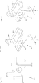
- Figure 2A shows a perspective view of an embodiment of a connection element according to the present invention.
- Figure 4 shows a top view along the common height direction of the arms of the connection element, and figure 5 shows a side view of the connection element perpendicular to the height direction.
- the connection element (201) comprises a set of two pairs of arms (205) according to any one of the previous examples 1, 2 and 3.
- the arms of each pair are in essence parallel, i.e. the length directions of the arms of each pair are in essence parallel, the height directions of the arms of each pair are in essence parallel, and the width directions of the arms of each pair are in essence parallel.
- the arms of each pair comprise a common projection plane (206) in essence perpendicular to the length directions (u) of the arms of the pair.
- the common projection planes of the two pairs are in essence perpendicular.
- the connection element comprises a central axis (207), which is in essence parallel to the height directions (w) of all four arms of the set.
- the common projection planes intersect in the central axis.
- Each arm of the set is positioned off-center, i.e. at a distance from the central axis, thereby forming a cavity (291) in between the arms which comprises the center. This distance is preferably half of the distance in between the two cuboid recesses of an arm (0.5 D5).
- Each arm comprises a recess on each side of the projection plane of the arm via which the arm is interlocked with another arm of the set.
- connection element (201) comprises in essence two-fold or in essence four-fold rotational symmetry around the central axis.
- the arms of a pair are spaced over a distance of at least 5 mm, preferably at least 10 mm, more preferably at least 15 mm, and most preferably at least 20 mm.
- connection element according to Example 4 and as shown in Figures 2A , 4 and 5 may comprise in addition to the example dimensions listed in Table 1, the additional example dimensions as enclosed in Table 2.
- Table 2 Additional example dimensions of a connection element Parameter Value (mm) D3 28.00 D7 14.00 D1 + D2 28.00 L1 67.00 L2 90.00
- Figure 2B shows a perspective view of an embodiment of a connection element according to the present invention.
- the features as disclosed in example 4 are also present in this embodiment of the arm.
- partial length D6 is in this case zero. This has the advantage of reducing material and weight and avoiding a corresponding protrusion.
- the interlocking arms are then preferably additionally welded to obtain sufficient strength.
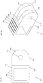
- Figures 6A and 6B show a side view and a perspective view, respectively, of an embodiment of a beam end portion (211) according to the present invention.
- Figure 7 shows a perspective view of an embodiment of a beam profile (210) according to the present invention.
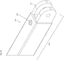
- Figure 8A shows a perspective view of a part of a beam (600) according to the present invention.
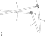
- Figures 8B and 8C show a perspective view of a portion of an embodiment of a structure according to the present invention comprising beams (600) and one or more connection elements (201).
- the structure comprises a connection element (201) and a beam (600).
- the beam (600) comprises an aluminum extruded beam profile (210) comprising two attachment holes (224).
- the beam further comprises an end portion (211) comprising two prongs (230), each comprising a cylindrical connection hole (212) and a rounded surface (299).
- the connection holes comprise a common rotation axis.
- the end portion further comprises protruding rims (223) for placement against the beam profile (210) upon insertion of the end portion in the beam profile (210).
- the end portion also comprises a set of barbs (298) for contact with one or more inner surfaces of the beam profile (210).
- a rivet (296) may be inserted for attachment of the end portion (211) to the beam profile (210).
- An arm of the connection element (201) comprises a connection hole (203).
- the arm may or may not be provided with a bearing in the connection hole.
- the arm may or may not comprise a rim on one or both sides of the connection hole.
- the connection hole (203) of the arm may be placed in between the connection holes (212) of the two prongs, and an elongate member (243) may be inserted through all three connection holes (i.e. of the two prongs and the arm) for hingedly attaching the beam (600) to the connection element (201).
- Figures 9A, 9B and 9C show, respectively, a perspective view, front view and top view of an embodiment of a scissor arch in deployed state according to the present invention.
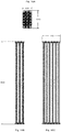
- Figures 10A, 10B and 10C show, respectively, a top view, a side view and a front view of the embodiment of the scissor arch shown in Figures 9A, 9B and 9C in compacted transport state. Due to the particular design of the connection element, the scissor arch may be folded to a compacted transport state in which the beams are adjacent.
- the scissor arch framework comprises in an embodiment a height (H9) of 3404 mm, a depth (W9) of 4150 mm and a span (L9) of 7019 mm.
- This scissor arch may be folded to a compacted cuboid transport state comprising the dimensions of 2065 mm (H20) x 448 mm (D20) x 232 mm (D21), whereby the largest dimension (H20) is in essence determined by the beams.
- a telescoping beam may comprise a central beam profile wherein two extension profiles are telescopically inserted on opposing ends.
- the extension profiles may be telescopically mounted on the outside of the central beam profile. Relative fixation may be ensured, via elongate fixation members such as, for example, pins, bolts, screws, and the like.
- Figures 11A, 11B and 11C show a top view and two perspective views, respectively, of embodiments of monolithic connection elements (201", 201"', 201"") according to the present invention.
- the connection element comprises a central axis and two pairs of in essence parallel elongated arms (205", 205"', 205"").
- Each arm comprises a length direction (u), a width direction (v) and a height direction (w) which are mutually orthogonal.
- the height direction of each arm is in essence parallel to the central axis.
- Each arm further comprises a projection plane comprising the central axis and in essence perpendicular to the length direction.
- Each arm of the set is positioned off-center at a distance from the central axis and comprises a portion on each side of the projection plane of the arm via which the arm is connected to the connection element.
- Each arm further comprises an attachment means (203"', 203"") for hingedly attaching a beam.
- connection element furthermore comprises a cavity (291", 291"', 291"") which comprises the central axis.
- the cavity is cylindrical, whereby the cylindrical cavity comprises said central axis.
- the connection element comprises four-fold rotation symmetry around the central axis.
- the attachment means is a cylindrical connection hole (203"") comprising a rotation axis in essence parallel to the width direction (v).
- the rotation axis of the connection hole is positioned centrally along the height direction (w).
- the arm ( Figure 11c ) furthermore comprises a height in the height direction and on one longitudinal end a rounded surface in essence parallel to the width direction (v) and comprising a radius of curvature in essence equal to half of the height of the arm.
- the rotation axis of the connection hole is located at a distance from the one longitudinal end of the arm which is equal to or smaller than half of the height of the arm.
- the rotation axis of the connection hole is located at a distance from the one longitudinal end of the arm of at least 8 mm.
Landscapes
- Engineering & Computer Science (AREA)
- Architecture (AREA)
- Civil Engineering (AREA)
- Structural Engineering (AREA)
- Tents Or Canopies (AREA)
Priority Applications (1)
| Application Number | Priority Date | Filing Date | Title |
|---|---|---|---|
| EP18166929.2A EP3553258A1 (fr) | 2018-04-12 | 2018-04-12 | Élément de raccordement amélioré pour faisceaux de tente |
Applications Claiming Priority (1)
| Application Number | Priority Date | Filing Date | Title |
|---|---|---|---|
| EP18166929.2A EP3553258A1 (fr) | 2018-04-12 | 2018-04-12 | Élément de raccordement amélioré pour faisceaux de tente |
Publications (1)
| Publication Number | Publication Date |
|---|---|
| EP3553258A1 true EP3553258A1 (fr) | 2019-10-16 |
Family
ID=61971998
Family Applications (1)
| Application Number | Title | Priority Date | Filing Date |
|---|---|---|---|
| EP18166929.2A Withdrawn EP3553258A1 (fr) | 2018-04-12 | 2018-04-12 | Élément de raccordement amélioré pour faisceaux de tente |
Country Status (1)
| Country | Link |
|---|---|
| EP (1) | EP3553258A1 (fr) |
Cited By (1)
| Publication number | Priority date | Publication date | Assignee | Title |
|---|---|---|---|---|
| BE1030881A1 (nl) | 2022-09-15 | 2024-04-09 | Konligo | Knooppunt voor een tentstructuur, tentstructuur, en werkwijze voor het installeren van een tentstructuur |
Citations (6)
| Publication number | Priority date | Publication date | Assignee | Title |
|---|---|---|---|---|
| US2928404A (en) * | 1958-08-13 | 1960-03-15 | Columbus Auto Parts | Collapsible shelter |
| US20030172966A1 (en) * | 2002-01-25 | 2003-09-18 | Dotterweich Martin J. | Collapsible canopy support |
| WO2006106168A1 (fr) | 2005-04-07 | 2006-10-12 | Universidad De Sevilla | Arche deployable de grandes dimensions |
| US20070240748A1 (en) * | 2006-04-18 | 2007-10-18 | Sang-Jin Bae | Canopy |
| US9163425B1 (en) * | 2011-05-17 | 2015-10-20 | Evolved Ingenuity, Llc | Hub assembly for collapsible structures |
| US20170241159A1 (en) * | 2016-02-21 | 2017-08-24 | Aaron Lyon | Collapsible Outdoor Structure |
-
2018
- 2018-04-12 EP EP18166929.2A patent/EP3553258A1/fr not_active Withdrawn
Patent Citations (6)
| Publication number | Priority date | Publication date | Assignee | Title |
|---|---|---|---|---|
| US2928404A (en) * | 1958-08-13 | 1960-03-15 | Columbus Auto Parts | Collapsible shelter |
| US20030172966A1 (en) * | 2002-01-25 | 2003-09-18 | Dotterweich Martin J. | Collapsible canopy support |
| WO2006106168A1 (fr) | 2005-04-07 | 2006-10-12 | Universidad De Sevilla | Arche deployable de grandes dimensions |
| US20070240748A1 (en) * | 2006-04-18 | 2007-10-18 | Sang-Jin Bae | Canopy |
| US9163425B1 (en) * | 2011-05-17 | 2015-10-20 | Evolved Ingenuity, Llc | Hub assembly for collapsible structures |
| US20170241159A1 (en) * | 2016-02-21 | 2017-08-24 | Aaron Lyon | Collapsible Outdoor Structure |
Non-Patent Citations (2)
| Title |
|---|
| AUTOMATION IN CONSTRUCTION, vol. 43, 2014, pages 123 - 131 |
| L. A. MIRA; A. P. THRALL; N. DE TEMMERMAN: "Deployable scissor arch for transitional shelters", AUTOMATION IN CONSTRUCTION, vol. 43, 2014, pages 123 - 131 |
Cited By (1)
| Publication number | Priority date | Publication date | Assignee | Title |
|---|---|---|---|---|
| BE1030881A1 (nl) | 2022-09-15 | 2024-04-09 | Konligo | Knooppunt voor een tentstructuur, tentstructuur, en werkwijze voor het installeren van een tentstructuur |
Similar Documents
| Publication | Publication Date | Title |
|---|---|---|
| JP3301018B2 (ja) | 構造部材 | |
| US20060053732A1 (en) | Cold-formed steel joists | |
| WO2002020917A2 (fr) | Ensemble charniere pour treillis | |
| JP4370094B2 (ja) | 棚材料 | |
| EP3553258A1 (fr) | Élément de raccordement amélioré pour faisceaux de tente | |
| WO2012099531A1 (fr) | Structure modulaire mobile multifonctionnelle | |
| CZ46595A3 (en) | Framed structure with hollow parts process of its preparation and use | |
| US4646505A (en) | Structural element | |
| US20110011027A1 (en) | Construction elements and method of using and making same | |
| WO2010104397A1 (fr) | Poutre en treillis et procédé de fabrication | |
| JP3243713B2 (ja) | スチ−ルハウスのフレ−ム部材結合体 | |
| CA2455312C (fr) | Plate-forme sans soudure | |
| EP3862502B1 (fr) | Structure de treillis modulaire | |
| CN214014751U (zh) | 一种高强结构具有稳定性能的九折型材 | |
| JP3885335B2 (ja) | 連結金具を備えた作業足場用支柱 | |
| JP2002106111A (ja) | トラス構造体 | |
| CN103243816A (zh) | 能开门洞口的钢桁架支撑及含此支撑的钢桁架筒体结构 | |
| EP0864529A2 (fr) | Elément de construction | |
| US3868760A (en) | Method of orthogonally connecting long structural members of circular and rectangular cross-section | |
| RU2633851C1 (ru) | Строительный элемент для изготовления решетчатых конструкций | |
| CN114679857A (zh) | 一种高强结构具有稳定性能的九折型材 | |
| JP2003340526A (ja) | 湾曲複合材の製造方法 | |
| EP0311849A1 (fr) | Structure en treillis pour une carrosserie de véhicule à moteur | |
| JP2006509124A (ja) | モジュラー建築ユニットおよび組み立て方法 | |
| JP6469902B1 (ja) | ネットフェンス及びその製造方法 |
Legal Events
| Date | Code | Title | Description |
|---|---|---|---|
| PUAI | Public reference made under article 153(3) epc to a published international application that has entered the european phase |
Free format text: ORIGINAL CODE: 0009012 |
|
| STAA | Information on the status of an ep patent application or granted ep patent |
Free format text: STATUS: THE APPLICATION HAS BEEN PUBLISHED |
|
| AK | Designated contracting states |
Kind code of ref document: A1 Designated state(s): AL AT BE BG CH CY CZ DE DK EE ES FI FR GB GR HR HU IE IS IT LI LT LU LV MC MK MT NL NO PL PT RO RS SE SI SK SM TR |
|
| AX | Request for extension of the european patent |
Extension state: BA ME |
|
| STAA | Information on the status of an ep patent application or granted ep patent |
Free format text: STATUS: THE APPLICATION IS DEEMED TO BE WITHDRAWN |
|
| 18D | Application deemed to be withdrawn |
Effective date: 20200603 |