EP3553335B1 - Système d'alimentation en fluides - Google Patents
Système d'alimentation en fluides Download PDFInfo
- Publication number
- EP3553335B1 EP3553335B1 EP19000161.0A EP19000161A EP3553335B1 EP 3553335 B1 EP3553335 B1 EP 3553335B1 EP 19000161 A EP19000161 A EP 19000161A EP 3553335 B1 EP3553335 B1 EP 3553335B1
- Authority
- EP
- European Patent Office
- Prior art keywords
- medium
- valve
- hollow profile
- supply system
- profile
- Prior art date
- Legal status (The legal status is an assumption and is not a legal conclusion. Google has not performed a legal analysis and makes no representation as to the accuracy of the status listed.)
- Active
Links
Images


Classifications
-
- F—MECHANICAL ENGINEERING; LIGHTING; HEATING; WEAPONS; BLASTING
- F16—ENGINEERING ELEMENTS AND UNITS; GENERAL MEASURES FOR PRODUCING AND MAINTAINING EFFECTIVE FUNCTIONING OF MACHINES OR INSTALLATIONS; THERMAL INSULATION IN GENERAL
- F16C—SHAFTS; FLEXIBLE SHAFTS; ELEMENTS OR CRANKSHAFT MECHANISMS; ROTARY BODIES OTHER THAN GEARING ELEMENTS; BEARINGS
- F16C29/00—Bearings for parts moving only linearly
- F16C29/004—Fixing of a carriage or rail, e.g. rigid mounting to a support structure or a movable part
-
- F—MECHANICAL ENGINEERING; LIGHTING; HEATING; WEAPONS; BLASTING
- F16—ENGINEERING ELEMENTS AND UNITS; GENERAL MEASURES FOR PRODUCING AND MAINTAINING EFFECTIVE FUNCTIONING OF MACHINES OR INSTALLATIONS; THERMAL INSULATION IN GENERAL
- F16C—SHAFTS; FLEXIBLE SHAFTS; ELEMENTS OR CRANKSHAFT MECHANISMS; ROTARY BODIES OTHER THAN GEARING ELEMENTS; BEARINGS
- F16C29/00—Bearings for parts moving only linearly
- F16C29/005—Guide rails or tracks for a linear bearing, i.e. adapted for movement of a carriage or bearing body there along
-
- F—MECHANICAL ENGINEERING; LIGHTING; HEATING; WEAPONS; BLASTING
- F16—ENGINEERING ELEMENTS AND UNITS; GENERAL MEASURES FOR PRODUCING AND MAINTAINING EFFECTIVE FUNCTIONING OF MACHINES OR INSTALLATIONS; THERMAL INSULATION IN GENERAL
- F16C—SHAFTS; FLEXIBLE SHAFTS; ELEMENTS OR CRANKSHAFT MECHANISMS; ROTARY BODIES OTHER THAN GEARING ELEMENTS; BEARINGS
- F16C29/00—Bearings for parts moving only linearly
- F16C29/02—Sliding-contact bearings
- F16C29/025—Hydrostatic or aerostatic
-
- F—MECHANICAL ENGINEERING; LIGHTING; HEATING; WEAPONS; BLASTING
- F16—ENGINEERING ELEMENTS AND UNITS; GENERAL MEASURES FOR PRODUCING AND MAINTAINING EFFECTIVE FUNCTIONING OF MACHINES OR INSTALLATIONS; THERMAL INSULATION IN GENERAL
- F16C—SHAFTS; FLEXIBLE SHAFTS; ELEMENTS OR CRANKSHAFT MECHANISMS; ROTARY BODIES OTHER THAN GEARING ELEMENTS; BEARINGS
- F16C29/00—Bearings for parts moving only linearly
- F16C29/08—Arrangements for covering or protecting the ways
- F16C29/082—Arrangements for covering or protecting the ways fixed to the way
-
- F—MECHANICAL ENGINEERING; LIGHTING; HEATING; WEAPONS; BLASTING
- F16—ENGINEERING ELEMENTS AND UNITS; GENERAL MEASURES FOR PRODUCING AND MAINTAINING EFFECTIVE FUNCTIONING OF MACHINES OR INSTALLATIONS; THERMAL INSULATION IN GENERAL
- F16C—SHAFTS; FLEXIBLE SHAFTS; ELEMENTS OR CRANKSHAFT MECHANISMS; ROTARY BODIES OTHER THAN GEARING ELEMENTS; BEARINGS
- F16C29/00—Bearings for parts moving only linearly
- F16C29/08—Arrangements for covering or protecting the ways
- F16C29/084—Arrangements for covering or protecting the ways fixed to the carriage or bearing body movable along the guide rail or track
-
- F—MECHANICAL ENGINEERING; LIGHTING; HEATING; WEAPONS; BLASTING
- F16—ENGINEERING ELEMENTS AND UNITS; GENERAL MEASURES FOR PRODUCING AND MAINTAINING EFFECTIVE FUNCTIONING OF MACHINES OR INSTALLATIONS; THERMAL INSULATION IN GENERAL
- F16C—SHAFTS; FLEXIBLE SHAFTS; ELEMENTS OR CRANKSHAFT MECHANISMS; ROTARY BODIES OTHER THAN GEARING ELEMENTS; BEARINGS
- F16C2326/00—Articles relating to transporting
- F16C2326/58—Conveyor systems, e.g. rollers or bearings therefor
-
- F—MECHANICAL ENGINEERING; LIGHTING; HEATING; WEAPONS; BLASTING
- F16—ENGINEERING ELEMENTS AND UNITS; GENERAL MEASURES FOR PRODUCING AND MAINTAINING EFFECTIVE FUNCTIONING OF MACHINES OR INSTALLATIONS; THERMAL INSULATION IN GENERAL
- F16C—SHAFTS; FLEXIBLE SHAFTS; ELEMENTS OR CRANKSHAFT MECHANISMS; ROTARY BODIES OTHER THAN GEARING ELEMENTS; BEARINGS
- F16C29/00—Bearings for parts moving only linearly
- F16C29/04—Ball or roller bearings
- F16C29/06—Ball or roller bearings in which the rolling bodies circulate partly without carrying load
- F16C29/068—Ball or roller bearings in which the rolling bodies circulate partly without carrying load with the bearing body fully encircling the guide rail or track
Definitions
- the invention relates to a medium supply system with at least one stationary mounted hollow profile carrying a gaseous or liquid medium and a rail-guided transport carriage equipped with a medium collector.
- the air supply is an elongated tube that has a longitudinal slit.
- the longitudinal slit is closed from the inside of the pipe with a valve membrane covering the longitudinal slit.
- a cam rests on the valve membrane inside the air tap, which lifts the valve membrane from the longitudinal slot so that compressed air passes out of the tube into the air tap.
- the EP 1 816 361 A1 describes two air-bearing compound slides of an apparatus for the production of patterns lithographically produced by means of an electron beam.
- Each slide of the individual compound slide has the shape of a square tube as a fixed bearing, which encloses a square-shaped guide rail.
- the square tube slide is supported against the guide rail by several air bearings.
- a large number of differential pressure-controlled pilot valves are located along the hollow, compressed air-carrying guide rail. The square tube carriage sliding along the guide rail draws the compressed air for its air bearings when passing over the pilot valves.
- the linear unit consists of a cylinder or a linear drive such as a motor and ball screw rod or threaded rod with nut element, an air rail arranged parallel to this, which runs along its entire length Contains tapping points that are arranged at short intervals and a compressed air collector that can be moved on suitable guide rails of the air rail.
- the present invention is based on the problem of creating a medium supply system for one or more rail-guided transport carriages for workpieces, with which the transport carriages can be supplied with a gaseous or liquid medium safely and without leakage over at least part of their route.
- a medium supply system is created with which, for example, rail-guided transport vehicles can be supplied with a gaseous or liquid medium without the individual transport vehicle having to pull a supply hose behind it.
- the transport wagon along the transport route, the transport wagon, at least in some areas, a hollow profile guiding the medium is arranged, along which the medium collector is guided.
- many valves are usually arranged one behind the other with smaller or larger distances in the hollow profile.
- the valves which are generally closed outside the medium consumer, form a transfer track.
- the distance between the valves arranged in the hollow profile and the length of the medium collector are designed in such a way that, adapted to the speed of the transport carriage driving over them, the valves have enough time to open, a sufficient medium volume - e.g. to maintain the printer - to hand over and close again.
- the transport trolley or the medium collector can also be equipped with a medium reservoir.
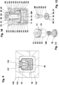
- the figure 2 shows a longitudinal section through the hollow profile (10) and the medium collector (130) of a medium supply system that enables a vacuum connection to a transport vehicle.
- the hollow profile (10) here is a continuous cast profile made from an aluminum alloy in the form of a square tube (11) which has an essentially square cross section. For example, with a cross-sectional edge length of 30 mm, it has a wall thickness that corresponds to a tenth to a quarter of this cross-sectional edge length.
- the longitudinal edges (12) of the square tube (11), cf. figure 1 are rounded with a radius of eg 4 mm.
- Two O-ring grooves (112) arranged next to one another are worked into the inner wall of the cap recess (111) between the threaded bore (116) and the base. O-rings (113) or comparable sealants are inserted in the O-ring grooves (112).
- the bridging cap (120) consists of a truncated pyramid area (121) and a seating area (122).
- the seating area (122) protrudes, for example, 20 mm into the interior (19) of the square tube (11), while the truncated pyramid area (121) represents a tapering extension of the square tube (11).
- the truncated pyramid area (121) has a base contour that corresponds to the outer circumferential edge of the square tube (11). With a pyramid apex angle of ten degrees, for example, it is 34.4 mm long. It tapers - starting from the foot contour - towards the free end of the transfer cap (120). A threaded hole is arranged in the face of the free end as a medium connection (125).
- the transfer cap (120) creates a hollow profile closure onto which the medium collectors (130) can drive. With the aid of the ramp-like outer contour of the transfer cap (120), the seals of the medium collector (130) are widened when driving on—without additional wear and too much effort, cf. Figures 13 to 15 .
- valve installation bores (13) are arranged one behind the other at equidistant intervals in a side wall of the square tube (11).
- all valve installation bores (13) have center lines that lie in one plane.
- the center line of the square tube (11) is also located in this plane.
- Suction valves (20) sit in the valve installation bores (13), their free end faces or end faces lie in the outer wall plane of the square tube (11), in which the valve installation bores (13) are incorporated.
- the hollow profile can also be a cylindrical tube, a rectangular tube or another polygonal tube.
- the hollow profile can be subdivided in the interior by one or more intermediate walls in the longitudinal direction of the hollow profile, so that media-carrying zones which are separated from one another arise.
- the individual suction valve (20) to be inserted into a valve installation bore (13) consists of a valve seat sleeve (21) and a vacuum valve member (30), cf. figure 4 .
- the essentially tubular valve seat sleeve (21) comprises a fastening area (22) and a guide area (23). With a length of 8.5 mm in the attachment area (22), for example, it has a diameter of 19 mm.
- the 3.2 mm wide attachment area (22) has a circumferential annular groove approximately in the middle, the depth of which measures 0.2 mm, for example.
- the recess of the valve seat sleeve (21) has a conical surface (27) as the inner wall in the fastening area (22), the largest diameter of which measures 17.85 mm and the apex angle of which encloses an angle of 60 degrees.
- the depth of the conical surface (27) corresponds to approximately 53% of the wall thickness of the square tube (11).
- a 0.7 mm deep cylinder countersink connects to the conical surface (27).
- the flat bottom surface of the cylinder countersinks serves as a seat sealing surface (28) for an O-ring (38) seated on the vacuum valve member (30).
- the seat sealing surface (28) is adjoined by a cylindrical through-bore which ends at the lower end of the guide area (23) in a planar holding face (24).
- the guide area (23) has an outer diameter of 18.3 mm, for example.
- the transition area between the guide area (23) and the attachment area (22) has the shape of a straight truncated cone whose cone angle is 40 degrees.
- the vacuum valve member (30) is shown in its open position. It sits in the recess (26) of the valve seat sleeve (21) with a radial play of, for example, 0.14 mm.
- the maximum opening stroke measures 3.1 mm.
- the vacuum valve member (30) consists of a valve disk (31), for example four guide elements (36) and a central magnetic holding sleeve (35), cf. figure 5 .
- the magnet holding sleeve (35) together with the four guide elements (36) is formed on the valve plate (31).
- the valve disk (31) is a flat disc with a wall thickness of 1.7 mm. Its flat underside forms the link sealing surface (33). It has an outer wall in the form of a conical centering surface (32) whose cone angle includes 60 degrees.
- the valve plate (31) is followed by a 1.1 mm thick cylindrical shoulder, which has a maximum diameter of 13.3 mm, for example. In the central area, the paragraph has a circumferential groove (34) in which an O-ring (38) is inserted.
- equidistantly divided guide elements for example 10.8 mm long, which end in rear grip hooks (37) in the region of their free end.
- the guide elements (36) rest against the recess (26) of the valve seat sleeve (21) with play.
- their rear gripping hooks (37) lie flat on the holding face (24) of the valve seat sleeve (21).
- the guide elements (36) include the central magnet holder (35), which is eg 3.8 mm long.
- the latter has a central bore in which a suction valve magnet (39) which is eg 5 mm long is arranged, cf. figure 5 .
- the suction valve magnet (39) has a diameter of 5 mm, for example. It is glued into the magnet holder (35) or clamped there.
- the valve disk (31) has a wall thickness of 0.4 to 1.1 mm in the area of the suction valve magnet (39). The valve opening force increases with decreasing wall thickness of the valve disk (31).
- the figure 1 shows a medium collector (130) provisionally seated on the hollow profile (10). He is in figure 2 partly in longitudinal section and in figure 3 shown in cross section.
- the medium collector (130) essentially consists of a receiving housing (131), which consists of a housing upper part (132) and a housing lower part (133).
- The, for example, cuboid transfer case (131) forms an assembled square tube made, for example, from an aluminum alloy, which completely surrounds the hollow profile (10) over a length that corresponds to at least four to six times the width of the hollow profile.
- the height and the In the exemplary embodiment, the width of the transfer housing (131) corresponds to two to 2.5 times the width of the hollow profile.
- the regular inner wall (134) of the transfer housing (131) is on average spaced, for example, everywhere 7.5 mm from the outer wall of the hollow profile (10).
- the receiving housing (131) is closed at the front and rear with a front cover (140), cf. figures 2 and 8th .
- the front cover (140) sits between the inner wall (134) of the transfer housing (131) and the hollow profile (10).
- the individual end cap (140) has an end cap flange (141) with which it is fastened, for example with four screws each, to the respective end face of the medium collector (130).
- the front cover (140) has an O-ring groove (142), in which a sealing ring is inserted, in the outer area with which it sits in the inner wall (134).
- In its central cover recess (146) it has two inner, circumferential sealing ring grooves (143) parallel to one another, in each of which a lip seal (144)—with, for example, two sealing lips oriented away from one another—is inserted.
- the four lip seals (144) of the two front covers (140) center the medium collector (130) relative to the hollow profile (10), but without supporting the weight of the medium collector (130) on the hollow profile (10).
- the weight of the medium collector (130) is absorbed by the transport carriage (2) supporting the medium collector (130), cf. figure 8 .
- the transport carriage (2) which is usually mounted on its own guide rail, has, for example, a guide frame (3) which mounts the transfer housing (131). Transverse to the direction of travel (9), the transfer housing (131) is supported on the guide frame (3) via a number of centering springs (5). At least one centering spring (5) in the form of a helical compression spring is arranged in each of the normal directions of the four side walls of the hollow profile (10). In the direction of travel (9), the end faces (138) of the transfer housing (131) lie against the stop flanges (4) of the guide frame (3) with a maximum play of 0.2 mm.
- a strip-shaped permanent magnet (145) is arranged on the upper inner wall of the upper housing part (132), opposite the valves (20, 50).
- the eg 12 mm wide permanent magnet (145) is screwed to the upper part of the housing, cf. figure 1 and 7 , Has a length that corresponds to at least half the length of the takeover housing (131).
- the permanent magnet (145) sitting directly above the valves (20, 50) protrudes just as far into the transmission cavity (137) in that the valves (20, 50) do not yet touch it when the valve member (30, 80) is open.
- the air gap clearance is usually 0.1 mm.
- a mechanical valve closing ramp (147) made, for example, of plastic.
- the latter has, for example, a ramp surface (148), the wall of which corresponds in some areas to the curvature of a cylinder jacket section, the radius of which measures 24 mm, for example.
- the radius ends 2.5 mm in front of the front cover (140) in a tangent parallel to the hollow profile (10) which is 0.1 to 0.2 mm above the wall of the hollow profile (10).
- the width of the ramp surface (148) corresponds to the width of the permanent magnet (145).
- the ramp surface (148) facing the valves (20, 50) is optionally provided with a corresponding surface coating, which provides this surface with a particularly low coefficient of friction.
- the individual valve closing ramp (147) is fastened with two screws to the nearest front cover (140), cf. Figures 3 and 9 .
- the opening stroke of the vacuum valve member (30) is limited by its hooks (37) so that the vacuum valve member (30) straightens the strip-shaped permanent magnet (145). not touched yet.
- the force of attraction between the cylindrical suction valve magnet (39) of the vacuum valve member (30) and the strip-shaped permanent magnet (145) of the medium collector (130) is sufficient to - despite the suction force of the air flowing along the vacuum valve member (30) into the hollow profile (10) - to stay open.
- the valve closing ramp (147) passes over the vacuum valve member (30). Its ramp surface (148) presses the valve disk (31) mechanically in the closing direction of the suction valve (20). If the front cover (140) of the medium collector (130) travels over the suction valve (20), the vacuum valve member (30) is again in its closed position.
- the vacuum present in the interior (19) of the hollow profile (10) supports the closing stroke.
- a permanent magnet can be arranged in the medium collector (130), the polarity of which is selected in relation to the polarity of the suction valve magnet (39) of the valve disk so that the suction valve magnet (39) is repelled.
- the permanent magnet in the medium collector (130) can—like the strip-shaped permanent magnet (145)—be an electromagnet.
- valve closing ramp (147) with one or more compressed air nozzles which temporarily eject compressed air against the valve disk to close the suction valve (20), for example in a spurt manner, in order to close the suction valve (20).
- the compressed air required for this comes, for example, from a compressed air reservoir carried along in the transport vehicle (2).
- the Figures 7 to 12 show a medium supply system that works with a compressed gas, such as compressed air.
- the figure 7 shows as a medium guide profile suitable for compressed air hollow profile (10) on which the already from the figures 2 and 3 known medium buyer (130) is postponed.
- a large number of pressure valves (50) are arranged in the hollow pressure profile (40), for example on only one side wall.
- a single pressure valve (50) is in figure 10 shown assembled.
- the pressure valve (50) consists of a two-part pressure valve housing (51), a multi-part pressure valve member (80) and a valve spring (100).
- the pressure valve housing (51), cf. figure 11 consists of a housing pot (52) and a housing screw cover (70).
- the one after the Figures 9 to 11 The upside-down housing pot (52) has a flat housing base (53) at the top, which after installation in the pressure profile (40) is flush with its outer wall.
- the largest part of the radial, cylindrical outer wall of the housing pot (52) has a diameter of 23 mm, for example. Only the upper area, for example 3.5 mm wide, which adjoins the housing base (53), has an external thread (54) with an external diameter of, for example, 24 mm.
- the housing pot (52) On its underside, the housing pot (52) has a central cylindrical inflow bore (66), e.g. 16.4 mm deep, which ends in a flat bottom.
- the diameter of the inflow hole (66) measures e.g. 18 mm.
- the lower area of this bore has an internal thread (68) in order to be able to screw in the housing screw cover (70) there.
- At least two access transverse bores (56) open into the inflow bore (66) in the vicinity of the inflow base (67) of this bore.
- a central outflow stage bore (61) incorporated from above. This opens into the inflow bore (66).
- the outflow stage bore (61) has a head portion (62) and a shank portion (63).
- the head area (62) has a diameter of 11.2 mm, for example. It is eg 10 mm deep.
- the narrow shaft area (63) adjoins the head area (62) via a flat outflow sealing surface (64). The latter only has a diameter of eg 8 mm.
- the pressure valve member (80) guided on the walls is seated in the outflow stage bore (61) and in the inflow bore (66).
- the pressure valve member (80) consists of a valve head (81), a valve stem (83) and a valve base (90).
- the valve stem (83) arranged between the valve head (81) and the valve base (90) has an external thread in the lower area, onto which the valve base (90) is screwed.
- the valve stem (83) has a central longitudinal outflow bore (86) which opens into two intersecting outflow transverse bores (82) arranged in the valve head (81).
- the individual outflow transverse bores have an oval cross-section, with the center lines of the oval lying in a plane which is oriented normal to the center line of the pressure valve (50).
- valve head (81) and the valve stem (83) there is a shaft ring groove (84) in which a head sealing ring (85) is arranged.
- the pressure valve (50) When the pressure valve (50) is closed, the latter seals the transmission cavity (137) from the interior (19) of the pressure profile (40).
- the valve foot (90) has a central foot step bore (97), which consists of a foot internal thread (98) at the top
- the valve foot (90) is attached to the foot thread (87) of the valve stem (83).
- the lower area of the foot step bore (97) is the foot inflow area (99).
- the valve base (90) has a base guide area (91) with overflow notches (92) and an air distribution area (93) in the form of a recess.
- the foot guide area (91) which is e.g. 3 mm wide, guides the pressure valve member (80) in the inflow bore (66) with a play of e.g. 0.1 mm.
- the total of the radial overflow notches (92) of the foot guide area (91) releases a cross section that corresponds at least to the cross section of the foot inflow area (99).
- a flat ring groove (96) is arranged in the lower free end face, in which a valve spring (100) arranged in the pressure valve housing (51) is guided radially.
- the air distribution area (93) above the foot guide area (91) has a height of 3.5 mm and a diameter of 13.5 mm, for example.
- the housing screw cover (70) that closes the housing pot (52) is a flanged cover with a central spring seat indentation (78).
- the outer diameter of the housing screw cover (70) is 20 mm.
- the flange has a wall thickness of 2 mm.
- the front face of the housing screw cap (70) in the valve (50) is the inflow sealing face (71) in the mounted pressure valve (50). When the pressure valve (50) is closed, the foot sealing ring (95) rests on it with a seal.
- valve spring (100) a low spring rate helical compression spring, is installed in the pressure valve housing (51) between the spring seat countersink (78) of the housing screw cover (70) and the plane ring groove (96) of the pressure valve member (80).
- the latter has a valve installation bore (13) and a blind seat hole (48) for each pressure valve (50), cf. figure 8 .
- the valve installation bore (13) has an internal thread into which the external thread (54) of the pressure valve housing (51) is screwed.
- the seat blind hole (48) is on the center line of the valve mounting hole (13). It is a recess, for example 1 mm deep, in the inner wall of the pressure profile (40), which is arranged opposite the wall carrying the valve installation bore (13).
- the blind seat hole (48) improves the seating stability of the pressure valve (50). For example, it can be used as a bonding surface.
- the figure 8 shows a just closed pressure valve (50) on the left.
- the pressure valve member (80) is fully retracted so that the free end face of the valve head (81) is in one plane with the free end face of the housing pot (52) and the valve spring (100) is compressed.
- the pressure valve interior (79) is sealed off from the environment of the pressure profile (40) by the head sealing ring (85).
- the compressed air present in the pressure valve interior (79) via the access transverse bores (56) holds the pressure valve member (80) in the closed position, since the inner end face of the valve base (90) is larger than the area of the lower end face of the valve head (81) on which the compressed air is available.
- the foot sealing ring (95) keeps the pneumatic connection between the pressure valve interior (79) and the foot inflow area (99) closed.
- valve foot (90) is loaded by the force of the valve spring (100) in order to increase the closing force to be selected only slightly smaller than the required valve opening force.
- the sum of the pneumatic closing force of the pressure valve member (80) and the pressure valve gravity is reduced by the valve spring force acting in the opposite direction to such an extent that the pressure valve (50) remains closed without the addition of the magnetic force acting in the opening direction.
- the pressure valve (50) - contrary to the exemplary embodiments shown - is installed in a lateral or lower wall of the pressure profile (40), depending on the sensitivity of the pressure valve, the change in the pressure valve gravity must be taken into account in the force balance acting on the pressure valve member.
- the closing movement of the pressure valve (50) takes place in the same way as the suction valve (20). All components of these valves (20, 50) are made of plastic in order to weaken the magnetic effect of the magnets (39, 59, 145) as little as possible.
- FIGS. 13 to 15 show a sketch of the storage and the vacuum or compressed gas supply of the medium supply system with at least three bearing points (161 - 163).
- the medium guide profile (10, 40) is secured on both sides by means of the in figure 6 shown transfer cap (120) closed.
- a supply arm (165, 166) is arranged in front of and behind the medium guide profile (10, 40) as a bearing point (161, 163).
- each supply arm (165, 166) is mounted in a supply swivel bearing (167).
- a medium connection is accommodated in each supply swivel bearing (167) in addition to a swivel device, eg a pneumatic swivel motor.
- Each pivoting device has a pivoting range of 90 degrees.
- the starting point supply arm (165) is pivoted away to the left in order to give the medium collector (130) the opportunity to drive onto the medium guide profile (10, 40) via the transfer cap (120).
- the transfer cap (120) In order to seal the medium guide profile (10, 40) from the environment when the starting point supply arm (165) is pivoted away, there is a non-return valve in each transfer cap (120), directly behind the medium connection (139). The latter, for example in the case of a pressure profile (40), closes immediately as soon as the starting point supply arm (165) pivots away from the transfer cap (120).
- the starting point supply arm (165) is pivoted clockwise again against the transfer cap (120) in order to supply the medium guide profile with compressed air again after the non-return valve has opened .
- an intermediate pivoting support (171) which supports the medium guide profile (10, 40), e.g folded out of the way. As soon as the medium remover (130) has passed the intermediate pivoting support (171), it folds back into its original position.
- the intermediate pivoting support (171) can be equipped, for example, with a pneumatic clamping device whose clamping jaws clamp around the medium guide profile (10, 40) on both sides in order to be able to additionally support forces acting in the longitudinal direction of the medium guide profile (10, 40).
- the support pivot bearing (172) is replaced by a supply pivot bearing (167).
- the end point supply arm (166) Shortly before the medium collector (130) reaches the right-hand end of the medium guide profile (10, 40), the end point supply arm (166) is pivoted out of the way in a clockwise direction by its supply pivot bearing (167) - interrupting the medium supply there, so that the medium collector (130 ) can leave the medium guide profile undisturbed. Immediately after the medium consumer has passed the bearing point (163), the end point supply arm (166) pivots back into its starting position in order to supply the medium guide profile (10, 40)—for example with compressed air again.
- the desired gas pressure is maintained in the interior of the medium-guiding profile (10, 40), although medium consumers (130) are constantly driving onto the medium-guiding profile or leaving it again.
Landscapes
- Engineering & Computer Science (AREA)
- General Engineering & Computer Science (AREA)
- Mechanical Engineering (AREA)
- Self-Closing Valves And Venting Or Aerating Valves (AREA)
- Lift Valve (AREA)
- Quick-Acting Or Multi-Walled Pipe Joints (AREA)
Claims (9)
- Système d'alimentation de fluides, pourvu d'au moins un profilé creux (10, 40) logé de manière stationnaire, conduisant un fluide (1) gazeux ou liquide et d'un chariot de transport (2) guidé sur des rails, équipé d'un receveur de fluide (130),- le receveur de fluide (130) adjacent au moins par zones au profilé creux (10, 40) étant susceptible d'être guidé le long de celui-ci,- entre le receveur de fluide (130) et le profilé creux (10, 40) étant présente une cavité de transmission (137) fermée,- le receveur de fluide (130) reprenant le fluide présent dans le profilé creux (10, 40) par l'intermédiaire de soupapes (20, 50) placées dans le profilé creux (10, 40),- dans la cavité de transmission (137) du receveur de fluide (130) débouchant l'orifice (29, 59) d'au moins une soupape (20, 50),- la soupape (20, 50) respectivement franchie par le receveur de fluide (130) étant susceptible de s'ouvrir par déclenchement magnétique et- en quittant la cavité de transmission (137), la soupape (20, 50) ouverte franchie étant susceptible de se fermer par voie mécanique, pneumatique ou magnétique,caractérisé en ce que le receveur de fluide (130) possède un boîtier de reprise entourant la section transversale du profilé creux (10, 40), recevant la cavité de transmission (137), qui sur ses faces frontales traversées par le profilé creux (10, 40) est fermé de manière coulissante en étant étanche au fluide.
- Système d'alimentation de fluides selon la revendication 1, caractérisé en ce que dans le receveur de fluide (130) est placé au moins un aimant (145) ou un groupe d'aimants destiné à ouvrir les soupapes (20, 50), le ou les aimants étant excités de manière permanente ou par voie électrique, alors que les soupapes (20, 50) contiennent une matière magnétique ou magnétisable.
- Système d'alimentation de fluides selon la revendication 1, caractérisé en ce que le profilé creux (10, 40) est un tube carré, doté d'arêtes longitudinales (12) arrondies.
- Système d'alimentation de fluides selon la revendication 1, caractérisé en ce que dans le boîtier de reprise (131) sont placés des moyens (145) provoquant la fermeture des soupapes (20, 50).
- Système d'alimentation de fluides selon la revendication 1, caractérisé en ce que le profilé creux (10) est un profilé de pression conduisant de l'air comprimé et en ce que la soupape (50) individuelle est une soupape de refoulement.
- Système d'alimentation de fluides selon la revendication 5, caractérisé en ce que la soupape de refoulement (50) comporte un élément (80) de soupape de refoulement dont la force de fermeture est limitée au moyen d'un ressort de soupape (100).
- Système d'alimentation de fluides selon la revendication 1, caractérisé en ce que le profilé creux (10) est un profilé d'aspiration conduisant un vide et en ce que la soupape (20) individuelle est une soupape d'aspiration.
- Système d'alimentation de fluides selon la revendication 1, caractérisé en ce que le profilé creux (10, 40) est logé de manière stationnaire sur au moins trois points d'appui (161 à 163), au moins deux points d'appui (161, 163) étant constitués d'un dispositif de pivotement (167) et d'un bras d'alimentation (165, 166), alors que tous les autres points d'appui (162) comportent en remplacement d'un bras d'alimentation (165, 166) un support intermédiaire (171).
- Système d'alimentation de fluides selon la revendication 8, caractérisé en ce que toujours un seul bras d'alimentation (165, 166) ou un support intermédiaire (171) ne contribuent pas à porter le profilé creux (10, 40).
Applications Claiming Priority (1)
| Application Number | Priority Date | Filing Date | Title |
|---|---|---|---|
| DE102018002950.7A DE102018002950B4 (de) | 2018-04-11 | 2018-04-11 | Mediumsversorgungssystem |
Publications (2)
| Publication Number | Publication Date |
|---|---|
| EP3553335A1 EP3553335A1 (fr) | 2019-10-16 |
| EP3553335B1 true EP3553335B1 (fr) | 2023-05-31 |
Family
ID=66091833
Family Applications (1)
| Application Number | Title | Priority Date | Filing Date |
|---|---|---|---|
| EP19000161.0A Active EP3553335B1 (fr) | 2018-04-11 | 2019-04-01 | Système d'alimentation en fluides |
Country Status (2)
| Country | Link |
|---|---|
| EP (1) | EP3553335B1 (fr) |
| DE (1) | DE102018002950B4 (fr) |
Families Citing this family (2)
| Publication number | Priority date | Publication date | Assignee | Title |
|---|---|---|---|---|
| CN113021015A (zh) * | 2019-12-25 | 2021-06-25 | 苏州市阳山机械有限公司 | 镶钢导轨的安装定位结构及方法 |
| CN114562586B (zh) * | 2022-02-28 | 2024-01-26 | 北京半导体专用设备研究所(中国电子科技集团公司第四十五研究所) | 一种气体切换用集控模块 |
Citations (1)
| Publication number | Priority date | Publication date | Assignee | Title |
|---|---|---|---|---|
| DE7914156U1 (de) * | 1979-09-06 | Mueller, Hermann, Dipl.-Ing., 7460 Balingen | Lineareinheit mit beweglichen Druckluftabnehmern, wobei die Druckluftübertragung ohne mitzuführende Leitungen erfolgt |
Family Cites Families (8)
| Publication number | Priority date | Publication date | Assignee | Title |
|---|---|---|---|---|
| FR2119907B3 (fr) | 1970-12-31 | 1973-11-30 | Heckert Fritz K Marx | |
| JPS6145110A (ja) * | 1984-08-06 | 1986-03-05 | Nippon Seiko Kk | スライダ−装置 |
| DE19917143A1 (de) * | 1999-04-16 | 2000-10-26 | Dlr Ev | Luftkissentransportsystem |
| EP1215145A1 (fr) * | 2000-12-11 | 2002-06-19 | Abb Research Ltd. | Dispositif de transport avec coussin d'air et procédé de fonctionnement d'un tel dispositif de transport |
| WO2006043434A1 (fr) | 2004-10-18 | 2006-04-27 | Nikon Corporation | Dispositif de soutien et dispositif d'etape, dispositif d'exposition |
| US20060124864A1 (en) | 2004-12-14 | 2006-06-15 | Nikon Corporation | Air bearing compatible with operation in a vacuum |
| US7567339B2 (en) | 2006-09-08 | 2009-07-28 | Asml Netherlands B.V. | Lithographic apparatus with gas bearing supply mechanism and device manufacturing method |
| DE202015006927U1 (de) * | 2015-10-06 | 2015-10-26 | Günther Zimmer | Reibgehemme mit Wege- und Sperrventilen |
-
2018
- 2018-04-11 DE DE102018002950.7A patent/DE102018002950B4/de not_active Expired - Fee Related
-
2019
- 2019-04-01 EP EP19000161.0A patent/EP3553335B1/fr active Active
Patent Citations (1)
| Publication number | Priority date | Publication date | Assignee | Title |
|---|---|---|---|---|
| DE7914156U1 (de) * | 1979-09-06 | Mueller, Hermann, Dipl.-Ing., 7460 Balingen | Lineareinheit mit beweglichen Druckluftabnehmern, wobei die Druckluftübertragung ohne mitzuführende Leitungen erfolgt |
Also Published As
| Publication number | Publication date |
|---|---|
| DE102018002950A1 (de) | 2019-10-17 |
| EP3553335A1 (fr) | 2019-10-16 |
| DE102018002950B4 (de) | 2023-07-06 |
Similar Documents
| Publication | Publication Date | Title |
|---|---|---|
| DE69314294T3 (de) | Gleitstellglied | |
| DE3810989A1 (de) | Vorrichtung zur handhabung und insbesondere zum transport von gegenstaenden | |
| DE1301878B (de) | Wahlweise zum Druckgasausstoss oder zum Gasansaugen dienende Vorrichtung, insbesondere zur Verwendung bei der Glasverformung | |
| DE3618827C2 (fr) | ||
| DE102010056367A1 (de) | Linearstellglied | |
| DE2703349A1 (de) | Steuerventilvorrichtung fuer einen aufzug zum einstellen auf ein aufwaertsbefindliches niveau | |
| DE102010047365A1 (de) | Vorrichtung zum Fördern von Flüssigkeiten | |
| DE2755239C2 (de) | Pneumatischer Antrieb für Schalt- und Stellglieder | |
| EP3553335B1 (fr) | Système d'alimentation en fluides | |
| DE4436045A1 (de) | Ausgleichselement | |
| DE8224788U1 (de) | Industrie-roboter | |
| DE3019119C2 (de) | Pneumatischer Antrieb für Schalt- und Stellglieder | |
| DE1580886A1 (de) | Gaskissenfahrzeug | |
| DE102011056101A1 (de) | Verdrehsichere Anschlagvorrichtung für transportierte Gegenstände | |
| DE7502826U (fr) | ||
| DE102010056035A1 (de) | Anschlagmodul zum positionsgenauen Anhalten eines Werkstücks | |
| DE4040148A1 (de) | Ventil | |
| DE3222557C2 (de) | Vereinzelungsvorrichtung für Schrauber, Nietmaschinen, Einsetzmaschinen od. dgl. | |
| DE1143108B (de) | Hydraulik-Stossdaempfer fuer Steuerregler von Fluessigkeitsverteilern zum Aufrechterhalten der Hoehenlage eines Fahrzeugaufbaues oder -rahmens | |
| DE202004019495U1 (de) | Durch Druckmitteldruck, insbesondere pneuamtisch, betätigte Kolben-Zylinder-Einheit, bei welcher ein mit einer Kolbenstange verbundener Kolben durch Druckmittelbeaufschlagung linear bewegbar ist, z.B. druckmittelbetätigbare Kniehebelspannvorrichtung, insbesondere für den Karosseriebau der Kfz-Industrie | |
| EP3563989B1 (fr) | Dispositif de préhension pourvu de coulis seau à technique de lubrification optimisée | |
| DE202006012959U1 (de) | Doppelt dichtendes Ventil, insbesondere für Lebensmittel, Getränke- und die pharmazeutische Industrie | |
| DE102006039493B4 (de) | Doppelt dichtendes Ventil, insbesondere für Lebensmittel-, Getränke- und die pharmazeutische Industrie | |
| DE2347061C2 (de) | Elektrohydraulische Stellvorrichtung | |
| DE19622474C2 (de) | Hochgeschwindigkeitsstellantrieb |
Legal Events
| Date | Code | Title | Description |
|---|---|---|---|
| PUAI | Public reference made under article 153(3) epc to a published international application that has entered the european phase |
Free format text: ORIGINAL CODE: 0009012 |
|
| STAA | Information on the status of an ep patent application or granted ep patent |
Free format text: STATUS: THE APPLICATION HAS BEEN PUBLISHED |
|
| AK | Designated contracting states |
Kind code of ref document: A1 Designated state(s): AL AT BE BG CH CY CZ DE DK EE ES FI FR GB GR HR HU IE IS IT LI LT LU LV MC MK MT NL NO PL PT RO RS SE SI SK SM TR |
|
| AX | Request for extension of the european patent |
Extension state: BA ME |
|
| STAA | Information on the status of an ep patent application or granted ep patent |
Free format text: STATUS: REQUEST FOR EXAMINATION WAS MADE |
|
| 17P | Request for examination filed |
Effective date: 20200415 |
|
| RBV | Designated contracting states (corrected) |
Designated state(s): AL AT BE BG CH CY CZ DE DK EE ES FI FR GB GR HR HU IE IS IT LI LT LU LV MC MK MT NL NO PL PT RO RS SE SI SK SM TR |
|
| STAA | Information on the status of an ep patent application or granted ep patent |
Free format text: STATUS: EXAMINATION IS IN PROGRESS |
|
| 17Q | First examination report despatched |
Effective date: 20210407 |
|
| REG | Reference to a national code |
Ref country code: DE Ref legal event code: R079 Ref document number: 502019007792 Country of ref document: DE Free format text: PREVIOUS MAIN CLASS: F16C0029000000 Ipc: F15B0013020000 |
|
| RIC1 | Information provided on ipc code assigned before grant |
Ipc: F15B 13/02 20060101AFI20221107BHEP |
|
| GRAP | Despatch of communication of intention to grant a patent |
Free format text: ORIGINAL CODE: EPIDOSNIGR1 |
|
| STAA | Information on the status of an ep patent application or granted ep patent |
Free format text: STATUS: GRANT OF PATENT IS INTENDED |
|
| INTG | Intention to grant announced |
Effective date: 20221219 |
|
| GRAS | Grant fee paid |
Free format text: ORIGINAL CODE: EPIDOSNIGR3 |
|
| GRAA | (expected) grant |
Free format text: ORIGINAL CODE: 0009210 |
|
| STAA | Information on the status of an ep patent application or granted ep patent |
Free format text: STATUS: THE PATENT HAS BEEN GRANTED |
|
| AK | Designated contracting states |
Kind code of ref document: B1 Designated state(s): AL AT BE BG CH CY CZ DE DK EE ES FI FR GB GR HR HU IE IS IT LI LT LU LV MC MK MT NL NO PL PT RO RS SE SI SK SM TR |
|
| REG | Reference to a national code |
Ref country code: GB Ref legal event code: FG4D Free format text: NOT ENGLISH Ref country code: CH Ref legal event code: EP |
|
| REG | Reference to a national code |
Ref country code: AT Ref legal event code: REF Ref document number: 1571088 Country of ref document: AT Kind code of ref document: T Effective date: 20230615 Ref country code: DE Ref legal event code: R096 Ref document number: 502019007792 Country of ref document: DE |
|
| REG | Reference to a national code |
Ref country code: IE Ref legal event code: FG4D Free format text: LANGUAGE OF EP DOCUMENT: GERMAN |
|
| REG | Reference to a national code |
Ref country code: LT Ref legal event code: MG9D |
|
| REG | Reference to a national code |
Ref country code: NL Ref legal event code: MP Effective date: 20230531 |
|
| PG25 | Lapsed in a contracting state [announced via postgrant information from national office to epo] |
Ref country code: SE Free format text: LAPSE BECAUSE OF FAILURE TO SUBMIT A TRANSLATION OF THE DESCRIPTION OR TO PAY THE FEE WITHIN THE PRESCRIBED TIME-LIMIT Effective date: 20230531 Ref country code: NO Free format text: LAPSE BECAUSE OF FAILURE TO SUBMIT A TRANSLATION OF THE DESCRIPTION OR TO PAY THE FEE WITHIN THE PRESCRIBED TIME-LIMIT Effective date: 20230831 Ref country code: ES Free format text: LAPSE BECAUSE OF FAILURE TO SUBMIT A TRANSLATION OF THE DESCRIPTION OR TO PAY THE FEE WITHIN THE PRESCRIBED TIME-LIMIT Effective date: 20230531 |
|
| PG25 | Lapsed in a contracting state [announced via postgrant information from national office to epo] |
Ref country code: RS Free format text: LAPSE BECAUSE OF FAILURE TO SUBMIT A TRANSLATION OF THE DESCRIPTION OR TO PAY THE FEE WITHIN THE PRESCRIBED TIME-LIMIT Effective date: 20230531 Ref country code: PL Free format text: LAPSE BECAUSE OF FAILURE TO SUBMIT A TRANSLATION OF THE DESCRIPTION OR TO PAY THE FEE WITHIN THE PRESCRIBED TIME-LIMIT Effective date: 20230531 Ref country code: NL Free format text: LAPSE BECAUSE OF FAILURE TO SUBMIT A TRANSLATION OF THE DESCRIPTION OR TO PAY THE FEE WITHIN THE PRESCRIBED TIME-LIMIT Effective date: 20230531 Ref country code: LV Free format text: LAPSE BECAUSE OF FAILURE TO SUBMIT A TRANSLATION OF THE DESCRIPTION OR TO PAY THE FEE WITHIN THE PRESCRIBED TIME-LIMIT Effective date: 20230531 Ref country code: LT Free format text: LAPSE BECAUSE OF FAILURE TO SUBMIT A TRANSLATION OF THE DESCRIPTION OR TO PAY THE FEE WITHIN THE PRESCRIBED TIME-LIMIT Effective date: 20230531 Ref country code: IS Free format text: LAPSE BECAUSE OF FAILURE TO SUBMIT A TRANSLATION OF THE DESCRIPTION OR TO PAY THE FEE WITHIN THE PRESCRIBED TIME-LIMIT Effective date: 20230930 Ref country code: HR Free format text: LAPSE BECAUSE OF FAILURE TO SUBMIT A TRANSLATION OF THE DESCRIPTION OR TO PAY THE FEE WITHIN THE PRESCRIBED TIME-LIMIT Effective date: 20230531 Ref country code: GR Free format text: LAPSE BECAUSE OF FAILURE TO SUBMIT A TRANSLATION OF THE DESCRIPTION OR TO PAY THE FEE WITHIN THE PRESCRIBED TIME-LIMIT Effective date: 20230901 |
|
| PG25 | Lapsed in a contracting state [announced via postgrant information from national office to epo] |
Ref country code: FI Free format text: LAPSE BECAUSE OF FAILURE TO SUBMIT A TRANSLATION OF THE DESCRIPTION OR TO PAY THE FEE WITHIN THE PRESCRIBED TIME-LIMIT Effective date: 20230531 |
|
| PG25 | Lapsed in a contracting state [announced via postgrant information from national office to epo] |
Ref country code: SK Free format text: LAPSE BECAUSE OF FAILURE TO SUBMIT A TRANSLATION OF THE DESCRIPTION OR TO PAY THE FEE WITHIN THE PRESCRIBED TIME-LIMIT Effective date: 20230531 |
|
| PG25 | Lapsed in a contracting state [announced via postgrant information from national office to epo] |
Ref country code: SM Free format text: LAPSE BECAUSE OF FAILURE TO SUBMIT A TRANSLATION OF THE DESCRIPTION OR TO PAY THE FEE WITHIN THE PRESCRIBED TIME-LIMIT Effective date: 20230531 Ref country code: SK Free format text: LAPSE BECAUSE OF FAILURE TO SUBMIT A TRANSLATION OF THE DESCRIPTION OR TO PAY THE FEE WITHIN THE PRESCRIBED TIME-LIMIT Effective date: 20230531 Ref country code: RO Free format text: LAPSE BECAUSE OF FAILURE TO SUBMIT A TRANSLATION OF THE DESCRIPTION OR TO PAY THE FEE WITHIN THE PRESCRIBED TIME-LIMIT Effective date: 20230531 Ref country code: PT Free format text: LAPSE BECAUSE OF FAILURE TO SUBMIT A TRANSLATION OF THE DESCRIPTION OR TO PAY THE FEE WITHIN THE PRESCRIBED TIME-LIMIT Effective date: 20231002 Ref country code: EE Free format text: LAPSE BECAUSE OF FAILURE TO SUBMIT A TRANSLATION OF THE DESCRIPTION OR TO PAY THE FEE WITHIN THE PRESCRIBED TIME-LIMIT Effective date: 20230531 Ref country code: DK Free format text: LAPSE BECAUSE OF FAILURE TO SUBMIT A TRANSLATION OF THE DESCRIPTION OR TO PAY THE FEE WITHIN THE PRESCRIBED TIME-LIMIT Effective date: 20230531 Ref country code: CZ Free format text: LAPSE BECAUSE OF FAILURE TO SUBMIT A TRANSLATION OF THE DESCRIPTION OR TO PAY THE FEE WITHIN THE PRESCRIBED TIME-LIMIT Effective date: 20230531 |
|
| REG | Reference to a national code |
Ref country code: DE Ref legal event code: R097 Ref document number: 502019007792 Country of ref document: DE |
|
| PLBE | No opposition filed within time limit |
Free format text: ORIGINAL CODE: 0009261 |
|
| STAA | Information on the status of an ep patent application or granted ep patent |
Free format text: STATUS: NO OPPOSITION FILED WITHIN TIME LIMIT |
|
| PG25 | Lapsed in a contracting state [announced via postgrant information from national office to epo] |
Ref country code: SI Free format text: LAPSE BECAUSE OF FAILURE TO SUBMIT A TRANSLATION OF THE DESCRIPTION OR TO PAY THE FEE WITHIN THE PRESCRIBED TIME-LIMIT Effective date: 20230531 |
|
| 26N | No opposition filed |
Effective date: 20240301 |
|
| PG25 | Lapsed in a contracting state [announced via postgrant information from national office to epo] |
Ref country code: SI Free format text: LAPSE BECAUSE OF FAILURE TO SUBMIT A TRANSLATION OF THE DESCRIPTION OR TO PAY THE FEE WITHIN THE PRESCRIBED TIME-LIMIT Effective date: 20230531 |
|
| PGFP | Annual fee paid to national office [announced via postgrant information from national office to epo] |
Ref country code: GB Payment date: 20240423 Year of fee payment: 6 |
|
| PGFP | Annual fee paid to national office [announced via postgrant information from national office to epo] |
Ref country code: DE Payment date: 20240418 Year of fee payment: 6 |
|
| PGFP | Annual fee paid to national office [announced via postgrant information from national office to epo] |
Ref country code: IT Payment date: 20240426 Year of fee payment: 6 Ref country code: FR Payment date: 20240423 Year of fee payment: 6 |
|
| PG25 | Lapsed in a contracting state [announced via postgrant information from national office to epo] |
Ref country code: BG Free format text: LAPSE BECAUSE OF FAILURE TO SUBMIT A TRANSLATION OF THE DESCRIPTION OR TO PAY THE FEE WITHIN THE PRESCRIBED TIME-LIMIT Effective date: 20230531 |
|
| PG25 | Lapsed in a contracting state [announced via postgrant information from national office to epo] |
Ref country code: MC Free format text: LAPSE BECAUSE OF FAILURE TO SUBMIT A TRANSLATION OF THE DESCRIPTION OR TO PAY THE FEE WITHIN THE PRESCRIBED TIME-LIMIT Effective date: 20230531 |
|
| PG25 | Lapsed in a contracting state [announced via postgrant information from national office to epo] |
Ref country code: MC Free format text: LAPSE BECAUSE OF FAILURE TO SUBMIT A TRANSLATION OF THE DESCRIPTION OR TO PAY THE FEE WITHIN THE PRESCRIBED TIME-LIMIT Effective date: 20230531 Ref country code: BG Free format text: LAPSE BECAUSE OF FAILURE TO SUBMIT A TRANSLATION OF THE DESCRIPTION OR TO PAY THE FEE WITHIN THE PRESCRIBED TIME-LIMIT Effective date: 20230531 |
|
| REG | Reference to a national code |
Ref country code: CH Ref legal event code: PL |
|
| PG25 | Lapsed in a contracting state [announced via postgrant information from national office to epo] |
Ref country code: LU Free format text: LAPSE BECAUSE OF NON-PAYMENT OF DUE FEES Effective date: 20240401 |
|
| REG | Reference to a national code |
Ref country code: BE Ref legal event code: MM Effective date: 20240430 |
|
| PG25 | Lapsed in a contracting state [announced via postgrant information from national office to epo] |
Ref country code: LU Free format text: LAPSE BECAUSE OF NON-PAYMENT OF DUE FEES Effective date: 20240401 |
|
| PG25 | Lapsed in a contracting state [announced via postgrant information from national office to epo] |
Ref country code: BE Free format text: LAPSE BECAUSE OF NON-PAYMENT OF DUE FEES Effective date: 20240430 |
|
| PG25 | Lapsed in a contracting state [announced via postgrant information from national office to epo] |
Ref country code: BE Free format text: LAPSE BECAUSE OF NON-PAYMENT OF DUE FEES Effective date: 20240430 Ref country code: CH Free format text: LAPSE BECAUSE OF NON-PAYMENT OF DUE FEES Effective date: 20240430 |
|
| PG25 | Lapsed in a contracting state [announced via postgrant information from national office to epo] |
Ref country code: IE Free format text: LAPSE BECAUSE OF NON-PAYMENT OF DUE FEES Effective date: 20240401 |
|
| REG | Reference to a national code |
Ref country code: AT Ref legal event code: MM01 Ref document number: 1571088 Country of ref document: AT Kind code of ref document: T Effective date: 20240401 |
|
| PG25 | Lapsed in a contracting state [announced via postgrant information from national office to epo] |
Ref country code: AT Free format text: LAPSE BECAUSE OF NON-PAYMENT OF DUE FEES Effective date: 20240401 |
|
| PG25 | Lapsed in a contracting state [announced via postgrant information from national office to epo] |
Ref country code: CY Free format text: LAPSE BECAUSE OF FAILURE TO SUBMIT A TRANSLATION OF THE DESCRIPTION OR TO PAY THE FEE WITHIN THE PRESCRIBED TIME-LIMIT; INVALID AB INITIO Effective date: 20190401 |
|
| PG25 | Lapsed in a contracting state [announced via postgrant information from national office to epo] |
Ref country code: HU Free format text: LAPSE BECAUSE OF FAILURE TO SUBMIT A TRANSLATION OF THE DESCRIPTION OR TO PAY THE FEE WITHIN THE PRESCRIBED TIME-LIMIT; INVALID AB INITIO Effective date: 20190401 |
|
| REG | Reference to a national code |
Ref country code: DE Ref legal event code: R119 Ref document number: 502019007792 Country of ref document: DE |
|
| PG25 | Lapsed in a contracting state [announced via postgrant information from national office to epo] |
Ref country code: TR Free format text: LAPSE BECAUSE OF FAILURE TO SUBMIT A TRANSLATION OF THE DESCRIPTION OR TO PAY THE FEE WITHIN THE PRESCRIBED TIME-LIMIT Effective date: 20230531 |
|
| GBPC | Gb: european patent ceased through non-payment of renewal fee |
Effective date: 20250401 |
|
| PG25 | Lapsed in a contracting state [announced via postgrant information from national office to epo] |
Ref country code: DE Free format text: LAPSE BECAUSE OF NON-PAYMENT OF DUE FEES Effective date: 20251104 |
|
| PG25 | Lapsed in a contracting state [announced via postgrant information from national office to epo] |
Ref country code: GB Free format text: LAPSE BECAUSE OF NON-PAYMENT OF DUE FEES Effective date: 20250401 |
|
| PG25 | Lapsed in a contracting state [announced via postgrant information from national office to epo] |
Ref country code: FR Free format text: LAPSE BECAUSE OF NON-PAYMENT OF DUE FEES Effective date: 20250430 |
|
| PG25 | Lapsed in a contracting state [announced via postgrant information from national office to epo] |
Ref country code: IT Free format text: LAPSE BECAUSE OF NON-PAYMENT OF DUE FEES Effective date: 20250401 |