EP3553361A1 - Bague de serrage pour raccordement de tuyau, dispositif de serrage comportant la bague de serrage pour raccordements de tuyau ainsi que dispositif de serrage comportant un raccordement de tuyau - Google Patents
Bague de serrage pour raccordement de tuyau, dispositif de serrage comportant la bague de serrage pour raccordements de tuyau ainsi que dispositif de serrage comportant un raccordement de tuyau Download PDFInfo
- Publication number
- EP3553361A1 EP3553361A1 EP19167045.4A EP19167045A EP3553361A1 EP 3553361 A1 EP3553361 A1 EP 3553361A1 EP 19167045 A EP19167045 A EP 19167045A EP 3553361 A1 EP3553361 A1 EP 3553361A1
- Authority
- EP
- European Patent Office
- Prior art keywords
- clamping ring
- arms
- central axis
- limiting elements
- hollow cylindrical
- Prior art date
- Legal status (The legal status is an assumption and is not a legal conclusion. Google has not performed a legal analysis and makes no representation as to the accuracy of the status listed.)
- Granted
Links
Images

Classifications
-
- F—MECHANICAL ENGINEERING; LIGHTING; HEATING; WEAPONS; BLASTING
- F16—ENGINEERING ELEMENTS AND UNITS; GENERAL MEASURES FOR PRODUCING AND MAINTAINING EFFECTIVE FUNCTIONING OF MACHINES OR INSTALLATIONS; THERMAL INSULATION IN GENERAL
- F16L—PIPES; JOINTS OR FITTINGS FOR PIPES; SUPPORTS FOR PIPES, CABLES OR PROTECTIVE TUBING; MEANS FOR THERMAL INSULATION IN GENERAL
- F16L33/00—Arrangements for connecting hoses to rigid members; Rigid hose-connectors, i.e. single members engaging both hoses
- F16L33/22—Arrangements for connecting hoses to rigid members; Rigid hose-connectors, i.e. single members engaging both hoses with means not mentioned in the preceding groups for gripping the hose between inner and outer parts
- F16L33/223—Arrangements for connecting hoses to rigid members; Rigid hose-connectors, i.e. single members engaging both hoses with means not mentioned in the preceding groups for gripping the hose between inner and outer parts the sealing surfaces being pressed together by means of a member, e.g. a swivel nut, screwed on or into one of the joint parts
- F16L33/224—Arrangements for connecting hoses to rigid members; Rigid hose-connectors, i.e. single members engaging both hoses with means not mentioned in the preceding groups for gripping the hose between inner and outer parts the sealing surfaces being pressed together by means of a member, e.g. a swivel nut, screwed on or into one of the joint parts a clamping ring being arranged between the threaded member and the connecting member
-
- F—MECHANICAL ENGINEERING; LIGHTING; HEATING; WEAPONS; BLASTING
- F16—ENGINEERING ELEMENTS AND UNITS; GENERAL MEASURES FOR PRODUCING AND MAINTAINING EFFECTIVE FUNCTIONING OF MACHINES OR INSTALLATIONS; THERMAL INSULATION IN GENERAL
- F16L—PIPES; JOINTS OR FITTINGS FOR PIPES; SUPPORTS FOR PIPES, CABLES OR PROTECTIVE TUBING; MEANS FOR THERMAL INSULATION IN GENERAL
- F16L2201/00—Special arrangements for pipe couplings
- F16L2201/40—Special arrangements for pipe couplings for special environments
Definitions
- the present invention relates to a clamping ring for hose connections.
- the clamping ring includes a hollow cylindrical portion around a center of the clamping ring for receiving a hose or pipe and a plurality of arms which project parallel to the central axis of the clamping ring from a first open end of the hollow cylindrical portion, wherein at a second open end of the hollow cylindrical portion at least one stop element is arranged to prevent complete penetration of a hose or pipe through the hollow cylindrical portion.
- clamping ring On the outside of the clamping ring limiting elements are arranged, which extend at least partially around the central axis of the clamping ring and are arranged so that a parallel to the central axis of the clamping ring extending movement of a plugged onto the clamping ring fastening nut in both Directions are restricted or prevented.
- the present invention also relates to a clamping device according to the invention comprehensive clamping device, a clamping device according to the invention comprising hose connection, a beverage tube inventive comprehensive beverage maker and the use of a clamping ring according to the invention or a clamping device according to the invention for fluid-tight fixation of a hose or pipe for a liquid medium, preferably milk, in a beverage maker.
- Microbial-prone media such as milk
- beverage-making machines primarily in flexible silicone tubing, as these allow a dead space-free plug connection in conjunction with tubing nipples.
- Silicone hoses must be replaced and maintained regularly.
- relatively rigid hoses made of e.g. PTFE or PFA can be used.
- plug connections for such rigid hoses are not dead space or dead space. There is a risk of microbial contamination.
- EP 0 879 980 A2 One approach to designing a low dead space or dead space free hose connection for relatively rigid hoses is in EP 0 879 980 A2 .
- the basic principle is the following: The hose is pushed onto a cone. As a result, this is widened (also plastically deformed). A clamping ring and a union nut are slipped onto the hose. When tightening the union nut, the hose between clamping ring and cone is firmly clamped. As a result, the hose is stuck even when applied medium pressure.
- a clamping ring for hose connections comprising a hollow cylindrical portion arranged around a central axis of the clamping ring for receiving a hose or pipe, and a plurality of arms which protrude parallel to the center axis of the clamping ring from a first open end of the hollow cylindrical portion.
- At a second open end of the hollow cylindrical portion at least one stopper member for preventing a full penetration of a hose or pipe through the hollow cylindrical portion is arranged.
- limiting elements are arranged on the outer side of the clamping ring, which extend at least partially around the central axis of the clamping ring and are arranged so that a parallel to the central axis of the clamping ring extending movement of a plugged onto the clamping ring fastening nut is limited or prevented in both directions.
- the clamping ring according to the invention can be used together with a fastening nut to attach a relatively rigid hose to a cone having a base body.
- the hollow cylindrical portion allows the basic function of the clamping ring that the tube received in the hollow cylindrical portion between the cone and the clamping ring is squeezed and fixed so that a dead space-free or at least low-dead space hose connection is formed.
- the hollow cylindrical portion may have recesses at the second open end.
- the hollow cylindrical portion may have on its outside outwardly projecting elements.
- a center axis of the clamping ring is an axis about which the clamping ring is arranged in an annular manner.
- hose and hose line are used interchangeably in the present application.
- the arms are used, inter alia, as a section of the clamping ring for attaching a fastening nut on the clamping ring.
- the plurality of arms are parallel to the central axis of the clamping ring from a first open end of the hollow cylindrical portion.
- the arms thus represent a kind of partial extension of the hollow cylindrical portion.
- the arms may be designed as partially hollow cylindrical elements. In this case, the arms would represent a continuation of the hollow cylindrical portion with recesses.
- the arms can also be designed as teilhohlkegelförmige elements.
- the arms may have a chamfer on the inside to facilitate the reception of a tube in the hollow cylindrical portion.
- the arms may also have a chamfer on the outside.
- the at least one stop element prevents the hose from being completely pushed through the hollow cylindrical section.
- the movement of a hose received in the clamping ring is limited in one direction, namely the insertion direction of the hose.
- the tube can thus be inserted so far into the hollow cylindrical portion until it abuts the at least one stop element, and is then in a defined position within the clamping ring.
- the arranged on the outside of the clamping ring limiting elements are used for fixing a plugged onto the clamping ring fastening nut.
- the boundary elements run at least in sections around the central axis of the clamping ring.
- the limiting elements can be arranged, for example, on the outside of the hollow cylindrical portion and / or on the outside of the arms.
- the limiting elements are arranged so that a parallel to the central axis of the clamping ring extending movement of a plugged onto the clamping ring fastening nut is limited or prevented in both directions.
- a fastening nut plugged onto the clamping ring is at least substantially fixed by the fastening elements in the axial direction.
- a rotational movement of the plugged onto the clamping ring mounting nut is unrestricted, so that the fastening nut together with the clamping ring on body having a cone, screwed or in a base body having a cone, can be screwed, at the same time in the Clamping ring tube is automatically pressed onto the cone.
- a leak for example, due to relaxation of the hose, can be compensated by tightening the nut in a simple manner. Further is chamfering of the tubes is not necessary.
- fixation of the fastening nut on the clamping ring allows the clamping ring and the fastening nut can be pre-assembled, so that there is only one composite part instead of two loose items.
- the hose automatically removed from the cone when unscrewing the fastening nut and thus does not remain on the cone.
- the clamping ring is moved away from the cone by unscrewing the fastening nut.
- the at least one stop element the hose is then automatically pulled out when unscrewing the mounting nut. A manual removal of the hose from the cone is therefore not necessary. When disassembling the hose thus a much lower effort is needed.
- a preferred embodiment of the clamping ring according to the invention is characterized in that the arms are spring arms, which are preferably elastically bendable towards the center axis of the clamping ring and / or away from the center axis of the clamping ring.
- the arms may be compressed inwardly toward the central axis and / or forced outwardly away from the central axis, with the arms each elastically bending, ie, automatically returning to their original position upon completion of the pushing together.
- This embodiment has the advantage that a fastening nut can be easily fitted onto the clamping ring, since the arms can be compressed when the fastening nut is put on.
- the introduction of a hose or pipe is facilitated in the hollow cylindrical portion, as the arms can be pushed apart by the hose slightly, and so less effort when connecting the clamping ring with the hose is necessary.
- a further preferred embodiment is characterized in that at least two of the arms, preferably at least three of the arms, on a side facing the central axis of the clamping ring each have at least one claw element with an edge pointing in the direction of the second open end of the hollow cylindrical section.
- the edge of the claw element engages in a tube or pipe line accommodated in the hollow-cylindrical section and thus blocks an axial movement of the hose or pipe line directed away from the second open end of the hollow-cylindrical section.
- the edge points in the direction of the second open end of the hollow-cylindrical section insertion of the hose is still possible in a simple manner and without great effort.
- the edge is designed so that it passes through the tube in the insertion direction, but prevents withdrawal against the insertion direction.
- the interaction of the at least one stop element and the at least one claw element thus prevents the axial movement of a tube received in the hollow cylindrical section in both directions.
- the tube received in the clamping ring is firmly fixed and can not slip out of the clamping ring.
- the hose can be preassembled together with the clamping ring and the fastening nut so that there are no longer any loose parts to lose.
- At least two of the arms preferably at least three of the arms, each have a chamfer on a side facing the central axis of the clamping ring.
- a further preferred embodiment of the clamping ring according to the invention is characterized in that at least two of the arms, preferably at least three of the arms, each at least one of the boundary elements is arranged, these at least two arms are designed with the limiting elements thereon as clip elements, which in the direction of the central axis of the clamping ring are elastically bendable and preferably have on a side facing away from the central axis of the clamping ring a chamfer.
- the at least one stop element preferably comprises a plurality of stop elements, more preferably at least three, most preferably at least six, stop elements.
- the at least one stop element is arranged on the inside of the hollow cylindrical portion along an edge of the second open end of the hollow cylindrical portion. In this way, a simple embodiment of the at least one stop element can be achieved.
- the hollow cylindrical portion may have recesses at its second open end. The at least one stop element can then be embodied, for example, in one or more areas without a recess.
- the anti-rotation elements prevent twisting, i. a rotational movement of the clamping ring within a base body having a cone on which the hose or pipe is plugged.
- a base body generally has a housing portion arranged around the cone, in which the clamping ring is then arranged.
- the anti-rotation elements can then engage in matching counterparts on the inside of the housing portion, whereby rotation of the clamping ring with respect to the main body or the cone is prevented. In this way it can be better prevented that rotates with a rotation of the fastening nut of the clamping ring. This would mean that the hose will rotate out of the clamping ring. Such unwanted unscrewing can thus be avoided by the anti-rotation elements.
- the anti-rotation elements can be realized in two different ways. Either at least two of the limiting elements are designed so that they additionally serve as anti-rotation elements, in which case the anti-rotation elements are preferably arranged on the outside of the hollow cylindrical portion. Or in addition to the limiting elements additional anti-rotation elements are provided, which are arranged on the outside of the hollow cylindrical portion. These additional anti-rotation elements are preferably designed as extending parallel to the central axis of the clamping ring webs.
- Another preferred embodiment of the clamping ring according to the invention is characterized in that the limiting elements form a group of two or more first boundary elements and a group of two or more second boundary elements, wherein the first boundary elements are farther from the second end of the hollow cylindrical section than the second boundary elements, and wherein between the group of first boundary elements and the group of second boundary elements Receiving area is arranged for a mecanicsteckende fastening nut.
- a fastening nut plugged onto the clamping ring is thus fixed between the first limiting elements and the second limiting elements, the first limiting elements limiting or preventing the axial movement of the fastening nut in one direction and the second limiting elements restricting or preventing the axial movement of the fastening nut in the other direction , So can be achieved in a simple manner that a parallel to the central axis of the clamping ring extending movement (ie an axial movement) of a plugged onto the clamping ring fastening nut is limited or prevented in both directions.
- the first limiting elements can be arranged on a side of the arms facing away from the center axis of the clamping ring and the second limiting elements are arranged on the outside of the hollow cylindrical section.
- both the first limiting elements and the second limiting elements can be arranged on a side remote from the central axis of the clamping ring side of the arms.
- the present invention also relates to a clamping device for hose connections, comprising a clamping ring according to the invention and a fastening nut, which is attached to the clamping ring.
- Such a preassembled clamping device has the advantage that, instead of two loose items that can be lost, there is a single assembled part. Nevertheless, clamping ring and fastening nut are not formed in one piece. Instead, the fastening nut is merely attached to the clamping ring, that a parallel to the central axis of the clamping ring extending movement of the attached fastening nut is limited or prevented in both directions, whereas a rotational movement of the attached fastening nut is not limited.
- a preferred embodiment of the clamping device according to the invention is characterized in that the limiting elements comprise a group of two or more first limiting elements and a group of two or more second limiting elements, wherein the first limiting elements are further away from the second end of the hollow cylindrical portion than the second limiting elements , and wherein between the group of first limiting elements and the group of second limiting elements is a receiving area for the fastening nut, in which the fastening nut is attached.
- the first limiting elements can be arranged on a side of the arms facing away from the center axis of the clamping ring and the second limiting elements are arranged on the outside of the hollow cylindrical section.
- the fastening nut has an external thread.
- both the first limiting elements and the second limiting elements can be arranged on a side remote from the central axis of the clamping ring side of the arms.
- the fastening nut has an internal thread. With this she can e.g. be screwed onto an external thread of a matching cone having a basic body.
- annular gap between the cone and the housing portion, in which at least a part of the hollow cylindrical portion of the clamping ring is arranged.
- a part of a tube received in the hollow cylindrical portion of the clamping ring would then also be arranged, this being clamped between the cone and the clamping ring and thereby fixed.
- the present invention also relates to a hose connection, comprising a Klemmvoutter invention and a hose or pipe, which is received in the hollow cylindrical portion of the clamping ring.
- the present invention also relates to a beverage maker comprising a hose connection according to the invention.
- the beverage maker is a vending machine for dispensing a plurality of hot and / or cold drinks, comprising one or more coffee specialties, one or more specialty teas and / or one or more drinking soup specialties.
- the present invention also relates to the use of a clamping ring according to the invention or a clamping device according to the invention for fluid-tight fixation of a hose or pipe for a liquid medium, preferably milk, in a beverage maker, wherein the beverage maker preferably a beverage dispenser for dispensing a plurality of hot and / or cold drinks, comprising one or more coffee specialties, one or more tea specialties and / or one or more drinking soup specialties.
- a dead space or at least low-dead space hose connection is particularly advantageous, since it can be avoided that residues of such a microorganism susceptible deposit in dead spaces and thus germs arise. In other words, the risk of contamination can be prevented or at least reduced.
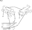
- FIG. 1 shows a first exemplary embodiment of the clamping ring according to the invention in two perspective views and a cross-sectional view.
- the clamping ring includes a hollow cylindrical portion 1 arranged around a central axis of the clamping ring for receiving a hose or pipe and six arms 4 which protrude parallel to the central axis of the clamping ring from a first open end of the hollow cylindrical portion 1.
- the arms 4 are spring arms, which are elastically bendable towards the center axis of the clamping ring and / or away from the center axis of the clamping ring.
- the arms 4 comprise a group of three first arms and a group of three second arms, the second arms being shorter than the first arms.
- stopper members 2 for preventing a full penetration of a hose or pipe through the hollow cylindrical portion 1 are arranged.
- the stop elements 2 are arranged on the inside of the hollow cylindrical portion 1 along the edge of the second open end of the hollow cylindrical portion 1.
- the hollow cylindrical portion 1 in this case has three large and three small recesses at its second open end, wherein the stop elements 2 are arranged in areas without recesses.
- the six boundary elements 5, 7 comprise a group of three first boundary elements 5 and a group of three second boundary elements 7, wherein the first boundary elements 5 are farther from the second end of the hollow cylindrical section 1 than the second boundary elements 7. Between the group of first boundary elements 5 and the group of second limiting elements 7, a receiving area for a sessteckende fastening nut is arranged.
- the first limiting elements 5 are arranged on a side remote from the center axis of the clamping ring side of the first (longer) arms and the second limiting elements 7 are arranged on a side remote from the central axis of the clamping ring side of the second (shorter) arms.
- the first (longer) arms with the first limiting elements 5 arranged thereon are designed as clip elements which are elastically bendable in the direction of the center axis of the clamping ring and have a chamfer on a side facing away from the center axis of the clamping ring.
- the second (shorter) arms have, on a side facing the center axis of the clamping ring, in each case a claw element 3 with an edge pointing in the direction of the second open end of the hollow cylindrical section 1.
- the second arms on the central axis of the clamping ring side facing each have a chamfer, wherein the edge of the snap element 3 is in each case at the end of the chamfer.
- anti-rotation elements 6 are arranged, which are designed as parallel to the central axis of the clamping ring extending webs.
- FIG. 2 shows the first exemplary embodiment of the clamping ring according to the invention FIG. 1 in combination with a fastening nut 8 and a base body 9 in two different views.
- FIG. 1 On the right is a perspective view with the three individual elements separated from each other (ie clamping ring, mounting nut 8 and base 9) shown.
- the main body 9 comprises a cone for attaching a hose or pipe and arranged around the cone housing portion. Between the cone and the housing section is an annular gap, in which at least a part of the hollow cylindrical portion 1 of the clamping ring is arranged.
- the fastening nut 8 is mounted in the receiving area, which is located between the group of first limiting elements 5 and the group of second limiting elements 7, on the clamping ring.
- the fastening nut 8 has an internal thread with which it is screwed onto an external thread of the housing section 9.
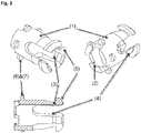
- FIG. 3 shows a second exemplary embodiment of the clamping ring according to the invention in two perspective views and a cross-sectional view.
- the clamping ring here contains a hollow cylindrical portion 1 arranged around a central axis of the clamping ring for receiving a hose or pipeline and three arms 4 which protrude parallel to the center axis of the clamping ring from a first open end of the hollow cylindrical portion 1.
- the arms 4 are spring arms, which are elastically bendable towards the center axis of the clamping ring and / or away from the center axis of the clamping ring.
- stopper members 2 for preventing a full penetration of a hose or pipe through the hollow cylindrical portion 1 are arranged.
- the stop elements 2 are arranged on the inside of the hollow cylindrical portion 1 along the edge of the second open end of the hollow cylindrical portion 1.
- the hollow cylindrical portion 1 in this case has three recesses at its second open end, wherein the stop elements 2 are arranged in areas without recesses.
- the eight boundary elements 5, 7 comprise a group of three first boundary elements 5 and a group of five second boundary elements 7, wherein the first limiting elements 5 are further away from the second end of the hollow cylindrical portion 1 than the second limiting elements 7. Between the group of first limiting elements 5 and the group of second limiting elements 7, a receiving area for a mounting nut personallysteck is arranged.
- the first limiting elements 5 are arranged on a side facing away from the central axis of the clamping ring side of the arms 4 and the second limiting elements 7 are arranged on the outside of the hollow cylindrical portion 1.
- the arms 4 with the first limiting elements 5 arranged thereon are designed as clip elements which are elastically bendable in the direction of the center axis of the clamping ring and have a chamfer on a side remote from the center axis of the clamping ring.
- the arms 4 each have on a side facing the center axis of the clamping ring a claw element 3 with an edge pointing in the direction of the second open end of the hollow cylindrical section 1.
- the arms 4 each have a chamfer on the side facing the central axis of the clamping ring, wherein the edge of the claw element 3 is in each case at the end of the chamfer.
- the second limiting elements 7 are designed so that they simultaneously serve as anti-rotation elements 6.
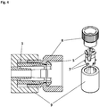
- FIG. 4 shows the second exemplary embodiment of the clamping ring according to the invention in combination with a fastening nut 8 and a base body 9 in two different views.
- On the right is a perspective view with the three individual elements separated from each other (ie clamping ring, mounting nut 8 and base 9) shown.
- On the left is shown a cross-sectional view of the three composite elements, which represent in this form another exemplary embodiment of the clamping device according to the invention.
- the main body 9 comprises a cone for attaching a hose or pipe and arranged around the cone housing portion.
- annular gap Between the cone and the housing portion is an annular gap in which at least a part of the hollow cylindrical portion 1 of the clamping ring is arranged.
- the fastening nut 8 is mounted in the receiving area, which is located between the group of first limiting elements 5 and the group of second limiting elements 7, on the clamping ring.
- the fastening nut 8 has an external thread with which it is screwed into an internal thread of the housing section 9.
Landscapes
- Engineering & Computer Science (AREA)
- General Engineering & Computer Science (AREA)
- Mechanical Engineering (AREA)
- Clamps And Clips (AREA)
Applications Claiming Priority (1)
| Application Number | Priority Date | Filing Date | Title |
|---|---|---|---|
| DE102018205397.9A DE102018205397A1 (de) | 2018-04-10 | 2018-04-10 | Klemmring für Schlauchverbindungen, den Klemmring umfassende Klemmvorrichtung für Schlauchverbindungen sowie die Klemmvorrichtung umfassende Schlauchverbindung |
Publications (2)
| Publication Number | Publication Date |
|---|---|
| EP3553361A1 true EP3553361A1 (fr) | 2019-10-16 |
| EP3553361B1 EP3553361B1 (fr) | 2023-07-12 |
Family
ID=66092057
Family Applications (1)
| Application Number | Title | Priority Date | Filing Date |
|---|---|---|---|
| EP19167045.4A Active EP3553361B1 (fr) | 2018-04-10 | 2019-04-03 | Bague de serrage pour raccordement de tuyau, dispositif de serrage comportant la bague de serrage pour raccordements de tuyau ainsi que dispositif de serrage comportant un raccordement de tuyau |
Country Status (2)
| Country | Link |
|---|---|
| EP (1) | EP3553361B1 (fr) |
| DE (1) | DE102018205397A1 (fr) |
Citations (4)
| Publication number | Priority date | Publication date | Assignee | Title |
|---|---|---|---|---|
| JPH06207694A (ja) * | 1993-01-11 | 1994-07-26 | Toyo Fuitsutengu Kk | 樹脂管用継手のシールリング及び該シールリングを用いた樹脂管と継手本体との接続構造 |
| EP1788292A2 (fr) * | 2005-11-22 | 2007-05-23 | GARDENA Manufacturing GmbH | Raccordement pour un tuyau flexible |
| EP1918625A1 (fr) * | 2005-07-04 | 2008-05-07 | Nippon Flex Co., Ltd | Connecteur destiné à raccorder des tuyaux |
| EP2447586A1 (fr) * | 2010-10-26 | 2012-05-02 | Michael Meier | Raccord pour tuyau |
Family Cites Families (6)
| Publication number | Priority date | Publication date | Assignee | Title |
|---|---|---|---|---|
| DE4211498A1 (de) | 1992-04-06 | 1993-10-07 | Em Technik Gmbh Armaturenbau | Rohrverschraubung für relativ starre Schläuche |
| WO1994015135A1 (fr) * | 1992-12-18 | 1994-07-07 | Dayco Products, Inc. | Structure de tuyau flexible, raccord destine a ce dernier et procede de fabrication |
| DE19540279A1 (de) * | 1995-10-28 | 1997-04-30 | Balfo Verwaltungs Anstalt | Anschlußstück für Profilrohre, Profilstutzen, Wellschläuche oder dergleichen Stränge |
| DE19721179C1 (de) | 1997-05-21 | 1998-10-08 | Em Technik Gmbh Armaturenbau | Schlauchverschraubung |
| DE102006011617A1 (de) * | 2006-03-14 | 2007-09-20 | Norma Germany Gmbh | Verbindungsanordnung zur Verbindung eines Rohrstutzens mit einem Schlauch |
| DE102013015455B4 (de) * | 2013-09-18 | 2021-07-01 | Mira Kunststofftechnik Gmbh | Rohrverschraubung |
-
2018
- 2018-04-10 DE DE102018205397.9A patent/DE102018205397A1/de not_active Withdrawn
-
2019
- 2019-04-03 EP EP19167045.4A patent/EP3553361B1/fr active Active
Patent Citations (4)
| Publication number | Priority date | Publication date | Assignee | Title |
|---|---|---|---|---|
| JPH06207694A (ja) * | 1993-01-11 | 1994-07-26 | Toyo Fuitsutengu Kk | 樹脂管用継手のシールリング及び該シールリングを用いた樹脂管と継手本体との接続構造 |
| EP1918625A1 (fr) * | 2005-07-04 | 2008-05-07 | Nippon Flex Co., Ltd | Connecteur destiné à raccorder des tuyaux |
| EP1788292A2 (fr) * | 2005-11-22 | 2007-05-23 | GARDENA Manufacturing GmbH | Raccordement pour un tuyau flexible |
| EP2447586A1 (fr) * | 2010-10-26 | 2012-05-02 | Michael Meier | Raccord pour tuyau |
Also Published As
| Publication number | Publication date |
|---|---|
| EP3553361B1 (fr) | 2023-07-12 |
| DE102018205397A1 (de) | 2019-10-10 |
Similar Documents
| Publication | Publication Date | Title |
|---|---|---|
| DE69212793T2 (de) | Verbindungsvorrichtung für Teile eines Fluid-Verteilungssystems, besagte Teile und System | |
| DE69919724T2 (de) | Kupplungsvorrichtung | |
| EP2211976B1 (fr) | Dispositif de raccordement d'un conduit souple d'aspiration | |
| EP2649689B1 (fr) | Dispositif pour fixer un câble sur un raccord de départ de câble | |
| DE60011359T2 (de) | Vorrichtung zum Verbinden von einem Leitungsende mit einem Anschlussteil | |
| DE19828059C2 (de) | Anschlußarmatur mit einem durch Schlitze in Haltezungen aufgeteilten Befestigungsvorsprung | |
| EP2807417B1 (fr) | Procédé pour relier une pièce de raccordement à un conduit thermo-isolé | |
| DE102011009536A1 (de) | Spannelement | |
| EP2582889A1 (fr) | Robinetterie de distribution d'eau à rotule | |
| EP1030097A2 (fr) | Dispositif de raccordement ayant un corps d'armature à fixation rotative | |
| DE4430114C2 (de) | Anschlußstück für einen Kunststoffschlauch einer Badezimmer-Handbrause | |
| DE102013210922B4 (de) | Verbindungselement und Verbindungsanordnung | |
| WO2009086877A1 (fr) | Unité d'engagement à emboîter et à engager sur un boulon fileté | |
| WO2014154716A1 (fr) | Adaptateur de raccord de tuyau et élément de robinetterie sanitaire | |
| EP1722146B1 (fr) | Dispositif de connexion pour tuyaux avec élément annulaire | |
| DE4035008A1 (de) | Ventilpistole fuer ein hochdruckreinigungsgeraet sowie schlauchkupplung, insbesondere fuer eine solche ventilpistole | |
| DE19529189A1 (de) | Anschlußstück | |
| EP3322923B1 (fr) | Raccord de conduite sanitaire | |
| EP2334968A1 (fr) | Accouplement à verrouillage | |
| EP3553361B1 (fr) | Bague de serrage pour raccordement de tuyau, dispositif de serrage comportant la bague de serrage pour raccordements de tuyau ainsi que dispositif de serrage comportant un raccordement de tuyau | |
| DE69800336T2 (de) | Schnellkupplungsmittel zum Anschliessen von Schläuchen mit unterschiedlichen Durchmessern | |
| DE69006285T2 (de) | Verbindungsstück für Kunststoffrohre und Montageverfahren. | |
| DE102007054025A1 (de) | Steckkupplung für Rohre, Kupplungseinrichtung mit wenigstens zwei solchen Steckkupplungen | |
| EP1740873A1 (fr) | Raccord pour tuyaux flexibles | |
| DE19712171C1 (de) | Klemmverbinder |
Legal Events
| Date | Code | Title | Description |
|---|---|---|---|
| PUAI | Public reference made under article 153(3) epc to a published international application that has entered the european phase |
Free format text: ORIGINAL CODE: 0009012 |
|
| STAA | Information on the status of an ep patent application or granted ep patent |
Free format text: STATUS: THE APPLICATION HAS BEEN PUBLISHED |
|
| AK | Designated contracting states |
Kind code of ref document: A1 Designated state(s): AL AT BE BG CH CY CZ DE DK EE ES FI FR GB GR HR HU IE IS IT LI LT LU LV MC MK MT NL NO PL PT RO RS SE SI SK SM TR |
|
| AX | Request for extension of the european patent |
Extension state: BA ME |
|
| STAA | Information on the status of an ep patent application or granted ep patent |
Free format text: STATUS: REQUEST FOR EXAMINATION WAS MADE |
|
| 17P | Request for examination filed |
Effective date: 20200330 |
|
| RBV | Designated contracting states (corrected) |
Designated state(s): AL AT BE BG CH CY CZ DE DK EE ES FI FR GB GR HR HU IE IS IT LI LT LU LV MC MK MT NL NO PL PT RO RS SE SI SK SM TR |
|
| STAA | Information on the status of an ep patent application or granted ep patent |
Free format text: STATUS: EXAMINATION IS IN PROGRESS |
|
| 17Q | First examination report despatched |
Effective date: 20201007 |
|
| RAP3 | Party data changed (applicant data changed or rights of an application transferred) |
Owner name: WMF GMBH |
|
| GRAP | Despatch of communication of intention to grant a patent |
Free format text: ORIGINAL CODE: EPIDOSNIGR1 |
|
| STAA | Information on the status of an ep patent application or granted ep patent |
Free format text: STATUS: GRANT OF PATENT IS INTENDED |
|
| INTG | Intention to grant announced |
Effective date: 20230203 |
|
| GRAS | Grant fee paid |
Free format text: ORIGINAL CODE: EPIDOSNIGR3 |
|
| GRAA | (expected) grant |
Free format text: ORIGINAL CODE: 0009210 |
|
| STAA | Information on the status of an ep patent application or granted ep patent |
Free format text: STATUS: THE PATENT HAS BEEN GRANTED |
|
| P01 | Opt-out of the competence of the unified patent court (upc) registered |
Effective date: 20230525 |
|
| AK | Designated contracting states |
Kind code of ref document: B1 Designated state(s): AL AT BE BG CH CY CZ DE DK EE ES FI FR GB GR HR HU IE IS IT LI LT LU LV MC MK MT NL NO PL PT RO RS SE SI SK SM TR |
|
| REG | Reference to a national code |
Ref country code: CH Ref legal event code: EP |
|
| REG | Reference to a national code |
Ref country code: DE Ref legal event code: R096 Ref document number: 502019008457 Country of ref document: DE |
|
| REG | Reference to a national code |
Ref country code: IE Ref legal event code: FG4D Free format text: LANGUAGE OF EP DOCUMENT: GERMAN |
|
| REG | Reference to a national code |
Ref country code: NL Ref legal event code: FP |
|
| REG | Reference to a national code |
Ref country code: LT Ref legal event code: MG9D |
|
| PG25 | Lapsed in a contracting state [announced via postgrant information from national office to epo] |
Ref country code: GR Free format text: LAPSE BECAUSE OF FAILURE TO SUBMIT A TRANSLATION OF THE DESCRIPTION OR TO PAY THE FEE WITHIN THE PRESCRIBED TIME-LIMIT Effective date: 20231013 |
|
| PG25 | Lapsed in a contracting state [announced via postgrant information from national office to epo] |
Ref country code: ES Free format text: LAPSE BECAUSE OF FAILURE TO SUBMIT A TRANSLATION OF THE DESCRIPTION OR TO PAY THE FEE WITHIN THE PRESCRIBED TIME-LIMIT Effective date: 20230712 |
|
| PG25 | Lapsed in a contracting state [announced via postgrant information from national office to epo] |
Ref country code: IS Free format text: LAPSE BECAUSE OF FAILURE TO SUBMIT A TRANSLATION OF THE DESCRIPTION OR TO PAY THE FEE WITHIN THE PRESCRIBED TIME-LIMIT Effective date: 20231112 |
|
| PG25 | Lapsed in a contracting state [announced via postgrant information from national office to epo] |
Ref country code: SE Free format text: LAPSE BECAUSE OF FAILURE TO SUBMIT A TRANSLATION OF THE DESCRIPTION OR TO PAY THE FEE WITHIN THE PRESCRIBED TIME-LIMIT Effective date: 20230712 Ref country code: RS Free format text: LAPSE BECAUSE OF FAILURE TO SUBMIT A TRANSLATION OF THE DESCRIPTION OR TO PAY THE FEE WITHIN THE PRESCRIBED TIME-LIMIT Effective date: 20230712 Ref country code: PT Free format text: LAPSE BECAUSE OF FAILURE TO SUBMIT A TRANSLATION OF THE DESCRIPTION OR TO PAY THE FEE WITHIN THE PRESCRIBED TIME-LIMIT Effective date: 20231113 Ref country code: NO Free format text: LAPSE BECAUSE OF FAILURE TO SUBMIT A TRANSLATION OF THE DESCRIPTION OR TO PAY THE FEE WITHIN THE PRESCRIBED TIME-LIMIT Effective date: 20231012 Ref country code: LV Free format text: LAPSE BECAUSE OF FAILURE TO SUBMIT A TRANSLATION OF THE DESCRIPTION OR TO PAY THE FEE WITHIN THE PRESCRIBED TIME-LIMIT Effective date: 20230712 Ref country code: LT Free format text: LAPSE BECAUSE OF FAILURE TO SUBMIT A TRANSLATION OF THE DESCRIPTION OR TO PAY THE FEE WITHIN THE PRESCRIBED TIME-LIMIT Effective date: 20230712 Ref country code: IS Free format text: LAPSE BECAUSE OF FAILURE TO SUBMIT A TRANSLATION OF THE DESCRIPTION OR TO PAY THE FEE WITHIN THE PRESCRIBED TIME-LIMIT Effective date: 20231112 Ref country code: HR Free format text: LAPSE BECAUSE OF FAILURE TO SUBMIT A TRANSLATION OF THE DESCRIPTION OR TO PAY THE FEE WITHIN THE PRESCRIBED TIME-LIMIT Effective date: 20230712 Ref country code: GR Free format text: LAPSE BECAUSE OF FAILURE TO SUBMIT A TRANSLATION OF THE DESCRIPTION OR TO PAY THE FEE WITHIN THE PRESCRIBED TIME-LIMIT Effective date: 20231013 Ref country code: FI Free format text: LAPSE BECAUSE OF FAILURE TO SUBMIT A TRANSLATION OF THE DESCRIPTION OR TO PAY THE FEE WITHIN THE PRESCRIBED TIME-LIMIT Effective date: 20230712 Ref country code: ES Free format text: LAPSE BECAUSE OF FAILURE TO SUBMIT A TRANSLATION OF THE DESCRIPTION OR TO PAY THE FEE WITHIN THE PRESCRIBED TIME-LIMIT Effective date: 20230712 |
|
| PG25 | Lapsed in a contracting state [announced via postgrant information from national office to epo] |
Ref country code: PL Free format text: LAPSE BECAUSE OF FAILURE TO SUBMIT A TRANSLATION OF THE DESCRIPTION OR TO PAY THE FEE WITHIN THE PRESCRIBED TIME-LIMIT Effective date: 20230712 |
|
| REG | Reference to a national code |
Ref country code: DE Ref legal event code: R097 Ref document number: 502019008457 Country of ref document: DE |
|
| PG25 | Lapsed in a contracting state [announced via postgrant information from national office to epo] |
Ref country code: SM Free format text: LAPSE BECAUSE OF FAILURE TO SUBMIT A TRANSLATION OF THE DESCRIPTION OR TO PAY THE FEE WITHIN THE PRESCRIBED TIME-LIMIT Effective date: 20230712 Ref country code: RO Free format text: LAPSE BECAUSE OF FAILURE TO SUBMIT A TRANSLATION OF THE DESCRIPTION OR TO PAY THE FEE WITHIN THE PRESCRIBED TIME-LIMIT Effective date: 20230712 Ref country code: EE Free format text: LAPSE BECAUSE OF FAILURE TO SUBMIT A TRANSLATION OF THE DESCRIPTION OR TO PAY THE FEE WITHIN THE PRESCRIBED TIME-LIMIT Effective date: 20230712 Ref country code: DK Free format text: LAPSE BECAUSE OF FAILURE TO SUBMIT A TRANSLATION OF THE DESCRIPTION OR TO PAY THE FEE WITHIN THE PRESCRIBED TIME-LIMIT Effective date: 20230712 Ref country code: CZ Free format text: LAPSE BECAUSE OF FAILURE TO SUBMIT A TRANSLATION OF THE DESCRIPTION OR TO PAY THE FEE WITHIN THE PRESCRIBED TIME-LIMIT Effective date: 20230712 Ref country code: SK Free format text: LAPSE BECAUSE OF FAILURE TO SUBMIT A TRANSLATION OF THE DESCRIPTION OR TO PAY THE FEE WITHIN THE PRESCRIBED TIME-LIMIT Effective date: 20230712 |
|
| PLBE | No opposition filed within time limit |
Free format text: ORIGINAL CODE: 0009261 |
|
| STAA | Information on the status of an ep patent application or granted ep patent |
Free format text: STATUS: NO OPPOSITION FILED WITHIN TIME LIMIT |
|
| 26N | No opposition filed |
Effective date: 20240415 |
|
| PG25 | Lapsed in a contracting state [announced via postgrant information from national office to epo] |
Ref country code: SI Free format text: LAPSE BECAUSE OF FAILURE TO SUBMIT A TRANSLATION OF THE DESCRIPTION OR TO PAY THE FEE WITHIN THE PRESCRIBED TIME-LIMIT Effective date: 20230712 |
|
| PG25 | Lapsed in a contracting state [announced via postgrant information from national office to epo] |
Ref country code: BG Free format text: LAPSE BECAUSE OF FAILURE TO SUBMIT A TRANSLATION OF THE DESCRIPTION OR TO PAY THE FEE WITHIN THE PRESCRIBED TIME-LIMIT Effective date: 20230712 |
|
| PG25 | Lapsed in a contracting state [announced via postgrant information from national office to epo] |
Ref country code: MC Free format text: LAPSE BECAUSE OF FAILURE TO SUBMIT A TRANSLATION OF THE DESCRIPTION OR TO PAY THE FEE WITHIN THE PRESCRIBED TIME-LIMIT Effective date: 20230712 |
|
| PG25 | Lapsed in a contracting state [announced via postgrant information from national office to epo] |
Ref country code: MC Free format text: LAPSE BECAUSE OF FAILURE TO SUBMIT A TRANSLATION OF THE DESCRIPTION OR TO PAY THE FEE WITHIN THE PRESCRIBED TIME-LIMIT Effective date: 20230712 Ref country code: BG Free format text: LAPSE BECAUSE OF FAILURE TO SUBMIT A TRANSLATION OF THE DESCRIPTION OR TO PAY THE FEE WITHIN THE PRESCRIBED TIME-LIMIT Effective date: 20230712 |
|
| PG25 | Lapsed in a contracting state [announced via postgrant information from national office to epo] |
Ref country code: LU Free format text: LAPSE BECAUSE OF NON-PAYMENT OF DUE FEES Effective date: 20240403 |
|
| GBPC | Gb: european patent ceased through non-payment of renewal fee |
Effective date: 20240403 |
|
| REG | Reference to a national code |
Ref country code: BE Ref legal event code: MM Effective date: 20240430 |
|
| PG25 | Lapsed in a contracting state [announced via postgrant information from national office to epo] |
Ref country code: LU Free format text: LAPSE BECAUSE OF NON-PAYMENT OF DUE FEES Effective date: 20240403 |
|
| PG25 | Lapsed in a contracting state [announced via postgrant information from national office to epo] |
Ref country code: BE Free format text: LAPSE BECAUSE OF NON-PAYMENT OF DUE FEES Effective date: 20240430 |
|
| PG25 | Lapsed in a contracting state [announced via postgrant information from national office to epo] |
Ref country code: GB Free format text: LAPSE BECAUSE OF NON-PAYMENT OF DUE FEES Effective date: 20240403 |
|
| PG25 | Lapsed in a contracting state [announced via postgrant information from national office to epo] |
Ref country code: FR Free format text: LAPSE BECAUSE OF NON-PAYMENT OF DUE FEES Effective date: 20240430 |
|
| PG25 | Lapsed in a contracting state [announced via postgrant information from national office to epo] |
Ref country code: GB Free format text: LAPSE BECAUSE OF NON-PAYMENT OF DUE FEES Effective date: 20240403 Ref country code: FR Free format text: LAPSE BECAUSE OF NON-PAYMENT OF DUE FEES Effective date: 20240430 Ref country code: BE Free format text: LAPSE BECAUSE OF NON-PAYMENT OF DUE FEES Effective date: 20240430 |
|
| PGFP | Annual fee paid to national office [announced via postgrant information from national office to epo] |
Ref country code: NL Payment date: 20250325 Year of fee payment: 7 |
|
| PG25 | Lapsed in a contracting state [announced via postgrant information from national office to epo] |
Ref country code: IE Free format text: LAPSE BECAUSE OF NON-PAYMENT OF DUE FEES Effective date: 20240403 |
|
| PGFP | Annual fee paid to national office [announced via postgrant information from national office to epo] |
Ref country code: AT Payment date: 20250321 Year of fee payment: 7 |
|
| PG25 | Lapsed in a contracting state [announced via postgrant information from national office to epo] |
Ref country code: CY Free format text: LAPSE BECAUSE OF FAILURE TO SUBMIT A TRANSLATION OF THE DESCRIPTION OR TO PAY THE FEE WITHIN THE PRESCRIBED TIME-LIMIT; INVALID AB INITIO Effective date: 20190403 |
|
| PG25 | Lapsed in a contracting state [announced via postgrant information from national office to epo] |
Ref country code: HU Free format text: LAPSE BECAUSE OF FAILURE TO SUBMIT A TRANSLATION OF THE DESCRIPTION OR TO PAY THE FEE WITHIN THE PRESCRIBED TIME-LIMIT; INVALID AB INITIO Effective date: 20190403 |
|
| PG25 | Lapsed in a contracting state [announced via postgrant information from national office to epo] |
Ref country code: TR Free format text: LAPSE BECAUSE OF FAILURE TO SUBMIT A TRANSLATION OF THE DESCRIPTION OR TO PAY THE FEE WITHIN THE PRESCRIBED TIME-LIMIT Effective date: 20230712 |
|
| REG | Reference to a national code |
Ref country code: CH Ref legal event code: U11 Free format text: ST27 STATUS EVENT CODE: U-0-0-U10-U11 (AS PROVIDED BY THE NATIONAL OFFICE) Effective date: 20260504 |
|
| PGFP | Annual fee paid to national office [announced via postgrant information from national office to epo] |
Ref country code: IT Payment date: 20260409 Year of fee payment: 8 |
|
| PGFP | Annual fee paid to national office [announced via postgrant information from national office to epo] |
Ref country code: DE Payment date: 20260416 Year of fee payment: 8 |
|
| PGFP | Annual fee paid to national office [announced via postgrant information from national office to epo] |
Ref country code: CH Payment date: 20260504 Year of fee payment: 8 |