EP3553392B1 - Appareil de cuisson - Google Patents
Appareil de cuisson Download PDFInfo
- Publication number
- EP3553392B1 EP3553392B1 EP18203028.8A EP18203028A EP3553392B1 EP 3553392 B1 EP3553392 B1 EP 3553392B1 EP 18203028 A EP18203028 A EP 18203028A EP 3553392 B1 EP3553392 B1 EP 3553392B1
- Authority
- EP
- European Patent Office
- Prior art keywords
- steam
- water
- supply pipe
- return
- cooking appliance
- Prior art date
- Legal status (The legal status is an assumption and is not a legal conclusion. Google has not performed a legal analysis and makes no representation as to the accuracy of the status listed.)
- Active
Links
Images




Classifications
-
- F—MECHANICAL ENGINEERING; LIGHTING; HEATING; WEAPONS; BLASTING
- F24—HEATING; RANGES; VENTILATING
- F24C—DOMESTIC STOVES OR RANGES ; DETAILS OF DOMESTIC STOVES OR RANGES, OF GENERAL APPLICATION
- F24C15/00—Details
- F24C15/20—Removing cooking fumes
- F24C15/2007—Removing cooking fumes from oven cavities
-
- F—MECHANICAL ENGINEERING; LIGHTING; HEATING; WEAPONS; BLASTING
- F24—HEATING; RANGES; VENTILATING
- F24C—DOMESTIC STOVES OR RANGES ; DETAILS OF DOMESTIC STOVES OR RANGES, OF GENERAL APPLICATION
- F24C15/00—Details
- F24C15/32—Arrangements of ducts for hot gases, e.g. in or around baking ovens
- F24C15/322—Arrangements of ducts for hot gases, e.g. in or around baking ovens with forced circulation
- F24C15/327—Arrangements of ducts for hot gases, e.g. in or around baking ovens with forced circulation with air moisturising
-
- A—HUMAN NECESSITIES
- A47—FURNITURE; DOMESTIC ARTICLES OR APPLIANCES; COFFEE MILLS; SPICE MILLS; SUCTION CLEANERS IN GENERAL
- A47J—KITCHEN EQUIPMENT; COFFEE MILLS; SPICE MILLS; APPARATUS FOR MAKING BEVERAGES
- A47J27/00—Cooking-vessels
- A47J27/04—Cooking-vessels for cooking food in steam; Devices for extracting fruit juice by means of steam ; Vacuum cooking vessels
-
- A—HUMAN NECESSITIES
- A47—FURNITURE; DOMESTIC ARTICLES OR APPLIANCES; COFFEE MILLS; SPICE MILLS; SUCTION CLEANERS IN GENERAL
- A47J—KITCHEN EQUIPMENT; COFFEE MILLS; SPICE MILLS; APPARATUS FOR MAKING BEVERAGES
- A47J36/00—Parts, details or accessories of cooking-vessels
- A47J36/38—Parts, details or accessories of cooking-vessels for withdrawing or condensing cooking vapors from cooking utensils
-
- F—MECHANICAL ENGINEERING; LIGHTING; HEATING; WEAPONS; BLASTING
- F22—STEAM GENERATION
- F22B—METHODS OF STEAM GENERATION; STEAM BOILERS
- F22B1/00—Methods of steam generation characterised by form of heating method
- F22B1/28—Methods of steam generation characterised by form of heating method in boilers heated electrically
- F22B1/284—Methods of steam generation characterised by form of heating method in boilers heated electrically with water in reservoirs
- F22B1/285—Methods of steam generation characterised by form of heating method in boilers heated electrically with water in reservoirs the water being fed by a pump to the reservoirs
-
- F—MECHANICAL ENGINEERING; LIGHTING; HEATING; WEAPONS; BLASTING
- F22—STEAM GENERATION
- F22D—PREHEATING, OR ACCUMULATING PREHEATED, FEED-WATER FOR STEAM GENERATION; FEED-WATER SUPPLY FOR STEAM GENERATION; CONTROLLING WATER LEVEL FOR STEAM GENERATION; AUXILIARY DEVICES FOR PROMOTING WATER CIRCULATION WITHIN STEAM BOILERS
- F22D11/00—Feed-water supply not provided for in other main groups
- F22D11/02—Arrangements of feed-water pumps
- F22D11/06—Arrangements of feed-water pumps for returning condensate to boiler
-
- A—HUMAN NECESSITIES
- A47—FURNITURE; DOMESTIC ARTICLES OR APPLIANCES; COFFEE MILLS; SPICE MILLS; SUCTION CLEANERS IN GENERAL
- A47J—KITCHEN EQUIPMENT; COFFEE MILLS; SPICE MILLS; APPARATUS FOR MAKING BEVERAGES
- A47J27/00—Cooking-vessels
- A47J27/04—Cooking-vessels for cooking food in steam; Devices for extracting fruit juice by means of steam ; Vacuum cooking vessels
- A47J2027/043—Cooking-vessels for cooking food in steam; Devices for extracting fruit juice by means of steam ; Vacuum cooking vessels for cooking food in steam
Definitions
- the present specification relates to a cooking appliance.
- the cooking appliance refers to an appliance for cooking food using heat of a heating source.
- the cooking appliance may include a heating source for heating food contained in a cooking chamber.
- the cooking appliance may include a plurality of heating sources.
- the plurality of heating sources may include an electric heater, a magnetron, a steam generator, etc.
- Korean Patent Laid-Open Publication No. 10-2011-0109661 which is a prior art document, discloses a stream generator.
- the steam generator of the prior art document includes a heating space for receiving water for steam generation, a water supply port for supplying the water for steam generation to the heating space, a steam heater for heating the water for steam generation stored in the heating space to generate steam, a steam discharge port for discharging the steam heated by the steam heater, and a drain port for discharging the water for steam generation stored in the heating space to the outside of the heating space such that the water for steam generation supplied to the heating space through the water supply port is maintained at a predetermined water level.
- the water for steam generation exceeds the predetermined water level, the water for steam generation is discharged to the outside through the drain port, thereby preventing the water for steam generation from overflowing to the inside of the cooking chamber while the water for steam generation is heated.
- US 2012/199015 A1 discloses a steam generation unit and steam cooking device using same.
- the steam generation device is placed at a lower portion of a side wall of a heating chamber.
- a steam jet-out part is placed upper than the steam generation device of the side wall of the heating chamber with a distance from the steam generation device.
- GB 2 377 483 A discloses a steam generator for a cooking device.
- the generator has a boiler chamber with a frusto-conical wall that diverges toward a base.
- a heating device such as an electrical coil, is used to heat the water externally from the chamber. The heating may alternatively be provided by hot combustion gases or by induction.
- a water inlet supplies water to the bottom of the chamber which also forms a pump sump. The evaporated water, together with entrained water, exits via a steam outlet. The entrained water may be removed by a water separator before it is returned to the boiler chamber via a pump and pipe.
- the internal surface of the boiler chamber wall may have a glass, ceramic, or metal surface.
- a soil-resistant pump may be provided to allow removal of boiler scale.
- KR 2011 0109661 A discloses a steam generator and cooker comprising the same.
- EP 2 369 227 A2 discloses a steam generation unit for a domestic appliance and method for operating same.
- JP 2010 121803 A discloses a steam generating device capable of suppressing delivering of water droplet to a delivered section without increasing a size of the device.
- the present embodiment provides a cooking appliance capable of preventing water discharged with steam from being supplied to a cooking chamber in a steam generation process.
- the present embodiment provides a cooking appliance capable of returning water discharged to a steam supply pipe together with steam to a steam generator.
- the present embodiment provides a cooking appliance capable of preventing water in a heating chamber from flowing back to a return pipe.
- the present embodiment provides a cooking appliance capable of returning water of a steam supply pipe by a simple structure.
- a cooking appliance includes a main body including a cooking chamber, a steam generator including a steam heater for generating steam for heating food contained in the cooking chamber, a water tank configured to store water to be supplied to the steam generator, a water supply pipe configured to supply the water of the water tank to the steam generator, a steam supply pipe configured to supply the steam generated in the steam generator to the cooking chamber, and a return pipe connected to the steam supply pipe and the steam generator to return, to the steam generator, the water between the steam and the water discharged to the steam supply pipe.
- the steam generator includes a heating chamber in which water is stored.
- the steam generator includes a water supply part configured to supply water to the heating chamber.
- the steam generator includes a return part connected to the return pipe.
- the return part may be located at a position higher than a maximum water level in the heating chamber
- the return part may be located at a position higher than the water supply part.
- the steam generator further includes a partitioning part located at a position lower than the return part and which may further be located at a position higher than the water supply part.
- the steam generator may include: a first body; and a second body coupled to the first body to form the heating chamber.
- the partitioning part may protrude from any one of the first body and the second body and may have an end spaced apart from the other of the first body and the second body.
- the water supply part may be located in the first body.
- the return part may be located in the second body.
- the partitioning part may protrude from the second body.
- the steam generator may further include a steam discharge part configured to discharge steam.
- the return part may be located at a position lower than the steam discharge part.
- the return part may be located closer to the water supply part than the steam discharge part.
- the steam supply pipe may be bent once or more and may include a portion bent to extend upward.
- the return part may be connected to a bent portion of the steam supply pipe.
- the steam supply pipe may include a first supply pipe and a second supply pipe bent from the first supply pipe to extend upward.
- the first supply pipe may be a part of the steam supply pipe connected to the steam generator.
- the first supply pipe may be a part of the steam supply pipe into which the steam discharged from the steam generator flows.
- the second supply pipe may be a part of the steam supply pipe connected to the main body.
- the second supply pipe may be bent from the first supply pipe to extend upward.
- the first supply pipe and the second supply pipe may extend to form an angle with respect to each other. In other words, the first and second supply pipes may be inclined with respect to each other so that the steam supply pipe is bent.
- the return pipe may extend from the second supply pipe parallel or in a line therewith.
- the return pipe may extend downward at a boundary between the first supply pipe and the second supply pipe.
- An inner diameter of the return pipe may be less than an inner diameter of the second supply pipe.
- the inner diameter of the return pipe may be in a range of 1/5 to 1/4 of the inner diameter of the second supply pipe.
- the cooking appliance may further comprise a water supply pump connected to the water supply pipe.
- the water of the return pipe is returned to the steam generator at the time of operating the water supply pump.
- first, second, A, B, (a) and (b) may be used.
- Each of the terms is merely used to distinguish the corresponding component from other components, and does not delimit an essence, an order or a sequence of the corresponding component. It should be understood that when one component is “connected”, “coupled” or “joined” to another component, the former may be directly connected or jointed to the latter or may be “connected”, coupled” or “joined” to the latter with a third component interposed therebetween.
- FIG. 1 is a view schematically showing the inside of a cooking chamber of a cooking appliance according to an embodiment of the present invention
- FIG. 2 is a view showing a state in which a steam generator and a water tank are installed in a cooking appliance according to an embodiment of the present invention
- FIG. 3 is an exploded perspective view of a steam generator according to an embodiment of the present invention
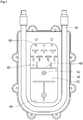
- FIG. 4 is a view showing the internal structure of a steam generator according to an embodiment of the present invention.
- the cooking appliance 1 may include a main body 10.
- the main body 10 may include a cooking chamber 12.
- the cooking appliance 1 may further include a door connected to the main body 10 to open or close the cooking chamber 12.
- the cooking appliance 1 may further include an upper cooking part 20 for heating food independently of food contained in the cooking chamber 12 according to the type of the cooking appliance 1.
- FIG. 2 shows an upper cooking part including a burner, for example.
- the cooking appliance 1 may include a plurality of heating sources in order to cook the food contained in the cooking chamber 12.
- the plurality of heating sources may include different types of heating sources.
- the plurality of heating sources may include, for example, a heater 21.
- the heater 21 may be, for example, located at an upper side in the cooking chamber 12 and may supply heat to the upper side of the cooking chamber 12.
- the heater 21 may be located at the upper side of the cooking chamber 12 outside the cooking chamber 12.
- an opening, through which heat passes, may be formed in the upper wall of the cooking chamber 12.
- a transmission part may be provided in the upper wall of the cooking chamber 12.
- an additional heater may be further provided at the lower side of the cooking chamber 12.
- the plurality of heating sources may further include a convection heater (not shown) configuring a convection device 24.
- the convection device 24 may include a convection fan. By the convection fan, air in the cooking chamber 21 may flow to the convection heater, thereby being heated and then supplied to the cooking chamber 12.
- the plurality of heating sources may further include a steam generator 40 for heating water to generate steam.
- the cooking appliance 1 may further include a water tank 30 for supplying water to the steam generator 40.
- the water tank 30 may be disposed at a position higher than the steam generator 40 in the main body 10.
- the water tank 30 may be located above the cooking chamber 12.
- the cooking appliance 1 may further include a water supply pipe 31 for supplying water of the water tank 30 to the steam generator 40, a water supply pump 32 connected to the water supply pipe 31, a drain pipe 36 for discharging water of the steam generator 40 and a drainage pump 35 connected to the drain pipe 36.
- the drain pipe 36 may be connected to the water tank 30. Accordingly, the water of the water tank 30 may be supplied to the steam generator 40, and the water of the steam generator 40 may be drained and returned to the water tank 30.
- the steam generator 40 may include a first body 410 and a second body 420 coupled to the first body 410.
- the first body 410 and the second body 420 may form a heating chamber 411.
- a steam heater 430 may be embedded in any one of the first body 410 and the second body 420.
- the steam heater 430 is installed in the first body 410.
- a water supply part 412 for supplying water to the heating chamber 411 may be provided in any one of the first body 410 and the second body 420.
- the water supply part 412 may communicate with the water supply pipe 31.
- the water supply part 412 may be provided in the first body 410, for example.
- a steam discharge part 418 for discharging steam generated by the heating chamber 411 may be provided in any one of the first body 410 and the second body 420.
- the steam discharge part 418 is provided in the first body 410, for example.
- a drain part 424 for discharging water of the heating chamber 411 may be provided in any one of the first body 410 and the second body 420.
- the drain part 424 is provided in the second body 420.
- the water supply part 412 may be located at a position higher than the drain part 424 and located at a position lower than the steam discharge part 418.
- the water supply part 412 may be located at the center of the heating chamber 411
- the steam discharge part 418 may be located at the upper side of the heating chamber 411
- the drain part 424 may be located at the lower side of the heating chamber 411.
- a return part 426 for returning water to the heating chamber 411 may be provided in any one of the first body 410 and the second body 420.
- Water discharged from the steam generator 40 together with steam may be returned to the return part 426.
- the return part 426 may be located in the second body 420.
- the return part 426 may communicate with the heating chamber 411, and may be located at a position higher than the water supply part 412 in the heating chamber 411.
- the return part 426 may be located at a position higher than the maximum water level of the heating chamber 411 in the heating chamber 411.
- first body 410 and the second body 420 may further include a partitioning part 428 located in a region between the return part 426 and the water supply part 412.
- the partitioning part 428 is located at a position lower than the return part 426 and located at a position higher than the water supply part 412.
- the partitioning part 428 may protrude from one of the first body 410 and the second body 420 toward the other thereof, and may have an end thereof disposed to be spaced apart from the other of the first body and the second body.
- the partitioning part 428 may protrude from the second body 420, for example, in a horizontal direction and the end (see 428a of FIG. 6 ) thereof may be spaced apart from the first body 410.
- a gap between the end 428a of the partitioning part 428 and the first body 410 may provide a passage, through which steam passes.
- the return part 426 may be located at a position lower than the steam discharge part 418. When the return part 426 is located at the position lower than the steam discharge part 418, it is possible to prevent the water returned by the return part 426 from being directly discharged to the steam discharge part 418.
- the return part 426 may be located closer to the water supply part 412 than the steam discharge part 418.
- the steam generator 40 may further include a mounting bracket 470 for mounting the steam generator 40 to the main body 10.
- the mounting bracket 470 may be, for example, coupled to the first body 410.
- the mounting bracket 470 may include a steam guide pipe 472 for guiding the steam discharged from the steam discharge part 418.
- the cooking appliance 1 may further include a steam supply pipe 440 connected to the steam guide pipe 472 to supply the steam generated by the steam generator 40 to the cooking chamber 12.
- the steam supply pipe 440 may be connected to a steam supply port 14.
- the steam supply port 14 is, for example, coupled to the main body 10 to finally supply steam to the cooking chamber 12.
- the steam supply port 14 may be exposed to the cooking chamber 12.
- the steam supply pipe 440 may be directly connected to the main body 10 and the end of the steam supply pipe 440 may include the steam supply port 14.
- the steam supply pipe 440 is bent once or more to guide the steam discharged from the steam discharge part 418 upward and to supply the steam to the cooking chamber 12.
- a return pipe 450 for returning water between the steam and water discharged to the steam supply pipe 440 may be connected to the steam supply pipe 440.
- the return pipe 450 may be connected to the return part 426.
- FIG. 5 is a view showing a state in which a return pipe is connected to a steam generator, according to an embodiment of the present invention
- FIG. 6 is a cross-sectional view showing a state in which a return pipe is connected to a steam generator and a steam supply pipe according to an embodiment of the present invention.
- the steam supply pipe 440 may include a first supply pipe 442 connected to the steam guide pipe 472 and a second supply pipe 444 bent from an end of the first supply pipe 442.
- the second supply pipe 444 may be bent from the end of the first supply pipe 442 to extend upward.
- the steam discharged to the first supply pipe 442 flows upward after the direction of the steam is changed at a boundary 443 between the first supply pipe 442 and the second supply pipe 444.
- the steam and the water may be separated at the boundary 443 between the first supply pipe 442 and the second supply pipe 444 by a difference in specific gravity (or weight) between water and steam.
- the return pipe 450 may be connected to the boundary 443 between the first supply pipe 442 and the second supply pipe 444 (an upwardly bent portion of the steam supply pipe 440).
- the inner diameter of the return pipe 450 may be in a range of 1/5 to 1/4 of the inner diameter of the second supply pipe 444, such that the water is returned to the return pipe 450 and the steam is prevented from flowing to the return pipe 450.
- the steam may flow to the return pipe 450.
- the steam is returned to the heating chamber 411 along the return pipe 450 to reduce the amount of steam supplied to the cooking chamber 12, thereby increasing a cooking time.
- the amount of water returned to the return pipe 450 is reduced, thereby supplying water to the cooking chamber 12 through the second supply pipe 444.
- the inner diameter of the return pipe 450 is less than 1/5 of the inner diameter of the second supply pipe 444, water may not be returned to the return pipe 450.
- water may be returned to the return pipe 450. Since the pressure of the heating chamber 411 is similar to that of the steam supply pipe 440, the water of the return pipe 450 may not flow into the heating chamber 411 and may remain in the return pipe 450.
- the water supply pump 32 is repeatedly turned on and off, thereby periodically supplying water to the heating chamber 411.
- the inside of the heating chamber 411 has high pressure and a high temperature by operation of the steam heater 430.
- the pressure of the heating chamber 411 becomes lower than that of the return pipe 450.
- the water existing in the return pipe 450 may be returned to the heating chamber 411.
- the return pipe 450 may be extended downward to be connected to the return part 426 of the steam generator 40, for example.
- the water of the steam supply pipe 440 may be returned to the return pipe 450, thereby preventing water from being supplied to the cooking chamber 12.
Landscapes
- Engineering & Computer Science (AREA)
- Mechanical Engineering (AREA)
- General Engineering & Computer Science (AREA)
- Food Science & Technology (AREA)
- Thermal Sciences (AREA)
- Physics & Mathematics (AREA)
- Chemical & Material Sciences (AREA)
- Combustion & Propulsion (AREA)
- Water Supply & Treatment (AREA)
- Life Sciences & Earth Sciences (AREA)
- Sustainable Development (AREA)
- Sustainable Energy (AREA)
- Electric Ovens (AREA)
- Commercial Cooking Devices (AREA)
Claims (15)
- Appareil de cuisson comportant :un corps principal (10) incluant une chambre de cuisson (12) ;un générateur de vapeur (40) incluant un dispositif de chauffage à la vapeur (430) configuré pour générer de la vapeur pour chauffer un aliment contenu dans la chambre cuisson (12), une chambre de chauffage (411) pour stocker de l'eau, et une partie d'alimentation en eau (412) configurée pour fournir de l'eau à la chambre de chauffage (411) ;un réservoir d'eau (30) configuré pour stocker l'eau devant être fournie au générateur de vapeur (40) ;un tuyau d'alimentation en eau (31) configuré pour fournir l'eau du réservoir d'eau (30) au générateur de vapeur (40) ;un tuyau d'alimentation en vapeur (440) configuré pour fournir la vapeur générée dans le générateur de vapeur (40) à la chambre de cuisson (12) ; etun tuyau de retour (450) raccordé au tuyau d'alimentation en vapeur (440) et au générateur de vapeur (40) pour renvoyer, au générateur de vapeur (40), l'eau évacuée vers le tuyau d'alimentation en vapeur (440) ;dans lequel le générateur de vapeur (40) inclut une partie de retour (426) raccordée au tuyau de retour (450),caractérisé en ce que le générateur de vapeur (40) inclut en outre une partie de séparation (428) située à une position plus basse que la partie de retour (426).
- Appareil de cuisson selon la revendication 1, dans lequel la partie de retour (426) est située à une position plus haute qu'un niveau d'eau maximal dans la chambre de chauffage (411).
- Appareil de cuisson selon la revendication 2, dans lequel la partie de retour (426) est située à une position plus haute que la partie d'alimentation en eau (412).
- Appareil de cuisson selon la revendication 2 ou 3, dans lequel la partie de séparation (428) est située à une position plus haute que la partie d'alimentation en eau (412).
- Appareil de cuisson selon l'une quelconque des revendications 1 à 4, dans lequel le générateur de vapeur (40) inclut :un premier corps (410) ; etun second corps (420) couplé au premier corps (410) pour former la chambre de chauffage (411),dans lequel la partie de séparation (428) fait saillie à partir d'un corps quelconque parmi le premier corps (410) et le second corps (420) et a une extrémité (428a) espacée de l'autre corps parmi le premier corps (410) et le second corps (420).
- Appareil de cuisson selon la revendication 5, dans lequel la partie de retour (426) est située dans le second corps (420), et dans lequel la partie de séparation (428) fait saillie à partir du second corps (420).
- Appareil de cuisson selon la revendication 6, dans lequel la partie d'alimentation en eau (412) est située dans le premier corps (410).
- Appareil de cuisson selon l'une quelconque des revendications 1 à 7, dans lequel le générateur de vapeur (40) inclut en outre une partie d'évacuation de vapeur (418) configurée pour évacuer de la vapeur, et
dans lequel la partie de retour (426) est située à une position plus basse que la partie d'évacuation de vapeur (418). - Appareil de cuisson selon la revendication 8, dans lequel la partie de retour (426) est située plus près de la partie d'alimentation en eau (412) que la partie d'évacuation de vapeur (418).
- Appareil de cuisson selon l'une quelconque des revendications précédentes, dans lequel le tuyau d'alimentation en vapeur (440) est coudé pour inclure une portion coudée, et
dans lequel la partie de retour (426) est raccordée à une portion coudée du tuyau d'alimentation en vapeur (440). - Appareil de cuisson selon la revendication 10, dans lequel le tuyau d'alimentation en vapeur (440) inclut un premier tuyau d'alimentation (442) raccordé au générateur de vapeur, et un second tuyau d'alimentation (444) raccordé entre le premier tuyau d'alimentation (442) et la chambre de cuisson (12), le premier tuyau d'alimentation (442) et le second tuyau d'alimentation (444) s'étendant pour former un angle l'un par rapport à l'autre et
dans lequel le tuyau de retour (450) est raccordé au tuyau d'alimentation en vapeur (440) entre le premier tuyau d'alimentation (442) et le second tuyau d'alimentation (444). - Appareil de cuisson selon la revendication 10 ou 11, dans lequel le tuyau de retour (450) s'étend à partir du second tuyau d'alimentation (444) de manière alignée avec celui-ci.
- Appareil de cuisson selon l'une quelconque des revendications précédentes, dans lequel un diamètre intérieur du tuyau de retour (450) est inférieur à un diamètre intérieur du tuyau d'alimentation en vapeur (440).
- Appareil de cuisson selon la revendication 13, dans lequel le diamètre intérieur du tuyau de retour (450) est dans un intervalle de 1/5 à 1/4 du diamètre intérieur du tuyau d'alimentation en vapeur (440).
- Appareil de cuisson selon l'une quelconque des revendications précédentes, comportant en outre une pompe d'alimentation en eau (32) raccordée au tuyau d'alimentation en eau (31) et configurée pour renvoyer l'eau du tuyau de retour (450) au générateur de vapeur (40).
Applications Claiming Priority (1)
| Application Number | Priority Date | Filing Date | Title |
|---|---|---|---|
| KR1020180042651A KR102060356B1 (ko) | 2018-04-12 | 2018-04-12 | 조리기기 |
Publications (2)
| Publication Number | Publication Date |
|---|---|
| EP3553392A1 EP3553392A1 (fr) | 2019-10-16 |
| EP3553392B1 true EP3553392B1 (fr) | 2020-12-02 |
Family
ID=64082910
Family Applications (1)
| Application Number | Title | Priority Date | Filing Date |
|---|---|---|---|
| EP18203028.8A Active EP3553392B1 (fr) | 2018-04-12 | 2018-10-29 | Appareil de cuisson |
Country Status (3)
| Country | Link |
|---|---|
| US (1) | US10871291B2 (fr) |
| EP (1) | EP3553392B1 (fr) |
| KR (1) | KR102060356B1 (fr) |
Families Citing this family (7)
| Publication number | Priority date | Publication date | Assignee | Title |
|---|---|---|---|---|
| US10047961B2 (en) * | 2013-09-27 | 2018-08-14 | Lg Electronics Inc. | Steam generator and cooking appliance |
| CN113647800B (zh) * | 2017-05-25 | 2022-07-15 | 三星电子株式会社 | 蒸汽烹调器 |
| KR102385208B1 (ko) * | 2017-07-28 | 2022-04-11 | 엘지이노텍 주식회사 | 냉온장치 |
| DE202018006410U1 (de) | 2017-08-09 | 2020-04-23 | Sharkninja Operating Llc | Kochgerät und Komponenten davon |
| WO2020176477A1 (fr) | 2019-02-25 | 2020-09-03 | Sharkninja Operating Llc | Système de cuisson avec protection |
| US20190254476A1 (en) | 2019-02-25 | 2019-08-22 | Sharkninja Operating Llc | Cooking device and components thereof |
| US11647861B2 (en) | 2020-03-30 | 2023-05-16 | Sharkninja Operating Llc | Cooking device and components thereof |
Family Cites Families (9)
| Publication number | Priority date | Publication date | Assignee | Title |
|---|---|---|---|---|
| DE10109251C1 (de) * | 2001-02-26 | 2002-08-08 | Rational Ag | Dampferzeuger, insbesondere für ein Gargerät |
| JP2010121803A (ja) * | 2008-11-17 | 2010-06-03 | Hoshizaki Electric Co Ltd | 蒸気発生装置 |
| KR101724696B1 (ko) | 2010-03-31 | 2017-04-18 | 엘지전자 주식회사 | 스팀 발생장치 및 이를 포함하는 조리기기 |
| KR101206657B1 (ko) | 2009-04-06 | 2012-11-29 | 엘지전자 주식회사 | 스팀발생장치 및 이를 포함하는 조리기기 |
| JP4707758B2 (ja) * | 2009-10-08 | 2011-06-22 | シャープ株式会社 | 蒸気発生ユニットおよびそれを用いた蒸気調理器 |
| DE102009055144A1 (de) * | 2009-12-22 | 2011-06-30 | BSH Bosch und Siemens Hausgeräte GmbH, 81739 | Dampferzeugungseinheit für ein Haushaltsgerät und Verfahren zum Erzeugen von Wasserdampf |
| KR101394959B1 (ko) | 2012-07-12 | 2014-05-14 | 오재원 | 홍삼 제조용 증숙장치 |
| EP3225139B1 (fr) * | 2016-03-30 | 2020-04-29 | E.G.O. ELEKTRO-GERÄTEBAU GmbH | Dispositif d'evaporation pour l'eau |
| KR102455063B1 (ko) * | 2018-04-04 | 2022-10-14 | 엘지전자 주식회사 | 조리기기 및 그의 제어방법 |
-
2018
- 2018-04-12 KR KR1020180042651A patent/KR102060356B1/ko active Active
- 2018-10-29 EP EP18203028.8A patent/EP3553392B1/fr active Active
-
2019
- 2019-03-05 US US16/292,865 patent/US10871291B2/en active Active
Non-Patent Citations (1)
| Title |
|---|
| None * |
Also Published As
| Publication number | Publication date |
|---|---|
| KR20190119332A (ko) | 2019-10-22 |
| EP3553392A1 (fr) | 2019-10-16 |
| KR102060356B1 (ko) | 2019-12-30 |
| US20190316783A1 (en) | 2019-10-17 |
| US10871291B2 (en) | 2020-12-22 |
Similar Documents
| Publication | Publication Date | Title |
|---|---|---|
| EP3553392B1 (fr) | Appareil de cuisson | |
| EP3575685B1 (fr) | Générateur de vapeur et appareil de cuisson le comprenant | |
| EP3575694B1 (fr) | Appareil de cuisson comprenant un générateur de vapeur | |
| EP1654931B1 (fr) | Générateur de vapeur pour un four à vapeur | |
| RU2531415C2 (ru) | Варочное устройство | |
| CN101152049B (zh) | 蒸汽发生器和具有其的加热烹饪设备 | |
| US8648281B2 (en) | Steam generating device and cooking device | |
| US11166467B2 (en) | Cooking appliance | |
| JP5315000B2 (ja) | 蒸気発生装置 | |
| US20100230396A1 (en) | Oven Steam Generator Systems and Methods | |
| WO2014136431A1 (fr) | Appareil de cuisson chauffant | |
| CN110290706A (zh) | 蒸汽发生器及与其相关的蒸汽烹饪系统 | |
| KR101724696B1 (ko) | 스팀 발생장치 및 이를 포함하는 조리기기 | |
| JP2012122675A (ja) | 加熱調理器 | |
| JP5722918B2 (ja) | 急速湯沸かし器およびその湯沸かし器を備える家庭電化製品 | |
| KR20090082991A (ko) | 전기 보일러 | |
| KR102490845B1 (ko) | 스팀 공급 장치 및 이를 구비한 조리기기 | |
| JP2010038374A (ja) | 加熱調理器 | |
| JP6546406B2 (ja) | 蒸気発生装置 | |
| EP2899460B1 (fr) | Unité de chauffage, dispositif de chauffage et procédé de génération de vapeur de liquide et de gaz de chauffage dans une unité de chauffage | |
| JP5548012B2 (ja) | 加熱調理器 | |
| KR20260023719A (ko) | 스팀 컨벡션 오븐의 스팀 발생기 | |
| JP2014194338A (ja) | 加熱調理器 | |
| KR20200101734A (ko) | 조리기기 | |
| KR20250141698A (ko) | 액체 재료 기화 장치, 액체 재료 기화 시스템 |
Legal Events
| Date | Code | Title | Description |
|---|---|---|---|
| PUAI | Public reference made under article 153(3) epc to a published international application that has entered the european phase |
Free format text: ORIGINAL CODE: 0009012 |
|
| STAA | Information on the status of an ep patent application or granted ep patent |
Free format text: STATUS: REQUEST FOR EXAMINATION WAS MADE |
|
| 17P | Request for examination filed |
Effective date: 20181029 |
|
| AK | Designated contracting states |
Kind code of ref document: A1 Designated state(s): AL AT BE BG CH CY CZ DE DK EE ES FI FR GB GR HR HU IE IS IT LI LT LU LV MC MK MT NL NO PL PT RO RS SE SI SK SM TR |
|
| AX | Request for extension of the european patent |
Extension state: BA ME |
|
| GRAP | Despatch of communication of intention to grant a patent |
Free format text: ORIGINAL CODE: EPIDOSNIGR1 |
|
| STAA | Information on the status of an ep patent application or granted ep patent |
Free format text: STATUS: GRANT OF PATENT IS INTENDED |
|
| RIC1 | Information provided on ipc code assigned before grant |
Ipc: F24C 15/32 20060101AFI20200417BHEP |
|
| INTG | Intention to grant announced |
Effective date: 20200511 |
|
| GRAS | Grant fee paid |
Free format text: ORIGINAL CODE: EPIDOSNIGR3 |
|
| GRAJ | Information related to disapproval of communication of intention to grant by the applicant or resumption of examination proceedings by the epo deleted |
Free format text: ORIGINAL CODE: EPIDOSDIGR1 |
|
| GRAL | Information related to payment of fee for publishing/printing deleted |
Free format text: ORIGINAL CODE: EPIDOSDIGR3 |
|
| STAA | Information on the status of an ep patent application or granted ep patent |
Free format text: STATUS: REQUEST FOR EXAMINATION WAS MADE |
|
| GRAR | Information related to intention to grant a patent recorded |
Free format text: ORIGINAL CODE: EPIDOSNIGR71 |
|
| STAA | Information on the status of an ep patent application or granted ep patent |
Free format text: STATUS: GRANT OF PATENT IS INTENDED |
|
| INTC | Intention to grant announced (deleted) | ||
| GRAA | (expected) grant |
Free format text: ORIGINAL CODE: 0009210 |
|
| STAA | Information on the status of an ep patent application or granted ep patent |
Free format text: STATUS: THE PATENT HAS BEEN GRANTED |
|
| INTG | Intention to grant announced |
Effective date: 20200929 |
|
| AK | Designated contracting states |
Kind code of ref document: B1 Designated state(s): AL AT BE BG CH CY CZ DE DK EE ES FI FR GB GR HR HU IE IS IT LI LT LU LV MC MK MT NL NO PL PT RO RS SE SI SK SM TR |
|
| REG | Reference to a national code |
Ref country code: GB Ref legal event code: FG4D |
|
| REG | Reference to a national code |
Ref country code: AT Ref legal event code: REF Ref document number: 1341344 Country of ref document: AT Kind code of ref document: T Effective date: 20201215 Ref country code: CH Ref legal event code: EP |
|
| REG | Reference to a national code |
Ref country code: IE Ref legal event code: FG4D |
|
| REG | Reference to a national code |
Ref country code: DE Ref legal event code: R096 Ref document number: 602018010377 Country of ref document: DE |
|
| PG25 | Lapsed in a contracting state [announced via postgrant information from national office to epo] |
Ref country code: FI Free format text: LAPSE BECAUSE OF FAILURE TO SUBMIT A TRANSLATION OF THE DESCRIPTION OR TO PAY THE FEE WITHIN THE PRESCRIBED TIME-LIMIT Effective date: 20201202 Ref country code: RS Free format text: LAPSE BECAUSE OF FAILURE TO SUBMIT A TRANSLATION OF THE DESCRIPTION OR TO PAY THE FEE WITHIN THE PRESCRIBED TIME-LIMIT Effective date: 20201202 Ref country code: GR Free format text: LAPSE BECAUSE OF FAILURE TO SUBMIT A TRANSLATION OF THE DESCRIPTION OR TO PAY THE FEE WITHIN THE PRESCRIBED TIME-LIMIT Effective date: 20210303 Ref country code: NO Free format text: LAPSE BECAUSE OF FAILURE TO SUBMIT A TRANSLATION OF THE DESCRIPTION OR TO PAY THE FEE WITHIN THE PRESCRIBED TIME-LIMIT Effective date: 20210302 |
|
| REG | Reference to a national code |
Ref country code: NL Ref legal event code: MP Effective date: 20201202 |
|
| REG | Reference to a national code |
Ref country code: AT Ref legal event code: MK05 Ref document number: 1341344 Country of ref document: AT Kind code of ref document: T Effective date: 20201202 |
|
| PG25 | Lapsed in a contracting state [announced via postgrant information from national office to epo] |
Ref country code: BG Free format text: LAPSE BECAUSE OF FAILURE TO SUBMIT A TRANSLATION OF THE DESCRIPTION OR TO PAY THE FEE WITHIN THE PRESCRIBED TIME-LIMIT Effective date: 20210302 Ref country code: LV Free format text: LAPSE BECAUSE OF FAILURE TO SUBMIT A TRANSLATION OF THE DESCRIPTION OR TO PAY THE FEE WITHIN THE PRESCRIBED TIME-LIMIT Effective date: 20201202 Ref country code: PL Free format text: LAPSE BECAUSE OF FAILURE TO SUBMIT A TRANSLATION OF THE DESCRIPTION OR TO PAY THE FEE WITHIN THE PRESCRIBED TIME-LIMIT Effective date: 20201202 Ref country code: SE Free format text: LAPSE BECAUSE OF FAILURE TO SUBMIT A TRANSLATION OF THE DESCRIPTION OR TO PAY THE FEE WITHIN THE PRESCRIBED TIME-LIMIT Effective date: 20201202 |
|
| PG25 | Lapsed in a contracting state [announced via postgrant information from national office to epo] |
Ref country code: HR Free format text: LAPSE BECAUSE OF FAILURE TO SUBMIT A TRANSLATION OF THE DESCRIPTION OR TO PAY THE FEE WITHIN THE PRESCRIBED TIME-LIMIT Effective date: 20201202 Ref country code: NL Free format text: LAPSE BECAUSE OF FAILURE TO SUBMIT A TRANSLATION OF THE DESCRIPTION OR TO PAY THE FEE WITHIN THE PRESCRIBED TIME-LIMIT Effective date: 20201202 |
|
| REG | Reference to a national code |
Ref country code: LT Ref legal event code: MG9D |
|
| PG25 | Lapsed in a contracting state [announced via postgrant information from national office to epo] |
Ref country code: SM Free format text: LAPSE BECAUSE OF FAILURE TO SUBMIT A TRANSLATION OF THE DESCRIPTION OR TO PAY THE FEE WITHIN THE PRESCRIBED TIME-LIMIT Effective date: 20201202 Ref country code: SK Free format text: LAPSE BECAUSE OF FAILURE TO SUBMIT A TRANSLATION OF THE DESCRIPTION OR TO PAY THE FEE WITHIN THE PRESCRIBED TIME-LIMIT Effective date: 20201202 Ref country code: EE Free format text: LAPSE BECAUSE OF FAILURE TO SUBMIT A TRANSLATION OF THE DESCRIPTION OR TO PAY THE FEE WITHIN THE PRESCRIBED TIME-LIMIT Effective date: 20201202 Ref country code: CZ Free format text: LAPSE BECAUSE OF FAILURE TO SUBMIT A TRANSLATION OF THE DESCRIPTION OR TO PAY THE FEE WITHIN THE PRESCRIBED TIME-LIMIT Effective date: 20201202 Ref country code: LT Free format text: LAPSE BECAUSE OF FAILURE TO SUBMIT A TRANSLATION OF THE DESCRIPTION OR TO PAY THE FEE WITHIN THE PRESCRIBED TIME-LIMIT Effective date: 20201202 Ref country code: PT Free format text: LAPSE BECAUSE OF FAILURE TO SUBMIT A TRANSLATION OF THE DESCRIPTION OR TO PAY THE FEE WITHIN THE PRESCRIBED TIME-LIMIT Effective date: 20210405 Ref country code: RO Free format text: LAPSE BECAUSE OF FAILURE TO SUBMIT A TRANSLATION OF THE DESCRIPTION OR TO PAY THE FEE WITHIN THE PRESCRIBED TIME-LIMIT Effective date: 20201202 |
|
| PG25 | Lapsed in a contracting state [announced via postgrant information from national office to epo] |
Ref country code: AT Free format text: LAPSE BECAUSE OF FAILURE TO SUBMIT A TRANSLATION OF THE DESCRIPTION OR TO PAY THE FEE WITHIN THE PRESCRIBED TIME-LIMIT Effective date: 20201202 |
|
| REG | Reference to a national code |
Ref country code: DE Ref legal event code: R097 Ref document number: 602018010377 Country of ref document: DE |
|
| PG25 | Lapsed in a contracting state [announced via postgrant information from national office to epo] |
Ref country code: IS Free format text: LAPSE BECAUSE OF FAILURE TO SUBMIT A TRANSLATION OF THE DESCRIPTION OR TO PAY THE FEE WITHIN THE PRESCRIBED TIME-LIMIT Effective date: 20210402 |
|
| PLBE | No opposition filed within time limit |
Free format text: ORIGINAL CODE: 0009261 |
|
| STAA | Information on the status of an ep patent application or granted ep patent |
Free format text: STATUS: NO OPPOSITION FILED WITHIN TIME LIMIT |
|
| PG25 | Lapsed in a contracting state [announced via postgrant information from national office to epo] |
Ref country code: AL Free format text: LAPSE BECAUSE OF FAILURE TO SUBMIT A TRANSLATION OF THE DESCRIPTION OR TO PAY THE FEE WITHIN THE PRESCRIBED TIME-LIMIT Effective date: 20201202 |
|
| 26N | No opposition filed |
Effective date: 20210903 |
|
| PG25 | Lapsed in a contracting state [announced via postgrant information from national office to epo] |
Ref country code: DK Free format text: LAPSE BECAUSE OF FAILURE TO SUBMIT A TRANSLATION OF THE DESCRIPTION OR TO PAY THE FEE WITHIN THE PRESCRIBED TIME-LIMIT Effective date: 20201202 Ref country code: SI Free format text: LAPSE BECAUSE OF FAILURE TO SUBMIT A TRANSLATION OF THE DESCRIPTION OR TO PAY THE FEE WITHIN THE PRESCRIBED TIME-LIMIT Effective date: 20201202 |
|
| PG25 | Lapsed in a contracting state [announced via postgrant information from national office to epo] |
Ref country code: ES Free format text: LAPSE BECAUSE OF FAILURE TO SUBMIT A TRANSLATION OF THE DESCRIPTION OR TO PAY THE FEE WITHIN THE PRESCRIBED TIME-LIMIT Effective date: 20201202 |
|
| REG | Reference to a national code |
Ref country code: CH Ref legal event code: PL |
|
| PG25 | Lapsed in a contracting state [announced via postgrant information from national office to epo] |
Ref country code: IS Free format text: LAPSE BECAUSE OF FAILURE TO SUBMIT A TRANSLATION OF THE DESCRIPTION OR TO PAY THE FEE WITHIN THE PRESCRIBED TIME-LIMIT Effective date: 20210402 |
|
| REG | Reference to a national code |
Ref country code: BE Ref legal event code: MM Effective date: 20211031 |
|
| PG25 | Lapsed in a contracting state [announced via postgrant information from national office to epo] |
Ref country code: MC Free format text: LAPSE BECAUSE OF FAILURE TO SUBMIT A TRANSLATION OF THE DESCRIPTION OR TO PAY THE FEE WITHIN THE PRESCRIBED TIME-LIMIT Effective date: 20201202 |
|
| PG25 | Lapsed in a contracting state [announced via postgrant information from national office to epo] |
Ref country code: LU Free format text: LAPSE BECAUSE OF NON-PAYMENT OF DUE FEES Effective date: 20211029 Ref country code: BE Free format text: LAPSE BECAUSE OF NON-PAYMENT OF DUE FEES Effective date: 20211031 |
|
| PG25 | Lapsed in a contracting state [announced via postgrant information from national office to epo] |
Ref country code: LI Free format text: LAPSE BECAUSE OF NON-PAYMENT OF DUE FEES Effective date: 20211031 Ref country code: CH Free format text: LAPSE BECAUSE OF NON-PAYMENT OF DUE FEES Effective date: 20211031 |
|
| PG25 | Lapsed in a contracting state [announced via postgrant information from national office to epo] |
Ref country code: IE Free format text: LAPSE BECAUSE OF NON-PAYMENT OF DUE FEES Effective date: 20211029 |
|
| GBPC | Gb: european patent ceased through non-payment of renewal fee |
Effective date: 20221029 |
|
| PG25 | Lapsed in a contracting state [announced via postgrant information from national office to epo] |
Ref country code: CY Free format text: LAPSE BECAUSE OF FAILURE TO SUBMIT A TRANSLATION OF THE DESCRIPTION OR TO PAY THE FEE WITHIN THE PRESCRIBED TIME-LIMIT Effective date: 20201202 |
|
| PG25 | Lapsed in a contracting state [announced via postgrant information from national office to epo] |
Ref country code: HU Free format text: LAPSE BECAUSE OF FAILURE TO SUBMIT A TRANSLATION OF THE DESCRIPTION OR TO PAY THE FEE WITHIN THE PRESCRIBED TIME-LIMIT; INVALID AB INITIO Effective date: 20181029 |
|
| PG25 | Lapsed in a contracting state [announced via postgrant information from national office to epo] |
Ref country code: GB Free format text: LAPSE BECAUSE OF NON-PAYMENT OF DUE FEES Effective date: 20221029 |
|
| PG25 | Lapsed in a contracting state [announced via postgrant information from national office to epo] |
Ref country code: MK Free format text: LAPSE BECAUSE OF FAILURE TO SUBMIT A TRANSLATION OF THE DESCRIPTION OR TO PAY THE FEE WITHIN THE PRESCRIBED TIME-LIMIT Effective date: 20201202 |
|
| PG25 | Lapsed in a contracting state [announced via postgrant information from national office to epo] |
Ref country code: TR Free format text: LAPSE BECAUSE OF FAILURE TO SUBMIT A TRANSLATION OF THE DESCRIPTION OR TO PAY THE FEE WITHIN THE PRESCRIBED TIME-LIMIT Effective date: 20201202 |
|
| PG25 | Lapsed in a contracting state [announced via postgrant information from national office to epo] |
Ref country code: MT Free format text: LAPSE BECAUSE OF FAILURE TO SUBMIT A TRANSLATION OF THE DESCRIPTION OR TO PAY THE FEE WITHIN THE PRESCRIBED TIME-LIMIT Effective date: 20201202 |
|
| PGFP | Annual fee paid to national office [announced via postgrant information from national office to epo] |
Ref country code: IT Payment date: 20250909 Year of fee payment: 8 |
|
| PGFP | Annual fee paid to national office [announced via postgrant information from national office to epo] |
Ref country code: FR Payment date: 20250909 Year of fee payment: 8 |
|
| PGFP | Annual fee paid to national office [announced via postgrant information from national office to epo] |
Ref country code: DE Payment date: 20250908 Year of fee payment: 8 |