EP3553403B1 - Système cvc et procédé de fonctionnement d'un système cvc - Google Patents
Système cvc et procédé de fonctionnement d'un système cvc Download PDFInfo
- Publication number
- EP3553403B1 EP3553403B1 EP19168141.0A EP19168141A EP3553403B1 EP 3553403 B1 EP3553403 B1 EP 3553403B1 EP 19168141 A EP19168141 A EP 19168141A EP 3553403 B1 EP3553403 B1 EP 3553403B1
- Authority
- EP
- European Patent Office
- Prior art keywords
- demand
- supply side
- zone
- subsystem
- hvac system
- Prior art date
- Legal status (The legal status is an assumption and is not a legal conclusion. Google has not performed a legal analysis and makes no representation as to the accuracy of the status listed.)
- Active
Links
Images


Classifications
-
- F—MECHANICAL ENGINEERING; LIGHTING; HEATING; WEAPONS; BLASTING
- F24—HEATING; RANGES; VENTILATING
- F24F—AIR-CONDITIONING; AIR-HUMIDIFICATION; VENTILATION; USE OF AIR CURRENTS FOR SCREENING
- F24F11/00—Control or safety arrangements
- F24F11/62—Control or safety arrangements characterised by the type of control or by internal processing, e.g. using fuzzy logic, adaptive control or estimation of values
- F24F11/63—Electronic processing
-
- F—MECHANICAL ENGINEERING; LIGHTING; HEATING; WEAPONS; BLASTING
- F24—HEATING; RANGES; VENTILATING
- F24F—AIR-CONDITIONING; AIR-HUMIDIFICATION; VENTILATION; USE OF AIR CURRENTS FOR SCREENING
- F24F11/00—Control or safety arrangements
- F24F11/70—Control systems characterised by their outputs; Constructional details thereof
- F24F11/80—Control systems characterised by their outputs; Constructional details thereof for controlling the temperature of the supplied air
- F24F11/83—Control systems characterised by their outputs; Constructional details thereof for controlling the temperature of the supplied air by controlling the supply of heat-exchange fluids to heat-exchangers
-
- F—MECHANICAL ENGINEERING; LIGHTING; HEATING; WEAPONS; BLASTING
- F24—HEATING; RANGES; VENTILATING
- F24F—AIR-CONDITIONING; AIR-HUMIDIFICATION; VENTILATION; USE OF AIR CURRENTS FOR SCREENING
- F24F2140/00—Control inputs relating to system states
- F24F2140/50—Load
Definitions
- HVAC heating, ventilation, and air conditioning
- a typical HVAC system in, for example, a commercial building may include chillers, cooling towers, air handling units (AHUs) and fan coil units (FCUs).
- a Building Management System (BMS) controls the devices by providing setpoints or schedules.
- the FCUs on the zones in the building can be controlled by the BMS directly or locally by a thermostat.
- the desired temperature setpoints of the zones are set in the BMS or on the local thermostats; ii. the refrigeration system starts to work to supply chilled water (chilled water) at a set temperature; iii. opens the valve on the FCU to allow chilled water flow to cool the room to the desired temperature; IV. the chiller receives return chilled water at a higher temperature; and V.
- the difference between the supply (flow) and return temperature defines the cooling load of the building and the working mode of the chiller.
- the information is also used to plan chiller staging when the load already exceeds the threshold capacity.
- a buffer is provided in the chiller staging process to avoid unwanted staging (clocking) due to fluctuation in return chilled water temperature.
- the buffer time induces a delay between the increasing demand and the cooling water supply. This will slow down the system response.
- the WO2016/148651 A1 discloses a method of operating a building environmental management system (BEMS) comprising: a) obtaining zone environment sensor data and zone setpoints for two or more zones in a building; b) Calculation of a request for minimum supply of cooling/heating air for each area to meet the zone setpoints; c) transmission of the request for each zone to a scheduler; d) receiving the requests for each area and the energy efficiency data for one or more components of the BEMS from the planner; e) calculation of an air supply strategy that includes allocation of cooling/heating air supply for each zone in order to minimize the energy consumption of one or more components while meeting all zone setpoint requirements; and f) controlling the BEMS to make the assignment of step e) to each zone.
- BEMS building environmental management
- the US2008/028780 A1 discloses a method for controlling the start-up operation of an air conditioner having a compressor and an indoor and an outdoor fan, comprising the steps of: a) calculating the indoor cooling/heating load based on an indoor temperature, an outdoor temperature and a difference between the indoor temperature and a target temperature; b) calculating a reference operating frequency of the compressor using the calculated indoor cooling/heating load; c) driving the indoor and outdoor fans for a first period to thereby adjust the pressure balance between an indoor and an outdoor pressure when an operation start signal of the air conditioner is inputted; d) driving the compressor for a preset period of time while incrementally increasing the operating frequency of the compressor, the operating frequency of the compressor being lower than the reference operating frequency throughout the preset period; and (e) adjusting the operating frequency of the compressor to the reference operating frequency and driving the compressor.
- the present disclosure relates to a method of operating an HVAC system according to claim 1.
- the HVAC system includes at least one demand subsystem in signal communication with a utility side.
- the HVAC system includes a consumer as a demand subsystem, for example a cold taking unit.
- the method includes a step of determining a demand (Q D ) with a demand estimator.
- the determination of demand is performed by a demand side processor included in the demand subsystem.
- the variable input of the demand estimator includes a zone property and a control signal (u ctrl ).
- the method includes communicating the demand (Q D ) from the demand subsystem to the supply side.
- the method includes determining a supply-side operating power (Q s,total ) as a function of demand (Q D ) and supply-side parameters; wherein the determination is performed by a supply side processor included in the supply side.
- the present disclosure also relates to a demand subsystem according to claim 11 configured to communicate with a supply side.
- the present disclosure also relates to an HVAC system including the supply side according to claim 12.
- the demand subsystem of claim 11 is suitable for an HVAC system that is configured to operatively communicate with a utility side of the HVAC system.
- the demand subsystem includes a controller for providing a control signal (u ctrl ).
- the demand subsystem includes a demand side processor configured to calculate demand (Q D ) with a demand estimator, e.g. B. by evaluating the demand estimator.
- the variable input of the demand estimator includes a zone property and the control signal (u ctrl ).
- the demand subsystem includes a demand side transmitter for transmitting the demand (Q D ) to the supply side.
- the HVAC system including the utility side is configured according to claim 12 to operatively communicate with at least one demand subsystem according to claim 11.
- the utility side includes a utility side receiver for receiving the demand (Q D ) from the demand subsystem.
- the utility system includes a utility-side processor (124) configured to determine utility-side operating power (Q s,total ) as a function of demand (Q D ) and utility-side parameters.
- the HVAC system of the present invention may include a supply side and at least the demand subsystem.
- the HVAC system may include additional demand subsystems in accordance with the present invention.
- variable input can refer to the arguments of a function.
- HVAC Heating, Ventilation, Air Conditioning
- AHU Air Handling Unit
- FCU Fan Coil Unit
- BMS Building Management System
- the HVAC system can be divided into a demand side and a supply side.
- the HVAC system may include at least one demand subsystem in signal communication with a supply side.
- a demand subsystem can be an air conditioner.
- An example of an air conditioner is a fan coil unit.
- Another example of an air conditioner is an air handling unit.
- An example of a demand subsystem is a fan coil unit (FCU).
- An example of a supply side includes a building management system (BMS) and a cold generator (e.g., a chiller).
- BMS building management system
- a cold generator e.g., a chiller
- the demand subsystem and one or more additional demand subsystems are included in the demand page.
- the HVAC system may include one or more additional demand subsystems, with such additional one or each additional demand subsystem preferably corresponding to the demand subsystems of the present invention.
- the demand subsystem may include the demand side processor.
- the demand side processor is configured to perform the determination of the demand (Q D ) with the demand estimator, e.g. B. by evaluating the function.
- the demand estimator includes the variable input.
- the variable input of the demand estimator includes a zone property and the control signal (u ctrl ).
- a temperature such as a zone temperature (T ZONE ) is used to explain the invention as a possible zone property, but the invention is not limited thereto, and a zone property other than the zone property or the zone temperature may be used, for example zone humidity, zone relative humidity, zone dew point, zone CO 2 concentration, or combinations thereof.
- the property of the zone is the temperature of the zone (T ZONE ).
- zone property may refer to properties of the air in the respective zone.
- the zone property is an environment variable of the zone. Therefore, the zone property excludes non-variable properties of the zone, such as: zone dimensions, zone volume, Zone area, zone heat capacity, or a combination thereof.
- the zone property can correspond to a property of the air in the respective zone.
- the term "correspond” in this context can mean that the zone property is a specific property.
- zone property corresponds to zone temperature may mean that the zone property is zone temperature.
- zone property corresponds to a humidity may mean that the zone property is the zone humidity.
- the temperature is the measured current temperature (as opposed to a target temperature).
- the temperature for an FCU is the zone temperature (T ZONE ) measured by the FCU.
- the control signal may include the signal from a controller of the demand side subsystem.
- the input of the controller closes a setpoint, e.g. a temperature set point (T set ), and the zone temperature (e.g. the current measured temperature of the zone).
- the controller generates a control signal that is a function of the input to the controller.
- the control signal can correspond to a fan speed or a valve opening, for example.
- the term "correspond" can mean that the control signal is a fan speed or a valve opening.
- the control signal can be, for example, a fan speed or a valve opening ratio.
- the demand subsystem may include the transmitter for sending the demand (Q D ) to the supply side.
- the supply side may include the receiver for receiving the demand (Q D ) from the demand subsystem.
- communicating the demand may refer to sending the demand via the transmitter from the demand-side subsystem to the supply-side receiver.
- signal communication is established between the transmitter and the receiver.
- the supply side may include the supply side processor.
- the supply-side processor may be configured to be able to provide supply-side operational performance as a to determine the function of demand (Q D ). The determination may include other parameters such as utility side parameters. Typically, the demand (Q D ) and the supply side parameters are sufficient to calculate the supply side performance.
- demand (Q D ) herein also includes additional demands.
- the term "to be able” herein means that when the HVAC system is operational and the demand (Q D ) is available, as received by the receiver, the supply-side processor determines the supply-side operating power (Q s,total ).
- the supply-side operating power (Q s,total ) is a function of demand, e.g.
- the supply side operating power (Q s,total ) can be proportional to the sum of the demands. Determining supply-side operating performance may include, for example, varying the speed of a motor pump and enabling or disabling additional stages adjacent to a main stage of a chiller.
- Supply-side parameters are, for example, parameters required for the operation of the supply-side that do not have to be communicated to or from the demand-side. Examples of supply side parameters are the relationship between the supply side operating capacity and the capacity of a chiller, the temperature of the return water, and limiting factors such as the maximum capacity of a pump or chiller.
- the supply-side operating performance may be determined by a supply-side operating performance estimator, also referred to herein simply as a "utility function".
- an HVAC system may be provided, the HVAC system including the utility side, and the utility side configured to operatively communicate with at least the demand subsystem, preferably further with the additional demand subsystems.
- the HVAC system may include at least the demand subsystem, preferably further including an additional demand subsystem.
- the demand subsystem is selected from at least one of: fan coil unit and air handling unit.
- Various embodiments of the invention may relate to a method of operating the HVAC system.
- the method may include: a) determining the demand (Q D ) with the demand estimator, the determination being performed by a demand side processor included in the demand subsystem; wherein the demand estimator comprises the variable input, and wherein the variable input of the demand estimator is the zone property, e.g. B. a temperature, and the control signal (u ctrl ) includes.
- the temperature is preferably a zone temperature (T ZONE ), an example of a zone temperature is a room temperature (T R ), the space may comprise a single zone.
- the method may include: b) communicating the demand (Q D ) determined in step a) from the demand subsystem to the supply side.
- the method may include: c) determining utility-side performance as a function of demand (Q D ) and utility-side parameters; wherein the determination is performed by a supply-side processor included in the supply-side.
- the demand subsystem may be an FCU and the temperature is a zone temperature.
- the zone temperature may be room temperature (T R ), e.g. B. when the space comprises a single zone.
- the demand subsystem may be an air handling unit (AHU), where the demand is an AHU demand (Q AHU ), and the demand side processor is an AHU side processor included in the air handling unit, where the demand estimator is an AHU demand estimator.
- the variable input of the AHU demand estimator may further include humidity.
- the demand subsystem may include a second control signal, the temperature in the demand subsystem being the supply air temperature (T air ), for example the outside ambient temperature, the control signal (u ctrl ) corresponds to a fan speed and the second control signal corresponds to a valve opening.
- T air supply air temperature
- u ctrl control signal
- the demand side may include a demand subsystem that is an AHU and further a plurality of demand subsystems that are each an FCU.
- the demand side may include a plurality of demand subsystems each being an air handling unit and further a plurality of demand subsystems each being an FCU.
- the HVAC system may include a supply-side chiller (e.g., a chiller).
- the method according to the invention can determine an operating performance of the refrigerator, e.g. the operating capacity of a chiller, where the supply side demand is a function of the inlet liquid temperature (T sup ), the return liquid temperature and the liquid flow rate (m).
- the HVAC system may include a liquid for heat transfer at the chiller and, for example, between the supply side and the demand side, the liquid may be liquid, for example comprising essentially water.
- the demand estimator may be independent of other demand side parameters such as: zone dimensions, zone volume, zone area, zone heat capacity, or a combination thereof.
- the method according to the invention may include adding at least one additional demand subsystem to the HVAC system and thereby to the demand side of the HVAC system.
- the method may further include establishing signal communication between the additional demand subsystem and the supply side so that the additional demand subsystem can perform the following step: communicating the demand from the additional demand subsystem to the supply side.
- the method according to the invention may include a response time for the supply side.
- the supply side can be configured to operate in: i) a first mode, wherein at least one demand (Q D ) is received; and ii) in a second mode where no demand (Q D ) is received.
- the supply side can be configured to increase the response time when working in the first mode and detecting a second mode, and reduce response time when operating in the second mode and recognizing a first mode.
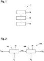
- step 10 the requirement Q D is determined in the requirement subsystem.
- step 11 the requirement Q D that was determined in step 10 is communicated to the supply side.
- step 12 the supply side operating power is determined on the basis of the demand received by the supply side from the demand subsystem.
- a controller 142 is configured to set the set point T set of a zone property, for example a desired zone temperature, e.g. B. set by a user in an office space to receive.
- the controller is also configured to receive the current value T ZONE of the zone property.
- the controller uses these two inputs to determine the control signal u ctrl .
- the control signal is used by the demand subsystem to set its operating state, where the control signal could relate to valve opening or fan speed.
- the control signal can be a normalized value from 0 to 1.
- the control signal u ctrl is communicated to the demand side processor 144 .
- the demand side processor 144 determines the demand (Q D ), e.g. B. by evaluating a demand estimator, wherein the demand estimator comprises a variable input, and wherein the variable input of the demand estimator comprises the current value T ZONE of the zone property and the control signal (u ctrl ).
- the current value of the zone property may be a measured value, for example from a temperature sensor.
- the measured value can be measured by a common sensor (such as a common temperature sensor), and both the controller 142 and the demand-side processor can use the same measured value.
- T set is a zone's temperature set point, while T ZONE is the current temperature.
- the control signal u ctrl is greater than zero and the demand side, e.g. B. FCU, with a respective power greater than zero, z. B. with a fan speed higher than zero RPM.
- GI. 1 is preferably used for an FCU, where Q D is the Q FCU , T ZONE is the zone temperature in Celsius, Q max is the peak power in watts, and u ctrl is the normalized valve opening or normalized fan speed.
- the demand estimator (e.g., Eq. 1) is a function that, given arguments including temperature and control signal, provides the demand of the demand subsystem.
- the function can be applied in step 24 in the demand subsystem processor in various forms, e.g. B. in the form of a mathematical calculation or in the form of an input-output table.
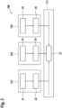
- the 3 12 is a diagram illustrating at least three demand subsystems 151, 152, 153 in communication with a supply side 111 according to various embodiments of the invention.
- the first demand subsystem 151 is to determine a first control signal u ctrl,1 in step 31, to determine (with a processor of the first demand subsystem) a corresponding first demand Q D1 in step 32 and to communicate the first demand to the Supply side 111 configured.
- the second demand subsystem 152 is configured to determine a second control signal u ctrl,2 in step 33, to determine a corresponding second demand Q D2 (with a processor of the second demand subsystem) in step 34 and to communicate the second demand to the supply side 111.
- the demand subsystem 153 is configured to determine a third control signal u ctrl,3 in step 35, to determine a corresponding third demand Q D3 (with a processor of the third demand subsystem) in step 36 and to communicate the third demand to the supply side 111.
- the HVAC system is not limited to three demand subsystems and could include a single demand subsystem as well as a plurality of demand subsystems, for example 10 or more demand subsystems.
- the invention provides for the determination of the supply side performance (in step 37) taking the demands (Q D1 ,Q D2 ,Q D3 ,...) received from the demand side and applying e.g. B.
- Evaluate the following utility function: Q s , total f Q D 1 , Q D 2 , Q D 3 , ... wherein the variable input of the utility function may include one or more demands (Q DX ) received by the respective demand subsystems from the demand side.
- At least one of the needs may be the need of an FCU (Q FCU ).
- One of the demands may be an air handling unit (Q AHU ) demand. Therefore, instead of the aggregate delayed response time on the supply side (e.g., at the chiller) given by the return liquid loop and averaging the temperature measurements on the supply side (e.g., at the chiller), the supply side of the present invention can determine its supply side performance without delay . In this way, an increase in supply-side operating power can be achieved when required with minimal Response time done, and the lowering can also be done with minimal response time. In this way, the invention provides faster response while enabling energy savings.
- the utility function (e.g., Eq. 3) is a function that, given arguments including demands (Q DX ), yields utility side operating power (Q S,total ).
- the supply function can be applied in various forms in the supply side processor, e.g. B. in the form of a mathematical calculation or in the form of an input-output table.
- Eq. 1, Eq. 2, Eq. 3 are each exemplary embodiments of the invention, but the invention is not limited thereto. Given the teachings of the present disclosure, those skilled in the art can develop various functions within the scope of the invention.
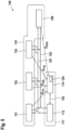
- FIG. 12 is a diagram illustrating an HVAC system including various components according to a comparative example.
- the HVAC system can be divided into a supply side 111 and a demand side 141 .
- the supply side may include a cold generator 112 (e.g., a chiller) and a building management system (BMS) 114 that may be configured to be in signal communication 103 with the cold generator 112 .
- BMS building management system
- the supply side may include one or more demand subsystems, for example, a first FCU 151, a second FCU 152, a third FCU 153, and an AHU 160.
- the HVAC system may further include a loop for moving the liquid (e.g., refrigerant, such as water), wherein the loop may include an inlet sub-loop 101 and a return sub-loop 102 .
- the chiller 112 supplies chilled liquid to the supply sub-circuit 101 to the demand side 141.
- the chiller receives the return liquid via the return sub-circuit 102, and the return liquid may be cooled at the chiller and returned to the supply sub-circuit 101.
- figure 5 shows a the diagram of figure 4 Similar diagram, but with at least one of, preferably each of the demand subsystems 151, 152, 153 and 160 comprising a demand side processor which is used to determine the respective demand Q 151 , Q 152 , Q 153 and Q 160 and to communicate the demand to the supply side, for Example for the BMS 114, is configured.
- the utility side may include a utility side processor 124 configured to determine utility demand and thus to determine utility side operational performance.
- the liquid may be part of the closed circuit, with the closest circuit having a pump for providing the liquid flow.
- the pump can be part of the supply side and it can be integrated with the chiller or separate from the chiller.
- figure 6 Figure 12 shows an example of the history of supply-side operating power, in this case cooling power, after the HVAC system is turned on.
- figure 6 12 shows an upper graph 60 and a lower graph 61. Both the upper and lower graphs show time in hours on the horizontal axis.
- the vertical axis of the upper graph 60 is cooling power (in MW) and the vertical axis of the lower graph 61 is zone temperature in Celsius.
- the top graph shows a dotted line 63 (with points represented by "X") representing a history of cooling performance versus time as measured for a comparative example.
- Solid curve 62 represents the course of simulated cooling performance versus time for the same comparative example. Measured and simulated courses are very comparable.
- the dashed line 64 represents the staging setpoint.
- the HVAC system will turn on at approximately 7.5 hours. Although the demand is available at start, the system cannot identify the immediate cooling demand from the water temperature difference. The second stage does not start until around 8 because the buffer has run out at this time and the staging set point 64 has been crossed.
- T ZONE 24 °C in figure 7
- These curves can be measured or simulated for a system.
- the demand Q D can be determined simply by knowing the control signal u ctrl and the zone temperature T ZONE .
- the invention can also be implemented with a different zone property than the zone temperature given as an example herein.
- FIG. 5 shows a graph 50 with the capacity of a refrigerator in MW on the vertical axis and time in minutes on the horizontal axis.
- Curve 51 is the measurement of the capacity of the refrigerator of a conventional system
- curve 52 is the measurement of the capacity of the refrigerator of the inventive method.
- Curve 53 is the estimated demand according to the present invention.
- the second stage with the method according to the invention achieves maximum performance very quickly compared to the comparative example. Since the chiller according to the invention receives the demand information from the demand side, it can quickly adapt the capacity of the chiller stages to the required demand, while the chiller in the comparative example reacts to the temperature of the return water, which is very slow in comparison. Thus, the example according to the invention regulates itself very quickly to a stable output and even switches off the second stage. The comparison example, on the other hand, turns off the second stage much later. In conventional systems, a further delay can be built in (e.g. in the form of hysteresis or in the form of a moving average, e.g. return water temperature) to avoid sudden changes in cooling capacity, e.g. due to water temperature spikes in the system or errors in temperature measurements. Because of this delay, the conventional HVAC system responds very slowly.
- a further delay can be built in (e.g. in the form of hysteresis or in the form of a moving average, e
- figure 10 shows the course of the zone temperature for three different zone loads.
- the vertical axis is temperature in °C
- the horizontal axis is time in minutes
- the dashed traces are the zone temperature curves of a zone cooled by a conventional method and/or system
- the solid lines are the zone temperature curves of the same by a method and/or system according to the present invention.
- figure 10 shows a reference zone in the middle, where it can be clearly seen that the cooling with the method and/or system according to the invention is much faster.
- the top graph shows the same trajectories for a zone that is less congested
- the bottom graph shows the same trajectories for a zone that is more congested.
- the arrows indicate reaching 25°C, showing that the invention is better in all three conditions, reaching a comfortable temperature of 25°C 5 to 10 minutes earlier than the prior art.
Landscapes
- Engineering & Computer Science (AREA)
- Signal Processing (AREA)
- Chemical & Material Sciences (AREA)
- Combustion & Propulsion (AREA)
- Mechanical Engineering (AREA)
- General Engineering & Computer Science (AREA)
- Physics & Mathematics (AREA)
- Fuzzy Systems (AREA)
- Mathematical Physics (AREA)
- Air Conditioning Control Device (AREA)
Claims (13)
- Procédé (1) permettant de faire fonctionner un système CVC (100), comprenant au moins un sous-système de demande (140) en communication de signal avec un côté alimentation (111), le procédé (1) comprenant les étapes consistant à :a) déterminer une demande (QD) par une fonction d'estimation de demande, la détermination étant effectuée par un processeur côté demande (144) qui est inclus dans le sous-système de demande (140) ; dans lequel la fonction d'estimation de demande comprend une entrée variable, et dans lequel l'entrée variable de la fonction d'estimation de demande comprend une propriété de zone et un signal de commande (uctrl) ;b) communiquer la demande (QD) du sous-système de demande (140) au côté alimentation (111) ; etc) déterminer une puissance de fonctionnement côté alimentation (Qs,total) en fonction de la demande (QD) et de paramètres côté alimentation ; dans lequel la détermination est effectuée par un processeur côté alimentation (124) qui est inclus dans le côté alimentation (111).
- Procédé (1) selon la revendication 1, dans lequel le sous-système de demande (140) est un climatiseur, le climatiseur étant de préférence un ventilo-convecteur (151, 152, 153) ou une unité de traitement de l'air (160) .
- Procédé (1) selon l'une quelconque des revendications 1 ou 2, dans lequel la propriété de zone correspond à une température de zone (TZONE).
- Procédé (1) selon l'une quelconque des revendications précédentes, dans lequel la propriété de zone correspond à une humidité de l'air.
- Procédé (1) selon l'une quelconque des revendications précédentes, dans lequel le signal de commande (uctrl) correspond à une vitesse de rotation de ventilateur.
- Procédé (1) selon l'une quelconque des revendications précédentes, dans lequel le signal de commande (uctrl) correspond à une ouverture de vanne.
- Procédé (1) selon l'une quelconque des revendications précédentes permettant de faire fonctionner le système CVC (100), dans lequel le système CVC (100) comprend en outre un générateur de froid (112) du côté alimentation (111), le procédé (1) comprenant en outre :
la détermination d'une puissance de fonctionnement du générateur de froid, la puissance de fonctionnement du générateur de froid étant fonction au moins de la température d'arrivée du liquide (Tsup), de la température de retour du liquide, du débit du liquide (m) et de la demande (QD). - Procédé (1) selon l'une quelconque des revendications précédentes, dans lequel la fonction d'estimation de demande est indépendante au moins : des dimensions de zone, du volume de zone, de la surface de zone, de la capacité thermique de zone ou d'une combinaison de ceux-ci.
- Procédé (1) selon l'une quelconque des revendications précédentes, comprenant en outre les étapes consistant à :ajouter au moins un sous-système de demande supplémentaire (152, 153) au système CVC (100), etétablir la communication de signal entre le sous-système de demande supplémentaire (152, 153) et le côté alimentation (111) de sorte que le sous-système de demande supplémentaire (152, 153) est en mesure d'exécuter l'étape suivante consistant à :
communiquer la demande (Q152, Q153) du sous-système de demande supplémentaire (152, 153) au côté alimentation (111). - Procédé (1) selon l'une quelconque des revendications précédentes, dans lequel le côté alimentation (111) présente un temps de réponse, et le côté alimentation (111) est configuré pour fonctionner dans :un premier mode, dans lequel au moins soit la demande (QD), soit une demande supplémentaire (Q152, Q153) est reçue ; etun deuxième mode, dans lequel aucune demande (QD) n'est reçue ;dans lequel le côté alimentation (111) est configuré pour augmenter le temps de réponse lorsqu'il fonctionne dans le premier mode et reconnaît un deuxième mode, et pour diminuer le temps de réponse lorsqu'il fonctionne dans le deuxième mode et reconnaît un premier mode.
- Sous-système de demande pour un système CVC (100), configuré pour communiquer de manière opérationnelle avec un côté alimentation (111), le côté alimentation (111) comprenant :un récepteur côté alimentation pour recevoir une demande (QD) du sous-système de demande (140) ; etun processeur côté alimentation (124) qui est configuré pour être en mesure de déterminer une puissance de fonctionnement côté alimentation (Qs,total) en fonction de la demande (QD) ;le sous-système de demande comprenant :un contrôleur (142) pour fournir un signal de commandes (uctrl) ;un processeur côté demande (144) qui est configuré pour déterminer une demande (QD) par une fonction d'estimation de demande, la fonction d'estimation de demande comprenant une entrée variable, et dans lequel l'entrée variable de la fonction d'estimation de demande comprend une propriété de zone et le signal de commande (uctrl) ;un émetteur côté demande pour envoyer la demande (QD) au côté alimentation (111).
- Système CVC (100), comprenant :
un côté alimentation (111) qui est configuré pour communiquer de manière opérationnelle avec au moins un sous-système de demande (140) selon la revendication 11, le côté alimentation (111) comprenant :un récepteur côté alimentation pour recevoir la demande (QD) du sous-système de demande (140) ; etun processeur côté alimentation (124) qui est configuré pour déterminer une puissance de fonctionnement côté alimentation (Qs,total) en fonction de la demande (QD). - Système CVC (100) selon la revendication 12, comprenant en outre au moins un sous-système de demande (140) selon la revendication 11, et de préférence dans lequel le sous-système de demande (140) est sélectionné parmi au moins un élément : d'un ventilo-convecteur (151, 152, 153) et d'une unité de traitement de l'air (160) .
Applications Claiming Priority (1)
| Application Number | Priority Date | Filing Date | Title |
|---|---|---|---|
| DE102018205415.0A DE102018205415A1 (de) | 2018-04-11 | 2018-04-11 | Hvac-system und verfahren zum betreiben eines hvac-systems |
Publications (2)
| Publication Number | Publication Date |
|---|---|
| EP3553403A1 EP3553403A1 (fr) | 2019-10-16 |
| EP3553403B1 true EP3553403B1 (fr) | 2023-08-23 |
Family
ID=66102960
Family Applications (1)
| Application Number | Title | Priority Date | Filing Date |
|---|---|---|---|
| EP19168141.0A Active EP3553403B1 (fr) | 2018-04-11 | 2019-04-09 | Système cvc et procédé de fonctionnement d'un système cvc |
Country Status (2)
| Country | Link |
|---|---|
| EP (1) | EP3553403B1 (fr) |
| DE (1) | DE102018205415A1 (fr) |
Family Cites Families (4)
| Publication number | Priority date | Publication date | Assignee | Title |
|---|---|---|---|---|
| KR100766177B1 (ko) * | 2006-08-04 | 2007-10-10 | 주식회사 대우일렉트로닉스 | 공기 조화기의 운전 제어 방법 |
| JP6324707B2 (ja) * | 2013-11-13 | 2018-05-16 | 三菱重工サーマルシステムズ株式会社 | 熱源機及びその制御方法 |
| US11105529B2 (en) * | 2014-05-15 | 2021-08-31 | Carrier Corporation | Multi-zone indoor climate control and a method of using the same |
| SG11201706843RA (en) * | 2015-03-17 | 2017-09-28 | Univ Nanyang Tech | Method of operating a building environment management system |
-
2018
- 2018-04-11 DE DE102018205415.0A patent/DE102018205415A1/de not_active Withdrawn
-
2019
- 2019-04-09 EP EP19168141.0A patent/EP3553403B1/fr active Active
Also Published As
| Publication number | Publication date |
|---|---|
| EP3553403A1 (fr) | 2019-10-16 |
| DE102018205415A1 (de) | 2019-10-17 |
Similar Documents
| Publication | Publication Date | Title |
|---|---|---|
| DE112016000966B4 (de) | Verfahren zum Steuern einer HVAC-Einheit auf Grundlage von Thermostatsignalen sowie nichttransitorisches computerlesbares Medium | |
| EP0935181B1 (fr) | Procédé et dispositif de régulation par auto-apprentissage pour un système de chauffage | |
| DE10057219C2 (de) | Klimaanlage für mehrere Räume | |
| DE69311762T2 (de) | Klimagerät | |
| EP2863134B1 (fr) | Procédé d'adaptation d'une courbe de chauffe | |
| EP2960587A1 (fr) | Procédé de limitation du débit d'alimentation dans un système de transmission de chaleur | |
| DE102013114374B4 (de) | Verfahren zur Drehzahlregelung bei einem Verdichter mit variabler Drehzahl | |
| EP2667278B1 (fr) | Procédé et dispositif de commande des paramètres d'air dans des pièces | |
| EP3438567A1 (fr) | Capteur logiciel destiné à l'identification et au réglage ou à la commande d'un système de pompe à chaleur | |
| DE102022001630A1 (de) | Verfahren zur Steuerung und/oder Regelung einer Heizungsanlage zum Beheizen wenigstens eines Raumes sowie Heizungsanlage | |
| EP3101352A1 (fr) | Procede de fonctionnement d'une installation de chauffage et dispositif de regulation comprenant un capteur de difference de pression | |
| EP2894417B1 (fr) | Système de pompe à chaleur | |
| EP3553403B1 (fr) | Système cvc et procédé de fonctionnement d'un système cvc | |
| EP2375174A2 (fr) | Installation de pompe à chaleur et procédé destiné au réglage d'une installation de pompe à chaleur | |
| WO2020165037A1 (fr) | Procédé pour réguler une pompe de circulation | |
| DE10052898A1 (de) | Fahrzeugklimaanlage | |
| EP2896900B1 (fr) | Procédé de contrôle d'une puissance de refroidissement ou de chauffage pour un système de chauffage / refroidissement avec plusieurs sources et unité de contrôle pour executer le procédé | |
| DE202014010802U1 (de) | Wärmepumpenvorrichtung | |
| EP0192227A2 (fr) | Procédé de régulation de température de locaux | |
| EP3997389B1 (fr) | Procédé de commande d'un ensemble composé d'une pompe de chauffage et d'une vanne mélangeuse à trois voies | |
| EP2905671A2 (fr) | Procédé de synchronisation d'une installation thermique avec un système thermique | |
| EP4462031A1 (fr) | Procédé de fonctionnement d'une installation de chauffage, programme informatique, appareil de régulation et de commande et installation de chauffage | |
| EP4491951A1 (fr) | Procédé de réglage d'une soupape de dérivation d'un circuit de chauffage d'un système de climatisation, système de climatisation et programme informatique | |
| DE102013014832A1 (de) | Wärmepumpenvorrichtung | |
| WO2023217752A1 (fr) | Procédé de surveillance et/ou de commande d'un système de chauffage |
Legal Events
| Date | Code | Title | Description |
|---|---|---|---|
| PUAI | Public reference made under article 153(3) epc to a published international application that has entered the european phase |
Free format text: ORIGINAL CODE: 0009012 |
|
| STAA | Information on the status of an ep patent application or granted ep patent |
Free format text: STATUS: THE APPLICATION HAS BEEN PUBLISHED |
|
| AK | Designated contracting states |
Kind code of ref document: A1 Designated state(s): AL AT BE BG CH CY CZ DE DK EE ES FI FR GB GR HR HU IE IS IT LI LT LU LV MC MK MT NL NO PL PT RO RS SE SI SK SM TR |
|
| AX | Request for extension of the european patent |
Extension state: BA ME |
|
| RIN1 | Information on inventor provided before grant (corrected) |
Inventor name: PRADIPTA, JUSTIN |
|
| STAA | Information on the status of an ep patent application or granted ep patent |
Free format text: STATUS: REQUEST FOR EXAMINATION WAS MADE |
|
| RAP1 | Party data changed (applicant data changed or rights of an application transferred) |
Owner name: ROBERT BOSCH GMBH |
|
| 17P | Request for examination filed |
Effective date: 20200416 |
|
| RBV | Designated contracting states (corrected) |
Designated state(s): AL AT BE BG CH CY CZ DE DK EE ES FI FR GB GR HR HU IE IS IT LI LT LU LV MC MK MT NL NO PL PT RO RS SE SI SK SM TR |
|
| STAA | Information on the status of an ep patent application or granted ep patent |
Free format text: STATUS: EXAMINATION IS IN PROGRESS |
|
| 17Q | First examination report despatched |
Effective date: 20220908 |
|
| GRAP | Despatch of communication of intention to grant a patent |
Free format text: ORIGINAL CODE: EPIDOSNIGR1 |
|
| STAA | Information on the status of an ep patent application or granted ep patent |
Free format text: STATUS: GRANT OF PATENT IS INTENDED |
|
| INTG | Intention to grant announced |
Effective date: 20230328 |
|
| GRAS | Grant fee paid |
Free format text: ORIGINAL CODE: EPIDOSNIGR3 |
|
| GRAA | (expected) grant |
Free format text: ORIGINAL CODE: 0009210 |
|
| STAA | Information on the status of an ep patent application or granted ep patent |
Free format text: STATUS: THE PATENT HAS BEEN GRANTED |
|
| AK | Designated contracting states |
Kind code of ref document: B1 Designated state(s): AL AT BE BG CH CY CZ DE DK EE ES FI FR GB GR HR HU IE IS IT LI LT LU LV MC MK MT NL NO PL PT RO RS SE SI SK SM TR |
|
| REG | Reference to a national code |
Ref country code: GB Ref legal event code: FG4D Free format text: NOT ENGLISH |
|
| REG | Reference to a national code |
Ref country code: CH Ref legal event code: EP |
|
| REG | Reference to a national code |
Ref country code: DE Ref legal event code: R096 Ref document number: 502019009009 Country of ref document: DE |
|
| REG | Reference to a national code |
Ref country code: IE Ref legal event code: FG4D Free format text: LANGUAGE OF EP DOCUMENT: GERMAN |
|
| REG | Reference to a national code |
Ref country code: LT Ref legal event code: MG9D |
|
| REG | Reference to a national code |
Ref country code: NL Ref legal event code: MP Effective date: 20230823 |
|
| PG25 | Lapsed in a contracting state [announced via postgrant information from national office to epo] |
Ref country code: GR Free format text: LAPSE BECAUSE OF FAILURE TO SUBMIT A TRANSLATION OF THE DESCRIPTION OR TO PAY THE FEE WITHIN THE PRESCRIBED TIME-LIMIT Effective date: 20231124 |
|
| PG25 | Lapsed in a contracting state [announced via postgrant information from national office to epo] |
Ref country code: IS Free format text: LAPSE BECAUSE OF FAILURE TO SUBMIT A TRANSLATION OF THE DESCRIPTION OR TO PAY THE FEE WITHIN THE PRESCRIBED TIME-LIMIT Effective date: 20231223 |
|
| PG25 | Lapsed in a contracting state [announced via postgrant information from national office to epo] |
Ref country code: SE Free format text: LAPSE BECAUSE OF FAILURE TO SUBMIT A TRANSLATION OF THE DESCRIPTION OR TO PAY THE FEE WITHIN THE PRESCRIBED TIME-LIMIT Effective date: 20230823 Ref country code: RS Free format text: LAPSE BECAUSE OF FAILURE TO SUBMIT A TRANSLATION OF THE DESCRIPTION OR TO PAY THE FEE WITHIN THE PRESCRIBED TIME-LIMIT Effective date: 20230823 Ref country code: PT Free format text: LAPSE BECAUSE OF FAILURE TO SUBMIT A TRANSLATION OF THE DESCRIPTION OR TO PAY THE FEE WITHIN THE PRESCRIBED TIME-LIMIT Effective date: 20231226 Ref country code: NO Free format text: LAPSE BECAUSE OF FAILURE TO SUBMIT A TRANSLATION OF THE DESCRIPTION OR TO PAY THE FEE WITHIN THE PRESCRIBED TIME-LIMIT Effective date: 20231123 Ref country code: NL Free format text: LAPSE BECAUSE OF FAILURE TO SUBMIT A TRANSLATION OF THE DESCRIPTION OR TO PAY THE FEE WITHIN THE PRESCRIBED TIME-LIMIT Effective date: 20230823 Ref country code: LV Free format text: LAPSE BECAUSE OF FAILURE TO SUBMIT A TRANSLATION OF THE DESCRIPTION OR TO PAY THE FEE WITHIN THE PRESCRIBED TIME-LIMIT Effective date: 20230823 Ref country code: LT Free format text: LAPSE BECAUSE OF FAILURE TO SUBMIT A TRANSLATION OF THE DESCRIPTION OR TO PAY THE FEE WITHIN THE PRESCRIBED TIME-LIMIT Effective date: 20230823 Ref country code: IS Free format text: LAPSE BECAUSE OF FAILURE TO SUBMIT A TRANSLATION OF THE DESCRIPTION OR TO PAY THE FEE WITHIN THE PRESCRIBED TIME-LIMIT Effective date: 20231223 Ref country code: HR Free format text: LAPSE BECAUSE OF FAILURE TO SUBMIT A TRANSLATION OF THE DESCRIPTION OR TO PAY THE FEE WITHIN THE PRESCRIBED TIME-LIMIT Effective date: 20230823 Ref country code: GR Free format text: LAPSE BECAUSE OF FAILURE TO SUBMIT A TRANSLATION OF THE DESCRIPTION OR TO PAY THE FEE WITHIN THE PRESCRIBED TIME-LIMIT Effective date: 20231124 Ref country code: FI Free format text: LAPSE BECAUSE OF FAILURE TO SUBMIT A TRANSLATION OF THE DESCRIPTION OR TO PAY THE FEE WITHIN THE PRESCRIBED TIME-LIMIT Effective date: 20230823 |
|
| PG25 | Lapsed in a contracting state [announced via postgrant information from national office to epo] |
Ref country code: PL Free format text: LAPSE BECAUSE OF FAILURE TO SUBMIT A TRANSLATION OF THE DESCRIPTION OR TO PAY THE FEE WITHIN THE PRESCRIBED TIME-LIMIT Effective date: 20230823 |
|
| PG25 | Lapsed in a contracting state [announced via postgrant information from national office to epo] |
Ref country code: ES Free format text: LAPSE BECAUSE OF FAILURE TO SUBMIT A TRANSLATION OF THE DESCRIPTION OR TO PAY THE FEE WITHIN THE PRESCRIBED TIME-LIMIT Effective date: 20230823 |
|
| PG25 | Lapsed in a contracting state [announced via postgrant information from national office to epo] |
Ref country code: SM Free format text: LAPSE BECAUSE OF FAILURE TO SUBMIT A TRANSLATION OF THE DESCRIPTION OR TO PAY THE FEE WITHIN THE PRESCRIBED TIME-LIMIT Effective date: 20230823 Ref country code: RO Free format text: LAPSE BECAUSE OF FAILURE TO SUBMIT A TRANSLATION OF THE DESCRIPTION OR TO PAY THE FEE WITHIN THE PRESCRIBED TIME-LIMIT Effective date: 20230823 Ref country code: ES Free format text: LAPSE BECAUSE OF FAILURE TO SUBMIT A TRANSLATION OF THE DESCRIPTION OR TO PAY THE FEE WITHIN THE PRESCRIBED TIME-LIMIT Effective date: 20230823 Ref country code: EE Free format text: LAPSE BECAUSE OF FAILURE TO SUBMIT A TRANSLATION OF THE DESCRIPTION OR TO PAY THE FEE WITHIN THE PRESCRIBED TIME-LIMIT Effective date: 20230823 Ref country code: DK Free format text: LAPSE BECAUSE OF FAILURE TO SUBMIT A TRANSLATION OF THE DESCRIPTION OR TO PAY THE FEE WITHIN THE PRESCRIBED TIME-LIMIT Effective date: 20230823 Ref country code: CZ Free format text: LAPSE BECAUSE OF FAILURE TO SUBMIT A TRANSLATION OF THE DESCRIPTION OR TO PAY THE FEE WITHIN THE PRESCRIBED TIME-LIMIT Effective date: 20230823 Ref country code: SK Free format text: LAPSE BECAUSE OF FAILURE TO SUBMIT A TRANSLATION OF THE DESCRIPTION OR TO PAY THE FEE WITHIN THE PRESCRIBED TIME-LIMIT Effective date: 20230823 |
|
| REG | Reference to a national code |
Ref country code: DE Ref legal event code: R097 Ref document number: 502019009009 Country of ref document: DE |
|
| PLBE | No opposition filed within time limit |
Free format text: ORIGINAL CODE: 0009261 |
|
| STAA | Information on the status of an ep patent application or granted ep patent |
Free format text: STATUS: NO OPPOSITION FILED WITHIN TIME LIMIT |
|
| 26N | No opposition filed |
Effective date: 20240524 |
|
| PG25 | Lapsed in a contracting state [announced via postgrant information from national office to epo] |
Ref country code: SI Free format text: LAPSE BECAUSE OF FAILURE TO SUBMIT A TRANSLATION OF THE DESCRIPTION OR TO PAY THE FEE WITHIN THE PRESCRIBED TIME-LIMIT Effective date: 20230823 |
|
| PG25 | Lapsed in a contracting state [announced via postgrant information from national office to epo] |
Ref country code: BG Free format text: LAPSE BECAUSE OF FAILURE TO SUBMIT A TRANSLATION OF THE DESCRIPTION OR TO PAY THE FEE WITHIN THE PRESCRIBED TIME-LIMIT Effective date: 20230823 |
|
| PG25 | Lapsed in a contracting state [announced via postgrant information from national office to epo] |
Ref country code: MC Free format text: LAPSE BECAUSE OF FAILURE TO SUBMIT A TRANSLATION OF THE DESCRIPTION OR TO PAY THE FEE WITHIN THE PRESCRIBED TIME-LIMIT Effective date: 20230823 |
|
| PG25 | Lapsed in a contracting state [announced via postgrant information from national office to epo] |
Ref country code: MC Free format text: LAPSE BECAUSE OF FAILURE TO SUBMIT A TRANSLATION OF THE DESCRIPTION OR TO PAY THE FEE WITHIN THE PRESCRIBED TIME-LIMIT Effective date: 20230823 Ref country code: BG Free format text: LAPSE BECAUSE OF FAILURE TO SUBMIT A TRANSLATION OF THE DESCRIPTION OR TO PAY THE FEE WITHIN THE PRESCRIBED TIME-LIMIT Effective date: 20230823 |
|
| REG | Reference to a national code |
Ref country code: CH Ref legal event code: PL |
|
| PG25 | Lapsed in a contracting state [announced via postgrant information from national office to epo] |
Ref country code: LU Free format text: LAPSE BECAUSE OF NON-PAYMENT OF DUE FEES Effective date: 20240409 |
|
| GBPC | Gb: european patent ceased through non-payment of renewal fee |
Effective date: 20240409 |
|
| REG | Reference to a national code |
Ref country code: BE Ref legal event code: MM Effective date: 20240430 |
|
| PG25 | Lapsed in a contracting state [announced via postgrant information from national office to epo] |
Ref country code: LU Free format text: LAPSE BECAUSE OF NON-PAYMENT OF DUE FEES Effective date: 20240409 |
|
| PG25 | Lapsed in a contracting state [announced via postgrant information from national office to epo] |
Ref country code: BE Free format text: LAPSE BECAUSE OF NON-PAYMENT OF DUE FEES Effective date: 20240430 |
|
| PG25 | Lapsed in a contracting state [announced via postgrant information from national office to epo] |
Ref country code: GB Free format text: LAPSE BECAUSE OF NON-PAYMENT OF DUE FEES Effective date: 20240409 |
|
| PG25 | Lapsed in a contracting state [announced via postgrant information from national office to epo] |
Ref country code: FR Free format text: LAPSE BECAUSE OF NON-PAYMENT OF DUE FEES Effective date: 20240430 |
|
| PG25 | Lapsed in a contracting state [announced via postgrant information from national office to epo] |
Ref country code: GB Free format text: LAPSE BECAUSE OF NON-PAYMENT OF DUE FEES Effective date: 20240409 Ref country code: FR Free format text: LAPSE BECAUSE OF NON-PAYMENT OF DUE FEES Effective date: 20240430 Ref country code: BE Free format text: LAPSE BECAUSE OF NON-PAYMENT OF DUE FEES Effective date: 20240430 Ref country code: CH Free format text: LAPSE BECAUSE OF NON-PAYMENT OF DUE FEES Effective date: 20240430 |
|
| PG25 | Lapsed in a contracting state [announced via postgrant information from national office to epo] |
Ref country code: IE Free format text: LAPSE BECAUSE OF NON-PAYMENT OF DUE FEES Effective date: 20240409 |
|
| REG | Reference to a national code |
Ref country code: AT Ref legal event code: MM01 Ref document number: 1603015 Country of ref document: AT Kind code of ref document: T Effective date: 20240409 |
|
| PGFP | Annual fee paid to national office [announced via postgrant information from national office to epo] |
Ref country code: DE Payment date: 20250624 Year of fee payment: 7 |
|
| PGFP | Annual fee paid to national office [announced via postgrant information from national office to epo] |
Ref country code: IT Payment date: 20250430 Year of fee payment: 7 |
|
| PG25 | Lapsed in a contracting state [announced via postgrant information from national office to epo] |
Ref country code: AT Free format text: LAPSE BECAUSE OF NON-PAYMENT OF DUE FEES Effective date: 20240409 |
|
| PG25 | Lapsed in a contracting state [announced via postgrant information from national office to epo] |
Ref country code: CY Free format text: LAPSE BECAUSE OF FAILURE TO SUBMIT A TRANSLATION OF THE DESCRIPTION OR TO PAY THE FEE WITHIN THE PRESCRIBED TIME-LIMIT; INVALID AB INITIO Effective date: 20190409 |
|
| PG25 | Lapsed in a contracting state [announced via postgrant information from national office to epo] |
Ref country code: HU Free format text: LAPSE BECAUSE OF FAILURE TO SUBMIT A TRANSLATION OF THE DESCRIPTION OR TO PAY THE FEE WITHIN THE PRESCRIBED TIME-LIMIT; INVALID AB INITIO Effective date: 20190409 |