EP3553424A1 - Vorrichtung und verfahren zur detektion von kältemittelleckagen eines luftquellenkühlsystems - Google Patents
Vorrichtung und verfahren zur detektion von kältemittelleckagen eines luftquellenkühlsystems Download PDFInfo
- Publication number
- EP3553424A1 EP3553424A1 EP19167627.9A EP19167627A EP3553424A1 EP 3553424 A1 EP3553424 A1 EP 3553424A1 EP 19167627 A EP19167627 A EP 19167627A EP 3553424 A1 EP3553424 A1 EP 3553424A1
- Authority
- EP
- European Patent Office
- Prior art keywords
- predefined
- air source
- cumulative score
- less
- source cooling
- Prior art date
- Legal status (The legal status is an assumption and is not a legal conclusion. Google has not performed a legal analysis and makes no representation as to the accuracy of the status listed.)
- Pending
Links
- 238000001816 cooling Methods 0.000 title claims abstract description 97
- 239000003507 refrigerant Substances 0.000 title claims abstract description 68
- 238000000034 method Methods 0.000 title claims abstract description 38
- 238000001514 detection method Methods 0.000 title abstract description 6
- 230000001186 cumulative effect Effects 0.000 claims abstract description 93
- 238000004781 supercooling Methods 0.000 claims description 74
- XLYOFNOQVPJJNP-UHFFFAOYSA-N water Substances O XLYOFNOQVPJJNP-UHFFFAOYSA-N 0.000 claims description 39
- 238000010586 diagram Methods 0.000 claims description 8
- 230000005236 sound signal Effects 0.000 description 2
- 238000003915 air pollution Methods 0.000 description 1
- 230000000712 assembly Effects 0.000 description 1
- 238000000429 assembly Methods 0.000 description 1
- 238000010276 construction Methods 0.000 description 1
- 239000000463 material Substances 0.000 description 1
- 239000000203 mixture Substances 0.000 description 1
- 238000012544 monitoring process Methods 0.000 description 1
- 238000005057 refrigeration Methods 0.000 description 1
Images


Classifications
-
- F—MECHANICAL ENGINEERING; LIGHTING; HEATING; WEAPONS; BLASTING
- F25—REFRIGERATION OR COOLING; COMBINED HEATING AND REFRIGERATION SYSTEMS; HEAT PUMP SYSTEMS; MANUFACTURE OR STORAGE OF ICE; LIQUEFACTION SOLIDIFICATION OF GASES
- F25B—REFRIGERATION MACHINES, PLANTS OR SYSTEMS; COMBINED HEATING AND REFRIGERATION SYSTEMS; HEAT PUMP SYSTEMS
- F25B30/00—Heat pumps
-
- F—MECHANICAL ENGINEERING; LIGHTING; HEATING; WEAPONS; BLASTING
- F25—REFRIGERATION OR COOLING; COMBINED HEATING AND REFRIGERATION SYSTEMS; HEAT PUMP SYSTEMS; MANUFACTURE OR STORAGE OF ICE; LIQUEFACTION SOLIDIFICATION OF GASES
- F25B—REFRIGERATION MACHINES, PLANTS OR SYSTEMS; COMBINED HEATING AND REFRIGERATION SYSTEMS; HEAT PUMP SYSTEMS
- F25B45/00—Arrangements for charging or discharging refrigerant
-
- F—MECHANICAL ENGINEERING; LIGHTING; HEATING; WEAPONS; BLASTING
- F25—REFRIGERATION OR COOLING; COMBINED HEATING AND REFRIGERATION SYSTEMS; HEAT PUMP SYSTEMS; MANUFACTURE OR STORAGE OF ICE; LIQUEFACTION SOLIDIFICATION OF GASES
- F25B—REFRIGERATION MACHINES, PLANTS OR SYSTEMS; COMBINED HEATING AND REFRIGERATION SYSTEMS; HEAT PUMP SYSTEMS
- F25B49/00—Arrangement or mounting of control or safety devices
- F25B49/005—Arrangement or mounting of control or safety devices of safety devices
-
- F—MECHANICAL ENGINEERING; LIGHTING; HEATING; WEAPONS; BLASTING
- F25—REFRIGERATION OR COOLING; COMBINED HEATING AND REFRIGERATION SYSTEMS; HEAT PUMP SYSTEMS; MANUFACTURE OR STORAGE OF ICE; LIQUEFACTION SOLIDIFICATION OF GASES
- F25B—REFRIGERATION MACHINES, PLANTS OR SYSTEMS; COMBINED HEATING AND REFRIGERATION SYSTEMS; HEAT PUMP SYSTEMS
- F25B49/00—Arrangement or mounting of control or safety devices
- F25B49/02—Arrangement or mounting of control or safety devices for compression type machines, plants or systems
-
- F—MECHANICAL ENGINEERING; LIGHTING; HEATING; WEAPONS; BLASTING
- F25—REFRIGERATION OR COOLING; COMBINED HEATING AND REFRIGERATION SYSTEMS; HEAT PUMP SYSTEMS; MANUFACTURE OR STORAGE OF ICE; LIQUEFACTION SOLIDIFICATION OF GASES
- F25B—REFRIGERATION MACHINES, PLANTS OR SYSTEMS; COMBINED HEATING AND REFRIGERATION SYSTEMS; HEAT PUMP SYSTEMS
- F25B2339/00—Details of evaporators; Details of condensers
- F25B2339/04—Details of condensers
- F25B2339/047—Water-cooled condensers
-
- F—MECHANICAL ENGINEERING; LIGHTING; HEATING; WEAPONS; BLASTING
- F25—REFRIGERATION OR COOLING; COMBINED HEATING AND REFRIGERATION SYSTEMS; HEAT PUMP SYSTEMS; MANUFACTURE OR STORAGE OF ICE; LIQUEFACTION SOLIDIFICATION OF GASES
- F25B—REFRIGERATION MACHINES, PLANTS OR SYSTEMS; COMBINED HEATING AND REFRIGERATION SYSTEMS; HEAT PUMP SYSTEMS
- F25B2345/00—Details for charging or discharging refrigerants; Service stations therefor
- F25B2345/003—Control issues for charging or collecting refrigerant to or from a cycle
-
- F—MECHANICAL ENGINEERING; LIGHTING; HEATING; WEAPONS; BLASTING
- F25—REFRIGERATION OR COOLING; COMBINED HEATING AND REFRIGERATION SYSTEMS; HEAT PUMP SYSTEMS; MANUFACTURE OR STORAGE OF ICE; LIQUEFACTION SOLIDIFICATION OF GASES
- F25B—REFRIGERATION MACHINES, PLANTS OR SYSTEMS; COMBINED HEATING AND REFRIGERATION SYSTEMS; HEAT PUMP SYSTEMS
- F25B2500/00—Problems to be solved
- F25B2500/22—Preventing, detecting or repairing leaks of refrigeration fluids
- F25B2500/221—Preventing leaks from developing
-
- F—MECHANICAL ENGINEERING; LIGHTING; HEATING; WEAPONS; BLASTING
- F25—REFRIGERATION OR COOLING; COMBINED HEATING AND REFRIGERATION SYSTEMS; HEAT PUMP SYSTEMS; MANUFACTURE OR STORAGE OF ICE; LIQUEFACTION SOLIDIFICATION OF GASES
- F25B—REFRIGERATION MACHINES, PLANTS OR SYSTEMS; COMBINED HEATING AND REFRIGERATION SYSTEMS; HEAT PUMP SYSTEMS
- F25B2500/00—Problems to be solved
- F25B2500/22—Preventing, detecting or repairing leaks of refrigeration fluids
- F25B2500/222—Detecting refrigerant leaks
-
- F—MECHANICAL ENGINEERING; LIGHTING; HEATING; WEAPONS; BLASTING
- F25—REFRIGERATION OR COOLING; COMBINED HEATING AND REFRIGERATION SYSTEMS; HEAT PUMP SYSTEMS; MANUFACTURE OR STORAGE OF ICE; LIQUEFACTION SOLIDIFICATION OF GASES
- F25B—REFRIGERATION MACHINES, PLANTS OR SYSTEMS; COMBINED HEATING AND REFRIGERATION SYSTEMS; HEAT PUMP SYSTEMS
- F25B2600/00—Control issues
- F25B2600/25—Control of valves
- F25B2600/2513—Expansion valves
-
- F—MECHANICAL ENGINEERING; LIGHTING; HEATING; WEAPONS; BLASTING
- F25—REFRIGERATION OR COOLING; COMBINED HEATING AND REFRIGERATION SYSTEMS; HEAT PUMP SYSTEMS; MANUFACTURE OR STORAGE OF ICE; LIQUEFACTION SOLIDIFICATION OF GASES
- F25B—REFRIGERATION MACHINES, PLANTS OR SYSTEMS; COMBINED HEATING AND REFRIGERATION SYSTEMS; HEAT PUMP SYSTEMS
- F25B2700/00—Sensing or detecting of parameters; Sensors therefor
- F25B2700/17—Speeds
- F25B2700/171—Speeds of the compressor
-
- F—MECHANICAL ENGINEERING; LIGHTING; HEATING; WEAPONS; BLASTING
- F25—REFRIGERATION OR COOLING; COMBINED HEATING AND REFRIGERATION SYSTEMS; HEAT PUMP SYSTEMS; MANUFACTURE OR STORAGE OF ICE; LIQUEFACTION SOLIDIFICATION OF GASES
- F25B—REFRIGERATION MACHINES, PLANTS OR SYSTEMS; COMBINED HEATING AND REFRIGERATION SYSTEMS; HEAT PUMP SYSTEMS
- F25B2700/00—Sensing or detecting of parameters; Sensors therefor
- F25B2700/19—Pressures
- F25B2700/193—Pressures of the compressor
- F25B2700/1931—Discharge pressures
-
- F—MECHANICAL ENGINEERING; LIGHTING; HEATING; WEAPONS; BLASTING
- F25—REFRIGERATION OR COOLING; COMBINED HEATING AND REFRIGERATION SYSTEMS; HEAT PUMP SYSTEMS; MANUFACTURE OR STORAGE OF ICE; LIQUEFACTION SOLIDIFICATION OF GASES
- F25B—REFRIGERATION MACHINES, PLANTS OR SYSTEMS; COMBINED HEATING AND REFRIGERATION SYSTEMS; HEAT PUMP SYSTEMS
- F25B2700/00—Sensing or detecting of parameters; Sensors therefor
- F25B2700/21—Temperatures
- F25B2700/2115—Temperatures of a compressor or the drive means therefor
- F25B2700/21152—Temperatures of a compressor or the drive means therefor at the discharge side of the compressor
-
- F—MECHANICAL ENGINEERING; LIGHTING; HEATING; WEAPONS; BLASTING
- F25—REFRIGERATION OR COOLING; COMBINED HEATING AND REFRIGERATION SYSTEMS; HEAT PUMP SYSTEMS; MANUFACTURE OR STORAGE OF ICE; LIQUEFACTION SOLIDIFICATION OF GASES
- F25B—REFRIGERATION MACHINES, PLANTS OR SYSTEMS; COMBINED HEATING AND REFRIGERATION SYSTEMS; HEAT PUMP SYSTEMS
- F25B2700/00—Sensing or detecting of parameters; Sensors therefor
- F25B2700/21—Temperatures
- F25B2700/2116—Temperatures of a condenser
- F25B2700/21163—Temperatures of a condenser of the refrigerant at the outlet of the condenser
-
- F—MECHANICAL ENGINEERING; LIGHTING; HEATING; WEAPONS; BLASTING
- F25—REFRIGERATION OR COOLING; COMBINED HEATING AND REFRIGERATION SYSTEMS; HEAT PUMP SYSTEMS; MANUFACTURE OR STORAGE OF ICE; LIQUEFACTION SOLIDIFICATION OF GASES
- F25B—REFRIGERATION MACHINES, PLANTS OR SYSTEMS; COMBINED HEATING AND REFRIGERATION SYSTEMS; HEAT PUMP SYSTEMS
- F25B2700/00—Sensing or detecting of parameters; Sensors therefor
- F25B2700/21—Temperatures
- F25B2700/2117—Temperatures of an evaporator
- F25B2700/21175—Temperatures of an evaporator of the refrigerant at the outlet of the evaporator
Definitions
- the present invention relates to a method and a device for detecting a refrigerant leakage of an air source cooling-only system, which is used for monitoring whether a leakage has occurred in a cooling system.
- an air source cooling-only system generally uses a refrigerant to perform a refrigeration cycle operation.
- the refrigerant may leak from pipelines for a variety of reasons.
- a cooling-only module may probably shut down due to a leakage, thereby resulting in economic losses, air pollution, and repair costs.
- the existing air source cooling-only system is not capable of automatically detecting a refrigerant leakage.
- a special-purpose apparatus can be used to detect whether a leakage has occurred, such detection is time-consuming and expensive.
- the present invention provides a device for detecting a refrigerant leakage of an air source cooling-only system comprising:
- the data comparison module comprises a compressor speed or capacity comparison module; the compressor speed or capacity comparison module is configured to compare the compressor speed or capacity with a minimum speed or capacity when the air source cooling-only system has been continuously operated for a first predefined period of time and an absolute value of a temperature difference between inlet and outlet water is less than a first predefined value; and the cumulative score updating module is configured to increase the cumulative score by a first score when the compressor speed or capacity is greater than or equal to the minimum speed or capacity.
- the data comparison module comprises a superheat comparison module; the superheat comparison module is configured to compare a superheat degree with a sum of a superheat degree setting value and a third predefined value when the air source cooling-only system has been continuously operated for the first predefined period of time, the absolute value of the temperature difference between inlet and outlet water is not less than the first predefined value, a supercooling degree is less than a second predefined value, and an expansion valve opening degree is equal to a predefined opening degree; the cumulative score updating module is configured to continue to operate the data obtaining module when the superheat degree is not greater than the sum of the superheat degree setting value and the third predefined value; and the cumulative score updating module is further configured to increase the cumulative score by a second score when the superheat degree is greater than the sum of the superheat degree setting value and the third predefined value.
- the data comparison module comprises a first pressure comparison module; the first pressure comparison module is configured to compare a compressor discharge pressure with a first predefined pressure when the air source cooling-only system has been continuously operated for the first predefined period of time, the absolute value of the temperature difference between inlet and outlet water is not less than the first predefined value, the supercooling degree is less than the second predefined value, and the expansion valve opening degree is not equal to the predefined opening degree; the cumulative score updating module is configured to continue to operate the data obtaining module when the compressor discharge pressure is not less than the first predefined pressure; and the cumulative score updating module is further configured to increase the cumulative score by a third score when the compressor discharge pressure is less than the first predefined pressure.
- the data comparison module comprises a supercooling degree comparison module; the supercooling degree comparison module is configured to compare the supercooling degree with a predefined supercooling degree when the air source cooling-only system has been continuously operated for the first predefined period of time, the absolute value of the temperature difference between inlet and outlet water is not less than the first predefined value, and the supercooling degree is not less than the second predefined value; the cumulative score updating module is configured to continue to operate the data obtaining module when the supercooling degree is not less than the predefined supercooling degree; and the cumulative score updating module is further configured to increase the cumulative score by a fourth score when the supercooling degree is less than the predefined supercooling degree.
- the data comparison module comprises a second pressure comparison module and/or a reservoir level comparison module; the second pressure comparison module and/or the reservoir level comparison module is configured to operate when a second predefined period of time elapses after the air source cooling-only system is shut down; and wherein the second pressure comparison module is configured to compare the compressor discharge pressure of the air source cooling-only system with a second predefined pressure, and/or the reservoir level comparison module is configured to compare a reservoir level with a predefined reservoir level; and the refrigerant leakage determination module is configured to determine that the refrigerant leakage has occurred when the compressor discharge pressure of the air source cooling-only cycle system is less than the second predefined pressure and/or the reservoir level is below the predefined reservoir level.
- the preset operating parameter interval is a preset value, a preset table, or a preset diagram.
- the device further comprises a warning module configured to send a leakage warning signal when it is determined that the refrigerant leakage has occurred.
- the first predefined value is 1 degree Celsius.
- the operating parameter comprises one or more of the following: an operating state of the air source cooling-only system, a shutdown state of the air source cooling-only system, time elapsed since the air source cooling-only system is shut down, time elapsed since the air source cooling-only system operates, a water outlet temperature, a water inlet temperature, an expansion valve opening degree, a supercooling degree, a superheat degree, a compressor discharge pressure, and a reservoir level.
- the present invention provides a method for detecting a refrigerant leakage of an air source cooling-only system comprising the following steps:
- step (ii) the compressor speed or capacity is compared with a minimum speed or capacity when the air source cooling-only system has been continuously operated for a first predefined period of time and an absolute value of a temperature difference between inlet and outlet water is less than a first predefined value; in step (iii), the cumulative score is increased by a first score when the compressor speed or capacity is greater than or equal to the minimum speed or capacity, and the method returns to step S1 when the compressor speed or capacity is less than the predefined speed or capacity.
- a superheat degree is compared with a sum of a superheat degree setting value and a third predefined value when the air source cooling-only system has been continuously operated for the first predefined period of time, the absolute value of the temperature difference between inlet and outlet water is not less than the first predefined value, a supercooling degree is less than a second predefined value, and an expansion valve opening degree is equal to a predefined opening degree; and in step (iii), the cumulative score is increased by a second score when the superheat degree is greater than the sum of the superheat degree setting value and the third predefined value, and the method returns to step (i) when the superheat degree is not greater than the sum of the superheat degree setting value and the third predefined value.
- a compressor discharge pressure is compared with a first predefined pressure when the air source cooling-only system has been continuously operated for the first predefined period of time, the absolute value of the temperature difference between inlet and outlet water is not less than the first predefined value, the supercooling degree is less than the second predefined value, and the expansion valve opening degree is not equal to the predefined opening degree; and in step (iii), the cumulative score is increased by a third score when the compressor discharge pressure is less than the first predefined pressure, and the method returns to step (i) when the compressor discharge pressure is not less than the first predefined pressure.
- step (ii) the supercooling degree is compared with a predefined supercooling degree when the air source cooling-only system has been continuously operated for the first predefined period of time, the absolute value of the temperature difference between inlet and outlet water is not less than the first predefined value, and the supercooling degree is not less than the second predefined value; and in step (iii), the cumulative score is increased by a fourth score when the supercooling degree is less than the predefined supercooling degree, and the method returns to step (i) when the supercooling degree is not less than the predefined supercooling degree.
- the method further comprises the following steps:
- the preset operating parameter interval is a preset value, a preset table, or a preset diagram.
- the method further comprises step (v): sending a warning signal if it is determined that the refrigerant leakage has occurred.
- the first predefined value is 1 degree Celsius.
- step (i) comprises obtaining one or more of the following operating parameters: whether the air source cooling-only system is operating, time elapsed since the air source cooling-only system is shut down, time elapsed since the air source cooling-only system operates, a water outlet temperature, a water inlet temperature, the expansion valve opening degree, the supercooling degree, the superheat degree, the compressor discharge pressure, and the reservoir level.
- the device and the method for detecting a refrigerant leakage of an air source cooling-only system are simple and reliable, easy in implementation, convenient in application and so on, and can provide automatic detection of a refrigerant leakage, improving the operating efficiency and safety of modules.
- positional terms such as top, bottom, upward, and downward mentioned herein are defined with respect to directions in each of the drawings, they are relative concepts and thus can vary according to different locations and different practical states thereof. Therefore, these or other positional terms should not be construed as limiting terms.
- FIG. 1 is a schematic view of a device for detecting a refrigerant leakage of an air source cooling-only system.
- the device for detecting a refrigerant leakage of an air source cooling-only system comprises a data obtaining module 100, configured to obtain an operating parameter of the air source cooling-only system; a data comparison module 200, configured to compare the operating parameter with a preset operating parameter interval; a cumulative score updating module 300, configured to update a cumulative score when the operating parameter falls within the preset operating parameter interval; and a refrigerant leakage determination module 400, configured to determine that a refrigerant leakage has occurred when the cumulative score exceeds a predefined cumulative score, and to continue to operate the data obtaining module 100 when the cumulative score does not exceed the predefined cumulative score.
- the data comparison module 200 comprises a compressor speed or capacity comparison module 210.
- the compressor speed or capacity comparison module 210 is configured to compare a compressor speed (compresser_spd) or capacity with a minimum speed (minimum_spd) or capacity when the air source cooling-only system has been continuously operated for a first predefined period of time and an absolute value of a temperature difference between inlet and outlet water is less than a first predefined value; and the cumulative score updating module 300 is configured to increase the cumulative score by a first score when the compressor speed or capacity is greater than or equal to the minimum speed or capacity (as shown at module 310).
- the data comparison module 200 comprises a superheat comparison module 220; the superheat comparison module 220 is configured to compare a superheat degree (SH) with a sum of a superheat degree setting value (SH_sp) and a third predefined value (DT3) when the air source cooling-only system has been continuously operated for the first predefined period of time (N2), the absolute value of the temperature difference between inlet and outlet water is not less than the first predefined value (DT1), a supercooling degree is less than a second predefined value (DT2), and an expansion valve opening degree (EXV_open) is equal to a predefined opening degree; the cumulative score updating module 300 is configured to continue to operate the data obtaining module 100 when the superheat degree is not greater than the sum of the superheat degree setting value and the third predefined value; and the cumulative score updating module 300 is further configured to increase the cumulative score by a second score when the superheat degree is greater than the sum of the superheat degree setting value and the third predefined value (as
- the data comparison module 200 comprises a first pressure comparison module 230; the first pressure comparison module 230 is configured to compare a compressor discharge pressure (HP) with a first predefined pressure (HP_predefined) when the air source cooling-only system has been continuously operated for the first predefined period of time, the absolute value of the temperature difference between inlet and outlet water is not less than the first predefined value, the supercooling degree is less than the second predefined value, and the expansion valve opening degree is not equal to the predefined opening degree; the cumulative score updating module 300 is configured to continue to operate the data obtaining module 100 when the compressor discharge pressure (HP) is not less than the first predefined pressure; and the cumulative score updating module 300 is further configured to increase the cumulative score by a third score when the compressor discharge pressure (HP) is less than the first predefined pressure (as shown at module 330).
- HP compressor discharge pressure
- HP_predefined first predefined pressure
- the data comparison module 200 comprises a supercooling degree comparison module 240; the supercooling degree comparison module 240 is configured to compare the supercooling degree (SC) with a predefined supercooling degree (SC_predefined) when the air source cooling-only system has been continuously operated for the first predefined period of time, the absolute value of the temperature difference between inlet and outlet water is not less than the first predefined value, and the supercooling degree is not less than the second predefined value; the cumulative score updating module 300 is configured to continue to operate the data obtaining module 100 when the supercooling degree is not less than the predefined supercooling degree; and the cumulative score updating module 300 is further configured to increase the cumulative score by a fourth score when the supercooling degree is less than the predefined supercooling degree (as shown at module 340).
- SC supercooling degree
- SC_predefined predefined supercooling degree
- the data comparison module 200 comprises a second pressure comparison module and/or a reservoir level comparison module 250; the second pressure comparison module and/or the reservoir level comparison module 250 is configured to operate when a second predefined period of time (N1) elapses after the air source cooling-only system is shut down; and wherein the second pressure comparison module is configured to compare the compressor discharge pressure of the air source cooling-only system with a second predefined pressure, and/or the reservoir level comparison module is configured to compare a reservoir level with a predefined reservoir level; and the refrigerant leakage determination module 400 is configured to determine that the refrigerant leakage has occurred when the compressor discharge pressure of the air source cooling-only system is less than the second predefined pressure and/or the reservoir level is below the predefined reservoir level.
- N1 second predefined period of time
- the preset operating parameter interval may be a preset value, a preset table, or a preset diagram.
- the preset value, preset table, or preset diagram can be pre-stored in a memory.
- the device for detecting a refrigerant leakage can further comprise a warning module 500 configured to send a leakage warning signal when the refrigerant leakage determination module 400 determines that the refrigerant leakage has occurred.
- the warning signal can be an image signal, a sound signal, or a combination thereof.
- the first predefined value may be 1 degree Celsius.
- the predefined opening degree may be 100%.
- the operating parameter comprises one or more of the following: an operating state of the air source cooling-only system, a shutdown state of the air source cooling-only system, time elapsed since the air source cooling-only system is shut down, time elapsed since the air source cooling-only system operates, a water outlet temperature, a water inlet temperature, an expansion valve opening degree, a supercooling degree, a superheat degree, a compressor discharge pressure, and a reservoir level.
- FIG. 2 is a flowchart of a method for detecting a refrigerant leakage of an air source cooling-only system.
- the method for detecting a refrigerant leakage of an air source cooling-only system comprises the following steps:
- step S2 the compressor speed or capacity is compared with a minimum speed or capacity when the air source cooling-only system has been continuously operated for a first predefined period of time and an absolute value of a temperature difference between inlet and outlet water is less than a first predefined value; and in step S3, the cumulative score is increased by a first score when the compressor speed or capacity is greater than or equal to the minimum speed or capacity, and the method returns to step S1 when the compressor speed or capacity is less than the predefined speed or capacity.
- step S2 a superheat degree is compared with a sum of a superheat degree setting value and a third predefined value when the air source cooling-only system has been continuously operated for the first predefined period of time, the absolute value of the temperature difference between inlet and outlet water is not less than the first predefined value, a supercooling degree is less than a second predefined value, and an expansion valve opening degree is equal to a predefined opening degree; and in step S3, the cumulative score is increased by a second score when the superheat degree is greater than the sum of the superheat degree setting value and the third predefined value, and the method returns to step S1 when the superheat degree is not greater than the sum of the superheat degree setting value and the third predefined value.
- step S2 a compressor discharge pressure is compared with a first predefined pressure when the air source cooling-only system has been continuously operated for the first predefined period of time, the absolute value of the temperature difference between inlet and outlet water is not less than the first predefined value, the supercooling degree is less than the second predefined value, and the expansion valve opening degree is not equal to the predefined opening degree; and in step S3, the cumulative score is increased by a third score when the compressor discharge pressure is less than the first predefined pressure, and the method returns to step S1 when the compressor discharge pressure is not less than the first predefined pressure.
- step S2 the supercooling degree is compared with a predefined supercooling degree when the air source cooling-only cycle system has been continuously operated for the first predefined period of time, the absolute value of the temperature difference between inlet and outlet water is not less than the first predefined value, and the supercooling degree is not less than the second predefined value; and in step S3, the cumulative score is increased by a fourth score when the supercooling degree is less than the predefined supercooling degree, and the method returns to step S1 when the supercooling degree is not less than the predefined supercooling degree.
- the method further comprises the following steps:
- the preset operating parameter interval described in step S2 may be a preset value, a preset table, or a preset diagram.
- the preset value, preset table, or preset diagram can be stored in an accessible memory.
- the method further comprises step S5 in which a warning signal is sent if it is determined that the refrigerant leakage has occurred.
- the warning signal can be an image signal, a sound signal, or a combination thereof.
- the first predefined value may be 1 degree Celsius.
- the predefined opening degree may be 100%.
- step S1 comprises obtaining one or more of the following operating parameters: whether the air source cooling-only system is operating, time elapsed since the air source cooling-only system is shut down, time elapsed since the air source cooling-only system operates, a water outlet temperature, a water inlet temperature, an expansion valve opening degree, a supercooling degree, a superheat degree, a compressor discharge pressure, and a reservoir level.
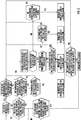
- FIG. 3 is a detailed flowchart of the device shown in FIG. 1 .
- a cooling system when a cooling system is in a cooling mode, whether the cooling system is operating is continuously monitored. If it is found that the system has been shut down for a longer duration than a second predefined period of time, steps S2.1 and S3.1 described above are performed; and when it is determined that a refrigerant leakage has occurred, a warning signal is sent.
- an operating parameter of an air-cooled heat pump system including reading an expansion valve opening degree, a supercooling degree, and a superheat degree from the air-cooled heat pump system; and whether the supercooling degree is less than a second predefined value is determined. If the supercooling degree is not less than the second predefined value, then a supercooling degree check is performed.
- the expansion valve opening degree is equal to a predefined opening degree is determined continuously; if the expansion valve opening degree is equal to the predefined opening degree, then a superheat degree check is performed; and if the expansion valve opening degree is not equal to the predefined opening degree, then a compressor discharge pressure check is performed.
- a cumulative score is respectively increased by a different value.
- the cumulative score reaches a predefined cumulative score, it is determined that a refrigerant leakage has occurred and a warning signal is sent.
- the cumulative score is increased by a first score; in the superheat degree check, if a superheat degree is greater than a sum of a superheat degree setting value and a third predefined value, the cumulative score is increased by a second score; in the compressor discharge pressure check, if a compressor discharge pressure is less than a first predefined pressure, the cumulative score is increased by a third score; and in the supercooling degree check, if a supercooling degree is less than a predefined supercooling degree, the cumulative score is increased by a fourth score.
- each of the checking steps described above can be used alone or in combination; and when a combination is performed, two or more than two or all of the checking steps can be used.
- an initial value of the cumulative score is 0; the first score is 5; the second score is 3; the third score is 2; and the fourth score is 1.
- the cumulative score reaches 15 (i.e., the predefined cumulative score)
- the device and the method for detecting a refrigerant leakage are applicable to an air source cooling-only cycle cooling system which is preferably air-cooled.
- the device and the method for detecting a refrigerant leakage can automatically detect whether a refrigerant leakage has occurred in a cooling system without using other apparatuses for manual detection, which effectively improves the operating efficiency of the cooling system and has good economic benefits.
Landscapes
- Engineering & Computer Science (AREA)
- Physics & Mathematics (AREA)
- Mechanical Engineering (AREA)
- Thermal Sciences (AREA)
- General Engineering & Computer Science (AREA)
- Air Conditioning Control Device (AREA)
Applications Claiming Priority (1)
| Application Number | Priority Date | Filing Date | Title |
|---|---|---|---|
| CN201810330163.4A CN110375467B (zh) | 2018-04-13 | 2018-04-13 | 用于空气源单制冷系统的制冷剂泄露的检测装置和方法 |
Publications (1)
| Publication Number | Publication Date |
|---|---|
| EP3553424A1 true EP3553424A1 (de) | 2019-10-16 |
Family
ID=66101976
Family Applications (1)
| Application Number | Title | Priority Date | Filing Date |
|---|---|---|---|
| EP19167627.9A Pending EP3553424A1 (de) | 2018-04-13 | 2019-04-05 | Vorrichtung und verfahren zur detektion von kältemittelleckagen eines luftquellenkühlsystems |
Country Status (3)
| Country | Link |
|---|---|
| US (1) | US20190316821A1 (de) |
| EP (1) | EP3553424A1 (de) |
| CN (1) | CN110375467B (de) |
Families Citing this family (7)
| Publication number | Priority date | Publication date | Assignee | Title |
|---|---|---|---|---|
| JP6945731B2 (ja) * | 2018-05-02 | 2021-10-06 | 三菱電機株式会社 | 空気調和装置 |
| US11231198B2 (en) | 2019-09-05 | 2022-01-25 | Trane International Inc. | Systems and methods for refrigerant leak detection in a climate control system |
| CN110822629B (zh) * | 2019-11-22 | 2021-07-16 | 广东美的制冷设备有限公司 | 空调器冷媒泄露的检测方法、空调器及可读存储介质 |
| US12487008B2 (en) | 2022-01-14 | 2025-12-02 | Trane International Inc. | Method of commissioning an HVAC system |
| US12117191B2 (en) | 2022-06-24 | 2024-10-15 | Trane International Inc. | Climate control system with improved leak detector |
| CN115164349B (zh) * | 2022-06-30 | 2024-01-26 | 海信空调有限公司 | 空调 |
| CN115325736B (zh) * | 2022-10-17 | 2023-04-07 | 杭州长川科技股份有限公司 | 制冷系统泄漏类型的确定方法、装置、制冷模块及系统 |
Citations (5)
| Publication number | Priority date | Publication date | Assignee | Title |
|---|---|---|---|---|
| EP0837293A2 (de) * | 1996-10-18 | 1998-04-22 | Matsushita Electric Industrial Co., Ltd. | Kühlgerät |
| EP1731857A1 (de) * | 2004-01-21 | 2006-12-13 | Mitsubishi Denki Kabushiki Kaisha | Vorrichtungsdiagnosevorrichtung, gefrierzyklusvorrichtung, fluidkreislaufdiagnoseverfahren, vorrichtungsüberwachungssystem und gefrierzyklusüberwachungssystem |
| JP2017053566A (ja) * | 2015-09-10 | 2017-03-16 | ジョンソンコントロールズ ヒタチ エア コンディショニング テクノロジー(ホンコン)リミテッド | 冷凍サイクル装置 |
| CN106524418A (zh) * | 2016-11-10 | 2017-03-22 | 邯郸美的制冷设备有限公司 | 空调器冷媒泄露的检测方法、检测系统和空调器 |
| CN107289599A (zh) * | 2017-08-10 | 2017-10-24 | 四川长虹电器股份有限公司 | 一种检测空调冷媒泄露量的装置和方法 |
Family Cites Families (5)
| Publication number | Priority date | Publication date | Assignee | Title |
|---|---|---|---|---|
| US20050126190A1 (en) * | 2003-12-10 | 2005-06-16 | Alexander Lifson | Loss of refrigerant charge and expansion valve malfunction detection |
| TWI395912B (zh) * | 2010-07-15 | 2013-05-11 | China Steel Corp | 空調機組運轉保護裝置 |
| US8469551B2 (en) * | 2010-10-20 | 2013-06-25 | 3M Innovative Properties Company | Light extraction films for increasing pixelated OLED output with reduced blur |
| US10539353B2 (en) * | 2013-03-15 | 2020-01-21 | Daikin Applied Americas Inc. | Refrigerating apparatus and control device for refrigerating machine |
| WO2015004747A1 (ja) * | 2013-07-10 | 2015-01-15 | 三菱電機株式会社 | 冷凍サイクル装置 |
-
2018
- 2018-04-13 CN CN201810330163.4A patent/CN110375467B/zh active Active
-
2019
- 2019-04-05 EP EP19167627.9A patent/EP3553424A1/de active Pending
- 2019-04-11 US US16/381,627 patent/US20190316821A1/en not_active Abandoned
Patent Citations (5)
| Publication number | Priority date | Publication date | Assignee | Title |
|---|---|---|---|---|
| EP0837293A2 (de) * | 1996-10-18 | 1998-04-22 | Matsushita Electric Industrial Co., Ltd. | Kühlgerät |
| EP1731857A1 (de) * | 2004-01-21 | 2006-12-13 | Mitsubishi Denki Kabushiki Kaisha | Vorrichtungsdiagnosevorrichtung, gefrierzyklusvorrichtung, fluidkreislaufdiagnoseverfahren, vorrichtungsüberwachungssystem und gefrierzyklusüberwachungssystem |
| JP2017053566A (ja) * | 2015-09-10 | 2017-03-16 | ジョンソンコントロールズ ヒタチ エア コンディショニング テクノロジー(ホンコン)リミテッド | 冷凍サイクル装置 |
| CN106524418A (zh) * | 2016-11-10 | 2017-03-22 | 邯郸美的制冷设备有限公司 | 空调器冷媒泄露的检测方法、检测系统和空调器 |
| CN107289599A (zh) * | 2017-08-10 | 2017-10-24 | 四川长虹电器股份有限公司 | 一种检测空调冷媒泄露量的装置和方法 |
Also Published As
| Publication number | Publication date |
|---|---|
| US20190316821A1 (en) | 2019-10-17 |
| CN110375467A (zh) | 2019-10-25 |
| CN110375467B (zh) | 2022-07-05 |
Similar Documents
| Publication | Publication Date | Title |
|---|---|---|
| EP3553424A1 (de) | Vorrichtung und verfahren zur detektion von kältemittelleckagen eines luftquellenkühlsystems | |
| CN110895023B (zh) | 一种空调冷媒泄漏检测方法及空调器 | |
| JP6341808B2 (ja) | 冷凍空調装置 | |
| CN100549573C (zh) | 空气调节器及其制冷剂量判定方法 | |
| CN110375466B (zh) | 用于空气源热泵系统的制冷剂泄露的检测装置和方法 | |
| JP5405161B2 (ja) | 空気調和装置およびエネルギー機器 | |
| CN101048713A (zh) | 检测制冷系统性能降低的系统和方法 | |
| JP6101815B2 (ja) | 冷凍サイクル装置 | |
| CN110836519B (zh) | 一种空调器冷媒泄漏检测方法及检测系统 | |
| JP6444577B1 (ja) | 空気調和機 | |
| CN101424469A (zh) | 面向冷冻空调装置的制冷剂填充装置以及制冷剂填充方法 | |
| JPWO2019053858A1 (ja) | 冷凍サイクル装置および冷凍装置 | |
| CN110878985A (zh) | 一种空调器冷媒泄漏检测的方法及装置 | |
| CN115614918B (zh) | 一种空调器的缺冷媒检测方法、装置及空调器 | |
| CN115371204B (zh) | 电子膨胀阀故障判定方法及相关装置 | |
| JP2005257219A (ja) | 空気調和機 | |
| JP2019203620A (ja) | 冷凍サイクル装置 | |
| JP2013204871A (ja) | 空気調和機 | |
| JP6611929B2 (ja) | 冷凍装置 | |
| JP2021081187A (ja) | 空気調和装置 | |
| CN105157295A (zh) | 一种制冷系统及其控制方法、控制装置 | |
| US10845098B2 (en) | Air conditioner | |
| KR20150117396A (ko) | 냉장고의 냉매 누설 감지 방법 | |
| JP2010007997A (ja) | 空気調和装置の冷媒量判定方法および空気調和装置 | |
| KR20160099938A (ko) | 냉장고의 냉매 누설 감지 방법 |
Legal Events
| Date | Code | Title | Description |
|---|---|---|---|
| PUAI | Public reference made under article 153(3) epc to a published international application that has entered the european phase |
Free format text: ORIGINAL CODE: 0009012 |
|
| STAA | Information on the status of an ep patent application or granted ep patent |
Free format text: STATUS: THE APPLICATION HAS BEEN PUBLISHED |
|
| AK | Designated contracting states |
Kind code of ref document: A1 Designated state(s): AL AT BE BG CH CY CZ DE DK EE ES FI FR GB GR HR HU IE IS IT LI LT LU LV MC MK MT NL NO PL PT RO RS SE SI SK SM TR |
|
| AX | Request for extension of the european patent |
Extension state: BA ME |
|
| STAA | Information on the status of an ep patent application or granted ep patent |
Free format text: STATUS: REQUEST FOR EXAMINATION WAS MADE |
|
| 17P | Request for examination filed |
Effective date: 20200330 |
|
| RBV | Designated contracting states (corrected) |
Designated state(s): AL AT BE BG CH CY CZ DE DK EE ES FI FR GB GR HR HU IE IS IT LI LT LU LV MC MK MT NL NO PL PT RO RS SE SI SK SM TR |
|
| STAA | Information on the status of an ep patent application or granted ep patent |
Free format text: STATUS: EXAMINATION IS IN PROGRESS |
|
| 17Q | First examination report despatched |
Effective date: 20210311 |