EP3553430B1 - Réfrigérateur comprenant un espace vide - Google Patents
Réfrigérateur comprenant un espace vide Download PDFInfo
- Publication number
- EP3553430B1 EP3553430B1 EP19172995.3A EP19172995A EP3553430B1 EP 3553430 B1 EP3553430 B1 EP 3553430B1 EP 19172995 A EP19172995 A EP 19172995A EP 3553430 B1 EP3553430 B1 EP 3553430B1
- Authority
- EP
- European Patent Office
- Prior art keywords
- inner case
- outer case
- case
- refrigerator
- reinforcing frame
- Prior art date
- Legal status (The legal status is an assumption and is not a legal conclusion. Google has not performed a legal analysis and makes no representation as to the accuracy of the status listed.)
- Active
Links
Images





Classifications
-
- F—MECHANICAL ENGINEERING; LIGHTING; HEATING; WEAPONS; BLASTING
- F25—REFRIGERATION OR COOLING; COMBINED HEATING AND REFRIGERATION SYSTEMS; HEAT PUMP SYSTEMS; MANUFACTURE OR STORAGE OF ICE; LIQUEFACTION SOLIDIFICATION OF GASES
- F25D—REFRIGERATORS; COLD ROOMS; ICE-BOXES; COOLING OR FREEZING APPARATUS NOT OTHERWISE PROVIDED FOR
- F25D23/00—General constructional features
- F25D23/06—Walls
- F25D23/062—Walls defining a cabinet
-
- F—MECHANICAL ENGINEERING; LIGHTING; HEATING; WEAPONS; BLASTING
- F25—REFRIGERATION OR COOLING; COMBINED HEATING AND REFRIGERATION SYSTEMS; HEAT PUMP SYSTEMS; MANUFACTURE OR STORAGE OF ICE; LIQUEFACTION SOLIDIFICATION OF GASES
- F25D—REFRIGERATORS; COLD ROOMS; ICE-BOXES; COOLING OR FREEZING APPARATUS NOT OTHERWISE PROVIDED FOR
- F25D11/00—Self-contained movable devices, e.g. domestic refrigerators
-
- F—MECHANICAL ENGINEERING; LIGHTING; HEATING; WEAPONS; BLASTING
- F25—REFRIGERATION OR COOLING; COMBINED HEATING AND REFRIGERATION SYSTEMS; HEAT PUMP SYSTEMS; MANUFACTURE OR STORAGE OF ICE; LIQUEFACTION SOLIDIFICATION OF GASES
- F25D—REFRIGERATORS; COLD ROOMS; ICE-BOXES; COOLING OR FREEZING APPARATUS NOT OTHERWISE PROVIDED FOR
- F25D23/00—General constructional features
-
- F—MECHANICAL ENGINEERING; LIGHTING; HEATING; WEAPONS; BLASTING
- F25—REFRIGERATION OR COOLING; COMBINED HEATING AND REFRIGERATION SYSTEMS; HEAT PUMP SYSTEMS; MANUFACTURE OR STORAGE OF ICE; LIQUEFACTION SOLIDIFICATION OF GASES
- F25D—REFRIGERATORS; COLD ROOMS; ICE-BOXES; COOLING OR FREEZING APPARATUS NOT OTHERWISE PROVIDED FOR
- F25D23/00—General constructional features
- F25D23/02—Doors; Covers
-
- F—MECHANICAL ENGINEERING; LIGHTING; HEATING; WEAPONS; BLASTING
- F25—REFRIGERATION OR COOLING; COMBINED HEATING AND REFRIGERATION SYSTEMS; HEAT PUMP SYSTEMS; MANUFACTURE OR STORAGE OF ICE; LIQUEFACTION SOLIDIFICATION OF GASES
- F25D—REFRIGERATORS; COLD ROOMS; ICE-BOXES; COOLING OR FREEZING APPARATUS NOT OTHERWISE PROVIDED FOR
- F25D23/00—General constructional features
- F25D23/06—Walls
-
- F—MECHANICAL ENGINEERING; LIGHTING; HEATING; WEAPONS; BLASTING
- F25—REFRIGERATION OR COOLING; COMBINED HEATING AND REFRIGERATION SYSTEMS; HEAT PUMP SYSTEMS; MANUFACTURE OR STORAGE OF ICE; LIQUEFACTION SOLIDIFICATION OF GASES
- F25D—REFRIGERATORS; COLD ROOMS; ICE-BOXES; COOLING OR FREEZING APPARATUS NOT OTHERWISE PROVIDED FOR
- F25D23/00—General constructional features
- F25D23/06—Walls
- F25D23/065—Details
- F25D23/066—Liners
-
- F—MECHANICAL ENGINEERING; LIGHTING; HEATING; WEAPONS; BLASTING
- F25—REFRIGERATION OR COOLING; COMBINED HEATING AND REFRIGERATION SYSTEMS; HEAT PUMP SYSTEMS; MANUFACTURE OR STORAGE OF ICE; LIQUEFACTION SOLIDIFICATION OF GASES
- F25D—REFRIGERATORS; COLD ROOMS; ICE-BOXES; COOLING OR FREEZING APPARATUS NOT OTHERWISE PROVIDED FOR
- F25D23/00—General constructional features
- F25D23/06—Walls
- F25D23/065—Details
- F25D23/067—Supporting elements
-
- F—MECHANICAL ENGINEERING; LIGHTING; HEATING; WEAPONS; BLASTING
- F25—REFRIGERATION OR COOLING; COMBINED HEATING AND REFRIGERATION SYSTEMS; HEAT PUMP SYSTEMS; MANUFACTURE OR STORAGE OF ICE; LIQUEFACTION SOLIDIFICATION OF GASES
- F25D—REFRIGERATORS; COLD ROOMS; ICE-BOXES; COOLING OR FREEZING APPARATUS NOT OTHERWISE PROVIDED FOR
- F25D2201/00—Insulation
- F25D2201/10—Insulation with respect to heat
- F25D2201/14—Insulation with respect to heat using subatmospheric pressure
Definitions
- This invention relates to refrigerators, and more particularly to a refrigerator in which a vacuum space is formed between an outer case and an inner case of a body thereof for enhancing a heat insulating function.
- the refrigerator is a domestic appliance which forms a storage chamber temperature below zero or above zero degree for refrigerated or frozen storage of a storage object.
- the refrigerator is provided with the body having the storage space formed therein for storage of the storage object, and a door rotatably or slidably mounted to the body for opening/closing the storage space.
- the body has the inner case to form the storage space, the outer case which houses the inner case, and an insulating material arranged between the inner case and the outer case.
- the insulating material suppresses an external temperature from influencing the temperature of the storage space.
- US 3 230 726 A presents a thermally insulated container comprising an outer shell, an inner storage chamber for storing materials, said shell and said chamber being (a) spaced from one another so as to define an intervening thermally insulating evacuable space therebetween, (b) subject to movement relative to each other due to thermal expansion and contraction when in use and (c) each pro-vided with an opening, said openings being aligned to provide a passageway into the chamber, and gas-impermeable, elastomeric, low heat conducting connecting means for sealing the evacuable space so as to maintain a vacuum in the evacuable space upon the evacuating of said space by minimizing entry of air into said space through said openings, said connecting means being composed of a gas-impermeable elastomeric material of low thermal conductivity that is gas-tightly attached to both the shell and the chamber and that is capable of deforming without failure so as to allow for the movement of the shell and chamber relative to each other due to thermal expansion and contraction.
- FR 841 436 A presents a device for the construction of walls for refrigerated cabinets, using a special synthetic plastic material obtained by the condensation of urea formaldehyde.
- the material which is already by itself insulating, soundproof and anti-vibration, is used in the form of hollow elements having a single seal closed by a tight seal, in which the insulation is obtained by creating the vacuum inside or by introducing dehydrated air or other thermally insulating fluid into it.
- EP 0 071 090 A1 presents a refrigerator with vacuum insulation between at inner case and an outer case, the vacuum space comprising reinforcing members.
- this invention is directed to a refrigerator.
- An object of this invention is to provide a refrigerator in which a vacuum space is formed between an outer case and an inner case for enhancing a heat insulating function and making an outside volume thereof compact.
- a refrigerator includes a body having a storage space for storing a predetermined storage object, wherein the body includes an inner case having the storage space, an outer case having an inside surface spaced a predetermined gap from an outside surface of the inner case to house the inner case, and a vacuum space provided between the inner case and the outer case sealed to maintain a vacuum state for heat insulating between the inner case and the outer case.
- the refrigerator further includes a supporting portion provided to contact with, and support, the outside surface of the inner case and the inside surface of the outer case to maintain a spaced state of the inner case and the outer case
- the refrigerator further includes a reinforcing member mounted to at least one of the outside surface of the inner case and the inside surface of the outer case for reinforcing strength of the inner case or the outer case.
- the reinforcing member is a reinforcing rib projected from at least one of the outside surface of the inner case or the inside surface of the outer case to a height lower than a width of the vacuum space formed between the inner case and the outer case.
- the reinforcing rib is plural arranged at the outside surface of the inner case or the inside surface of the outer case spaced from one another.
- the reinforcing rib includes inside reinforcing ribs provided to the outside surface of the inner case, and outside reinforcing ribs provided to an inside surface of the outer case, wherein the inside reinforcing ribs and the outside reinforcing ribs are arranged alternately not to interfere with each other
- At least one of the inside reinforcing ribs and the outside reinforcing ribs are arranged to cross one another to reinforce strength of at least one of the inner case and the outer case.
- the reinforcing rib is arranged at the outside surface of the inner case or at the inside surface of the outer case in a first direction
- the reinforcing rib includes a first reinforcing rib arranged at at least one of the outside surface of the inner case or the inside surface of the outer case in the first direction, and a second reinforcing rib arranged in a second direction which crosses the first direction to cross the first reinforcing rib.
- the reinforcing rib has a forming portion provided to, and projected from, at least one of the inner case and the outer case for reinforcing strength of the inner case or the outer case.
- the forming portion is plural formed in the first direction.
- the forming portion formed in the first direction includes an inside forming portion formed at the inner case, and an outside forming portion formed at the outer case.
- the refrigerator further includes a reinforcing frame provided to at least one of the outside surface of the inner case and the inside surface of the outer case, arranged in a direction to cross a direction in which the forming portion is arranged for reinforcing strength of the inner case or the outer case.
- the reinforcing frame arranged at the outside surface of the inner case is arranged in a ring shape surrounding the outside surface of the inner case connected end to end.
- the reinforcing frame arranged at the inside surface of the outer case is arranged in a ring shape for supporting the inside surface of the outer case connected along the inside surface of the outer case.
- the reinforcing frame has a height smaller than a width of the vacuum space formed between the inner case and the outer case.
- the forming portion includes a first forming portion arranged in the first direction, and a second forming portion arranged in the second direction which crosses the first direction.
- the refrigerator further includes a porous material arranged in the vacuum space for preventing at least one of heat radiation, and heat conduction caused by gas between the inner case and the outer case from taking place.
- the refrigerator further includes a getter arranged in the vacuum space for absorbing gas from the vacuum space.
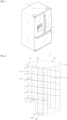
- the refrigerator includes a body 1 having a storage chamber formed therein, a first door 4 rotatably provided to the body 1, and a second door 5 slidably provided to the body 1.
- the first door 4 has a function of, but not limited to, opening/closing a refrigerating chamber in the storage chamber
- the second door 5 has a function of, but not limited to, opening/closing a freezing chamber in the storage chamber.
- FIG. 2 illustrates a perspective view of a body of the refrigerator in accordance with a first, non-claimed example, with an outer case thereof removed from a top side and a side thereof
- the body 1 has a structure including an inner case 110 which forms a predetermined storage space 111 therein, and an outer case 120 which forms a space for housing the inner case 110 therein and surrounds the inner case 110.
- the inner case 110 and the outer case 120 function as a wall which forms an exterior of the body 1 and the storage space 111 therein.
- the outer case 120 and the inner case 110 are spaced from each other to form a space which has no additional insulating material arranged therein, but only a vacuum maintained therein for heat insulation.
- the vacuum space 130 formed between the outer case 120 and the inner case 110 maintains a state in which a medium which transmits heat between the inner case 110 and the outer case 120 is removed therefrom.
- a supporting portion 140 is required, which serves as a spacer that maintains a gap between the inner case 110 and the outer case 120.
- the supporting portion 140 is arranged to be in contact with an outside surface of the inner case 110 and an inside surface of the outer case 120.
- the supporting portion 140 may be provided such that the supporting portion 140 is arranged projected from the outside surface of the inner case 110 to make a surface to surface contact with the inside surface of the outer case 120, or is arranged projected from the inside surface of the outer case 120 to make surface to surface contact with the outside surface of the inner case 110.
- the supporting portion 140 may be arranged both at the inside surface of the outer case 120 and at the outside surface of the inner case 110.
- positions of the supporting portion 140 arranged at the inside surface of the outer case 120 and the positions of the supporting portion 140 arranged at the outside surface of the inner case 110 are, not overlap, but alternate, with one another.
- reinforcing ribs 150 may be provided to the outside surface of the inner case 110 and the inside surface of the outer case 120 for reinforcing strength thereof, additionally.
- the inner case 110 and the outer case 120 are not thick, the inner case 110 and the outer case 120 are liable to distort by an external impact, or deform at the time of evacuation to form the vacuum space 130.
- the reinforcing ribs 150 are arranged on an outside surface of the inner case 110 or the inside surface of the outer case 120 for reinforcing the strength.
- the reinforcing ribs 150 are plural, and arranged spaced from one another on the outside surface of the inner case 110 or on the inside surface of the outer case 120.
- a getter 160 is provided to the vacuum space 130 for collecting gas liable to present in the vacuum space 130, thereby preventing heat transfer caused by the gas liable to form by a chemical reaction of the outer case 120 or the inner case 110, in advance.
- the getter 160 is provided to a ceiling or a bottom of the vacuum space 130.
- the getter 160 has a substance which has a strong action of adsorbing residual gas molecules from the vacuum space 130 or making a chemical reaction therewith to form a solid compound.
- the getter 160 Since it is difficult to obtain an adequate vacuum in the vacuum space 130 only with a vacuum pump technically, and it also costs high, the getter 160 is used.
- getters 160 There are different kinds of getters 160. If the getter 160 has a strong adsorbing action, the getter 160 is called as a flashed getter, and if the getter 160 is in a gaseous state with a strong chemical reaction, the getter 160 is called as a non-evaporable getter.
- the getter 160 is formed of active charcoal, barium, magnesium, zirconium, red phosphorus, and so on.
- the vacuum space 130 has a front covered with a front cover 170 which connects and seals front edges of the inner case 110 and the outer case 120.
- FIG. 3 illustrates the inner case 110
- FIG. 3B illustrates the outer case 120.
- the reinforcing ribs 150 are arranged in a front/rear direction and a up/down direction of the inner case 110 and the outer case 120, to cross with one another, the reinforcing ribs 150 may be arranged in any one direction.
- first reinforcing rib 150 arranged in a first direction (The front/rear direction)
- second reinforcing rib 152 the reinforcing rib 150 arranged in a second direction
- first and second reinforcing ribs 151 and 152 are arranged to cross each other perpendicularly.
- the supporting portion 140 is arranged on a surface between the reinforcing ribs 150.
- reinforcing ribs 150 arranged on the inside surface of the outer case 120 are called as outside reinforcing ribs 150a
- the reinforcing ribs 150 arranged on the outside surface of the inner case 110 are called as inside reinforcing ribs 150b
- the outside reinforcing ribs 150a and the inside reinforcing ribs 150b are spaced not overlap with each other not to interfere with each other.
- the inside reinforcing ribs 150b and the outside reinforcing ribs 150a are arranged alternately in the vacuum space 130.
- the reinforcing ribs 150 are arranged in an order of the inside reinforcing ribs 150b-the outside reinforcing ribs 150a-the inside reinforcing ribs 150b-the outside reinforcing ribs 150a.
- At least one of the inside reinforcing ribs 150a ad the outside reinforcing ribs 150b are arranged in the front/rear direction or the up/down direction of the inner case 110 or the outer case 120 to cross each other.
- reinforcing ribs 150 may perform a reinforcing function even if the reinforcing ribs 150 are arranged in one direction, if crossed, a strength reinforcing effect is great, significantly.
- the supporting portion 140 is arranged between the reinforcing ribs 150 in the up/down direction and the front/rear direction spaced from one another in plural.
- FIG. 4 illustrates a perspective view of a portion of a vacuum space 130, showing the inside reinforcing ribs 150a and the outside reinforcing ribs 150b arranged spaced from each other not to overlap with each other.
- each of the outside reinforcing ribs 150b and the inside reinforcing ribs 150a has a projected length or a projected height smaller than the vacuum space 130, for preventing the outside reinforcing ribs 150b from being in contact with the outside surface of the inner case 110, or the inside reinforcing ribs 150a from being in contact with the inside surface of the outer case 120.
- the projected length or the projected height of each of the outside reinforcing ribs 150b and the inside reinforcing ribs 150a is formed smaller than the width of the vacuum space 130.
- the supporting portion 140 has a size matched to the width of the vacuum space 130 for the supporting portion 140 to perform a function of maintaining the width of the vacuum space 130.
- the heat transfer is liable to take place through the supporting portion 140, it is preferable that a number of the supporting portion 140 is minimized as far as the width of the vacuum space 130 is maintained by the supporting portion 140.
- FIG. 5 illustrates a perspective view of a body of the refrigerator in accordance with a second, non-claimed example, with an outer case thereof removed from a top side and a side thereof, showing the reinforcing ribs 150 arranged in one direction in the vacuum space 130.
- the reinforcing ribs 150 may be arranged in the up/down direction or the left/right direction.
- FIGS. 6A and 6B illustrate perspective views of an inner case and an outer case of a body of a refrigerator in accordance with a second non-claimed example respectively, showing the reinforcing ribs 150 arranged at the inner case 110 and the outer case 120 respectively, the reinforcing ribs 150 may be arranged only at the inner case 110 or only at the outer case 120.
- the inside reinforcing ribs 150a are arranged at side surfaces, a top surface and an underside surface of the outside wall of the inner case 110 in the front/rear direction
- the outside reinforcing ribs 150b are arranged at side surfaces, a top surface and a bottom surface of the inside wall of the outer case 120 in the front/rear direction.
- the supporting portion 140 is arranged between the reinforcing ribs 150.
- a projected length or projected height of the reinforcing rib 150 is smaller than a projected height or a projected length of the supporting portion 140.
- the inside reinforcing ribs 150a and the outside reinforcing ribs 150b are provided, it is preferable that the inside reinforcing ribs 150a and the outside reinforcing ribs 150b are arranged spaced from each other or alternately not to interfere with each other.
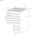
- FIG. 7 illustrates a perspective view of a body of the refrigerator in accordance with a third, non-claimed example
- FIGS. 8A and 8B illustrate perspective views of an inner case and an outer case of a body of a refrigerator in accordance with a third, non-claimed example, showing forming portion s 250 for reinforcing strength of the inner case 210 and the outer case 220 instead of the reinforcing ribs 150.
- the forming portion 250 is continuous curved surfaces of the inner case 210 and the outer case 220 formed in one direction along the surfaces of the inner case 210 and the outer case 220.
- the forming portion 250 in the inner case 210 is called as an inside forming portion 250a, and the forming portion 250 in the outer case 220 is called as an outside forming portion 250b.
- the inside forming portion 250a are projected inward from sides, a top side, a bottom side and a rear side of the inner case 210. However, the inside forming portion 250a may be projected outward.
- outside forming portion 250b is also projected outward from sides, a top side, a bottom side and a rear side of the outer case 220.
- an extent of projection of the forming portion 250 is smaller than the width of the vacuum space 230 between the inner case 210 and the outer case 220.
- this is for preventing the heat transfer between the inner case 210 and outer case 220 through the forming portion 250 from taking place.
- a supporting portion 240 provided to the outside surface of the inner case 210 or to the inside surface of the inner case 210 for maintaining a gap or a width of the vacuum space 230 between the inner case 210 and the outer case 220.
- the supporting portion 240 is formed on a flat surface provided adjacent to the forming portion 250.
- the inside forming portion 250a and the outside forming portion 250b are arranged not to be in contact or interfere with each other.
- a minimized width of the vacuum space 230 owing to arrangement of the inside forming portion 250a and the outside forming portion 250b may contribute to make the refrigerator compact.
- the forming portion 250 includes a first forming portion 251 arranged in a first direction, or a front/rear direction, and a second forming portion 252 in a second direction to cross the first direction, or an up/down direction or a left/right direction.
- the first forming portion 251 and the second forming portion 252 are arranged to cross each other for making effective strength reinforcement of the inner case 210 and the outer case 220.
- first forming portion 251 are plural spaced from one another, and the second forming portion 252 are also plural spaced from one another.
- first forming portion 251 and the second forming portion 252 are provided to cross each other to reinforce the strength of the inner case 210 and the outer case 220, no additional reinforcing member will be required.
- An unexplained reference numeral 260 denotes a getter, and 270 denotes a front cover for blocking a front of the vacuum space 230 to seal the vacuum space 230.
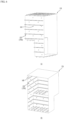
- FIG. 9 illustrates a perspective view of a body of the refrigerator in accordance with a fourth, non-claimed example
- FIGS. 10A and 10B illustrate perspective views of an inner case and an outer case of a body of a refrigerator in accordance with a fourth, non-claimed example, wherein the case also has an inner case 310 and an outer case 320 which houses the inner case 310.
- a supporting portion 340 provided to an outside surface of the inner case 310 or to the inside surface of the outer case 320 for maintaining a gap between the inner case 310 and the outer case 320.
- a forming portion 350 in the fourth, non-claimed example is different from the forming portion 250 in the third, non-claimed example described with reference to FIGS. 7 , 8A and 8B in that the forming portion 350 in the fourth, non-claimed example is arranged in a particular direction, specifically, in a front/rear direction, continuously.
- the forming portion 350 may be arranged in a left/right direction or an up/down direction, continuously.
- one formed on the outer case 320 will be called as an outside forming portion 350b, and one formed on the inner case 310 will be called as an inside forming portion 350a.
- the forming portion 350 is arranged only in one of the first and second directions.
- the forming portion 350 arranged only in one direction thus has an advantage in that a structure of a mold for forming the case may become simpler than a case of FIGS. 7 , 8A and 8B .
- the forming portion 350 arranged only in one direction is in a superior position in view of time and cost to the case of FIGS. 7 , 8A and 8B , the forming portion 350 is in an inferior position in view of strength reinforcement.
- FIGS. 11A and 11B illustrate an entire perspective view and a partial perspective view of an inner case and a reinforcing frame 380 mounted to the inner case of a body of a refrigerator in accordance with a preferred embodiment of this invention respectively
- FIGS. 12A and 12B illustrate an entire perspective view and a partial perspective view of an outer case and a reinforcing frame 380 mounted to the outer case of a body of a refrigerator in accordance with a preferred embodiment of this invention, respectively.
- the reinforcing frame 380 arranged at the inner case 310 is defined as an inside reinforcing frame 380a
- the reinforcing frame 380 arranged at the outer case 320 is defined as an outside reinforcing frame 380b.
- the inside reinforcing frame 380a is provided in a shape of a band or a ring which surrounds the outside surface of the inner case 310 in plural space from one another.
- the inside reinforcing frame 380a By arranging the inside reinforcing frame 380a to cross a direction of arrangement of the inside forming portion 350a, to form a resistance force against external force applied in a direction the inside forming portion 350a fails to cover, deformation of the inner case may be prevented.
- the inside reinforcing frame 380a is arranged in the left/right direction at the top side surface and the bottom side surface of the inner case 310, and in an up/down direction at the sides of the inner case 310.
- the inside reinforcing frame 380a is arranged in conformity with shapes of the projection P and the recess R.
- a portion of the inside reinforcing frame 380a in contact with the projection P is arranged projected outward as much as the projection, and a portion of the inside reinforcing frame 380a in contact with the recess R between the inside forming portions 350a is arranged in a recessed shape.
- the outside reinforcing frame 380b is arranged at an inside surface of the outer case 320 for reinforcing strength of the outer case 320.
- the outside reinforcing frame 380b is provided in a shape of a band or a ring (A closed loop type) which is arranged along the inside surface of the outer case 320 in plural spaced from one another.
- outside reinforcing frame 380b By arranging the outside reinforcing frame 380b to cross a direction of arrangement of the outside forming portion 350b, to form a resistance force against external force applied in a direction the outside forming portion 350b fails to cover, deformation of the outer case 320 may be prevented.
- the outside reinforcing frame 380b is arranged in the left/right direction at the top side surface and the bottom side surface of an inside of the outer case 320, and in an up/down direction at the sides of the outer case 320.
- the outside reinforcing frame 380b is arranged in conformity with the shapes of the projection P and the recess R.
- a portion of the outside reinforcing frame 380b in contact with the projection of the outside forming portion 350b is projected as much as the projection, and a portion of the outside reinforcing frame 380b in contact with the recess R between the outside forming portion s 350b is recessed inward more than the projected portion.
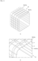
- FIG. 13 illustrates a cross section of the inside reinforcing frame 380a which is one of the reinforcing frames 380 arranged along the outside surface of the inner case 310.
- the inside reinforcing frame 380a has an "I" section or an "I” section laid down in a horizontal direction
- the "I" section has a top side 385 width and a bottom side 386 width larger than a middle portion 387.
- the inside reinforcing frame 380a has such a cross section for saving material while providing a high resistance force against an external force higher than an "I" without the top side 385 and the bottom side 386 with widths larger than the middle portion 387.
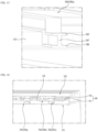
- FIG. 14 illustrates a section of a vacuum space in a refrigerator in accordance with a preferred embodiment of this invention, showing the inner case 310 and the outer side case 320 coupled together.
- each of the inside reinforcing frame 380a and the outside reinforcing frame 380b has a height lower than a height or a width of the vacuum space 330 between the inner case 310 and the outer case 320.
- the top side of the inside reinforcing frame 380a arranged at the outside surface of the inner case 310 is spaced a distance from the inside surface of the outer case 320.
- the bottom side of the outside reinforcing frame 380b arranged at the inside surface of the outer case 320 is spaced a distance from the outside surface of the inner case 310.
- the supporting portion 340 is in contact both with the inside surface of the outer case 320 and the outside surface of the inner case 310 for maintaining a gap between the outer case 320 and the inner case 310.
- FIG. 14 illustrates the supporting portion 340 including a base portion 341 which surrounds the inner case 310 and a supporting member 342 projected from the base portion 341 to one side.
- the supporting member 342 is arranged spaced from one another along the base portion 341.
- the supporting portion 340 is attached to the inside surface of the outer case 320 and the supporting member 342 is projected to the outside surface of the inner case 310 such that the supporting member 342 is in contact with the outside surface of the inner case 310.
- a space excluding the inside reinforcing frame 380a, the outside reinforcing frame 380b and the supporting portion 340 is an empty space to form the vacuum space 330.
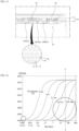
- FIG. 15 illustrates a section of a vacuum space 330 in a refrigerator in accordance with a preferred embodiment of this invention, showing a porous material 400 filled in the vacuum space 330.
- the vacuum space 330 is aiming at an ideal vacuum state by removing air and other remained gases therefrom to achieve a heat transfer rate of zero, it is difficult to exclude a case in which the vacuum space 330 contains a certain extent of gas.
- an insulating member 400 having voids or pores 401 of a predetermined size therein is arranged in the vacuum space 330.
- the void or pore 401 may be an activity space of a gas particle
- the insulating member 400 with the voids or pores 401 having small diameters limits the movement of the gas particle which may become a medium of the heat transfer to suppress the heat transfer.
- the insulating member 400 is different from the related art insulating material or a vacuum insulating material in that the vacuum space 330 serves as a major heat insulating function and the member with the pores 401 serves as a supplementary heat insulating function.
- FIG. 17 illustrates an exploded perspective view showing an order of assembly of the inner case 310, the outer case 320, the inside reinforcing frame 380a, the outside reinforcing frame 380b, and the supporting portion 340.
- the inner case 310 having the inside forming portion 350a is placed in the outer case 320 having the outside forming portion 350b.
- both a front and a rear of the outer case 320 are opened.
- the rear of the outer case 320 is opened for placing the inside reinforcing frame 380a, the outside reinforcing frame 380b, and the supporting portion 340 between the outer case 320 and the inner case 310 through the opened rear.
- the space is formed between the inner case 310 and the outer case 320.
- the space becomes the vacuum space 330, later.
- one of the supporting portions 340 is placed in the space (Step 1).
- one of the inside reinforcing frames 380a is placed in the space so as to be arranged at the outside surface of the inner case 310 spaced from the supporting portion 340(Step 2).
- inside reinforcing frame 380a is spaced from the inside surface of the outer case 320.
- one of the outside reinforcing frame 380b is placed in the space so as to be arranged at the inside surface of the outer case 320 spaced form the inside reinforcing frame 380a arranged thus (Step 3).
- outside reinforcing frame 380b is spaced from the outside surface of the inner case 310.
- the porous material 400 described with reference to FIG. 15 may be placed therein.
- the opened rear of the outer case 320 is closed with a rear cover 321.
- front edges of the inner case 310 and the outer case 320 are covered with a front cover 370, to seal the space.
- the space is evacuated, to make the space to be the vacuum space 330.
- the vacuum heat insulation permits fabrication of a refrigerator having a thin heat insulating layer.
- the refrigerator of this invention has the following advantages.
- the refrigerator of this invention has, not a general insulating material, but a vacuum space formed between the inner case and the outer case for suppressing heat transfer between the inner case and the outer case
- the refrigerator of this invention Since a heat insulating effect of the vacuum is significantly better than a heat insulating effect of the general insulating material, the refrigerator of this invention has a heat insulating effect better than the related art refrigerator.
- the heat insulating is made available only when a vacuum state is maintained regardless of the thickness (A gap between the inner case and the outer case, in a case of the general insulating material, it is required to make a thickness of the insulating material thicker to enhance the heat insulating effect, which thickness increase increases a size of the refrigerator.
- the refrigerator of this invention since the refrigerator of this invention permits to an outside size thereof while maintaining the storage space the same, a compact refrigerator can be provided.
Landscapes
- Engineering & Computer Science (AREA)
- Chemical & Material Sciences (AREA)
- Combustion & Propulsion (AREA)
- Physics & Mathematics (AREA)
- Mechanical Engineering (AREA)
- Thermal Sciences (AREA)
- General Engineering & Computer Science (AREA)
- Refrigerator Housings (AREA)
- Cold Air Circulating Systems And Constructional Details In Refrigerators (AREA)
Claims (9)
- Réfrigérateur comportant :un corps (1) ayant un espace de stockage (111) pour stocker un objet de stockage prédéterminé,dans lequel le corps (1) inclut :un caisson intérieur (310) ayant l'espace de stockage (111),un caisson extérieur (320) ayant une surface intérieure espacée par une distance prédéterminée d'une surface extérieure du caisson intérieur (310) pour recevoir le caisson intérieur (310),un espace sous vide (330) prévu entre le caisson intérieur (310) et le caisson extérieur (320) scellé pour maintenir un état de vide (330) pour l'isolation thermique entre le caisson intérieur (310) et le caisson extérieur (320),un sorbeur agencé dans l'espace sous vide (330) pour absorber du gaz à partir de l'espace sous vide (330),une partie de support (340) pour supporter un espace entre le caisson intérieur (310) et le caisson extérieur (320) ; etun élément de renfort (350) pour renforcer la résistance du caisson intérieur (310) ou du caisson extérieur (320),dans lequel la partie de support (340) est formée dans une forme de bossage ou de colonne ; etcaractérisé en ce quel'élément de renfort a une partie de formation (350) destinée à au moins un caisson parmi le caisson intérieur (310) et le caisson extérieur (320) et faisant saillie à partir de celui-ci, pour renforcer la résistance du caisson intérieur (310) ou du caisson extérieur (320), etdans lequel le réfrigérateur comporte en outre une armature de renfort (380) destinée à au moins une surface parmi la surface extérieure du caisson intérieur (310) et la surface intérieure du caisson extérieure (320), agencé dans une direction pour croiser une direction dans laquelle la partie de formation (350) est agencée pour renforcer la résistance du caisson intérieur (310) ou du caisson extérieur (320), l'armature de renfort (380) ayant une hauteur plus petite qu'une largeur de l'espace sous vide (330) formé entre le caisson intérieur (310) et le caisson extérieur (320), et dans lequel l'armature de renfort est placée dans l'espace sous vide (330) pour renforcer la résistance du caisson intérieur (310) et du caisson extérieur (320).
- Réfrigérateur selon la revendication 1, dans lequel la partie de support (340) est destinée à venir en contact avec, et supporter, la surface extérieure du caisson intérieur (310) et la surface intérieure du caisson extérieur (320) pour maintenir un état espacé du caisson intérieur (310) et du caisson extérieur (320).
- Réfrigérateur selon la revendication 1, dans lequel l'armature de renfort agencée sur la surface extérieure du caisson intérieur (310) est agencée avec une forme annulaire entourant la surface extérieure du caisson intérieur (310), assemblées bout à bout.
- Réfrigérateur selon la revendication 1, dans lequel l'armature de renfort agencée sur la surface intérieure du caisson extérieur (310) est agencée avec une forme annulaire pour supporter la surface intérieure du caisson extérieur (320) assemblée le long de la surface intérieure du caisson extérieur (320).
- Réfrigérateur selon la revendication 1, dans lequel l'armature de renfort (380) agencée sur le caisson intérieur (310) est définie comme une armature de renfort intérieure (380a), et l'armature de renfort (380) agencée sur le caisson extérieur (320) est définie comme une armature de renfort extérieure (380b), et dans lequel l'armature de renfort intérieure (380a) est agencée en forme de bande entourant la surface extérieure du caisson intérieur (310) espacées l'une de l'autre en pluralité, et dans lequel l'armature de renfort extérieure (380) est agencée en forme de bande ou d'anneau agencé le long de la surface intérieure du caisson extérieur (320) espacées l'une de l'autre en pluralité.
- Réfrigérateur selon la revendication 1, comportant en outre un matériau poreux agencé dans l'espace sous vide (330) pour empêcher l'occurrence d'au moins un phénomène parmi un rayonnement de chaleur et une conduction de chaleur provoqué par du gaz entre le caisson intérieur (310) et le caisson extérieur (320).
- Réfrigérateur selon la revendication 1, dans lequel des bords du caisson intérieur (310) et du caisson extérieur sont configurés pour être assemblés à un couvercle (370) pour sceller l'espace sous vide (330).
- Réfrigérateur selon la revendication 5, dans lequel l'armature de renfort intérieure (380a) et l'armature de renfort extérieure (380b) sont placées dans l'espace sous vide (330) pour renforcer la résistance du caisson intérieur (310) et du caisson extérieur (320) avant de sceller l'espace sous vide (330).
- Réfrigérateur selon la revendication 1, la partie de formation (350) comportant :une partie de formation intérieure (350a) faisant saillie vers l'extérieur à partir du caisson intérieur (310) pour supporter le caisson intérieur (310) ; etune partie de formation extérieure (350b) faisant saillie vers l'intérieur à partir du caisson extérieur (320) pour supporter le caisson extérieur (320).
Applications Claiming Priority (2)
| Application Number | Priority Date | Filing Date | Title |
|---|---|---|---|
| KR1020100105895A KR101898487B1 (ko) | 2010-10-28 | 2010-10-28 | 진공공간부를 구비하는 냉장고 |
| EP11008030.6A EP2447638B1 (fr) | 2010-10-28 | 2011-10-04 | Réfrigérateur comportant un espace vide |
Related Parent Applications (1)
| Application Number | Title | Priority Date | Filing Date |
|---|---|---|---|
| EP11008030.6A Division EP2447638B1 (fr) | 2010-10-28 | 2011-10-04 | Réfrigérateur comportant un espace vide |
Publications (2)
| Publication Number | Publication Date |
|---|---|
| EP3553430A1 EP3553430A1 (fr) | 2019-10-16 |
| EP3553430B1 true EP3553430B1 (fr) | 2023-06-21 |
Family
ID=44759381
Family Applications (2)
| Application Number | Title | Priority Date | Filing Date |
|---|---|---|---|
| EP11008030.6A Active EP2447638B1 (fr) | 2010-10-28 | 2011-10-04 | Réfrigérateur comportant un espace vide |
| EP19172995.3A Active EP3553430B1 (fr) | 2010-10-28 | 2011-10-04 | Réfrigérateur comprenant un espace vide |
Family Applications Before (1)
| Application Number | Title | Priority Date | Filing Date |
|---|---|---|---|
| EP11008030.6A Active EP2447638B1 (fr) | 2010-10-28 | 2011-10-04 | Réfrigérateur comportant un espace vide |
Country Status (11)
| Country | Link |
|---|---|
| US (7) | US8899068B2 (fr) |
| EP (2) | EP2447638B1 (fr) |
| KR (1) | KR101898487B1 (fr) |
| CN (2) | CN102455103B (fr) |
| AU (1) | AU2011232782B2 (fr) |
| BR (1) | BRPI1106655B1 (fr) |
| CA (1) | CA2755185C (fr) |
| ES (2) | ES2738107T3 (fr) |
| MX (1) | MX2011011133A (fr) |
| RU (1) | RU2488048C1 (fr) |
| TR (1) | TR201907088T4 (fr) |
Families Citing this family (69)
| Publication number | Priority date | Publication date | Assignee | Title |
|---|---|---|---|---|
| KR101147779B1 (ko) * | 2010-10-28 | 2012-05-25 | 엘지전자 주식회사 | 진공공간부를 구비하는 냉장고 |
| US9221210B2 (en) | 2012-04-11 | 2015-12-29 | Whirlpool Corporation | Method to create vacuum insulated cabinets for refrigerators |
| US9182158B2 (en) | 2013-03-15 | 2015-11-10 | Whirlpool Corporation | Dual cooling systems to minimize off-cycle migration loss in refrigerators with a vacuum insulated structure |
| US9140481B2 (en) | 2012-04-02 | 2015-09-22 | Whirlpool Corporation | Folded vacuum insulated structure |
| US10690391B2 (en) * | 2013-03-15 | 2020-06-23 | Whirlpool Corporation | Appliance using heated glass panels |
| US9689604B2 (en) | 2014-02-24 | 2017-06-27 | Whirlpool Corporation | Multi-section core vacuum insulation panels with hybrid barrier film envelope |
| US10052819B2 (en) | 2014-02-24 | 2018-08-21 | Whirlpool Corporation | Vacuum packaged 3D vacuum insulated door structure and method therefor using a tooling fixture |
| US9599392B2 (en) | 2014-02-24 | 2017-03-21 | Whirlpool Corporation | Folding approach to create a 3D vacuum insulated door from 2D flat vacuum insulation panels |
| DE102015006583A1 (de) * | 2014-06-16 | 2015-12-17 | Liebherr-Hausgeräte Lienz Gmbh | Temperiertes Behältnis |
| KR102366410B1 (ko) * | 2014-10-16 | 2022-02-23 | 삼성전자주식회사 | 냉장고 및 이에 구비되는 진공 단열재 |
| KR102273285B1 (ko) * | 2014-12-26 | 2021-07-06 | 삼성전자주식회사 | 냉장고 및 이에 구비되는 진공 단열재 |
| US9476633B2 (en) | 2015-03-02 | 2016-10-25 | Whirlpool Corporation | 3D vacuum panel and a folding approach to create the 3D vacuum panel from a 2D vacuum panel of non-uniform thickness |
| US10161669B2 (en) | 2015-03-05 | 2018-12-25 | Whirlpool Corporation | Attachment arrangement for vacuum insulated door |
| US9897370B2 (en) | 2015-03-11 | 2018-02-20 | Whirlpool Corporation | Self-contained pantry box system for insertion into an appliance |
| KR101758277B1 (ko) * | 2015-06-04 | 2017-07-14 | 엘지전자 주식회사 | 냉장고 |
| US9441779B1 (en) | 2015-07-01 | 2016-09-13 | Whirlpool Corporation | Split hybrid insulation structure for an appliance |
| KR102498210B1 (ko) | 2015-08-03 | 2023-02-09 | 엘지전자 주식회사 | 진공단열체 및 냉장고 |
| KR102456642B1 (ko) | 2015-08-03 | 2022-10-19 | 엘지전자 주식회사 | 진공단열체 및 냉장고 |
| KR102529852B1 (ko) | 2015-08-03 | 2023-05-08 | 엘지전자 주식회사 | 진공단열체 및 냉장고 |
| KR20170016188A (ko) | 2015-08-03 | 2017-02-13 | 엘지전자 주식회사 | 진공단열체 및 냉장고 |
| KR102502160B1 (ko) | 2015-08-03 | 2023-02-21 | 엘지전자 주식회사 | 진공단열체 및 냉장고 |
| KR102466469B1 (ko) * | 2015-08-03 | 2022-11-11 | 엘지전자 주식회사 | 진공단열체 및 냉장고 |
| KR102497139B1 (ko) | 2015-08-03 | 2023-02-07 | 엘지전자 주식회사 | 진공단열체 |
| WO2017023094A1 (fr) | 2015-08-03 | 2017-02-09 | Lg Electronics Inc. | Corps adiabatique sous vide et réfrigérateur |
| KR102525550B1 (ko) | 2015-08-03 | 2023-04-25 | 엘지전자 주식회사 | 진공단열체 및 냉장고 |
| KR102529853B1 (ko) | 2015-08-03 | 2023-05-08 | 엘지전자 주식회사 | 진공단열체, 진공단열체의 제조방법, 다공성물질패키지, 및 냉장고 |
| KR102442973B1 (ko) | 2015-08-03 | 2022-09-14 | 엘지전자 주식회사 | 진공단열체 및 냉장고 |
| KR102525551B1 (ko) | 2015-08-03 | 2023-04-25 | 엘지전자 주식회사 | 진공단열체 및 냉장고 |
| KR102447245B1 (ko) | 2015-08-03 | 2022-09-27 | 엘지전자 주식회사 | 진공단열체 및 냉장고 |
| KR102466470B1 (ko) | 2015-08-04 | 2022-11-11 | 엘지전자 주식회사 | 진공단열체 및 냉장고 |
| US11052579B2 (en) | 2015-12-08 | 2021-07-06 | Whirlpool Corporation | Method for preparing a densified insulation material for use in appliance insulated structure |
| US10429125B2 (en) | 2015-12-08 | 2019-10-01 | Whirlpool Corporation | Insulation structure for an appliance having a uniformly mixed multi-component insulation material, and a method for even distribution of material combinations therein |
| US12508751B2 (en) | 2015-12-08 | 2025-12-30 | Whirlpool Corporation | Insulation compaction device and method for forming an insulated structure for an appliance |
| US10222116B2 (en) | 2015-12-08 | 2019-03-05 | Whirlpool Corporation | Method and apparatus for forming a vacuum insulated structure for an appliance having a pressing mechanism incorporated within an insulation delivery system |
| US10041724B2 (en) | 2015-12-08 | 2018-08-07 | Whirlpool Corporation | Methods for dispensing and compacting insulation materials into a vacuum sealed structure |
| US10422573B2 (en) | 2015-12-08 | 2019-09-24 | Whirlpool Corporation | Insulation structure for an appliance having a uniformly mixed multi-component insulation material, and a method for even distribution of material combinations therein |
| US10422569B2 (en) | 2015-12-21 | 2019-09-24 | Whirlpool Corporation | Vacuum insulated door construction |
| US9840042B2 (en) | 2015-12-22 | 2017-12-12 | Whirlpool Corporation | Adhesively secured vacuum insulated panels for refrigerators |
| US9752818B2 (en) | 2015-12-22 | 2017-09-05 | Whirlpool Corporation | Umbilical for pass through in vacuum insulated refrigerator structures |
| US10610985B2 (en) | 2015-12-28 | 2020-04-07 | Whirlpool Corporation | Multilayer barrier materials with PVD or plasma coating for vacuum insulated structure |
| US10018406B2 (en) | 2015-12-28 | 2018-07-10 | Whirlpool Corporation | Multi-layer gas barrier materials for vacuum insulated structure |
| US10807298B2 (en) | 2015-12-29 | 2020-10-20 | Whirlpool Corporation | Molded gas barrier parts for vacuum insulated structure |
| US10030905B2 (en) | 2015-12-29 | 2018-07-24 | Whirlpool Corporation | Method of fabricating a vacuum insulated appliance structure |
| US11247369B2 (en) | 2015-12-30 | 2022-02-15 | Whirlpool Corporation | Method of fabricating 3D vacuum insulated refrigerator structure having core material |
| EP3443284B1 (fr) | 2016-04-15 | 2020-11-18 | Whirlpool Corporation | Structure de réfrigérateur à isolation sous vide, dotée de caractéristiques tridimensionnelles |
| US10712080B2 (en) | 2016-04-15 | 2020-07-14 | Whirlpool Corporation | Vacuum insulated refrigerator cabinet |
| US11320193B2 (en) | 2016-07-26 | 2022-05-03 | Whirlpool Corporation | Vacuum insulated structure trim breaker |
| WO2018034665A1 (fr) | 2016-08-18 | 2018-02-22 | Whirlpool Corporation | Compartiment de machine pour une structure isolée sous vide |
| EP3523584B1 (fr) * | 2016-10-04 | 2022-08-24 | Whirlpool Corporation | Formations structurales incorporées à l'intérieur d'une structure isolée sous vide |
| WO2018101954A1 (fr) | 2016-12-02 | 2018-06-07 | Whirlpool Corporation | Ensemble support de charnière |
| KR102658453B1 (ko) * | 2017-02-02 | 2024-04-17 | 엘지전자 주식회사 | 차량용 냉장고, 및 차량 |
| KR102499261B1 (ko) * | 2017-05-12 | 2023-02-13 | 삼성전자주식회사 | 단열재를 포함하는 냉장고 |
| KR102459784B1 (ko) | 2017-08-01 | 2022-10-28 | 엘지전자 주식회사 | 진공단열체 및 냉장고 |
| KR102449177B1 (ko) | 2017-08-01 | 2022-09-29 | 엘지전자 주식회사 | 진공단열체 및 냉장고 |
| KR102529116B1 (ko) | 2017-08-01 | 2023-05-08 | 엘지전자 주식회사 | 진공단열체, 진공단열체의 제작방법, 및 그 진공단열체로 단열하는 냉온장고 |
| KR102449175B1 (ko) | 2017-08-01 | 2022-09-29 | 엘지전자 주식회사 | 진공단열체 및 냉장고 |
| KR102427466B1 (ko) | 2017-08-01 | 2022-08-01 | 엘지전자 주식회사 | 차량, 차량용 냉장고, 및 차량용 냉장고의 제어방법 |
| KR102459786B1 (ko) | 2017-08-16 | 2022-10-28 | 엘지전자 주식회사 | 진공단열체 및 냉장고 |
| EP4502515A3 (fr) | 2017-12-18 | 2025-07-16 | Whirlpool Corporation | Appareil frigorifique doté d'un panneau mural comprenant une structure d'éclairage |
| EP3796812B1 (fr) * | 2018-05-23 | 2024-05-01 | Whirlpool Corporation | Ensemble charnière de dispositifs |
| US10907888B2 (en) | 2018-06-25 | 2021-02-02 | Whirlpool Corporation | Hybrid pigmented hot stitched color liner system |
| KR20200072257A (ko) * | 2018-12-12 | 2020-06-22 | 엘지전자 주식회사 | 진공단열체 및 냉장고 |
| US11460143B2 (en) * | 2019-05-21 | 2022-10-04 | Whirlpool Corporation | Collapsible pattern |
| US11150008B2 (en) * | 2020-01-16 | 2021-10-19 | Whirlpool Corporation | Cabinet reinforcing assembly |
| US11692763B2 (en) * | 2020-10-30 | 2023-07-04 | Whirlpool Corporation | Insulation materials for a vacuum insulated structure and methods of forming |
| US11614271B2 (en) | 2020-12-29 | 2023-03-28 | Whirlpool Corporation | Vacuum insulated structure with sheet metal features to control vacuum bow |
| DE102021200175A1 (de) * | 2021-01-11 | 2022-07-14 | BSH Hausgeräte GmbH | Innenbehälter mit spezifischer Wanddickengestaltung, Haushaltskältegerät, sowie Verfahren zum Herstellen eines Innenbehälters |
| US11448355B2 (en) | 2021-01-12 | 2022-09-20 | Whirlpool Corporation | Vacuum insulated refrigerator structure with feature for controlling deformation and improved air withdrawal |
| CN217262053U (zh) * | 2022-02-18 | 2022-08-23 | 上海思乐得不锈钢制品有限公司 | 一种冷链运输用箱体结构 |
Citations (1)
| Publication number | Priority date | Publication date | Assignee | Title |
|---|---|---|---|---|
| EP0071090A1 (fr) * | 1981-07-16 | 1983-02-09 | INDESIT INDUSTRIA ELETTRODOMESTICI ITALIANA S.p.A. | Système d'isolation thermique pour des dispositifs frigorifiques et procédé relatif à sa réalisation |
Family Cites Families (45)
| Publication number | Priority date | Publication date | Assignee | Title |
|---|---|---|---|---|
| US200088A (en) * | 1878-02-05 | Improvement in vehicle-wheels | ||
| US1588707A (en) * | 1924-07-23 | 1926-06-15 | Csiga Alexander | Vacuum ice chest |
| US1814114A (en) * | 1925-11-21 | 1931-07-14 | Insulation Corp | Refrigeration system and method |
| US2000882A (en) * | 1928-09-07 | 1935-05-07 | Stator Refrigeration Inc | Insulating housing |
| US1845353A (en) | 1928-12-14 | 1932-02-16 | Virgil K Snell | Heat-insulating construction |
| US1984261A (en) * | 1933-09-27 | 1934-12-11 | Foy Lillian Walker | Thermo container |
| FR841436A (fr) * | 1937-08-26 | 1939-05-19 | Dispositif pour la construction de parois pour armoires frigorifiques | |
| US3230726A (en) * | 1964-01-27 | 1966-01-25 | Union Carbide Corp | Elastomeric connecting means for double-walled containers |
| DE1964830U (de) * | 1967-03-18 | 1967-07-27 | Haas & Sohn Ernst W | Brennstoffbehaelter, insbesondere fuer oelbeheizte haushaltsgeraete. |
| ZA728342B (en) * | 1972-11-24 | 1974-07-31 | Rorand Ltd | Improvements in or relating to insulating materials |
| US3813137A (en) * | 1972-12-27 | 1974-05-28 | Whirlpool Co | Refrigerator cabinet |
| US3940195A (en) * | 1974-10-11 | 1976-02-24 | Whirlpool Corporation | Refrigeration cabinet |
| US4444821A (en) * | 1982-11-01 | 1984-04-24 | General Electric Company | Vacuum thermal insulation panel |
| US5175975A (en) * | 1988-04-15 | 1993-01-05 | Midwest Research Institute | Compact vacuum insulation |
| CN2062427U (zh) * | 1990-02-25 | 1990-09-19 | 赵根田 | 节能电冰箱 |
| DE4325399C2 (de) | 1993-07-29 | 1996-05-09 | Schott Glaswerke | Verwendung von temperaturdämmenden, plattenförmigen Systemelementen aus einer Mehrscheibenverglasung mit evakuierten Scheibenzwischenräumen zum Aufbau von Kühlräumen und Wärmekammern |
| CN2275051Y (zh) | 1996-09-28 | 1998-02-25 | 河南冰熊冷藏汽车厂 | 全封闭真空镀膜保温厢体结构 |
| DE19648305A1 (de) * | 1996-11-21 | 1998-05-28 | Bosch Siemens Hausgeraete | Wärmeisolierende Wandung |
| US6106449A (en) * | 1996-12-23 | 2000-08-22 | Vacupanel, Inc. | Vacuum insulated panel and container and method of production |
| JPH10281635A (ja) | 1997-04-07 | 1998-10-23 | Toshiba Corp | 易解体性冷蔵庫 |
| DK1023563T3 (da) * | 1997-10-16 | 2006-03-27 | Bsh Bosch Siemens Hausgeraete | Varmeisolerende væg |
| DE19745862A1 (de) | 1997-10-16 | 1999-04-22 | Bosch Siemens Hausgeraete | Wärmeisolierende Wandung |
| DE19907182A1 (de) | 1999-02-19 | 2000-08-24 | Bsh Bosch Siemens Hausgeraete | Wärmeisolierende Wand |
| DE29912917U1 (de) * | 1999-07-23 | 1999-11-18 | BSH Bosch und Siemens Hausgeräte GmbH, 81669 München | Wärmeisolierende Wandung |
| JP2002267343A (ja) | 1999-09-29 | 2002-09-18 | Chart Inc | 極低温フリーザー |
| IT1316769B1 (it) | 2000-02-18 | 2003-05-12 | Getters Spa | Pannello evacuato per isolamento termico con ridotta conduzione dicalore ai bordi |
| JP2002071088A (ja) | 2000-08-28 | 2002-03-08 | Matsuda Gijutsu Kenkyusho:Kk | 断熱パネル |
| RU2221972C2 (ru) | 2002-02-04 | 2004-01-20 | Закрытое акционерное общество "Завод холодильников Стинол" | Холодильник |
| TR200402415T1 (tr) | 2002-03-25 | 2005-10-21 | Ar�El�K A.�. | Yalıtılmış bir ünite ve üretim metodu |
| WO2003085339A1 (fr) * | 2002-04-05 | 2003-10-16 | Dometic Gmbh | Caisse de refrigerateur |
| CN1235010C (zh) * | 2002-06-06 | 2006-01-04 | 乐金电子(天津)电器有限公司 | 电冰箱出水口部防止绝热材料泄漏装置 |
| US20040226956A1 (en) | 2003-05-14 | 2004-11-18 | Jeff Brooks | Cryogenic freezer |
| NL1024810C2 (nl) | 2003-11-19 | 2005-05-23 | Level Holding Bv | Verbeterd vacuümisolatiepaneel. |
| CN1288407C (zh) * | 2003-12-25 | 2006-12-06 | 河南新飞电器有限公司 | 一种电冰箱门体的制造方法 |
| CN2711092Y (zh) | 2004-07-21 | 2005-07-20 | 余建岳 | 低温液体管束式集装箱的管筒形储罐 |
| KR100613051B1 (ko) | 2005-01-24 | 2006-08-16 | (주)상전정공 | 패널 보강구조를 갖는 진공 냉동탑차 |
| JP2007017053A (ja) | 2005-07-06 | 2007-01-25 | Matsushita Electric Ind Co Ltd | 冷蔵庫 |
| JP2007057199A (ja) | 2005-08-26 | 2007-03-08 | Matsushita Electric Ind Co Ltd | 冷蔵庫 |
| KR101203997B1 (ko) * | 2005-12-22 | 2012-11-23 | 삼성전자주식회사 | 냉장고 |
| KR100725834B1 (ko) * | 2006-03-31 | 2007-06-08 | 삼성광주전자 주식회사 | 냉장고 및 그 내부케이스의 제조방법 |
| US7954301B2 (en) | 2007-03-16 | 2011-06-07 | Ball Aerospace & Technologies Corp. | Integrated multilayer insulation |
| CN101742945B (zh) * | 2007-05-18 | 2012-11-14 | 梅特罗工业有限公司 | 用于环境控制柜的模块化隔热系统 |
| JP4463310B2 (ja) | 2008-03-07 | 2010-05-19 | 三井造船株式会社 | イオン源 |
| ITPN20080048A1 (it) | 2008-06-13 | 2009-12-14 | Karton Spa | "apparecchio frigorifero con cella perfezionata" |
| KR101060104B1 (ko) | 2008-07-29 | 2011-08-29 | 위니아만도 주식회사 | 냉장고용 인케이스 |
-
2010
- 2010-10-28 KR KR1020100105895A patent/KR101898487B1/ko active Active
-
2011
- 2011-09-23 US US13/241,725 patent/US8899068B2/en active Active
- 2011-10-04 EP EP11008030.6A patent/EP2447638B1/fr active Active
- 2011-10-04 EP EP19172995.3A patent/EP3553430B1/fr active Active
- 2011-10-04 TR TR2019/07088T patent/TR201907088T4/tr unknown
- 2011-10-04 ES ES11008030T patent/ES2738107T3/es active Active
- 2011-10-04 ES ES19172995T patent/ES2950616T3/es active Active
- 2011-10-06 AU AU2011232782A patent/AU2011232782B2/en active Active
- 2011-10-17 CA CA2755185A patent/CA2755185C/fr not_active Expired - Fee Related
- 2011-10-21 MX MX2011011133A patent/MX2011011133A/es active IP Right Grant
- 2011-10-27 CN CN201110332207.5A patent/CN102455103B/zh active Active
- 2011-10-27 CN CN201410654449.XA patent/CN104457117B/zh active Active
- 2011-10-27 RU RU2011143517/13A patent/RU2488048C1/ru active
- 2011-10-28 BR BRPI1106655-5A patent/BRPI1106655B1/pt not_active IP Right Cessation
-
2014
- 2014-11-04 US US14/532,144 patent/US9651292B2/en active Active
-
2017
- 2017-04-12 US US15/485,365 patent/US10337788B2/en active Active
-
2019
- 2019-06-26 US US16/453,441 patent/US11384977B2/en active Active
-
2022
- 2022-06-06 US US17/833,425 patent/US11821678B2/en active Active
-
2023
- 2023-10-10 US US18/378,357 patent/US12196481B2/en active Active
-
2024
- 2024-12-05 US US18/969,858 patent/US20250102218A1/en active Pending
Patent Citations (1)
| Publication number | Priority date | Publication date | Assignee | Title |
|---|---|---|---|---|
| EP0071090A1 (fr) * | 1981-07-16 | 1983-02-09 | INDESIT INDUSTRIA ELETTRODOMESTICI ITALIANA S.p.A. | Système d'isolation thermique pour des dispositifs frigorifiques et procédé relatif à sa réalisation |
Also Published As
Similar Documents
| Publication | Publication Date | Title |
|---|---|---|
| EP3553430B1 (fr) | Réfrigérateur comprenant un espace vide | |
| US11940206B2 (en) | Refrigerator comprising vacuum space | |
| US9207010B2 (en) | Refrigerator | |
| EP2447637B1 (fr) | Réfrigérateur ayant un espace isolé sous vide | |
| KR102733060B1 (ko) | 진공공간부를 구비하는 냉장고 | |
| KR102408210B1 (ko) | 진공 공간부를 구비하는 냉장고 | |
| KR102197472B1 (ko) | 진공공간부를 구비하는 냉장고 | |
| KR101898494B1 (ko) | 진공공간부를 구비하는 냉장고 | |
| KR20220078548A (ko) | 진공 공간부를 구비하는 냉장고 |
Legal Events
| Date | Code | Title | Description |
|---|---|---|---|
| PUAI | Public reference made under article 153(3) epc to a published international application that has entered the european phase |
Free format text: ORIGINAL CODE: 0009012 |
|
| STAA | Information on the status of an ep patent application or granted ep patent |
Free format text: STATUS: REQUEST FOR EXAMINATION WAS MADE |
|
| 17P | Request for examination filed |
Effective date: 20190605 |
|
| AC | Divisional application: reference to earlier application |
Ref document number: 2447638 Country of ref document: EP Kind code of ref document: P |
|
| AK | Designated contracting states |
Kind code of ref document: A1 Designated state(s): AL AT BE BG CH CY CZ DE DK EE ES FI FR GB GR HR HU IE IS IT LI LT LU LV MC MK MT NL NO PL PT RO RS SE SI SK SM TR |
|
| STAA | Information on the status of an ep patent application or granted ep patent |
Free format text: STATUS: EXAMINATION IS IN PROGRESS |
|
| 17Q | First examination report despatched |
Effective date: 20200722 |
|
| GRAP | Despatch of communication of intention to grant a patent |
Free format text: ORIGINAL CODE: EPIDOSNIGR1 |
|
| STAA | Information on the status of an ep patent application or granted ep patent |
Free format text: STATUS: GRANT OF PATENT IS INTENDED |
|
| INTG | Intention to grant announced |
Effective date: 20230105 |
|
| GRAS | Grant fee paid |
Free format text: ORIGINAL CODE: EPIDOSNIGR3 |
|
| GRAA | (expected) grant |
Free format text: ORIGINAL CODE: 0009210 |
|
| STAA | Information on the status of an ep patent application or granted ep patent |
Free format text: STATUS: THE PATENT HAS BEEN GRANTED |
|
| AC | Divisional application: reference to earlier application |
Ref document number: 2447638 Country of ref document: EP Kind code of ref document: P |
|
| AK | Designated contracting states |
Kind code of ref document: B1 Designated state(s): AL AT BE BG CH CY CZ DE DK EE ES FI FR GB GR HR HU IE IS IT LI LT LU LV MC MK MT NL NO PL PT RO RS SE SI SK SM TR |
|
| REG | Reference to a national code |
Ref country code: CH Ref legal event code: EP |
|
| REG | Reference to a national code |
Ref country code: DE Ref legal event code: R096 Ref document number: 602011074014 Country of ref document: DE |
|
| REG | Reference to a national code |
Ref country code: AT Ref legal event code: REF Ref document number: 1581155 Country of ref document: AT Kind code of ref document: T Effective date: 20230715 |
|
| REG | Reference to a national code |
Ref country code: IE Ref legal event code: FG4D |
|
| REG | Reference to a national code |
Ref country code: LT Ref legal event code: MG9D |
|
| REG | Reference to a national code |
Ref country code: ES Ref legal event code: FG2A Ref document number: 2950616 Country of ref document: ES Kind code of ref document: T3 Effective date: 20231011 |
|
| REG | Reference to a national code |
Ref country code: NL Ref legal event code: MP Effective date: 20230621 |
|
| PG25 | Lapsed in a contracting state [announced via postgrant information from national office to epo] |
Ref country code: SE Free format text: LAPSE BECAUSE OF FAILURE TO SUBMIT A TRANSLATION OF THE DESCRIPTION OR TO PAY THE FEE WITHIN THE PRESCRIBED TIME-LIMIT Effective date: 20230621 Ref country code: NO Free format text: LAPSE BECAUSE OF FAILURE TO SUBMIT A TRANSLATION OF THE DESCRIPTION OR TO PAY THE FEE WITHIN THE PRESCRIBED TIME-LIMIT Effective date: 20230921 |
|
| REG | Reference to a national code |
Ref country code: AT Ref legal event code: MK05 Ref document number: 1581155 Country of ref document: AT Kind code of ref document: T Effective date: 20230621 |
|
| PG25 | Lapsed in a contracting state [announced via postgrant information from national office to epo] |
Ref country code: RS Free format text: LAPSE BECAUSE OF FAILURE TO SUBMIT A TRANSLATION OF THE DESCRIPTION OR TO PAY THE FEE WITHIN THE PRESCRIBED TIME-LIMIT Effective date: 20230621 Ref country code: NL Free format text: LAPSE BECAUSE OF FAILURE TO SUBMIT A TRANSLATION OF THE DESCRIPTION OR TO PAY THE FEE WITHIN THE PRESCRIBED TIME-LIMIT Effective date: 20230621 Ref country code: LV Free format text: LAPSE BECAUSE OF FAILURE TO SUBMIT A TRANSLATION OF THE DESCRIPTION OR TO PAY THE FEE WITHIN THE PRESCRIBED TIME-LIMIT Effective date: 20230621 Ref country code: LT Free format text: LAPSE BECAUSE OF FAILURE TO SUBMIT A TRANSLATION OF THE DESCRIPTION OR TO PAY THE FEE WITHIN THE PRESCRIBED TIME-LIMIT Effective date: 20230621 Ref country code: HR Free format text: LAPSE BECAUSE OF FAILURE TO SUBMIT A TRANSLATION OF THE DESCRIPTION OR TO PAY THE FEE WITHIN THE PRESCRIBED TIME-LIMIT Effective date: 20230621 Ref country code: GR Free format text: LAPSE BECAUSE OF FAILURE TO SUBMIT A TRANSLATION OF THE DESCRIPTION OR TO PAY THE FEE WITHIN THE PRESCRIBED TIME-LIMIT Effective date: 20230922 |
|
| PG25 | Lapsed in a contracting state [announced via postgrant information from national office to epo] |
Ref country code: FI Free format text: LAPSE BECAUSE OF FAILURE TO SUBMIT A TRANSLATION OF THE DESCRIPTION OR TO PAY THE FEE WITHIN THE PRESCRIBED TIME-LIMIT Effective date: 20230621 |
|
| PG25 | Lapsed in a contracting state [announced via postgrant information from national office to epo] |
Ref country code: SK Free format text: LAPSE BECAUSE OF FAILURE TO SUBMIT A TRANSLATION OF THE DESCRIPTION OR TO PAY THE FEE WITHIN THE PRESCRIBED TIME-LIMIT Effective date: 20230621 |
|
| PG25 | Lapsed in a contracting state [announced via postgrant information from national office to epo] |
Ref country code: IS Free format text: LAPSE BECAUSE OF FAILURE TO SUBMIT A TRANSLATION OF THE DESCRIPTION OR TO PAY THE FEE WITHIN THE PRESCRIBED TIME-LIMIT Effective date: 20231021 |
|
| PG25 | Lapsed in a contracting state [announced via postgrant information from national office to epo] |
Ref country code: SM Free format text: LAPSE BECAUSE OF FAILURE TO SUBMIT A TRANSLATION OF THE DESCRIPTION OR TO PAY THE FEE WITHIN THE PRESCRIBED TIME-LIMIT Effective date: 20230621 Ref country code: SK Free format text: LAPSE BECAUSE OF FAILURE TO SUBMIT A TRANSLATION OF THE DESCRIPTION OR TO PAY THE FEE WITHIN THE PRESCRIBED TIME-LIMIT Effective date: 20230621 Ref country code: RO Free format text: LAPSE BECAUSE OF FAILURE TO SUBMIT A TRANSLATION OF THE DESCRIPTION OR TO PAY THE FEE WITHIN THE PRESCRIBED TIME-LIMIT Effective date: 20230621 Ref country code: PT Free format text: LAPSE BECAUSE OF FAILURE TO SUBMIT A TRANSLATION OF THE DESCRIPTION OR TO PAY THE FEE WITHIN THE PRESCRIBED TIME-LIMIT Effective date: 20231023 Ref country code: IS Free format text: LAPSE BECAUSE OF FAILURE TO SUBMIT A TRANSLATION OF THE DESCRIPTION OR TO PAY THE FEE WITHIN THE PRESCRIBED TIME-LIMIT Effective date: 20231021 Ref country code: EE Free format text: LAPSE BECAUSE OF FAILURE TO SUBMIT A TRANSLATION OF THE DESCRIPTION OR TO PAY THE FEE WITHIN THE PRESCRIBED TIME-LIMIT Effective date: 20230621 Ref country code: CZ Free format text: LAPSE BECAUSE OF FAILURE TO SUBMIT A TRANSLATION OF THE DESCRIPTION OR TO PAY THE FEE WITHIN THE PRESCRIBED TIME-LIMIT Effective date: 20230621 Ref country code: AT Free format text: LAPSE BECAUSE OF FAILURE TO SUBMIT A TRANSLATION OF THE DESCRIPTION OR TO PAY THE FEE WITHIN THE PRESCRIBED TIME-LIMIT Effective date: 20230621 |
|
| PG25 | Lapsed in a contracting state [announced via postgrant information from national office to epo] |
Ref country code: PL Free format text: LAPSE BECAUSE OF FAILURE TO SUBMIT A TRANSLATION OF THE DESCRIPTION OR TO PAY THE FEE WITHIN THE PRESCRIBED TIME-LIMIT Effective date: 20230621 |
|
| REG | Reference to a national code |
Ref country code: DE Ref legal event code: R097 Ref document number: 602011074014 Country of ref document: DE |
|
| PLBE | No opposition filed within time limit |
Free format text: ORIGINAL CODE: 0009261 |
|
| STAA | Information on the status of an ep patent application or granted ep patent |
Free format text: STATUS: NO OPPOSITION FILED WITHIN TIME LIMIT |
|
| PG25 | Lapsed in a contracting state [announced via postgrant information from national office to epo] |
Ref country code: DK Free format text: LAPSE BECAUSE OF FAILURE TO SUBMIT A TRANSLATION OF THE DESCRIPTION OR TO PAY THE FEE WITHIN THE PRESCRIBED TIME-LIMIT Effective date: 20230621 |
|
| PG25 | Lapsed in a contracting state [announced via postgrant information from national office to epo] |
Ref country code: SI Free format text: LAPSE BECAUSE OF FAILURE TO SUBMIT A TRANSLATION OF THE DESCRIPTION OR TO PAY THE FEE WITHIN THE PRESCRIBED TIME-LIMIT Effective date: 20230621 |
|
| 26N | No opposition filed |
Effective date: 20240322 |
|
| PG25 | Lapsed in a contracting state [announced via postgrant information from national office to epo] |
Ref country code: SI Free format text: LAPSE BECAUSE OF FAILURE TO SUBMIT A TRANSLATION OF THE DESCRIPTION OR TO PAY THE FEE WITHIN THE PRESCRIBED TIME-LIMIT Effective date: 20230621 Ref country code: MC Free format text: LAPSE BECAUSE OF FAILURE TO SUBMIT A TRANSLATION OF THE DESCRIPTION OR TO PAY THE FEE WITHIN THE PRESCRIBED TIME-LIMIT Effective date: 20230621 |
|
| REG | Reference to a national code |
Ref country code: CH Ref legal event code: PL |
|
| REG | Reference to a national code |
Ref country code: BE Ref legal event code: MM Effective date: 20231031 |
|
| PG25 | Lapsed in a contracting state [announced via postgrant information from national office to epo] |
Ref country code: LU Free format text: LAPSE BECAUSE OF NON-PAYMENT OF DUE FEES Effective date: 20231004 |
|
| PG25 | Lapsed in a contracting state [announced via postgrant information from national office to epo] |
Ref country code: LU Free format text: LAPSE BECAUSE OF NON-PAYMENT OF DUE FEES Effective date: 20231004 |
|
| PG25 | Lapsed in a contracting state [announced via postgrant information from national office to epo] |
Ref country code: CH Free format text: LAPSE BECAUSE OF NON-PAYMENT OF DUE FEES Effective date: 20231031 |
|
| PG25 | Lapsed in a contracting state [announced via postgrant information from national office to epo] |
Ref country code: CH Free format text: LAPSE BECAUSE OF NON-PAYMENT OF DUE FEES Effective date: 20231031 |
|
| PG25 | Lapsed in a contracting state [announced via postgrant information from national office to epo] |
Ref country code: BE Free format text: LAPSE BECAUSE OF NON-PAYMENT OF DUE FEES Effective date: 20231031 |
|
| PG25 | Lapsed in a contracting state [announced via postgrant information from national office to epo] |
Ref country code: IE Free format text: LAPSE BECAUSE OF NON-PAYMENT OF DUE FEES Effective date: 20231004 |
|
| PG25 | Lapsed in a contracting state [announced via postgrant information from national office to epo] |
Ref country code: IE Free format text: LAPSE BECAUSE OF NON-PAYMENT OF DUE FEES Effective date: 20231004 |
|
| PG25 | Lapsed in a contracting state [announced via postgrant information from national office to epo] |
Ref country code: BG Free format text: LAPSE BECAUSE OF FAILURE TO SUBMIT A TRANSLATION OF THE DESCRIPTION OR TO PAY THE FEE WITHIN THE PRESCRIBED TIME-LIMIT Effective date: 20230621 |
|
| PG25 | Lapsed in a contracting state [announced via postgrant information from national office to epo] |
Ref country code: BG Free format text: LAPSE BECAUSE OF FAILURE TO SUBMIT A TRANSLATION OF THE DESCRIPTION OR TO PAY THE FEE WITHIN THE PRESCRIBED TIME-LIMIT Effective date: 20230621 |
|
| PG25 | Lapsed in a contracting state [announced via postgrant information from national office to epo] |
Ref country code: CY Free format text: LAPSE BECAUSE OF FAILURE TO SUBMIT A TRANSLATION OF THE DESCRIPTION OR TO PAY THE FEE WITHIN THE PRESCRIBED TIME-LIMIT; INVALID AB INITIO Effective date: 20111004 |
|
| PG25 | Lapsed in a contracting state [announced via postgrant information from national office to epo] |
Ref country code: HU Free format text: LAPSE BECAUSE OF FAILURE TO SUBMIT A TRANSLATION OF THE DESCRIPTION OR TO PAY THE FEE WITHIN THE PRESCRIBED TIME-LIMIT; INVALID AB INITIO Effective date: 20111004 |
|
| PGFP | Annual fee paid to national office [announced via postgrant information from national office to epo] |
Ref country code: TR Payment date: 20250908 Year of fee payment: 15 Ref country code: IT Payment date: 20250909 Year of fee payment: 15 |
|
| PGFP | Annual fee paid to national office [announced via postgrant information from national office to epo] |
Ref country code: GB Payment date: 20250909 Year of fee payment: 15 |
|
| PGFP | Annual fee paid to national office [announced via postgrant information from national office to epo] |
Ref country code: FR Payment date: 20250909 Year of fee payment: 15 |
|
| PGFP | Annual fee paid to national office [announced via postgrant information from national office to epo] |
Ref country code: DE Payment date: 20250908 Year of fee payment: 15 |
|
| PGFP | Annual fee paid to national office [announced via postgrant information from national office to epo] |
Ref country code: ES Payment date: 20251117 Year of fee payment: 15 |