EP3553469A1 - Multiplexeur de longueur d'onde symétrique pour source de gyroscope à fibres optiques - Google Patents
Multiplexeur de longueur d'onde symétrique pour source de gyroscope à fibres optiques Download PDFInfo
- Publication number
- EP3553469A1 EP3553469A1 EP19161150.8A EP19161150A EP3553469A1 EP 3553469 A1 EP3553469 A1 EP 3553469A1 EP 19161150 A EP19161150 A EP 19161150A EP 3553469 A1 EP3553469 A1 EP 3553469A1
- Authority
- EP
- European Patent Office
- Prior art keywords
- wavelength
- port
- light
- swm
- wavelength range
- Prior art date
- Legal status (The legal status is an assumption and is not a legal conclusion. Google has not performed a legal analysis and makes no representation as to the accuracy of the status listed.)
- Withdrawn
Links
- 239000000835 fiber Substances 0.000 title claims abstract description 59
- 230000003595 spectral effect Effects 0.000 claims abstract description 15
- 230000003287 optical effect Effects 0.000 claims description 50
- 238000000034 method Methods 0.000 claims description 19
- 229910052691 Erbium Inorganic materials 0.000 claims description 6
- UYAHIZSMUZPPFV-UHFFFAOYSA-N erbium Chemical compound [Er] UYAHIZSMUZPPFV-UHFFFAOYSA-N 0.000 claims description 6
- 229910052727 yttrium Inorganic materials 0.000 claims description 4
- VWQVUPCCIRVNHF-UHFFFAOYSA-N yttrium atom Chemical compound [Y] VWQVUPCCIRVNHF-UHFFFAOYSA-N 0.000 claims description 4
- 238000012358 sourcing Methods 0.000 claims description 3
- 238000010586 diagram Methods 0.000 description 8
- 230000010287 polarization Effects 0.000 description 8
- 238000010276 construction Methods 0.000 description 7
- 230000001143 conditioned effect Effects 0.000 description 3
- 230000001419 dependent effect Effects 0.000 description 3
- 238000001914 filtration Methods 0.000 description 3
- 230000015556 catabolic process Effects 0.000 description 2
- 238000006731 degradation reaction Methods 0.000 description 2
- 238000001228 spectrum Methods 0.000 description 2
- 230000004075 alteration Effects 0.000 description 1
- 238000006880 cross-coupling reaction Methods 0.000 description 1
- 239000002019 doping agent Substances 0.000 description 1
- 238000005516 engineering process Methods 0.000 description 1
- 230000007774 longterm Effects 0.000 description 1
- 230000028161 membrane depolarization Effects 0.000 description 1
- 238000012986 modification Methods 0.000 description 1
- 230000004048 modification Effects 0.000 description 1
- 239000013307 optical fiber Substances 0.000 description 1
- 230000010363 phase shift Effects 0.000 description 1
- 229910052761 rare earth metal Inorganic materials 0.000 description 1
- 150000002910 rare earth metals Chemical class 0.000 description 1
- 230000002269 spontaneous effect Effects 0.000 description 1
- 230000006641 stabilisation Effects 0.000 description 1
- 238000011105 stabilization Methods 0.000 description 1
Images


Classifications
-
- G—PHYSICS
- G01—MEASURING; TESTING
- G01C—MEASURING DISTANCES, LEVELS OR BEARINGS; SURVEYING; NAVIGATION; GYROSCOPIC INSTRUMENTS; PHOTOGRAMMETRY OR VIDEOGRAMMETRY
- G01C19/00—Gyroscopes; Turn-sensitive devices using vibrating masses; Turn-sensitive devices without moving masses; Measuring angular rate using gyroscopic effects
- G01C19/58—Turn-sensitive devices without moving masses
- G01C19/64—Gyrometers using the Sagnac effect, i.e. rotation-induced shifts between counter-rotating electromagnetic beams
- G01C19/72—Gyrometers using the Sagnac effect, i.e. rotation-induced shifts between counter-rotating electromagnetic beams with counter-rotating light beams in a passive ring, e.g. fibre laser gyrometers
- G01C19/721—Details, e.g. optical or electronical details
-
- G—PHYSICS
- G02—OPTICS
- G02B—OPTICAL ELEMENTS, SYSTEMS OR APPARATUS
- G02B6/00—Light guides; Structural details of arrangements comprising light guides and other optical elements, e.g. couplings
- G02B6/24—Coupling light guides
- G02B6/26—Optical coupling means
- G02B6/28—Optical coupling means having data bus means, i.e. plural waveguides interconnected and providing an inherently bidirectional system by mixing and splitting signals
- G02B6/293—Optical coupling means having data bus means, i.e. plural waveguides interconnected and providing an inherently bidirectional system by mixing and splitting signals with wavelength selective means
- G02B6/29379—Optical coupling means having data bus means, i.e. plural waveguides interconnected and providing an inherently bidirectional system by mixing and splitting signals with wavelength selective means characterised by the function or use of the complete device
- G02B6/2938—Optical coupling means having data bus means, i.e. plural waveguides interconnected and providing an inherently bidirectional system by mixing and splitting signals with wavelength selective means characterised by the function or use of the complete device for multiplexing or demultiplexing, i.e. combining or separating wavelengths, e.g. 1xN, NxM
-
- G—PHYSICS
- G02—OPTICS
- G02B—OPTICAL ELEMENTS, SYSTEMS OR APPARATUS
- G02B6/00—Light guides; Structural details of arrangements comprising light guides and other optical elements, e.g. couplings
- G02B6/24—Coupling light guides
- G02B6/26—Optical coupling means
- G02B6/27—Optical coupling means with polarisation selective and adjusting means
- G02B6/2746—Optical coupling means with polarisation selective and adjusting means comprising non-reciprocal devices, e.g. isolators, FRM, circulators, quasi-isolators
Definitions
- An interferometric fiber optic gyroscope includes a light source that provides an optical signal to a fiber optic sensing coil.
- a typical light source includes a laser diode that provides pump light to a gain fiber.
- the gain fiber includes a dopant that absorbs pump light and then emits an optical signal that is suitable for delivery.
- a multifunction integrated optic chip MIOC
- the MIOC includes components such as a polarizer, a phase modulator and a Y-coupler (splitter/ combiner) that are used in processing and controlling optical signals input to and from the fiber optic sensing coil.
- the output of the FOG is an intensity that can be used to determine the phase difference between the two counter-propagating waves.
- a portion of the output is returned to the light source through a splitter and a second portion of the output is provided to a photodetector through the splitter for measuring the phase difference.
- the rotation rate of the coil about its sensing axis is obtained by dividing this phase difference by a scale factor of the FOG, referred to as the Sagnac scale factor.
- the scale factor stability of fiber optic gyroscopes is affected by changes in the polarization state of the light in the fiber between the optical source and the MIOC.
- Polarization dependent loss in optical components a type of unwanted optical filtering, results in asymmetric optical polarization.
- Degradation of polarization state symmetry changes the scale factor of the FOG via optical filtering of the light when the traversing first the section between the source and the MIOC then traversing the polarizing MIOC itself. This optical filtering can lead to short term scale factor instability and long term degradation of the scale factor repeatability.
- WDM wavelength division multiplexor
- the WDM is constructed as a fused taper coupler where such construction is prone to large polarization dependent loss resulting in wavelength asymmetry when evaluated through an optical polarizer.
- Such construction is also prone to wavelength instability as a function of time and temperature resulting in a net gyro scale factor error when used to drive the FOG.
- the cross coupling point along the optical path results in a temperature varying sinusoidal gyro scale factor error.
- an apparatus includes a symmetrical wavelength multiplexor (SWM) that includes a first port that receives a depolarized beam of light of a first center wavelength for a first wavelength range.
- a second port of the SWM receives a second center wavelength of light for a second wavelength range that is greater than the first wavelength range.
- a third port of the SWM provides a substantially symmetrical wavelength output to drive a fiber optic gyroscope (FOG) in accordance with the second center wavelength.
- SWM symmetrical wavelength multiplexor
- the depolarized beam of light of the first center wavelength travels from the first port to the second port of the SWM and light of the second center wavelength travels from the second port to the third port of the SWM.
- the SWM mitigates spectral asymmetries between orthogonal axes over the second range of wavelengths.
- a method in yet another example, includes receiving a depolarized beam of light of a first center wavelength for a first wavelength range at a first port of a symmetrical wavelength multiplexor (SWM).
- the method includes receiving a second center wavelength of light for a second wavelength range that is greater than the first wavelength range at a second port of the SWM.
- the method includes generating a substantially symmetrical wavelength output (SWO) at a third port of the SWM in response to receiving the second center wavelength of light for the second wavelength range from the second port of the SWM.
- the method includes sourcing a fiber optic gyroscope (FOG) via the SWO.
- the SWM mitigates spectral asymmetries of the SWO between orthogonal axes over the second wavelength range.
- a fiber optic gyro source apparatus and system can be provided that utilizes a faraday rotator and/or filter in the SWM to achieve optical steering for optical multiplexing in an erbium doped fiber (or other rare earth doping) amplified spontaneous emission (ASE) optical source.
- the fiber optic gyro source provides a conditioned and stabilized light source to a sensor portion of the FOG.
- Current systems use a wavelength division multiplexor (WDM) comprised of a fused taper coupler to direct the light based on the wavelength.
- WDM wavelength division multiplexor
- the present disclosure provides a conditioned light source for a fiber optic gyro sensor where the SWM replaces the WDM and an isolator unit with alternate wavelength division structure (e.g., an optical circulator) to provide improved PDL and wavelength symmetry.
- the alternative wavelength division structure provides higher levels of wavelength symmetry compared to a WDM.
- the depolarized beam of light of the first center wavelength will then travel from the light source through the SWM (e.g. faraday rotator) which acts as a multiplexor.
- the SWM is connected to the light source through a first port, to an erbium doped fiber in one example (“EDF") through a second port, and to the output of the fiber optic gyro source through a third port.
- the depolarized beam of light of the first center wavelength will travel through the first port and out of the second port into the EDF.
- the EDF converts the light to produce a broad spectrum of light at a second center wavelength (e.g., 1550 nm
- the beam of light of the second center wavelength will either be directed towards the SWM or away from the SWM. Light directed away from the SWM including remaining light from the beam of light of the first wavelength can be terminated.
- the beam of light of the second center wavelength directed towards the SWM enters through the second port of the SWM and passes through to the third port of the SWM as the output of the fiber optic gyro source.
- the output of the fiber optic gyro source provides the conditioned light source for the sensor portion of the FOG.
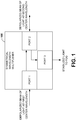
- FIG. 1 illustrates an example apparatus that includes a symmetrical wavelength multiplexor 100 to provide a stabilized light source to a fiber optic gyroscope.
- the symmetrical wavelength multiplexor (SWM) 100 includes a first port (PORT 1) that receives a depolarized beam of light of a first center wavelength for a first wavelength range.
- the first center wavelength can be generated as 1480 nanometers (nm) (or other wavelength) center wavelength over a fairly narrow range of wavelengths of about 2 or 3 nm.
- a second port (PORT 2) of the SWM 100 receives a second center wavelength of light for a second wavelength range that is greater than the first wavelength range.
- the second wavelength can be generated at 1550 nm in one example yet in a broader wavelength range of about 20 nm to 50 nm, for example.
- a third port (PORT 3) of the SWM 100 provides a substantially symmetrical wavelength output to drive a fiber optic gyroscope (FOG) via the second center wavelength.
- the SWM 100 mitigates spectral asymmetries between wavelengths over the second wavelength range.
- spectral asymmetry refers to errors that occur between wavelengths that are generated over the second wavelength range described herein. This can include amplitude and/or phase errors between the different wavelengths within the second range.
- the SWM 100 can be an optical circulator having a first port, second port, and third port, wherein the depolarized beam of light of the first center wavelength travels from the first port to the second port of the optical circulator and light of the second center wavelength travels from the second port to the third port of the optical circulator.
- the SWM 100 can be a wavelength divisions isolator hybrid (WDIH) having a first port, a second port, and a third port, wherein the depolarized beam of light of the first center wavelength travels from the first port to the second port of the WDIH and light of the second center wavelength travels from the second port to the third port of the WDIH. Examples of the optical circulator and WDIH are shown in FIGS. 3 and 4 , respectively.
- FIG. 2 illustrates an example system 200 to provide a stabilized light source to a fiber optic gyroscope.
- An SWM 210 is provided having ports labeled 1, 2, and 3 as previously described herein.
- a light source 214 can be provided for producing a beam of light of the first center wavelength (e.g., 1480 nm) for the first wavelength range (e.g., +/- 2 nm).
- the light source 214 can include a laser diode module (LDM) 216.
- LDM laser diode module
- a fiber optic grating 220 e.g., Bragg Grating
- An optical converter 240 receives the depolarized beam of light of the first center wavelength via port 2 of the SVM 210 to convert the depolarized beam of light into a second center wavelength for the second wavelength range that is greater than the first wavelength range.
- the optical converter 240 can be terminated via fiber cleave 250.
- the optical converter 240 can be implemented as a single mode fiber.
- the optical converter can include an erbium doped fiber (EDF) or an yttrium doped fiber (YDF) to convert the depolarized beam of light into a second center wavelength for the second wavelength range that is greater than the first wavelength range.
- An optical coupler 260 (e.g., 1x3 coupler) can be provided that is driven by the third port of the SVM 210 to generate sensor signals shown as X, Y and Z gyro signals, to drive a fiber optic gyroscope (FOG).
- FOG fiber optic gyroscope
- separate Lyot depolarizers 1, 2 and 3 respectively can be provided to condition the sensor signals to drive the FOG which can b implemented as a multifunction integrated optic chip (MIOC) connected to a fiber optic sensing coil in an example.
- the Lyot depolarizers 1, 2 and 3 can be eliminated with the FOG being driven directly via the coupler 260.
- FIG. 3 illustrates an example system 300 utilizing an optical circulator as a symmetrical wavelength multiplexor to provide a stabilized light source.
- the SWM is an optical circulator 310 having a first port (1), second port (2), and third port (3).
- the depolarized beam of light of the first center wavelength described herein travels from the first port to the second port of the optical circulator 310 and light of the second center wavelength travels from the second port to the third port of the optical circulator.
- FIG. 4 illustrates an example system utilizing a wavelength divisions isolator hybrid (WDIH) as a symmetrical wavelength multiplexor to provide a stabilized light source.
- the SWM is a wavelength divisions isolator hybrid (WDIH) 410 having a first port (1), a second port (2), and a third port (3).
- the depolarized beam of light of the first center wavelength described herein travels from the first port to the second port of the WDIH 410 and light of the second center wavelength travels from the second port to the third port of the WDIH.
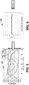
- FIG. 5 illustrates a performance diagram 500 illustrating wavelength asymmetry performance of a wavelength division multiplexor (WDM).
- WDM wavelength division multiplexor
- the X axis indicates a paddle angle of a polarization loop controller in degrees and the Y axis illustrates wavelength deviations in nanometers.
- Output from the WDM was fed through a polarizer which was analyzed by a spectrum analyzer to produce the diagram 500.
- spectral asymmetry refers to errors that occur between wavelengths that are generated over the second wavelength range described herein.
- Wavelength asymmetry is an inherent feature of a wavelength division multiplexor (WDM) that utilizes a fused taper fiber construction that produces the 0.32 nanometer deviation depicted in the diagram 500.
- WDM wavelength division multiplexor
- FIG. 6 illustrates a performance diagram 600 illustrating wavelength symmetry performance of an optical circulator employed as a symmetrical wavelength multiplexor (SWM). Similar to FIG. 5 , the X axis indicates a paddle angle in degrees and the Y axis illustrates wavelength deviations in nanometers.
- output from the SWM was fed through a polarizer which was analyzed by a spectrum analyzer to produce the diagram 600. As shown, there is about 0.03 nanometer of deviation in the waveform output due to the Faraday rotator construction of the SWM (e.g., optical circulator) providing spectral symmetry at the output of the SWM which is in stark contrast to the fused taper performance of the WDM depicted in FIG. 5 .
- the SWM's described herein can include bulk optics trains, birefringent wedges, magnets, and/or thin-filmed mirrors to generate a substantially symmetrical wavelength output from the SWM.
- FIG. 7 illustrates an example method 700 to provide a stabilized light source to a fiber optic gyroscope.
- the method includes receiving a depolarized beam of light of a first center wavelength for a first wavelength range at a first port of a symmetrical wavelength multiplexor (SWM) (e.g., via PORT 1 of SVM 100 of FIG. 1 ).
- the method 700 includes receiving a second center wavelength of light for a second wavelength range that is greater than the first wavelength range at a second port of the SWM (e.g., via PORT 2 of SVM 100 of FIG. 1 ).
- SWM symmetrical wavelength multiplexor
- the method 700 includes generating a substantially symmetrical wavelength output (SWO) at a third port of the SWM in response to receiving the second center wavelength of light for the second wavelength range from the second port of the SWM (e.g., via PORT 3 of SVM 100 of FIG. 1 ).
- the method 700 includes sourcing a fiber optic gyroscope (FOG) via the SWO (e.g., via PORT 1 of SVM 100 of FIG. 1 ).
- FOG fiber optic gyroscope
- the SWM mitigates spectral asymmetries of the SWO between orthogonal axes over the second wavelength range.
- the SWM can be an optical circulator having a first port, second port, and third port, wherein the depolarized beam of light of the first center wavelength travels from the first port to the second port of the optical circulator and light of the second center wavelength travels from the second port to the third port of the optical circulator.
- the SWM can be a wavelength divisions isolator hybrid (WDIH) having a first port, a second port, and a third port, wherein the depolarized beam of light of the first center wavelength travels from the first port to the second port of the WDIH and light of the second center wavelength travels from the second port to the third port of the WDIH.
- WDIH wavelength divisions isolator hybrid
Landscapes
- Physics & Mathematics (AREA)
- Engineering & Computer Science (AREA)
- Optics & Photonics (AREA)
- General Physics & Mathematics (AREA)
- Electromagnetism (AREA)
- Power Engineering (AREA)
- Radar, Positioning & Navigation (AREA)
- Remote Sensing (AREA)
- Lasers (AREA)
- Gyroscopes (AREA)
- Optical Couplings Of Light Guides (AREA)
Applications Claiming Priority (1)
| Application Number | Priority Date | Filing Date | Title |
|---|---|---|---|
| US15/952,355 US10337867B1 (en) | 2018-04-13 | 2018-04-13 | Symmetrical wavelength multiplexor for fiber optic gyro source |
Publications (1)
| Publication Number | Publication Date |
|---|---|
| EP3553469A1 true EP3553469A1 (fr) | 2019-10-16 |
Family
ID=65724212
Family Applications (1)
| Application Number | Title | Priority Date | Filing Date |
|---|---|---|---|
| EP19161150.8A Withdrawn EP3553469A1 (fr) | 2018-04-13 | 2019-03-06 | Multiplexeur de longueur d'onde symétrique pour source de gyroscope à fibres optiques |
Country Status (3)
| Country | Link |
|---|---|
| US (1) | US10337867B1 (fr) |
| EP (1) | EP3553469A1 (fr) |
| JP (1) | JP6744942B2 (fr) |
Cited By (1)
| Publication number | Priority date | Publication date | Assignee | Title |
|---|---|---|---|---|
| EP4080163A4 (fr) * | 2019-12-20 | 2024-04-10 | Tokyo Institute of Technology | Dispositif de source de lumière pour gyroscope à fibre optique et gyroscope à fibre optique l'utilisant |
Families Citing this family (2)
| Publication number | Priority date | Publication date | Assignee | Title |
|---|---|---|---|---|
| US20260009644A1 (en) | 2022-10-07 | 2026-01-08 | Institute Of Science Tokyo | Phase modulation signal generating device for fiber-optic gyroscope |
| US12613437B2 (en) * | 2023-02-06 | 2026-04-28 | Northrop Grumman Systems Corporation | Optical isolator system |
Citations (3)
| Publication number | Priority date | Publication date | Assignee | Title |
|---|---|---|---|---|
| US5949930A (en) * | 1997-07-23 | 1999-09-07 | Litton Systems, Inc. | Apparatus and method for scale factor stabilization in interferometric fiber optic rotation sensors |
| US20030091321A1 (en) * | 2001-11-14 | 2003-05-15 | Honeywell International Inc. | Radiation insensitive fiber light source for interferometric fiber optic gyroscopes (IFOGS) |
| US20040196544A1 (en) * | 2002-12-20 | 2004-10-07 | Rosolem Joao Batista | Double pass optical amplifier with unidirectional compensation of chromatic dispersion and obstruction of backscattering |
Family Cites Families (6)
| Publication number | Priority date | Publication date | Assignee | Title |
|---|---|---|---|---|
| US5311603A (en) * | 1992-10-28 | 1994-05-10 | Litton Systems Inc. | Highly efficient superfluorescent fiber laser/amplifier for interferometric sensors |
| DE69620414T2 (de) | 1995-08-04 | 2002-11-14 | Alcatel, Paris | Optischer einfügungs- und abtrennmultiplexer |
| JPH10112700A (ja) | 1996-10-04 | 1998-04-28 | Nec Corp | リング構成の波長分割多重光伝送装置 |
| US6144788A (en) * | 1998-06-30 | 2000-11-07 | Honeywell, Inc. | High stability fiber light source |
| US7515271B2 (en) * | 2006-04-03 | 2009-04-07 | Honeywell International Inc. | Wavelength calibration in a fiber optic gyroscope |
| US7746476B2 (en) | 2007-07-11 | 2010-06-29 | Emcore Corporation | Fiber optic gyroscope |
-
2018
- 2018-04-13 US US15/952,355 patent/US10337867B1/en active Active
-
2019
- 2019-03-06 EP EP19161150.8A patent/EP3553469A1/fr not_active Withdrawn
- 2019-03-29 JP JP2019065868A patent/JP6744942B2/ja active Active
Patent Citations (3)
| Publication number | Priority date | Publication date | Assignee | Title |
|---|---|---|---|---|
| US5949930A (en) * | 1997-07-23 | 1999-09-07 | Litton Systems, Inc. | Apparatus and method for scale factor stabilization in interferometric fiber optic rotation sensors |
| US20030091321A1 (en) * | 2001-11-14 | 2003-05-15 | Honeywell International Inc. | Radiation insensitive fiber light source for interferometric fiber optic gyroscopes (IFOGS) |
| US20040196544A1 (en) * | 2002-12-20 | 2004-10-07 | Rosolem Joao Batista | Double pass optical amplifier with unidirectional compensation of chromatic dispersion and obstruction of backscattering |
Cited By (1)
| Publication number | Priority date | Publication date | Assignee | Title |
|---|---|---|---|---|
| EP4080163A4 (fr) * | 2019-12-20 | 2024-04-10 | Tokyo Institute of Technology | Dispositif de source de lumière pour gyroscope à fibre optique et gyroscope à fibre optique l'utilisant |
Also Published As
| Publication number | Publication date |
|---|---|
| US10337867B1 (en) | 2019-07-02 |
| JP2019184599A (ja) | 2019-10-24 |
| JP6744942B2 (ja) | 2020-08-19 |
Similar Documents
| Publication | Publication Date | Title |
|---|---|---|
| Ma et al. | Reduction of polarization-fluctuation induced drift in resonator fiber optic gyro by a resonator integrating in-line polarizers | |
| US10180325B2 (en) | Orthogonal-mode laser gyroscope | |
| EP3051257B1 (fr) | Procédé de détection vitesse angulaire mettant en oeuvre un oscillateur optoélectronique de couplage totalement réciproque bidirectionnel | |
| US9733084B2 (en) | Single pump cascaded stimulated Brillouin scattering (SBS) ring laser gyro | |
| US20160313417A1 (en) | Magnetic Field Measuring Apparatus | |
| EP3048420A1 (fr) | Systèmes et procédés pour gyroscope à diffusion brillouin stimulée avec peigne de fréquence optique à résonateur de guide d'ondes optiques rigide | |
| US20140152994A1 (en) | Optical frequency comb stimulated brillouin scattering gyroscope | |
| JP2002519868A (ja) | 高安定性の光源 | |
| EP3553469A1 (fr) | Multiplexeur de longueur d'onde symétrique pour source de gyroscope à fibres optiques | |
| US20150098089A1 (en) | Optical passive resonator gyro with three beams | |
| EP2988096A1 (fr) | Gyroscope à fibre optique résonante avec un coupleur de guide d'ondes à cristaux de polarisation | |
| JP2014063990A (ja) | 往復損失が小さく、かつ、出力パワーが大きいファイバ共振器ジャイロスコープ | |
| US9031366B2 (en) | Stabilized pump laser output system and method | |
| Li et al. | Excess relative intensity noise suppression in depolarized interferometric fiber optic gyroscopes | |
| US9170108B1 (en) | Controlled modulation of light beam with highly stable suppression of carrier or sidebands | |
| US11378401B2 (en) | Polarization-maintaining fully-reciprocal bi-directional optical carrier microwave resonance system and angular velocity measurement method thereof | |
| US9634769B2 (en) | Coolerless fiber light source devices for harsh environments | |
| Wagener et al. | A high-stability fiber amplifier source for the fiber optic gyroscope | |
| EP3015820B1 (fr) | Source lumineuse à fibre à large bande compensée à longueur d'onde moyenne stable pour gyroscope à fibre optique | |
| Ezekiel | Optical gyroscope options: principles and challenges | |
| CN212254118U (zh) | 刻度因数稳定的高精度光纤陀螺仪 | |
| CN111721277A (zh) | 刻度因数稳定的高精度光纤陀螺仪 | |
| Wheeler et al. | A fiber optic gyroscope driven by a low-coherence laser suitable for aircraft navigation | |
| US12449258B2 (en) | Broadband resonator optical gyroscope with efficient optical power management for low shot noise | |
| KR100996707B1 (ko) | 광섬유를 이용한 신호광 발생 장치 및 회전 감지 장치 |
Legal Events
| Date | Code | Title | Description |
|---|---|---|---|
| PUAI | Public reference made under article 153(3) epc to a published international application that has entered the european phase |
Free format text: ORIGINAL CODE: 0009012 |
|
| STAA | Information on the status of an ep patent application or granted ep patent |
Free format text: STATUS: REQUEST FOR EXAMINATION WAS MADE |
|
| 17P | Request for examination filed |
Effective date: 20190306 |
|
| AK | Designated contracting states |
Kind code of ref document: A1 Designated state(s): AL AT BE BG CH CY CZ DE DK EE ES FI FR GB GR HR HU IE IS IT LI LT LU LV MC MK MT NL NO PL PT RO RS SE SI SK SM TR |
|
| AX | Request for extension of the european patent |
Extension state: BA ME |
|
| STAA | Information on the status of an ep patent application or granted ep patent |
Free format text: STATUS: EXAMINATION IS IN PROGRESS |
|
| 17Q | First examination report despatched |
Effective date: 20201217 |
|
| STAA | Information on the status of an ep patent application or granted ep patent |
Free format text: STATUS: THE APPLICATION HAS BEEN WITHDRAWN |
|
| 18W | Application withdrawn |
Effective date: 20210323 |