EP3553562A1 - Sécurité fonctionnelle pour une caméra d'intérieur tridimensionnelle - Google Patents
Sécurité fonctionnelle pour une caméra d'intérieur tridimensionnelle Download PDFInfo
- Publication number
- EP3553562A1 EP3553562A1 EP19159549.5A EP19159549A EP3553562A1 EP 3553562 A1 EP3553562 A1 EP 3553562A1 EP 19159549 A EP19159549 A EP 19159549A EP 3553562 A1 EP3553562 A1 EP 3553562A1
- Authority
- EP
- European Patent Office
- Prior art keywords
- objects
- distance information
- imaging sensor
- signals
- distance
- Prior art date
- Legal status (The legal status is an assumption and is not a legal conclusion. Google has not performed a legal analysis and makes no representation as to the accuracy of the status listed.)
- Withdrawn
Links
- 238000003384 imaging method Methods 0.000 claims abstract description 115
- 238000005259 measurement Methods 0.000 claims abstract description 58
- 238000001514 detection method Methods 0.000 claims abstract description 31
- 230000005855 radiation Effects 0.000 claims abstract description 31
- 238000011156 evaluation Methods 0.000 claims abstract description 29
- 238000000034 method Methods 0.000 claims abstract description 26
- 230000003287 optical effect Effects 0.000 claims description 17
- 230000006870 function Effects 0.000 description 19
- 238000005286 illumination Methods 0.000 description 5
- 238000004590 computer program Methods 0.000 description 3
- 230000004913 activation Effects 0.000 description 2
- 230000008901 benefit Effects 0.000 description 2
- 230000008859 change Effects 0.000 description 2
- 230000002123 temporal effect Effects 0.000 description 2
- 230000015556 catabolic process Effects 0.000 description 1
- 230000001419 dependent effect Effects 0.000 description 1
- 238000011161 development Methods 0.000 description 1
- 230000007613 environmental effect Effects 0.000 description 1
- 230000004927 fusion Effects 0.000 description 1
- 230000007257 malfunction Effects 0.000 description 1
- 230000008569 process Effects 0.000 description 1
- 238000012545 processing Methods 0.000 description 1
- 230000004044 response Effects 0.000 description 1
- 208000037974 severe injury Diseases 0.000 description 1
- 230000009528 severe injury Effects 0.000 description 1
- 230000004083 survival effect Effects 0.000 description 1
- 230000007704 transition Effects 0.000 description 1
- 230000001960 triggered effect Effects 0.000 description 1
Images

Classifications
-
- G—PHYSICS
- G01—MEASURING; TESTING
- G01S—RADIO DIRECTION-FINDING; RADIO NAVIGATION; DETERMINING DISTANCE OR VELOCITY BY USE OF RADIO WAVES; LOCATING OR PRESENCE-DETECTING BY USE OF THE REFLECTION OR RERADIATION OF RADIO WAVES; ANALOGOUS ARRANGEMENTS USING OTHER WAVES
- G01S13/00—Systems using the reflection or reradiation of radio waves, e.g. radar systems; Analogous systems using reflection or reradiation of waves whose nature or wavelength is irrelevant or unspecified
- G01S13/02—Systems using reflection of radio waves, e.g. primary radar systems; Analogous systems
- G01S13/06—Systems determining position data of a target
- G01S13/08—Systems for measuring distance only
-
- G—PHYSICS
- G01—MEASURING; TESTING
- G01S—RADIO DIRECTION-FINDING; RADIO NAVIGATION; DETERMINING DISTANCE OR VELOCITY BY USE OF RADIO WAVES; LOCATING OR PRESENCE-DETECTING BY USE OF THE REFLECTION OR RERADIATION OF RADIO WAVES; ANALOGOUS ARRANGEMENTS USING OTHER WAVES
- G01S17/00—Systems using the reflection or reradiation of electromagnetic waves other than radio waves, e.g. lidar systems
- G01S17/02—Systems using the reflection of electromagnetic waves other than radio waves
- G01S17/06—Systems determining position data of a target
- G01S17/08—Systems determining position data of a target for measuring distance only
- G01S17/10—Systems determining position data of a target for measuring distance only using transmission of interrupted, pulse-modulated waves
-
- B—PERFORMING OPERATIONS; TRANSPORTING
- B60—VEHICLES IN GENERAL
- B60R—VEHICLES, VEHICLE FITTINGS, OR VEHICLE PARTS, NOT OTHERWISE PROVIDED FOR
- B60R1/00—Optical viewing arrangements; Real-time viewing arrangements for drivers or passengers using optical image capturing systems, e.g. cameras or video systems specially adapted for use in or on vehicles
- B60R1/20—Real-time viewing arrangements for drivers or passengers using optical image capturing systems, e.g. cameras or video systems specially adapted for use in or on vehicles
- B60R1/29—Real-time viewing arrangements for drivers or passengers using optical image capturing systems, e.g. cameras or video systems specially adapted for use in or on vehicles for viewing an area inside the vehicle, e.g. for viewing passengers or cargo
-
- G—PHYSICS
- G01—MEASURING; TESTING
- G01S—RADIO DIRECTION-FINDING; RADIO NAVIGATION; DETERMINING DISTANCE OR VELOCITY BY USE OF RADIO WAVES; LOCATING OR PRESENCE-DETECTING BY USE OF THE REFLECTION OR RERADIATION OF RADIO WAVES; ANALOGOUS ARRANGEMENTS USING OTHER WAVES
- G01S17/00—Systems using the reflection or reradiation of electromagnetic waves other than radio waves, e.g. lidar systems
- G01S17/02—Systems using the reflection of electromagnetic waves other than radio waves
- G01S17/06—Systems determining position data of a target
- G01S17/08—Systems determining position data of a target for measuring distance only
-
- G—PHYSICS
- G01—MEASURING; TESTING
- G01S—RADIO DIRECTION-FINDING; RADIO NAVIGATION; DETERMINING DISTANCE OR VELOCITY BY USE OF RADIO WAVES; LOCATING OR PRESENCE-DETECTING BY USE OF THE REFLECTION OR RERADIATION OF RADIO WAVES; ANALOGOUS ARRANGEMENTS USING OTHER WAVES
- G01S17/00—Systems using the reflection or reradiation of electromagnetic waves other than radio waves, e.g. lidar systems
- G01S17/02—Systems using the reflection of electromagnetic waves other than radio waves
- G01S17/06—Systems determining position data of a target
- G01S17/42—Simultaneous measurement of distance and other co-ordinates
-
- G—PHYSICS
- G01—MEASURING; TESTING
- G01S—RADIO DIRECTION-FINDING; RADIO NAVIGATION; DETERMINING DISTANCE OR VELOCITY BY USE OF RADIO WAVES; LOCATING OR PRESENCE-DETECTING BY USE OF THE REFLECTION OR RERADIATION OF RADIO WAVES; ANALOGOUS ARRANGEMENTS USING OTHER WAVES
- G01S17/00—Systems using the reflection or reradiation of electromagnetic waves other than radio waves, e.g. lidar systems
- G01S17/02—Systems using the reflection of electromagnetic waves other than radio waves
- G01S17/06—Systems determining position data of a target
- G01S17/46—Indirect determination of position data
-
- G—PHYSICS
- G01—MEASURING; TESTING
- G01S—RADIO DIRECTION-FINDING; RADIO NAVIGATION; DETERMINING DISTANCE OR VELOCITY BY USE OF RADIO WAVES; LOCATING OR PRESENCE-DETECTING BY USE OF THE REFLECTION OR RERADIATION OF RADIO WAVES; ANALOGOUS ARRANGEMENTS USING OTHER WAVES
- G01S17/00—Systems using the reflection or reradiation of electromagnetic waves other than radio waves, e.g. lidar systems
- G01S17/86—Combinations of lidar systems with systems other than lidar, radar or sonar, e.g. with direction finders
-
- G—PHYSICS
- G01—MEASURING; TESTING
- G01S—RADIO DIRECTION-FINDING; RADIO NAVIGATION; DETERMINING DISTANCE OR VELOCITY BY USE OF RADIO WAVES; LOCATING OR PRESENCE-DETECTING BY USE OF THE REFLECTION OR RERADIATION OF RADIO WAVES; ANALOGOUS ARRANGEMENTS USING OTHER WAVES
- G01S17/00—Systems using the reflection or reradiation of electromagnetic waves other than radio waves, e.g. lidar systems
- G01S17/88—Lidar systems specially adapted for specific applications
- G01S17/89—Lidar systems specially adapted for specific applications for mapping or imaging
-
- G—PHYSICS
- G01—MEASURING; TESTING
- G01S—RADIO DIRECTION-FINDING; RADIO NAVIGATION; DETERMINING DISTANCE OR VELOCITY BY USE OF RADIO WAVES; LOCATING OR PRESENCE-DETECTING BY USE OF THE REFLECTION OR RERADIATION OF RADIO WAVES; ANALOGOUS ARRANGEMENTS USING OTHER WAVES
- G01S7/00—Details of systems according to groups G01S13/00, G01S15/00, G01S17/00
- G01S7/48—Details of systems according to groups G01S13/00, G01S15/00, G01S17/00 of systems according to group G01S17/00
- G01S7/497—Means for monitoring or calibrating
-
- H—ELECTRICITY
- H04—ELECTRIC COMMUNICATION TECHNIQUE
- H04N—PICTORIAL COMMUNICATION, e.g. TELEVISION
- H04N13/00—Stereoscopic video systems; Multi-view video systems; Details thereof
- H04N13/20—Image signal generators
- H04N13/257—Colour aspects
-
- H—ELECTRICITY
- H04—ELECTRIC COMMUNICATION TECHNIQUE
- H04N—PICTORIAL COMMUNICATION, e.g. TELEVISION
- H04N23/00—Cameras or camera modules comprising electronic image sensors; Control thereof
- H04N23/50—Constructional details
- H04N23/54—Mounting of pick-up tubes, electronic image sensors, deviation or focusing coils
-
- H—ELECTRICITY
- H04—ELECTRIC COMMUNICATION TECHNIQUE
- H04N—PICTORIAL COMMUNICATION, e.g. TELEVISION
- H04N23/00—Cameras or camera modules comprising electronic image sensors; Control thereof
- H04N23/56—Cameras or camera modules comprising electronic image sensors; Control thereof provided with illuminating means
-
- B—PERFORMING OPERATIONS; TRANSPORTING
- B60—VEHICLES IN GENERAL
- B60R—VEHICLES, VEHICLE FITTINGS, OR VEHICLE PARTS, NOT OTHERWISE PROVIDED FOR
- B60R11/00—Arrangements for holding or mounting articles, not otherwise provided for
- B60R11/04—Mounting of cameras operative during drive; Arrangement of controls thereof relative to the vehicle
-
- B—PERFORMING OPERATIONS; TRANSPORTING
- B60—VEHICLES IN GENERAL
- B60R—VEHICLES, VEHICLE FITTINGS, OR VEHICLE PARTS, NOT OTHERWISE PROVIDED FOR
- B60R11/00—Arrangements for holding or mounting articles, not otherwise provided for
- B60R2011/0001—Arrangements for holding or mounting articles, not otherwise provided for characterised by position
- B60R2011/0003—Arrangements for holding or mounting articles, not otherwise provided for characterised by position inside the vehicle
Definitions
- the invention relates to an imaging sensor for a land vehicle for obtaining distance information according to claim 1. Furthermore, the invention relates to an imaging system for a land vehicle for obtaining distance information according to claim 6. Furthermore, the invention relates to a use of an imaging system according to the invention in an environment detection system of a land vehicle according to claim 10 Furthermore, the invention relates to an environment detection system for a land vehicle according to claim 11. Finally, the invention relates to a method for the functional protection of an environment detection system of a land vehicle according to claim 13.
- Interior cameras for land vehicles are known from the prior art. Such indoor cameras provide a two- or three-dimensional image and / or a temporal sequence of such images of the vehicle interior. In particular, indoor cameras provide such images and / or sequences of images of persons located in the interior of the land vehicle, in particular by a vehicle driver, a passenger and / or another passenger.
- One known type of indoor camera is so-called time-of-flight cameras, which calculate a distance of the object to the camera based on a light transit time between the camera and an object.
- the WO 2014/195020 A1 discloses an imaging system having a time-of-flight imaging sensor, wherein the system is configured to obtain an image of a scene, wherein the scene has been illuminated with at least two different illumination sources.
- the invention has for its object to provide an interior camera for a land vehicle with improved functional safety.
- the object is solved with an imaging sensor for a land vehicle for obtaining distance information with the features of claim 1. Furthermore, the object is achieved with an imaging system for a land vehicle for obtaining distance information with the features of claim 6. Further, the object is achieved by a The use of an imaging system according to the invention as claimed in claim 10. Furthermore, the object is achieved with an environment detection system for a land vehicle having the features of claim 11. In addition, the object is achieved by a method for the functional safety of an environment detection system of a land vehicle having the features of claim 13.
- the land vehicle imaging sensor for obtaining distance information is configured to detect first and second signals.
- the first signals are beam pulses reflected at objects illuminated with beam pulses of a first radiator.
- the second signals are beam patterns reflected at the objects illuminated with beam patterns of a second radiator.
- the imaging sensor has an evaluation device.
- the evaluation device is designed to obtain a first distance information of these objects as a function of the first signals in a first distance measurement.
- the evaluation device is designed to obtain a second distance information of these objects as a function of the second signals in a second distance measurement.
- the evaluation device is designed to obtain a third distance information of these objects as a function of a comparison of the first and the second distance information.
- the imaging sensor has an output interface that is designed to provide an image of these objects in dependence on the third distance information.
- the imaging sensor is designed such that it is functionally secured by the first and the second distance measurement in case of failure of one of these distance measurements.
- An imaging sensor is a sensor that generates an image from incoming signals, preferably incident light.
- An imaging sensor of a digital camera generates a two-dimensional image of the recorded scene from the light incident on the sensor.
- a radiator is a device that provides rays, for example light, preferably in the form of bundles of rays.
- a beam is a number of beams, the beams being aligned with each other, preferably approximately parallel to one another.
- the spotlight illuminates objects with the beams.
- a projector is a spotlight.
- a radiation pulse is a beam that exists in a finite time period. This period may be repeated, preferably periodically. Depending on a particular application, the time periods range from the order of nanoseconds to the order of attoseconds.
- a time-coded signal having a temporal pulse train is a beam pulse.
- a ray pattern is a geometric shape of the illumination that is achieved with these rays by a corresponding radiator that produces these patterns. Patterns are for example geometric shapes such as lines or circles. Pattern also means a sequence of such shapes. The patterns are achieved by space coding of signals. An illumination with radiation patterns is referred to in English as structured lighting.
- beams are used in particular light beams in the infrared wavelength range.
- An evaluation device is a device that processes incoming information and outputs a result resulting from this processing.
- an evaluation device is an electronic circuit, such as a central processor unit or a graphics processor.
- the first distance measurement is a transit time measurement.
- the evaluation device detects the time required for the radiation pulse to reach the object from the first radiator and to reach the evaluation device from the object as a reflected radiation pulse. Based on this transit time, the distance of the object to the evaluation device results, knowing the propagation velocity of the radiation pulse.
- the second distance measurement is a geometric measurement and preferably redundant to the first distance measurement.
- the evaluation device detects a geometric change of the beam pattern reflected on an object in comparison to the beam pattern transmitted with the second radiator.
- patterns of reflected beam patterns appear distorted compared to patterns of transmitted beam patterns.
- points of a transmitted dot pattern appear distorted on a distant curved surface as compared to a near planar surface. That is, depending on this geometric change, the distance to the object is determined.
- An interface is a device between at least two functional units, at which an exchange of logical quantities, for example data, or physical quantities, for example electrical signals, takes place, either only unidirectionally or bidirectionally.
- the exchange can be analog or digital.
- the exchange can be wireless or wired.
- the image provided by the output interface is a three-dimensional image in which the objects are displayed in three dimensions.
- the distance of individual object points is preferably represented as a function of gray levels.
- a component of a system performs a safety-related function correctly.
- Functional safety means that the system is safely controlled in the event of a component failure, in particular either by transition to a predefined safe state or by activation of another component which takes over the function of the failed component.
- Systems with functional safety have a low probability of failure.
- different levels of safety are distinguished according to the standard ISO 26262, which differ according to a recommended or required failure probability. These levels are called ASIL, in English Automotive Safety Integrity Level, stages.
- ASIL A recommends that fewer than 1000 failures occur within 10 9 hours of operation.
- ASIL B recommends that less than 100 failures occur within 10 9 hours of operation.
- ASIL C claims that fewer than 100 outages occur within 10 9 hours of operation.
- ASIL D claims that fewer than 10 failures occur within 10 9 hours of operation.
- the malfunction can occur constantly, that is, has a high probability of occurrence, for example when accelerating, braking or steering, and difficult to control, ASIL D demanded.
- the third distance information is equal to the first one of the second distance information. If an error has occurred in the first distance information, that is, a result of the first distance measurement is zero and a result of the second distance measurement is different from zero, then the third distance information is equal to the second distance information. If an error has occurred in the second distance measurement, that is, if the result of the second distance information is 0 and the result of the first distance information is different from 0, then the third distance information is equal to the first distance information. Due to this redundancy in the distance measurement, the imaging sensor is functionally secured. In addition, a result of the first distance measurement may be compared with a result of the second distance measurement to increase the accuracy of the result.
- the imaging sensor is a transit time method sensor, referred to in English as a time-of-flight sensor.
- a time-of-flight sensor each pixel of the sensor collects incident light and at the same time measures the time the light takes to travel from a source to the object and get back to the pixel from the object.
- Each of the pixels of the time-of-flight sensors converts light into an electric current.
- the pixel operates with a plurality of switches and a respective memory element associated with a switch. In the simplest case, each pixel has two switches and two memory elements. The switches are driven with emission of the beam pulse and for the period of the beam pulse, that is, the pulse length opened.
- the control signals of the respective switches are each temporally shifted by one pulse length.
- a reflected beam pulse is applied to the pixel with a delay, only part of the beam pulse reaches the first memory element, the other part is collected in the second memory element. Depending on the distance, this changes the ratio of collected light in the first to collected light in the second storage element.
- a distance measurement with light of a lighting source is obtained.
- the light of the second illumination source is used there only to improve the resolution.
- the advantage of the imaging sensor according to the invention is that with an imaging sensor two independent distance measurements are carried out and, based on these distance measurements, even if a distance measurement fails, a resulting distance measurement is always obtained. This means that the imaging sensor is functionally protected against failure of one of the distance measurements.
- the evaluation device is designed to obtain color image data of these objects and to obtain a three-dimensional color image of these objects as a function of this color image data and the third distance information, wherein the output interface is designed to provide this color image.
- This provides, in particular, a time-of-flight sensor which delivers a three-dimensional color image with distance information.
- two-dimensional image data of a conventional two-dimensional image sensor can be used with the two-dimensional data of the imaging sensor according to the invention are adjusted to increase the functional safety of the imaging sensor.
- the evaluation device is designed to perform a comparison of the first and / or second signals with the color image data. This comparison improves functional safety.
- the imaging sensor is an imaging sensor of an interior camera of the land vehicle and / or the output interface is a human-machine interface, referred to in English as a human machine interface, preferably in the form of a screen of an infotainment system of the land vehicle.
- a human-machine interface referred to in English as a human machine interface, preferably in the form of a screen of an infotainment system of the land vehicle.
- the imaging system for a land vehicle according to the invention for obtaining distance information has a first radiator.
- the first radiator is designed to illuminate objects with radiation pulses.
- the imaging system also includes a second radiator.
- the second radiator is designed to illuminate the objects with beam patterns.
- the imaging system has an imaging sensor.
- the imaging sensor is configured to detect first and second signals.
- the first signals are reflected by the radiation pulses illuminated by the radiation pulses.
- the second signals are beam patterns reflected at the objects illuminated with the beam patterns.
- the imaging system has an evaluation device.
- the evaluation device is designed to obtain a first distance information of the objects as a function of the first signals in a first distance measurement.
- the evaluation device is designed to obtain a second distance information of the objects as a function of the second signals in a second distance measurement. Furthermore, the evaluation device is designed to obtain a third distance information of the objects as a function of a comparison of the first and the second distance measurement.
- the imaging system has an output interface. The output interface is designed to provide an image of these objects in dependence on the third distance information. The imaging system is designed such that it is functionally secured by the first and the second distance measurement in case of failure of one of these distance measurements.
- the imaging system provides a complete imaging system that has the advantages of the imaging sensor of the present invention.
- the imaging system preferably has an optical device that is designed to image rays reflected on these objects on the imaging sensor.
- An optical device is an optical system that collects reflected rays on a surface of an imaging sensor of the imaging system.
- the optical device preferably has an optical bandpass filter, which transmits only the wavelengths with which the illumination also works. This eliminates much of the disturbing background light.
- disturbing background light is also eliminated by means of the first and the second signals of the imaging sensor.
- the disturbing background light appears both in the first signal and in the second signal and can be easily subtracted.
- the imaging sensor and / or the optical device are functionally protected by the first and the second distance measurement, and / or preferably by a comparison of the first and / or the second signals with color images of these objects.
- a failure rate of the imaging system is less than 100 failures per 10 9 operating hours of the operating system. This achieves an ASIL B level for the imaging system.
- the color images are obtained with the optical device of the imaging system, so that the imaging system has only one optical path, which according to the Invention is functionally secured.
- the color images can also be obtained with a second optical device.
- the imaging sensor is an imaging sensor according to the invention.
- the invention also relates to a use of an imaging system according to the invention in an environment detection system, preferably an interior camera, of a land vehicle.
- An environment detection system is a system that detects the environment of a vehicle and provides the detection for a driver of the land vehicle, in particular in the context of assisting driving tasks or even in an automated driving operation.
- Surrounding detection systems are, for example, outdoor cameras with a corresponding fusion of the collected camera data and a dependent activation of vehicle actuators.
- an imaging sensor of the surroundings detection system is an imaging sensor according to the invention or an imaging system of the surroundings detection system, an imaging system according to the invention.
- the surroundings detection system is an interior camera.
- color images of these objects are obtained, and these color image data are compared with the rays reflected at these objects to enhance the functional safety of the surround detection system.
- an inventive imaging sensor or an imaging system according to the invention is used.
- a computer program product according to the invention is designed to be loaded into a memory of a computer and comprises software code sections with which the method according to the invention can be carried out when the computer program is running in the computer.
- the computer program product is loaded into a memory of the imaging sensor or the imaging system.
- Fig. 1 shows as a land vehicle 1 a car.
- a vehicle occupant In an interior 6 of the land vehicle 1 is arranged on a driver's seat as an object 2, a vehicle occupant.
- the vehicle occupant is, for example, the vehicle driver.
- the vehicle occupant may also be a passenger.
- Vehicle occupants are also passengers, eg children, in the back seat.
- an interior camera 3 is arranged as the surroundings detection system 50.
- the interior camera 3 is designed such that it covers the entire interior space 6.
- the interior camera preferably has a wide-angle objective as an optical device 23.
- the surroundings detection system 50 may be connected to other driver assistance systems and vehicle actuators. In particular, the data collected by the individual driver assistance systems are fused together.
- the interior camera 3 detects the object 2 and an arrangement of a safety belt 5.
- the interior camera 3 is in particular connected to an airbag control.
- the interior camera 3 detects that the vehicle driver is sitting counter to the direction of travel, ie with his face and upper body pointing against the direction of travel to the rear bench, then the interior camera 3 controls the airbag control for the vehicle driver in such a way that an airbag is not triggered , The interior camera 3 switches the airbag control for the vehicle driver into an active state only when the interior camera 3 has detected that the driver is sitting in the direction of travel.
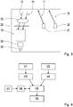
- Fig. 2 1 shows an imaging sensor 10.
- a pixel arrangement 16 of the imaging sensor 10 receives first signals 11 reflected by the object 2 and second signals 12.
- the object 2 is illuminated by radiation pulses 13 from a first radiator 21.
- the object 2 is illuminated with beam patterns 15 of a second radiator 22.
- a single beam pulse of the beam pulses 13 has a duration of preferably less than 50 ns, in particular a duration of 10 ns.
- the beam pattern 15 is an array of light spots.
- the pixel array 16 is a two-dimensional array of pixels.
- the imaging sensor 10 has, for example, a square shape with an edge length of 45 ⁇ m. In this case, the pixel arrangement 16 preferably has 200 ⁇ 200 pixels.
- An evaluation device 30 receives a first distance information of the illuminated object 2 from the signals obtained with the pixel arrangement 16.
- the first distance measurement is a measurement of transit times of the radiation pulses 13.
- distance information of these objects is obtained as a function of the transit times ,
- the evaluation device receives a second distance information of the illuminated object 2.
- the second distance measurement measures reflection patterns of the radiation patterns 15 and obtains a second distance information of the illuminated object as a function of the reflection patterns.
- the signals which the evaluation device 30 receives from the pixel arrangement 16 are fused to signals of a 2D imaging sensor 4.
- the 2D imaging sensor 2 is a high-resolution two-dimensional imaging sensor.
- the evaluation device 30 thus fuses the signals obtained with the pixel array 16 with color image data of the 2D imaging sensor 14 and obtains a high-resolution three-dimensional image with color information. This image is provided via an output interface 40 as a function of the third distance information which the evaluation device 30 receives from a comparison of the first distance information with the second distance information.
- the 2D imaging sensor 14 preferably has the same optical device 23 as the imaging system 20, ie it is arranged in the optical path of the imaging sensor 10. Alternatively, the 2D imaging sensor 14 has its own optical device 23.
- the output interface 40 is a human machine interface in the form of a screen of an infotainment system of the land vehicle.
- Fig. 3 shows an imaging system 20.
- the imaging system 20 includes a first radiator 21 and a second radiator 22.
- the first radiator 21 illuminates objects with first signals 11.
- the first signals 11 are radiation pulses with a specific pulse length.
- the second radiator 22 illuminates objects 2 with beam patterns by means of a second signal 12.
- the imaging system 20 further includes an optic device 23.
- the optical device 23 is a system of optical collecting and / or diverging lenses.
- the imaging system 20 has an evaluation device 30 and an output interface 40.
- the imaging sensor 10 is preferably an imaging sensor 10 according to the invention.
- the output interface 40 provides an image of the object 2 as a function of the third distance information obtained with the evaluation device 30 from a comparison of the first distance information with the second distance information.
- Fig. 4 shows a method for functional protection of an environment detection system 50.
- objects 2 are illuminated in a first method step V1 with radiation pulses 13. There are obtained at the objects 2 reflected radiation pulses 13.
- the objects 2 are illuminated with beam patterns 15. There are obtained at the objects reflected beam pattern 15.
- the process steps V1 and V2 take place successively in time or parallel in time.
- transit times of the radiation pulses are measured, and in a method step V3 a first distance information of the object 2 is obtained as a function of the transit times.
- a second distance measurement will be Reflection pattern of the beam pattern measured and obtained in a step V4 a second distance information of the object 2 in response to the reflection pattern.
- a method step V5 the first and the second distance information are compared with one another and, depending on the comparison, a third distance information of the object 2 is obtained. Depending on the third distance information, an image of the object 2 is provided in method step V6. Parallel to the comparison of the first and the second distance information, color images of the objects 2 are obtained in a method step V7. These color images are compared in a method step V8 with reflected at the objects 2 rays.
- the data of the 2D imaging sensor is compared with the two-dimensional image information of the imaging sensor 10.
- the imaging sensor 10 is preferably a time-of-flight sensor.
Landscapes
- Engineering & Computer Science (AREA)
- Physics & Mathematics (AREA)
- Radar, Positioning & Navigation (AREA)
- Remote Sensing (AREA)
- Electromagnetism (AREA)
- Computer Networks & Wireless Communication (AREA)
- General Physics & Mathematics (AREA)
- Multimedia (AREA)
- Signal Processing (AREA)
- Mechanical Engineering (AREA)
- Optical Radar Systems And Details Thereof (AREA)
- Studio Devices (AREA)
Applications Claiming Priority (1)
| Application Number | Priority Date | Filing Date | Title |
|---|---|---|---|
| DE102018204902.5A DE102018204902A1 (de) | 2018-03-29 | 2018-03-29 | Funktionale Sicherheit für eine dreidimensionale Innenraumkamera |
Publications (1)
| Publication Number | Publication Date |
|---|---|
| EP3553562A1 true EP3553562A1 (fr) | 2019-10-16 |
Family
ID=65628590
Family Applications (1)
| Application Number | Title | Priority Date | Filing Date |
|---|---|---|---|
| EP19159549.5A Withdrawn EP3553562A1 (fr) | 2018-03-29 | 2019-02-27 | Sécurité fonctionnelle pour une caméra d'intérieur tridimensionnelle |
Country Status (4)
| Country | Link |
|---|---|
| US (1) | US10746877B2 (fr) |
| EP (1) | EP3553562A1 (fr) |
| CN (1) | CN110320526A (fr) |
| DE (1) | DE102018204902A1 (fr) |
Citations (3)
| Publication number | Priority date | Publication date | Assignee | Title |
|---|---|---|---|---|
| EP1933167A2 (fr) * | 2006-12-15 | 2008-06-18 | Sick Ag | Capteur optoélectronique et procédé de détection et de détermination des distances d'un objet |
| DE102015010421A1 (de) * | 2015-08-11 | 2017-02-16 | Daimler Ag | Dreidimensionale Erfassung des Fahrzeuginnenraums |
| DE102016110514A1 (de) * | 2016-06-07 | 2017-12-07 | Pilz Gmbh & Co. Kg | Vorrichtung und Verfahren zum Überwachen eines Raumbereichs, insbesondere zum Absichern eines Gefahrenbereichs einer automatisiert arbeitenden Anlage |
Family Cites Families (7)
| Publication number | Priority date | Publication date | Assignee | Title |
|---|---|---|---|---|
| US5646843A (en) * | 1990-02-05 | 1997-07-08 | Caterpillar Inc. | Apparatus and method for surface based vehicle control system |
| EP1031471B1 (fr) * | 1999-02-25 | 2004-12-15 | Siemens Aktiengesellschaft | Procédé ou appareil pour la création d'un image de position utilisant la rayonnement que est réfléchie ou émis par un objet ou une personne |
| US7544945B2 (en) | 2006-02-06 | 2009-06-09 | Avago Technologies General Ip (Singapore) Pte. Ltd. | Vertical cavity surface emitting laser (VCSEL) array laser scanner |
| US8139142B2 (en) * | 2006-06-01 | 2012-03-20 | Microsoft Corporation | Video manipulation of red, green, blue, distance (RGB-Z) data including segmentation, up-sampling, and background substitution techniques |
| DE102007025373B3 (de) * | 2007-05-31 | 2008-07-17 | Sick Ag | Visuelle Überwachung mit Entfernungsbestimmung und Plausibilitätsprüfung anhand von Bildgrößen |
| DE102011082103B4 (de) * | 2011-09-02 | 2017-08-24 | Audi Ag | Sicherheitssystem für ein Kraftfahrzeug |
| US10401498B2 (en) * | 2013-06-06 | 2019-09-03 | Ams Sensors Singapore Pte. Ltd. | Sensor system with active illumination |
-
2018
- 2018-03-29 DE DE102018204902.5A patent/DE102018204902A1/de not_active Ceased
-
2019
- 2019-02-27 EP EP19159549.5A patent/EP3553562A1/fr not_active Withdrawn
- 2019-03-28 CN CN201910241491.1A patent/CN110320526A/zh active Pending
- 2019-03-28 US US16/368,437 patent/US10746877B2/en active Active
Patent Citations (3)
| Publication number | Priority date | Publication date | Assignee | Title |
|---|---|---|---|---|
| EP1933167A2 (fr) * | 2006-12-15 | 2008-06-18 | Sick Ag | Capteur optoélectronique et procédé de détection et de détermination des distances d'un objet |
| DE102015010421A1 (de) * | 2015-08-11 | 2017-02-16 | Daimler Ag | Dreidimensionale Erfassung des Fahrzeuginnenraums |
| DE102016110514A1 (de) * | 2016-06-07 | 2017-12-07 | Pilz Gmbh & Co. Kg | Vorrichtung und Verfahren zum Überwachen eines Raumbereichs, insbesondere zum Absichern eines Gefahrenbereichs einer automatisiert arbeitenden Anlage |
Also Published As
| Publication number | Publication date |
|---|---|
| CN110320526A (zh) | 2019-10-11 |
| US10746877B2 (en) | 2020-08-18 |
| DE102018204902A1 (de) | 2019-10-02 |
| US20190302260A1 (en) | 2019-10-03 |
Similar Documents
| Publication | Publication Date | Title |
|---|---|---|
| EP2569953B1 (fr) | Auto-diagnose optique d'un système de caméras stéréoscopiques | |
| EP0767357B1 (fr) | Dispositif de mesure pour analyser sans contact des objets et des surfaces | |
| EP1759329B1 (fr) | Procede pour calibrer un systeme de capteurs pour la surveillance de l'espace interieur d'un vehicule | |
| EP2150939B1 (fr) | Procédé et dispositif pour déterminer la position d'un panneau de signalisation | |
| DE102018206777A1 (de) | Tiefenauswertung zur Lokalisierung eines Fahrzeuginsassen in einem Fahrzeuginnenraum | |
| EP3188080B1 (fr) | Procédé d'évaluation de gestes | |
| DE112021002044T5 (de) | Anzeigesteuervorrichtung, Anzeigesteuersystem und Anzeigesteuerverfahren | |
| DE102010039092A1 (de) | Verfahren und Steuergerät zum Ermitteln eines Abstandes eines Objektes von einem Fahrzeug | |
| DE102011108292A1 (de) | Verfahren zum Betrieb einer Fahrerassistenzvorrichtung | |
| DE102011075702A1 (de) | Verfahren und Vorrichtung zur Ausrichtung einer Projektion einer Projektionseinrichtung eines Fahrzeugs | |
| WO2016124189A1 (fr) | Système capteur pour véhicule et procédé | |
| DE102020205508A1 (de) | Verfahren und Anordnung zur Registrierung und Bewertung eines Kollisionsereignisses an einem Fahrzeug | |
| DE102012218320A1 (de) | Digitales Rückspiegelsystem | |
| DE102011105074A1 (de) | Verfahren und Vorrichtung zur Bestimmung einer Sichtweite für ein Fahrzeug | |
| DE102020128732A1 (de) | Verfahren und Vorrichtung zum Erkennen von Blooming-Kandidaten in einer Lidarmessung | |
| WO2000065538A1 (fr) | Procede et dispositif pour determiner la position d'un objet dans une situation donnee | |
| EP1575808B1 (fr) | Systeme d'imagerie | |
| DE102014201158A1 (de) | Verfahren und Vorrichtung zum Überprüfen eines von einer Objekterkennung erkannten relevanten Objekts | |
| DE102019201134B4 (de) | Verfahren, Computerprogramm mit Instruktionen und System zum Einmessen einer Augmented-Reality-Brille und Augmented-Reality-Brille zur Verwendung in einem Kraftfahrzeug | |
| DE102020201837A1 (de) | LiDAR-Anordnung, LiDAR-System, Fahrzeug und Verfahren | |
| DE102008001781A1 (de) | Verfahren und Steuergerät zur Ansteuerung von Personenschutzmitteln für ein Fahrzeug | |
| EP3553562A1 (fr) | Sécurité fonctionnelle pour une caméra d'intérieur tridimensionnelle | |
| DE102019211459A1 (de) | Verfahren und Vorrichtung zum Überprüfen einer Kalibrierung von Umfeldsensoren | |
| DE102016215501B4 (de) | Verfahren und Vorrichtung zur Hinderniserkennung durch Landmarken | |
| DE102019127322A1 (de) | Verfahren zur Erfassung von Objekten in einer Fahrzeugumgebung, Vorrichtung zur Datenverarbeitung, Computerprogrammprodukt und computerlesbarer Datenträger |
Legal Events
| Date | Code | Title | Description |
|---|---|---|---|
| PUAI | Public reference made under article 153(3) epc to a published international application that has entered the european phase |
Free format text: ORIGINAL CODE: 0009012 |
|
| STAA | Information on the status of an ep patent application or granted ep patent |
Free format text: STATUS: THE APPLICATION HAS BEEN PUBLISHED |
|
| AK | Designated contracting states |
Kind code of ref document: A1 Designated state(s): AL AT BE BG CH CY CZ DE DK EE ES FI FR GB GR HR HU IE IS IT LI LT LU LV MC MK MT NL NO PL PT RO RS SE SI SK SM TR |
|
| AX | Request for extension of the european patent |
Extension state: BA ME |
|
| STAA | Information on the status of an ep patent application or granted ep patent |
Free format text: STATUS: REQUEST FOR EXAMINATION WAS MADE |
|
| 17P | Request for examination filed |
Effective date: 20200408 |
|
| STAA | Information on the status of an ep patent application or granted ep patent |
Free format text: STATUS: THE APPLICATION IS DEEMED TO BE WITHDRAWN |
|
| 18D | Application deemed to be withdrawn |
Effective date: 20210901 |