EP3553664B1 - Procédé et appareil de calcul de capacité disponible de système de stockage - Google Patents
Procédé et appareil de calcul de capacité disponible de système de stockage Download PDFInfo
- Publication number
- EP3553664B1 EP3553664B1 EP17898328.4A EP17898328A EP3553664B1 EP 3553664 B1 EP3553664 B1 EP 3553664B1 EP 17898328 A EP17898328 A EP 17898328A EP 3553664 B1 EP3553664 B1 EP 3553664B1
- Authority
- EP
- European Patent Office
- Prior art keywords
- storage system
- stripe
- available
- cdg
- disk
- Prior art date
- Legal status (The legal status is an assumption and is not a legal conclusion. Google has not performed a legal analysis and makes no representation as to the accuracy of the status listed.)
- Active
Links
Images


Classifications
-
- G—PHYSICS
- G06—COMPUTING OR CALCULATING; COUNTING
- G06F—ELECTRIC DIGITAL DATA PROCESSING
- G06F3/00—Input arrangements for transferring data to be processed into a form capable of being handled by the computer; Output arrangements for transferring data from processing unit to output unit, e.g. interface arrangements
- G06F3/06—Digital input from, or digital output to, record carriers, e.g. RAID, emulated record carriers or networked record carriers
- G06F3/0601—Interfaces specially adapted for storage systems
- G06F3/0628—Interfaces specially adapted for storage systems making use of a particular technique
- G06F3/0653—Monitoring storage devices or systems
-
- G—PHYSICS
- G06—COMPUTING OR CALCULATING; COUNTING
- G06F—ELECTRIC DIGITAL DATA PROCESSING
- G06F3/00—Input arrangements for transferring data to be processed into a form capable of being handled by the computer; Output arrangements for transferring data from processing unit to output unit, e.g. interface arrangements
- G06F3/06—Digital input from, or digital output to, record carriers, e.g. RAID, emulated record carriers or networked record carriers
- G06F3/0601—Interfaces specially adapted for storage systems
- G06F3/0602—Interfaces specially adapted for storage systems specifically adapted to achieve a particular effect
- G06F3/0604—Improving or facilitating administration, e.g. storage management
- G06F3/0607—Improving or facilitating administration, e.g. storage management by facilitating the process of upgrading existing storage systems, e.g. for improving compatibility between host and storage device
-
- G—PHYSICS
- G06—COMPUTING OR CALCULATING; COUNTING
- G06F—ELECTRIC DIGITAL DATA PROCESSING
- G06F3/00—Input arrangements for transferring data to be processed into a form capable of being handled by the computer; Output arrangements for transferring data from processing unit to output unit, e.g. interface arrangements
- G06F3/06—Digital input from, or digital output to, record carriers, e.g. RAID, emulated record carriers or networked record carriers
- G06F3/0601—Interfaces specially adapted for storage systems
- G06F3/0668—Interfaces specially adapted for storage systems adopting a particular infrastructure
- G06F3/0671—In-line storage system
- G06F3/0683—Plurality of storage devices
- G06F3/0689—Disk arrays, e.g. RAID, JBOD
-
- G—PHYSICS
- G06—COMPUTING OR CALCULATING; COUNTING
- G06F—ELECTRIC DIGITAL DATA PROCESSING
- G06F3/00—Input arrangements for transferring data to be processed into a form capable of being handled by the computer; Output arrangements for transferring data from processing unit to output unit, e.g. interface arrangements
- G06F3/06—Digital input from, or digital output to, record carriers, e.g. RAID, emulated record carriers or networked record carriers
- G06F3/0601—Interfaces specially adapted for storage systems
- G06F3/0602—Interfaces specially adapted for storage systems specifically adapted to achieve a particular effect
- G06F3/0604—Improving or facilitating administration, e.g. storage management
- G06F3/0605—Improving or facilitating administration, e.g. storage management by facilitating the interaction with a user or administrator
-
- G—PHYSICS
- G06—COMPUTING OR CALCULATING; COUNTING
- G06F—ELECTRIC DIGITAL DATA PROCESSING
- G06F3/00—Input arrangements for transferring data to be processed into a form capable of being handled by the computer; Output arrangements for transferring data from processing unit to output unit, e.g. interface arrangements
- G06F3/06—Digital input from, or digital output to, record carriers, e.g. RAID, emulated record carriers or networked record carriers
- G06F3/0601—Interfaces specially adapted for storage systems
- G06F3/0602—Interfaces specially adapted for storage systems specifically adapted to achieve a particular effect
- G06F3/0608—Saving storage space on storage systems
-
- G—PHYSICS
- G06—COMPUTING OR CALCULATING; COUNTING
- G06F—ELECTRIC DIGITAL DATA PROCESSING
- G06F3/00—Input arrangements for transferring data to be processed into a form capable of being handled by the computer; Output arrangements for transferring data from processing unit to output unit, e.g. interface arrangements
- G06F3/06—Digital input from, or digital output to, record carriers, e.g. RAID, emulated record carriers or networked record carriers
- G06F3/0601—Interfaces specially adapted for storage systems
- G06F3/0628—Interfaces specially adapted for storage systems making use of a particular technique
- G06F3/0629—Configuration or reconfiguration of storage systems
-
- G—PHYSICS
- G06—COMPUTING OR CALCULATING; COUNTING
- G06F—ELECTRIC DIGITAL DATA PROCESSING
- G06F3/00—Input arrangements for transferring data to be processed into a form capable of being handled by the computer; Output arrangements for transferring data from processing unit to output unit, e.g. interface arrangements
- G06F3/06—Digital input from, or digital output to, record carriers, e.g. RAID, emulated record carriers or networked record carriers
- G06F3/0601—Interfaces specially adapted for storage systems
- G06F3/0628—Interfaces specially adapted for storage systems making use of a particular technique
- G06F3/0629—Configuration or reconfiguration of storage systems
- G06F3/0631—Configuration or reconfiguration of storage systems by allocating resources to storage systems
-
- G—PHYSICS
- G06—COMPUTING OR CALCULATING; COUNTING
- G06F—ELECTRIC DIGITAL DATA PROCESSING
- G06F3/00—Input arrangements for transferring data to be processed into a form capable of being handled by the computer; Output arrangements for transferring data from processing unit to output unit, e.g. interface arrangements
- G06F3/06—Digital input from, or digital output to, record carriers, e.g. RAID, emulated record carriers or networked record carriers
- G06F3/0601—Interfaces specially adapted for storage systems
- G06F3/0628—Interfaces specially adapted for storage systems making use of a particular technique
- G06F3/0629—Configuration or reconfiguration of storage systems
- G06F3/0632—Configuration or reconfiguration of storage systems by initialisation or re-initialisation of storage systems
-
- G—PHYSICS
- G06—COMPUTING OR CALCULATING; COUNTING
- G06F—ELECTRIC DIGITAL DATA PROCESSING
- G06F3/00—Input arrangements for transferring data to be processed into a form capable of being handled by the computer; Output arrangements for transferring data from processing unit to output unit, e.g. interface arrangements
- G06F3/06—Digital input from, or digital output to, record carriers, e.g. RAID, emulated record carriers or networked record carriers
- G06F3/0601—Interfaces specially adapted for storage systems
- G06F3/0628—Interfaces specially adapted for storage systems making use of a particular technique
- G06F3/0655—Vertical data movement, i.e. input-output transfer; data movement between one or more hosts and one or more storage devices
- G06F3/0659—Command handling arrangements, e.g. command buffers, queues, command scheduling
-
- G—PHYSICS
- G06—COMPUTING OR CALCULATING; COUNTING
- G06F—ELECTRIC DIGITAL DATA PROCESSING
- G06F3/00—Input arrangements for transferring data to be processed into a form capable of being handled by the computer; Output arrangements for transferring data from processing unit to output unit, e.g. interface arrangements
- G06F3/06—Digital input from, or digital output to, record carriers, e.g. RAID, emulated record carriers or networked record carriers
- G06F3/0601—Interfaces specially adapted for storage systems
- G06F3/0668—Interfaces specially adapted for storage systems adopting a particular infrastructure
- G06F3/067—Distributed or networked storage systems, e.g. storage area networks [SAN], network attached storage [NAS]
-
- G—PHYSICS
- G06—COMPUTING OR CALCULATING; COUNTING
- G06F—ELECTRIC DIGITAL DATA PROCESSING
- G06F3/00—Input arrangements for transferring data to be processed into a form capable of being handled by the computer; Output arrangements for transferring data from processing unit to output unit, e.g. interface arrangements
- G06F3/06—Digital input from, or digital output to, record carriers, e.g. RAID, emulated record carriers or networked record carriers
- G06F3/0601—Interfaces specially adapted for storage systems
- G06F3/0668—Interfaces specially adapted for storage systems adopting a particular infrastructure
- G06F3/0671—In-line storage system
- G06F3/0683—Plurality of storage devices
Definitions
- the present invention relates to the field of information technologies, and in particular, to a method and an apparatus for calculating a storage system available capacity.
- a storage system includes a large quantity of disks.
- capacities of the disks in the storage system are different from each other.
- the capacities of all disks are calculated based on a capacity of a disk whose capacity is the smallest in the storage system, so as to obtain an available capacity of the storage system.
- a 0.6-terabyte (Terabyte, TB) disk, a 1.2-TB disk, and a 3.6-TB disk are in the storage system.
- the storage system calculates capacities of the 1.2-TB disk and the 3.6-TB disk based on 0.6 TB, and an obtained available capacity of the storage system is 1.8 TB.
- the storage system then performs configuration based on a striping algorithm. In this solution, no optimal available capacity of the storage system can be obtained, and capacities of the disks in the storage system are severely wasted.
- US 2010/306468 A1 discloses a data management section managing source data from a host apparatus by dividing the source data into a plurality of stripe structure data, and distributing and storing the plurality of stripe structure data in a plurality of storage devices having different capacity. Then, the data management section performs control for determining the length of the stripe structure data according to the capacity of each of the plurality of storage devices, and stores the stripe structure data of the same length in each of the storage devices. Further, the data management section manages, as a chunk structure, a data set configured by each one of the stripe structure data respectively stored in the plurality of storage devices.
- This invention provides a method to determine an optimal available capacity of a storage system and avoid a waste of a capacity of a disk in the storage system. Further, this invention provides a storage system.
- a storage system in an embodiment of the present invention may be a storage array (for example, the Huawei ® OceanStor ® 18000 series or Dorado ® V3 series), a distributed file storage system (for example, the Huawei ® OceanStor ® 9000 series), a distributed block storage system (for example, the Huawei ® FusionStorage ® series), or the like.
- a storage array is used as an example.
- the storage array includes a controller 101 and a plurality of disks, where the disk includes a solid state disk (Solid State Disk, SSD), a mechanical disk, a hybrid disk, or the like.
- the mechanical disk is, for example, an HDD (Hard Disk Drive).
- the controller 101 includes a central processing unit (Central Processing Unit, CPU) 201, a memory 202, and an interface 203.
- the memory 202 stores a computer instruction.
- the CPU 201 executes the computer instruction in the memory 202 to perform management and data access operations on the storage system.
- a field programmable gate array Field Programmable Gate Array, FPGA
- FPGA Field Programmable Gate Array
- the FPGA or other hardware and the CPU 201 each are configured to perform some operations of the CPU in this embodiment of the present invention.
- a combination of the CPU 201 and the memory 202 is collectively referred to as a processor; the FPGA or the other hardware is referred to as the processor; the FPGA or other hardware and the CPU 201 is also referred to as the processor.
- the processor communicates with the interface 203.
- the storage system when storing data, the storage system usually stores data in a form of a stripe, that is, writes a plurality of strips in parallel into a plurality of memories (for example, a plurality of magnetic disks or a plurality of storage media).
- a stripe usually means a set of a plurality of strips written in parallel into a plurality of memories when data is stored.
- a strip is also referred to as a stripe unit.
- a stripe includes strips.
- a stripe length usually means a quantity of strips included in a stripe.
- a type and a quantity of strips included in one stripe may be determined by a striping algorithm.
- the striping algorithm may be an erasure coding (Erasure Coding, EC) or multi-copy algorithm, or the like. For example, if the storage system uses the EC algorithm, strips included in a stripe need to be distributed on different disks.
- One stripe includes M data strips (a data strip is a strip that includes source data) and N parity strips (a parity strip is a strip that includes parity data), a stripe length is M+N, and M and N are both integers.
- (M+N) disks are required to store the strips in the stripe.
- the EC algorithm is a redundant array of independent disks (Redundant Array of Independent Disks, RAID) algorithm.
- a quantity of parity strips of an EC stripe formed by using a RAID 5 algorithm is 1, and a stripe length of the EC stripe formed by using the RAID 5 algorithm is M+1; a quantity of parity strips of an EC stripe formed by using a RAID 6 algorithm is 2, and a stripe length of the EC stripe formed by using the RAID 6 algorithm is M+2.
- the storage system uses the multi-copy algorithm to obtain a stripe, and in a stripe formed by using a plurality of copies, a quantity of strips is equal to a quantity of copies.
- one stripe includes three identical data strips, and the three identical data strips are respectively stored on three disks.
- a stripe length is 3.
- one copy may be used as a data strip, and other copies are used as parity strips. Therefore, in the stripe using the multi-copy algorithm, a quantity of data strips is 1.
- Source data is also referred to as user-written data, and includes metadata.
- there may be different stripe lengths For example, for the RAID 6 algorithm in the EC algorithm, there may be stripes having different lengths; for the multi-copy algorithm, there may also be different copy quantities.
- a hot spare disk is a disk that stores data restored when data restoration is performed by using a striping algorithm to prevent data loss caused by a disk fault in a storage system.
- An available capacity of a storage system is a capacity of a disk, other than a hot spare disk, that can be used to store data and that is in the storage system.
- a principle of data-reliability-first is usually used in design of a storage system.
- capacity of disks in the storage system may not be entirely used to store data, and there is a maximum value in available capacities of the storage system in different stripe length configurations.
- an available capacity that is of the storage system and that corresponds to each stripe length is calculated based on a disk capacity and a disk quantity of the storage system, and a striping algorithm; and then a stripe length corresponding to the maximum value of the available capacities of the storage system is used as an optimal stripe length.
- the storage system includes, for example, 16 disks: three 900-gigabyte (Gigabyte, GB) disks, five 1.8-TB disks, and eight 3.6-TB disks.
- a striping algorithm set for the storage system is RAID 6 (two parity strips are included), and two hot spare disks are needed. Therefore, a quantity of disks that can be used to store strips of a stripe is 14.
- a disk, other than the hot spare disk, that can be used to store a strip of the stripe is also referred to as an available disk.
- the storage system may provide, based on factors such as storage performance and reliability, a user with a stripe length that can be supported by the storage system, for example, [5, 25].
- the stripe length supported by the storage system is 5 to 25. It can be learned from the foregoing description that the strips in the stripe need to be stored on different disks. Therefore, the stripe length is actually limited by a quantity of the disks. Therefore, the stripe length that can be actually configured by the storage system cannot exceed a quantity of available disks.
- a stripe length that can be actually configured by the storage system is referred to as a stripe length that can be effectively configured.
- the stripe length that can be effectively configured is [5, 14]. In other words, the stripe length that can be effectively configured is from 5 to 14.
- each stripe length that can be effectively configured is referred to as a candidate stripe length in the following.
- An embodiment of the present invention provides an algorithm for calculating a storage system available capacity, and the algorithm can be used to determine, based on a quantity of available disks of the storage system, available capacities of the storage system that can be obtained when a same striping algorithm is used and different candidate stripe lengths are used, for example, available capacities obtained when different candidate stripe lengths and a RAID 6 algorithm are used. Because different available capacity values are obtained, a stripe length corresponding to a maximum available capacity of the storage system can be determined, and the storage system is configured based on the determined stripe length, so as to improve utilization of a capacity of a disk in the storage system.
- FIG. 3 An application scenario in this embodiment of the present invention is shown in FIG. 3 .
- a storage vendor recommends a proper storage system configuration for a user, to display information such as an available capacity and an unavailable capacity that are of the storage system and that correspond to each candidate stripe length. Based on disk information of the storage system, an interface shown in FIG. 3 is provided. A user can input a hot spare disk quantity M, a striping algorithm type (for example, EC), and the like.
- EC striping algorithm type
- the storage system calculates and displays, based on a candidate EC stripe length, the disk information of the storage system, and the like, an available capacity and an unavailable capacity that correspond to each candidate stripe length; may further display a maximum value of available capacities that are of the storage system and that correspond to stripes having all candidate stripe lengths; and may further display a candidate stripe length corresponding to the maximum value of the available capacities of the storage system.
- a website or an application provided by the storage vendor may provide the foregoing operations for the user.
- the specific implementation may be as follows: A server running the website or the application is used as a management device to calculate information such as the available capacity and the unavailable capacity that are of the storage system and that correspond to each candidate stripe length.
- the management device further includes a display device.
- an embodiment of the present invention may further provide an interface shown in FIG. 4 , so as to provide higher flexibility in selecting and configuring the storage system by the user.
- selectable disk capacities such as 1.8 TB, 3.6 TB, and 900 GB are presented.
- the interface further provides an option of "select a disk capacity C" and an option of "select a disk quantity" for the user to enter a disk capacity and quantity.
- the selectable disk capacities displayed in FIG. 4 may be omitted, and the disk capacities are directly presented in the option of "select a disk capacity C".
- FIG. 4 further includes a "further add” option for the user to further select disks of different capacities and a quantity of the disks.
- the user selects a storage system by using the interface shown in FIG. 4 . Description of other options in the interface in FIG. 4 is shown in FIG. 3 , and details are not described herein again.
- a user interface further provides an interface of the available capacity and the unavailable capacity that are of the storage system and that correspond to a stripe having a candidate stripe length from LORIG r to LORIG z .
- the interfaces shown in FIG. 3 to FIG. 5 provide storage system configuration options for the user, and the user selects a corresponding configured storage system.
- the interfaces shown in FIG. 3 to FIG. 5 may be integrated into the storage system.
- the storage system provides operations shown in FIG. 3 to FIG. 5 .
- a controller of the storage system may be used as a management device to calculate information such as an available capacity and an unavailable capacity that are of the storage system and that correspond to a stripe having each candidate stripe length, and determine a stripe length corresponding to the maximum value of the available capacities in the storage system.
- the storage system configures the stripe to have the length.
- the management device of the storage system may calculate information such as an available capacity and an unavailable capacity that are of the storage system and that correspond to a stripe having each candidate stripe length, and determine a stripe length corresponding to the maximum value of the available capacities in the storage system.
- the storage system configures the stripe to have the length.
- the management device obtains disk information in the storage system.
- the disk information includes a disk capacity and quantity.
- the obtaining, by the management device, disk information in the storage system specifically includes: collecting information about a disk installed on the storage system or storage system disk information entered by a user.
- the management device selects, based on the obtained disk information and a quantity of hot spare disks, a disk whose capacity is the largest from the storage system as a hot spare disk. When a quantity of disks whose capacities are the largest in the storage system is less than the quantity of hot spare disks, a hot spare disk is further selected from disks whose capacities are the second largest.
- the management device groups disks except the hot spare disks in the storage system, that is, groups available disks, to obtain an available disk group DG i .
- a capacity of the hot spare disk is PC.
- the quantity of hot spare disks is determined by a striping algorithm, for example, RAID 6, which requires two hot spare disks.
- Disks whose capacities are the same are in a same available disk group DG i , and a quantity of disks in the available disk group DG i is N i .
- a capacity of a disk D i in the available disk group DG i is CD i .
- the management device sorts available disk groups as DG 1 to DG G in descending order of capacities of disks in the available disk groups.
- a capacity CD x of a disk D x in a DG x is greater than a capacity CD x+1 of a disk D x+1 in a DG x+1 , and a sequence of the available disk groups is 1 to G.
- i is an integer from 1 to G
- G is an integer
- G is not less than 2
- x is an integer
- x is an integer from 1 to G-1.
- a stripe length that can be effectively configured in the storage system is [r, z], where r and z are positive integers and z is greater than r.
- the management device performs a procedure shown in FIG. 6 based on a same striping algorithm and each stripe length in the stripe lengths [r, z] that can be effectively configured:
- Obtain a candidate stripe length LORIG y is an integer in the stripe length from r to z that can be effectively configured.
- LORIG y is used to represent the candidate stripe length.
- the candidate stripe length LORIG y is equal to the stripe length y that can be effectively configured.
- LORIG y indicates that the stripe length y that can be effectively configured is used as the candidate stripe length, and obtaining the candidate stripe length LORIG y means obtaining the stripe length y that can be effectively configured.
- the management device determines, based on an available capacity that is of the storage system and that corresponds to each stripe having a candidate stripe length from LORIG r to LORIG z , a stripe length LORIG P corresponding to a maximum value of available capacities of the storage system, where a value of P is an integer in r to z. Further, the management device configures a stripe length of the storage system as LORIG P . In other words, the stripe length of the storage system is configured as P. In this embodiment of the present invention, stripes whose stripe lengths are [r, z] use a same striping algorithm, for example, RAID 6.
- the available capacity that is of the storage system and that corresponds to the stripe having the candidate stripe length from LORIG r to LORIG z is calculated to determine the stripe length corresponding to the maximum value of the available capacities of the storage system, so as to improve utilization of a capacity of a disk in the storage system.
- step 602 specifically includes the following steps.
- V is a quantity of data strips in the stripe.
- V M
- V M
- Step 702c Assign t+1 to t, and perform step 701, where t is not greater than G.
- an available capacity of a hot spare disk in the storage system is PC.
- the available capacity of the hot spare disk in the storage system is a disk capacity that can be used by the hot spare disk in the storage system to store data restored from a stripe.
- step 602 specifically includes the following steps.
- Step 802c Assign t+1 to t, and perform step 801, where t is not greater than G.
- an available capacity of a hot spare disk in the storage system is PC.
- the available capacity of the hot spare disk in the storage system is a disk capacity that can be used by the hot spare disk in the storage system to store data restored from a stripe.
- the available capacity that is of the storage system and that corresponds to the stripe having each candidate stripe length may be calculated.
- the storage system includes, for example, 16 disks: three 900 GB disks, five 1.8 TB disks, and eight 3.6-TB disks.
- the storage system is set as RAID 6 (two parity strips are included), and needs two hot spare disks. Two hot spare disks whose single-disk capacities are the largest are selected. Capacities of the hot spare disks are 7.2 TB (7200 GB).
- a capacity CD 1 of a disk D1 in an available disk group DG 1 is 3.6 TB, and a quantity N 1 of disks in the available disk group DG 1 is 6; a capacity CD 2 of a disk D2 in an available disk group DG 2 is 1.8 TB, and a quantity N 2 of disks in the available disk group DG 2 is 5; and a capacity CD 3 of a disk D3 in an available disk group DG 3 is 900 GB, and a quantity N 3 of disks in the available disk group DG 3 is 3.
- the available disk groups are sorted as DG 1 to DG 3 in descending order of capacities of disks in the available disk groups.
- available capacities that are of the storage system and that correspond to stripes whose candidate stripe lengths are 5 to 14 are calculated respectively.
- an available capacity and capacity utilization that are of the storage system and that correspond to a stripe whose candidate stripe length is from 5 to 14, and an available capacity of a hot spare disk that are shown in FIG. 9 .
- the capacity utilization is a percentage of the available capacity of the storage system in a total capacity of the storage system. Therefore, in this embodiment of the present invention, the storage system is configured as a stripe whose stripe length is 9, and the storage system has a largest available capacity: 25900 GB. The capacity utilization reaches 63.95%.
- the available capacity that is of the storage system and that corresponds to the stripe whose candidate stripe length is from 5 to 14 is calculated based on the procedures shown in FIG. 6 and FIG. 7 , to generate a graph shown in FIG. 10 .
- the calculation may be performed starting from a stripe whose candidate stripe length is 5, or may be performed starting from a stripe whose candidate stripe length is 14.
- Available capacities that are of the storage system and that correspond to stripes having a plurality of candidate stripe lengths may alternatively be calculated in parallel. This is not limited in this embodiment of the present invention.
- the solution for calculating a storage system available capacity in this embodiment of the present invention may be used to provide disk capacity planning for a user when the user purchases a storage system.
- the solution for calculating a storage system available capacity in this embodiment of the present invention may also be used to configure a stripe of the storage system.
- the storage system is configured as follows: Two 3.6 TB hot spare disks are used, a RAID 6 (two parity strips) algorithm is used, and a stripe length is 9, so as to improve utilization of a capacity of a disk in the storage system.
- this embodiment of the present invention is also applicable to a scenario in which the capacity CD x of the disk D x in the DG x is equal to the capacity CD x+1 of the disk D x+1 in the DG x+1 , that is, capacities of disks in the storage system are the same.
- an embodiment of the present invention further provides an apparatus for calculating a storage system available capacity, and the apparatus is applied to the management device in the embodiments of the present invention.
- the apparatus 110 for calculating a storage system available capacity includes an obtaining unit 1101 and a calculation unit 1102.
- the calculation unit 1102 is configured to calculate an available capacity that is of a storage system and that corresponds to a stripe having the candidate stripe length LORIG y .
- the apparatus 110 for calculating a storage system available capacity further includes a grouping unit and a sorting unit.
- the grouping unit is configured to group available disks in the storage system, to obtain G available disk groups DG i .
- the sorting unit is configured to sort the G available disk groups DG i .
- the apparatus 110 for calculating a storage system available capacity further includes a determining unit, configured to: determine, based on an available capacity that is of the storage system and that corresponds to a stripe having a candidate stripe length from LORIG r to LORIG z , a candidate stripe length LORIG P corresponding to a maximum value of available capacities of the storage system, where a value of P is an integer in r to z.
- the apparatus 110 for calculating a storage system available capacity further includes a configuration unit, configured to configure a stripe length of the storage system as LORIG P .
- the calculation unit 1102 is specifically configured to perform the procedure shown in FIG. 7 or FIG. 8 .
- the apparatus for calculating a storage system available capacity further includes a display unit, configured to display various calculation results in this embodiment of the present invention.
- An embodiment of the present invention further provides a specific implementation of the apparatus for calculating a storage system available capacity. Refer to the foregoing description in the embodiments of the present invention. Details are not described herein again.
- the apparatus 100 for calculating a storage system available capacity is also applicable to a scenario in which the capacity CD x of the disk D x in the DG x is equal to the capacity CD x+1 of the disk D x+1 in the DG x+1 , that is, capacities of disks in the storage system are the same.
- the apparatus 100 for calculating a storage system available capacity shown in FIG. 11 may be specifically a management device.
- the obtaining unit 1101 and the calculation unit 1102 correspond to a processor of the management device.
- the apparatus 100 for calculating a storage system available capacity may be a computer program, where the computer program includes a computer instruction used to implement functions of the obtaining unit 1101 and the calculation unit 1102.
- the computer program may be stored in a computer readable storage medium, or the computer program may be on a server for a user to use or download.
- the computer readable storage medium may be nonvolatile or volatile. That the computer program is stored on the server for the user to use may be specifically: a processor of the server executes the computer instruction in the computer program.
- an embodiment of the present invention further provides a computer readable storage medium and a computer program product.
- the computer readable storage medium and the computer program product include a computer instruction used to implement the solutions described in the embodiments of the present invention.
- EC and multi-copy are used as striping algorithms.
- the striping algorithm in the embodiments of the present invention is not limited to EC or multi-copy.
- the units described as separate parts may or may not be physically separate, and parts displayed as units may or may not be physical units, may be located in one position, or may be distributed on a plurality of network units. Some or all of the units may be selected based on actual requirements to achieve the objectives of the solutions of the embodiments.
- functional units in the embodiments of the present invention may be integrated into one processing unit, or each of the units may exist alone physically, or two or more units are integrated into one unit.
Landscapes
- Engineering & Computer Science (AREA)
- Theoretical Computer Science (AREA)
- Human Computer Interaction (AREA)
- Physics & Mathematics (AREA)
- General Engineering & Computer Science (AREA)
- General Physics & Mathematics (AREA)
- Information Retrieval, Db Structures And Fs Structures Therefor (AREA)
- Debugging And Monitoring (AREA)
Claims (7)
- Procédé, appliqué à un système de stockage comprenant des disques disponibles,∘ dans lequel les disques disponibles sont groupés en G groupes de disques DGi disponibles, où i est un entier compris entre 1 et G, G est un entier, G n'étant pas inférieur à 2,∘ dans lequel une quantité de disques dans le groupe de disques DGi disponibles est Ni,∘ dans lequel une capacité de chaque disque Di du DGi est CDi, et une capacité CDx de chaque disque Dx d'un DGx est supérieure à une capacité CDx+1 de chaque disque Dx+1 d'un DGx+1, x étant un entier, et x étant un entier compris entre 1 et G-1,∘ dans lequel une longueur de bande qui peut être effectivement configurée dans le système de stockage est [r, z], où r et z sont des entiers positifs et z est supérieur à r, une bande étant formée d'une pluralité d'unités de bande distribuées en parallèle pour constituer une pluralité de disques des G groupes de disques disponibles lorsque des données doivent être stockées ; etle procédé comprenant les étapes consistant à :• obtenir, par un dispositif de gestion, une longueur de bande candidate LORIGy, une valeur de y étant un entier dans la longueur de bande comprise entre r et z qui peut être effectivement configurée, et LORIGy=y (étape 601) ; et• calculer, par le dispositif de gestion, une capacité disponible qui est celle du système de stockage et qui correspond à une bande ayant la longueur de bande candidate LORIGy, (étape 602),le procédé comprenant également les étapes consistant à :• déterminer, par le dispositif de gestion d'après une capacité disponible qui est celle du système de stockage et qui correspond à chaque bande ayant une longueur de bande candidate comprise entre LORIGr et LORIGz, une longueur de bande candidate LORIGP correspondant à une valeur maximale des capacités disponibles du système de stockage, une valeur de P étant un entier compris entre r et z,• configurer, par le dispositif de gestion, une longueur de bande du système de stockage avec la valeur LORIGP.
- Procédé selon la revendication 1, le procédé comprenant également les étapes consistant à :∘ grouper, par le dispositif de gestion, les disques disponibles dans le système de stockage, pour obtenir les G groupes de disques DGi disponibles ; et∘ trier, par le dispositif de gestion, les G groupes de disques disponibles sous la forme DG1 à DGG, par ordre décroissant de capacité des disques des G groupes de disques disponibles.
- Procédé selon l'une quelconque des revendications 1 et 2, dans lequel le calcul, par le dispositif de gestion, de la capacité disponible qui est celle du système de stockage et qui correspond à la bande ayant la longueur de bande candidate LORIGy comprend spécifiquement les étapes consistant à : effectuer, par le dispositif de gestion, l'étape a commençant à t=1 :déterminer si
 lorsque t=1, LORIGy est égal à LCUy ; ou lorsque t n'est pas égal à 1, LCUy est égal à
 lorsque
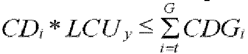 lorsque
 lorsque
 l'étape 2a consiste à calculer la capacité disponible qui est celle du système de stockage et qui correspond à la bande ayant la longueur de bande candidate LORIGy, sous la forme
 l'étape 2b consiste à calculer la capacité disponible qui est celle du système de stockage et qui correspond à la bande ayant la longueur de bande candidate LORIGy, sous la forme
 l'étape 2c consiste à attribuer la valeur t+1 à t et à effectuer l'étape a, dans laquelle t n'est pas supérieur à G.
 - Procédé selon l'une quelconque des revendications 1 et 2, dans lequel le calcul, par le dispositif de gestion, de la capacité disponible qui est celle du système de stockage et qui correspond à la bande ayant la longueur de bande candidate LORIGy comprend spécifiquement les étapes consistant à : effectuer, par le dispositif de gestion, l'étape a commençant à t=1 :déterminer si
 lorsque t=1, LORIGy est égal à LCUy ; ou lorsque t n'est pas égal à 1, LCUy est égal à
 lorsque
 lorsque
 lorsque
 l'étape 2a consiste à calculer la capacité disponible qui est celle du système de stockage et qui correspond à la bande ayant la longueur de bande candidate LORIGy, sous la forme
 l'étape 2b consiste à calculer la capacité disponible qui est celle du système de stockage et qui correspond à la bande ayant la longueur de bande candidate LORIGy, sous la forme
 l'étape 2c consiste à attribuer la valeur t+1 à t et à effectuer l'étape a, dans laquelle t n'est pas supérieur à G.
 - Procédé selon la revendication 3 ou 4, dans lequel le système de stockage comprend également un disque de secours, une capacité du disque de secours étant PC, et une capacité disponible du disque de secours étant

- Système de stockage, le système de stockage comprenant un dispositif de gestion et des disques disponibles,o dans lequel les disques disponibles sont groupés en G groupes de disques DGi disponibles, où i est un entier compris entre 1 et G, G est un entier, G n'étant pas inférieur à 2,o dans lequel une quantité de disques dans le groupe de disques DGi disponibles est Ni,o dans lequel une capacité de chaque disque Di du DGi est CDi, et une capacité CDx de chaque disque Dx d'un DGx est supérieure à une capacité CDx+1 de chaque disque Dx+1 d'un DGx+1, x étant un entier, et x étant un entier compris entre 1 et G-1,∘ dans lequel une longueur de bande qui peut être effectivement configurée dans le système de stockage est [r, z], où r et z sont des entiers positifs et z est supérieur à r, une bande étant formée d'une pluralité d'unités de bande distribuées en parallèle pour former une pluralité de disques des G groupes de disques disponibles lorsque des données doivent être stockées ; et
le dispositif de gestion comprenant un processeur et une interface, le processeur communiquant avec l'interface, et le processeur étant configuré pour effectuer l'un quelconque des procédés selon les revendications 1 à 5. - Produit-programme d'ordinateur comprenant des instructions qui, lorsque le programme est exécuté par un ordinateur, amènent l'ordinateur à mettre en œuvre le procédé selon les revendications 1 à 5.
Applications Claiming Priority (1)
| Application Number | Priority Date | Filing Date | Title |
|---|---|---|---|
| PCT/CN2017/109360 WO2019084917A1 (fr) | 2017-11-03 | 2017-11-03 | Procédé et appareil de calcul de capacité disponible de système de stockage |
Publications (3)
| Publication Number | Publication Date |
|---|---|
| EP3553664A1 EP3553664A1 (fr) | 2019-10-16 |
| EP3553664A4 EP3553664A4 (fr) | 2020-04-29 |
| EP3553664B1 true EP3553664B1 (fr) | 2022-07-27 |
Family
ID=64948910
Family Applications (1)
| Application Number | Title | Priority Date | Filing Date |
|---|---|---|---|
| EP17898328.4A Active EP3553664B1 (fr) | 2017-11-03 | 2017-11-03 | Procédé et appareil de calcul de capacité disponible de système de stockage |
Country Status (4)
| Country | Link |
|---|---|
| US (1) | US11385828B2 (fr) |
| EP (1) | EP3553664B1 (fr) |
| CN (1) | CN109196458B (fr) |
| WO (1) | WO2019084917A1 (fr) |
Families Citing this family (5)
| Publication number | Priority date | Publication date | Assignee | Title |
|---|---|---|---|---|
| CN114721585B (zh) * | 2021-01-06 | 2025-07-18 | 伊姆西Ip控股有限责任公司 | 存储管理方法、设备和计算机程序产品 |
| US11592988B2 (en) * | 2021-01-12 | 2023-02-28 | EMC IP Holding Company LLC | Utilizing a hybrid tier which mixes solid state device storage and hard disk drive storage |
| US11842074B2 (en) * | 2021-03-21 | 2023-12-12 | Vast Data Ltd. | Striping in a storage system |
| CN115237332A (zh) | 2021-04-23 | 2022-10-25 | 伊姆西Ip控股有限责任公司 | 管理盘方法、电子设备和计算机程序产品 |
| US12591383B1 (en) * | 2024-12-02 | 2026-03-31 | Dell Products L.P. | Allocating usable capacity from data storage drives having different capacities |
Family Cites Families (13)
| Publication number | Priority date | Publication date | Assignee | Title |
|---|---|---|---|---|
| JP3702231B2 (ja) * | 2002-01-31 | 2005-10-05 | 株式会社東芝 | ディスクアレイ装置及び同装置における動的記憶容量拡張方法 |
| US7302522B2 (en) * | 2004-12-27 | 2007-11-27 | Lsi Corporation | Optimizing I/O performance in a RAID subsystem using an adaptive maximum request size for a logical drive |
| US20060294300A1 (en) * | 2005-06-22 | 2006-12-28 | Seagate Technology Llc | Atomic cache transactions in a distributed storage system |
| CN101685380A (zh) * | 2008-09-27 | 2010-03-31 | 佛山市顺德区顺达电脑厂有限公司 | 磁盘阵列重组方法 |
| US8656131B2 (en) * | 2008-10-31 | 2014-02-18 | Dot Hill Systems Corporation | Method and apparatus for expanding a virtual storage device |
| JP2010282281A (ja) * | 2009-06-02 | 2010-12-16 | Hitachi Ltd | ディスクアレイ装置、及びその制御方法、並びにプログラム |
| CN101840360A (zh) * | 2009-10-28 | 2010-09-22 | 创新科存储技术有限公司 | Raid系统的快速重建方法及装置 |
| CN102043685A (zh) * | 2010-12-31 | 2011-05-04 | 成都市华为赛门铁克科技有限公司 | 独立磁盘冗余阵列系统及其数据恢复方法 |
| CN102819408B (zh) * | 2012-08-24 | 2016-01-06 | 记忆科技(深圳)有限公司 | 可动态调整条带深度的raid 0的实现方法及系统 |
| US9569268B2 (en) * | 2013-09-09 | 2017-02-14 | EMC IP Holding Company LLC | Resource provisioning based on logical profiles and objective functions |
| US20150199152A1 (en) * | 2014-01-16 | 2015-07-16 | Avalanche Technology, Inc. | Method of managing redundant array of independent disks (raid) groups in a solid state disk array |
| CN105760254B (zh) * | 2016-01-27 | 2019-08-06 | 四川效率源信息安全技术股份有限公司 | 一种基于raid1e的数据恢复方法 |
| CN106648469B (zh) * | 2016-12-29 | 2020-01-17 | 华为技术有限公司 | 一种缓存数据处理方法、装置和存储控制器 |
-
2017
- 2017-11-03 EP EP17898328.4A patent/EP3553664B1/fr active Active
- 2017-11-03 WO PCT/CN2017/109360 patent/WO2019084917A1/fr not_active Ceased
- 2017-11-03 CN CN201780011499.8A patent/CN109196458B/zh active Active
-
2019
- 2019-10-16 US US16/654,982 patent/US11385828B2/en active Active
Non-Patent Citations (1)
| Title |
|---|
| ONION: "Which Version of RAID is Best? RAID-0 vs. RAID-1 - Logical Increments Blog", 6 October 2016 (2016-10-06), pages 1 - 4, XP055836743, Retrieved from the Internet <URL:https://web.archive.org/web/20161009130605/http://blog.logicalincrements.com:80/2016/10/version-raid-best-raid-0-vs-raid-1/> [retrieved on 20210901] * |
Also Published As
| Publication number | Publication date |
|---|---|
| US11385828B2 (en) | 2022-07-12 |
| EP3553664A4 (fr) | 2020-04-29 |
| EP3553664A1 (fr) | 2019-10-16 |
| WO2019084917A1 (fr) | 2019-05-09 |
| US20200117386A1 (en) | 2020-04-16 |
| CN109196458B (zh) | 2020-12-01 |
| CN109196458A (zh) | 2019-01-11 |
Similar Documents
| Publication | Publication Date | Title |
|---|---|---|
| US10082965B1 (en) | Intelligent sparing of flash drives in data storage systems | |
| EP3553664B1 (fr) | Procédé et appareil de calcul de capacité disponible de système de stockage | |
| CN101971168B (zh) | 动态量化和提高分布式数据存储系统的可靠性 | |
| US8880801B1 (en) | Techniques for reliability and availability assessment of data storage configurations | |
| US10140041B1 (en) | Mapped RAID (redundant array of independent disks) in a data storage system with RAID extent sub-groups that are used to perform drive extent allocation and data striping for sequential data accesses to a storage object | |
| US10146447B1 (en) | Mapped RAID (redundant array of independent disks) in a data storage system with drive extents allocated to individual RAID extents from individual sub-groups of storage made up of ranges of logical block addresses defined across a group of hard disk drives | |
| US11797387B2 (en) | RAID stripe allocation based on memory device health | |
| US10126988B1 (en) | Assigning RAID extents and changing drive extent allocations within RAID extents when splitting a group of storage drives into partnership groups in a data storage system | |
| US10825477B2 (en) | RAID storage system with logical data group priority | |
| CN109725837B (zh) | 管理存储系统的方法、系统和计算机程序产品 | |
| US9274723B2 (en) | Storage apparatus and its control method | |
| US10552062B2 (en) | System and method for storing very large key value objects | |
| EP3336706A1 (fr) | Procédé et dispositif de stockage permettant de traiter des bandes dans un dispositif de stockage | |
| US8868864B2 (en) | Storage apparatus and storage apparatus control method | |
| CN110058804B (zh) | 数据存储系统和用于写入键值对的对象的方法 | |
| US10324794B2 (en) | Method for storage management and storage device | |
| CN116339644B (zh) | 一种独立磁盘冗余阵列创建方法、装置、设备及介质 | |
| US10296252B1 (en) | Reducing drive extent allocation changes while splitting a group of storage drives into partnership groups in response to addition of a storage drive to an array of storage drives in a data storage system that uses mapped RAID (redundant array of independent disks) technology | |
| CN109213428B (zh) | 用于管理存储系统的方法和设备 | |
| CN117193672A (zh) | 存储设备的数据处理方法及装置、存储介质及电子设备 | |
| CN112948279A (zh) | 管理存储系统中的访问请求的方法、设备和程序产品 | |
| CN115599314B (zh) | 数据冗余策略变更方法、装置、存储节点和存储介质 | |
| CN110096216B (zh) | 用于管理数据存储系统中的数据存储的方法、装置以及计算机程序产品 | |
| US20200042193A1 (en) | Method, storage system and computer program product for managing data storage | |
| CN111857560B (zh) | 用于管理数据的方法、设备和计算机程序产品 |
Legal Events
| Date | Code | Title | Description |
|---|---|---|---|
| STAA | Information on the status of an ep patent application or granted ep patent |
Free format text: STATUS: UNKNOWN |
|
| STAA | Information on the status of an ep patent application or granted ep patent |
Free format text: STATUS: THE INTERNATIONAL PUBLICATION HAS BEEN MADE |
|
| PUAI | Public reference made under article 153(3) epc to a published international application that has entered the european phase |
Free format text: ORIGINAL CODE: 0009012 |
|
| STAA | Information on the status of an ep patent application or granted ep patent |
Free format text: STATUS: REQUEST FOR EXAMINATION WAS MADE |
|
| 17P | Request for examination filed |
Effective date: 20180903 |
|
| AK | Designated contracting states |
Kind code of ref document: A1 Designated state(s): AL AT BE BG CH CY CZ DE DK EE ES FI FR GB GR HR HU IE IS IT LI LT LU LV MC MK MT NL NO PL PT RO RS SE SI SK SM TR |
|
| AX | Request for extension of the european patent |
Extension state: BA ME |
|
| R17P | Request for examination filed (corrected) |
Effective date: 20180903 |
|
| A4 | Supplementary search report drawn up and despatched |
Effective date: 20200327 |
|
| RIC1 | Information provided on ipc code assigned before grant |
Ipc: G06F 12/00 20060101AFI20200324BHEP Ipc: G06F 11/10 20060101ALI20200324BHEP Ipc: G06F 3/06 20060101ALI20200324BHEP |
|
| DAV | Request for validation of the european patent (deleted) | ||
| DAX | Request for extension of the european patent (deleted) | ||
| STAA | Information on the status of an ep patent application or granted ep patent |
Free format text: STATUS: EXAMINATION IS IN PROGRESS |
|
| 17Q | First examination report despatched |
Effective date: 20210323 |
|
| GRAP | Despatch of communication of intention to grant a patent |
Free format text: ORIGINAL CODE: EPIDOSNIGR1 |
|
| STAA | Information on the status of an ep patent application or granted ep patent |
Free format text: STATUS: GRANT OF PATENT IS INTENDED |
|
| INTG | Intention to grant announced |
Effective date: 20220307 |
|
| GRAS | Grant fee paid |
Free format text: ORIGINAL CODE: EPIDOSNIGR3 |
|
| GRAA | (expected) grant |
Free format text: ORIGINAL CODE: 0009210 |
|
| STAA | Information on the status of an ep patent application or granted ep patent |
Free format text: STATUS: THE PATENT HAS BEEN GRANTED |
|
| AK | Designated contracting states |
Kind code of ref document: B1 Designated state(s): AL AT BE BG CH CY CZ DE DK EE ES FI FR GB GR HR HU IE IS IT LI LT LU LV MC MK MT NL NO PL PT RO RS SE SI SK SM TR |
|
| REG | Reference to a national code |
Ref country code: CH Ref legal event code: EP |
|
| REG | Reference to a national code |
Ref country code: DE Ref legal event code: R096 Ref document number: 602017060043 Country of ref document: DE |
|
| REG | Reference to a national code |
Ref country code: AT Ref legal event code: REF Ref document number: 1507529 Country of ref document: AT Kind code of ref document: T Effective date: 20220815 |
|
| REG | Reference to a national code |
Ref country code: IE Ref legal event code: FG4D |
|
| REG | Reference to a national code |
Ref country code: LT Ref legal event code: MG9D |
|
| REG | Reference to a national code |
Ref country code: NL Ref legal event code: MP Effective date: 20220727 |
|
| PG25 | Lapsed in a contracting state [announced via postgrant information from national office to epo] |
Ref country code: SE Free format text: LAPSE BECAUSE OF FAILURE TO SUBMIT A TRANSLATION OF THE DESCRIPTION OR TO PAY THE FEE WITHIN THE PRESCRIBED TIME-LIMIT Effective date: 20220727 Ref country code: RS Free format text: LAPSE BECAUSE OF FAILURE TO SUBMIT A TRANSLATION OF THE DESCRIPTION OR TO PAY THE FEE WITHIN THE PRESCRIBED TIME-LIMIT Effective date: 20220727 Ref country code: PT Free format text: LAPSE BECAUSE OF FAILURE TO SUBMIT A TRANSLATION OF THE DESCRIPTION OR TO PAY THE FEE WITHIN THE PRESCRIBED TIME-LIMIT Effective date: 20221128 Ref country code: NO Free format text: LAPSE BECAUSE OF FAILURE TO SUBMIT A TRANSLATION OF THE DESCRIPTION OR TO PAY THE FEE WITHIN THE PRESCRIBED TIME-LIMIT Effective date: 20221027 Ref country code: NL Free format text: LAPSE BECAUSE OF FAILURE TO SUBMIT A TRANSLATION OF THE DESCRIPTION OR TO PAY THE FEE WITHIN THE PRESCRIBED TIME-LIMIT Effective date: 20220727 Ref country code: LV Free format text: LAPSE BECAUSE OF FAILURE TO SUBMIT A TRANSLATION OF THE DESCRIPTION OR TO PAY THE FEE WITHIN THE PRESCRIBED TIME-LIMIT Effective date: 20220727 Ref country code: LT Free format text: LAPSE BECAUSE OF FAILURE TO SUBMIT A TRANSLATION OF THE DESCRIPTION OR TO PAY THE FEE WITHIN THE PRESCRIBED TIME-LIMIT Effective date: 20220727 Ref country code: FI Free format text: LAPSE BECAUSE OF FAILURE TO SUBMIT A TRANSLATION OF THE DESCRIPTION OR TO PAY THE FEE WITHIN THE PRESCRIBED TIME-LIMIT Effective date: 20220727 Ref country code: ES Free format text: LAPSE BECAUSE OF FAILURE TO SUBMIT A TRANSLATION OF THE DESCRIPTION OR TO PAY THE FEE WITHIN THE PRESCRIBED TIME-LIMIT Effective date: 20220727 |
|
| REG | Reference to a national code |
Ref country code: AT Ref legal event code: MK05 Ref document number: 1507529 Country of ref document: AT Kind code of ref document: T Effective date: 20220727 |
|
| PG25 | Lapsed in a contracting state [announced via postgrant information from national office to epo] |
Ref country code: PL Free format text: LAPSE BECAUSE OF FAILURE TO SUBMIT A TRANSLATION OF THE DESCRIPTION OR TO PAY THE FEE WITHIN THE PRESCRIBED TIME-LIMIT Effective date: 20220727 Ref country code: IS Free format text: LAPSE BECAUSE OF FAILURE TO SUBMIT A TRANSLATION OF THE DESCRIPTION OR TO PAY THE FEE WITHIN THE PRESCRIBED TIME-LIMIT Effective date: 20221127 Ref country code: HR Free format text: LAPSE BECAUSE OF FAILURE TO SUBMIT A TRANSLATION OF THE DESCRIPTION OR TO PAY THE FEE WITHIN THE PRESCRIBED TIME-LIMIT Effective date: 20220727 Ref country code: GR Free format text: LAPSE BECAUSE OF FAILURE TO SUBMIT A TRANSLATION OF THE DESCRIPTION OR TO PAY THE FEE WITHIN THE PRESCRIBED TIME-LIMIT Effective date: 20221028 |
|
| PG25 | Lapsed in a contracting state [announced via postgrant information from national office to epo] |
Ref country code: SM Free format text: LAPSE BECAUSE OF FAILURE TO SUBMIT A TRANSLATION OF THE DESCRIPTION OR TO PAY THE FEE WITHIN THE PRESCRIBED TIME-LIMIT Effective date: 20220727 Ref country code: RO Free format text: LAPSE BECAUSE OF FAILURE TO SUBMIT A TRANSLATION OF THE DESCRIPTION OR TO PAY THE FEE WITHIN THE PRESCRIBED TIME-LIMIT Effective date: 20220727 Ref country code: DK Free format text: LAPSE BECAUSE OF FAILURE TO SUBMIT A TRANSLATION OF THE DESCRIPTION OR TO PAY THE FEE WITHIN THE PRESCRIBED TIME-LIMIT Effective date: 20220727 Ref country code: CZ Free format text: LAPSE BECAUSE OF FAILURE TO SUBMIT A TRANSLATION OF THE DESCRIPTION OR TO PAY THE FEE WITHIN THE PRESCRIBED TIME-LIMIT Effective date: 20220727 Ref country code: AT Free format text: LAPSE BECAUSE OF FAILURE TO SUBMIT A TRANSLATION OF THE DESCRIPTION OR TO PAY THE FEE WITHIN THE PRESCRIBED TIME-LIMIT Effective date: 20220727 |
|
| REG | Reference to a national code |
Ref country code: DE Ref legal event code: R097 Ref document number: 602017060043 Country of ref document: DE |
|
| PG25 | Lapsed in a contracting state [announced via postgrant information from national office to epo] |
Ref country code: SK Free format text: LAPSE BECAUSE OF FAILURE TO SUBMIT A TRANSLATION OF THE DESCRIPTION OR TO PAY THE FEE WITHIN THE PRESCRIBED TIME-LIMIT Effective date: 20220727 Ref country code: EE Free format text: LAPSE BECAUSE OF FAILURE TO SUBMIT A TRANSLATION OF THE DESCRIPTION OR TO PAY THE FEE WITHIN THE PRESCRIBED TIME-LIMIT Effective date: 20220727 |
|
| PLBE | No opposition filed within time limit |
Free format text: ORIGINAL CODE: 0009261 |
|
| STAA | Information on the status of an ep patent application or granted ep patent |
Free format text: STATUS: NO OPPOSITION FILED WITHIN TIME LIMIT |
|
| PG25 | Lapsed in a contracting state [announced via postgrant information from national office to epo] |
Ref country code: MC Free format text: LAPSE BECAUSE OF FAILURE TO SUBMIT A TRANSLATION OF THE DESCRIPTION OR TO PAY THE FEE WITHIN THE PRESCRIBED TIME-LIMIT Effective date: 20220727 Ref country code: AL Free format text: LAPSE BECAUSE OF FAILURE TO SUBMIT A TRANSLATION OF THE DESCRIPTION OR TO PAY THE FEE WITHIN THE PRESCRIBED TIME-LIMIT Effective date: 20220727 |
|
| REG | Reference to a national code |
Ref country code: CH Ref legal event code: PL |
|
| 26N | No opposition filed |
Effective date: 20230502 |
|
| GBPC | Gb: european patent ceased through non-payment of renewal fee |
Effective date: 20221103 |
|
| REG | Reference to a national code |
Ref country code: BE Ref legal event code: MM Effective date: 20221130 |
|
| PG25 | Lapsed in a contracting state [announced via postgrant information from national office to epo] |
Ref country code: LI Free format text: LAPSE BECAUSE OF NON-PAYMENT OF DUE FEES Effective date: 20221130 Ref country code: CH Free format text: LAPSE BECAUSE OF NON-PAYMENT OF DUE FEES Effective date: 20221130 |
|
| PG25 | Lapsed in a contracting state [announced via postgrant information from national office to epo] |
Ref country code: SI Free format text: LAPSE BECAUSE OF FAILURE TO SUBMIT A TRANSLATION OF THE DESCRIPTION OR TO PAY THE FEE WITHIN THE PRESCRIBED TIME-LIMIT Effective date: 20220727 Ref country code: LU Free format text: LAPSE BECAUSE OF NON-PAYMENT OF DUE FEES Effective date: 20221103 |
|
| PG25 | Lapsed in a contracting state [announced via postgrant information from national office to epo] |
Ref country code: IE Free format text: LAPSE BECAUSE OF NON-PAYMENT OF DUE FEES Effective date: 20221103 Ref country code: GB Free format text: LAPSE BECAUSE OF NON-PAYMENT OF DUE FEES Effective date: 20221103 |
|
| PG25 | Lapsed in a contracting state [announced via postgrant information from national office to epo] |
Ref country code: FR Free format text: LAPSE BECAUSE OF NON-PAYMENT OF DUE FEES Effective date: 20221130 Ref country code: BE Free format text: LAPSE BECAUSE OF NON-PAYMENT OF DUE FEES Effective date: 20221130 |
|
| PG25 | Lapsed in a contracting state [announced via postgrant information from national office to epo] |
Ref country code: HU Free format text: LAPSE BECAUSE OF FAILURE TO SUBMIT A TRANSLATION OF THE DESCRIPTION OR TO PAY THE FEE WITHIN THE PRESCRIBED TIME-LIMIT; INVALID AB INITIO Effective date: 20171103 |
|
| PG25 | Lapsed in a contracting state [announced via postgrant information from national office to epo] |
Ref country code: CY Free format text: LAPSE BECAUSE OF FAILURE TO SUBMIT A TRANSLATION OF THE DESCRIPTION OR TO PAY THE FEE WITHIN THE PRESCRIBED TIME-LIMIT Effective date: 20220727 |
|
| PG25 | Lapsed in a contracting state [announced via postgrant information from national office to epo] |
Ref country code: MK Free format text: LAPSE BECAUSE OF FAILURE TO SUBMIT A TRANSLATION OF THE DESCRIPTION OR TO PAY THE FEE WITHIN THE PRESCRIBED TIME-LIMIT Effective date: 20220727 Ref country code: IT Free format text: LAPSE BECAUSE OF FAILURE TO SUBMIT A TRANSLATION OF THE DESCRIPTION OR TO PAY THE FEE WITHIN THE PRESCRIBED TIME-LIMIT Effective date: 20220727 |
|
| PG25 | Lapsed in a contracting state [announced via postgrant information from national office to epo] |
Ref country code: BG Free format text: LAPSE BECAUSE OF FAILURE TO SUBMIT A TRANSLATION OF THE DESCRIPTION OR TO PAY THE FEE WITHIN THE PRESCRIBED TIME-LIMIT Effective date: 20220727 |
|
| PG25 | Lapsed in a contracting state [announced via postgrant information from national office to epo] |
Ref country code: MT Free format text: LAPSE BECAUSE OF FAILURE TO SUBMIT A TRANSLATION OF THE DESCRIPTION OR TO PAY THE FEE WITHIN THE PRESCRIBED TIME-LIMIT Effective date: 20220727 |
|
| PG25 | Lapsed in a contracting state [announced via postgrant information from national office to epo] |
Ref country code: TR Free format text: LAPSE BECAUSE OF FAILURE TO SUBMIT A TRANSLATION OF THE DESCRIPTION OR TO PAY THE FEE WITHIN THE PRESCRIBED TIME-LIMIT Effective date: 20220727 |
|
| PGFP | Annual fee paid to national office [announced via postgrant information from national office to epo] |
Ref country code: DE Payment date: 20250930 Year of fee payment: 9 |