EP3553839B1 - Limiteur de courant de défaut supraconducteur - Google Patents
Limiteur de courant de défaut supraconducteur Download PDFInfo
- Publication number
- EP3553839B1 EP3553839B1 EP19161848.7A EP19161848A EP3553839B1 EP 3553839 B1 EP3553839 B1 EP 3553839B1 EP 19161848 A EP19161848 A EP 19161848A EP 3553839 B1 EP3553839 B1 EP 3553839B1
- Authority
- EP
- European Patent Office
- Prior art keywords
- superconducting wire
- superconducting
- inner container
- heat dissipation
- dissipation elements
- Prior art date
- Legal status (The legal status is an assumption and is not a legal conclusion. Google has not performed a legal analysis and makes no representation as to the accuracy of the status listed.)
- Not-in-force
Links
Images

Classifications
-
- H—ELECTRICITY
- H10—SEMICONDUCTOR DEVICES; ELECTRIC SOLID-STATE DEVICES NOT OTHERWISE PROVIDED FOR
- H10N—ELECTRIC SOLID-STATE DEVICES NOT OTHERWISE PROVIDED FOR
- H10N60/00—Superconducting devices
- H10N60/30—Devices switchable between superconducting and normal states
-
- H—ELECTRICITY
- H02—GENERATION; CONVERSION OR DISTRIBUTION OF ELECTRIC POWER
- H02H—EMERGENCY PROTECTIVE CIRCUIT ARRANGEMENTS
- H02H9/00—Emergency protective circuit arrangements for limiting excess current or voltage without disconnection
- H02H9/02—Emergency protective circuit arrangements for limiting excess current or voltage without disconnection responsive to excess current
- H02H9/023—Current limitation using superconducting elements
-
- H—ELECTRICITY
- H01—ELECTRIC ELEMENTS
- H01F—MAGNETS; INDUCTANCES; TRANSFORMERS; SELECTION OF MATERIALS FOR THEIR MAGNETIC PROPERTIES
- H01F6/00—Superconducting magnets; Superconducting coils
- H01F6/02—Quenching; Protection arrangements during quenching
-
- H—ELECTRICITY
- H01—ELECTRIC ELEMENTS
- H01F—MAGNETS; INDUCTANCES; TRANSFORMERS; SELECTION OF MATERIALS FOR THEIR MAGNETIC PROPERTIES
- H01F6/00—Superconducting magnets; Superconducting coils
- H01F2006/001—Constructive details of inductive current limiters
-
- Y—GENERAL TAGGING OF NEW TECHNOLOGICAL DEVELOPMENTS; GENERAL TAGGING OF CROSS-SECTIONAL TECHNOLOGIES SPANNING OVER SEVERAL SECTIONS OF THE IPC; TECHNICAL SUBJECTS COVERED BY FORMER USPC CROSS-REFERENCE ART COLLECTIONS [XRACs] AND DIGESTS
- Y02—TECHNOLOGIES OR APPLICATIONS FOR MITIGATION OR ADAPTATION AGAINST CLIMATE CHANGE
- Y02E—REDUCTION OF GREENHOUSE GAS [GHG] EMISSIONS, RELATED TO ENERGY GENERATION, TRANSMISSION OR DISTRIBUTION
- Y02E40/00—Technologies for an efficient electrical power generation, transmission or distribution
- Y02E40/60—Superconducting electric elements or equipment; Power systems integrating superconducting elements or equipment
Definitions
- This disclosure relates to superconducting fault current limiters.
- Fault current limiters can be used to limit potentially damaging fault currents in electric power distribution systems, particularly large-scale high-power networks such as grid-scale transformers or substations. Fault currents are abnormal currents in the electric power distribution system resulting from a fault such as a short circuit.
- Superconducting fault current limiters SFCLs exploit fundamental properties of superconductivity, principally the extremely rapid loss of superconductivity (known as "quenching") above a critical combination of temperature, current density and magnetic field strength, to limit fault currents.
- an SFCL In normal operation, when a current density in an SFCL is below a critical current density, a superconductor in the SFCL has a low impedance and is in a superconducting state. To maintain the superconductor in a superconducting, low impedance state during normal operation, the superconductor is operated below a critical combination of temperature, current density and magnetic field strength.
- an SFCL comprises a superconductor positioned within a cryostat, or similar cooling tank, in order to maintain the superconductor below a critical temperature.
- the current density in the SFCL exceeds the critical current density, the superconductor's impedance becomes high and the superconductor rapidly stops being superconducting.
- the high impedance of the superconductor limits the fault current, thereby reducing its potentially damaging effects.
- Example SFCLs are disclosed in United States Patent No 8,037,695 B2 and International Patent Application Publication WO 2015/022423 A1 , the latter of which aims to provide a low inductance during normal operation and a rapid and even quench under fault current conditions.
- SFCLs based on superconducting wires having spaced heat dissipation elements, such as metallic fins or plates, projecting from the wires are known from Y. Shirai et al, IEEE TRANSACTIONS ON APPLIED SUPERCONDUCTIVITY, vol. 26, no. 3, 5602404, 2016 , WO 2017/010326 A1 and corresponding US 2018/152016 A1 , or EP 2 711 998 A1 , for example.
- the heat dissipation elements improve the thermal diffusivity between the superconducting wire and the cooling medium during and after a fault.
- the additional thermal surface area provided by the heat dissipation elements results in a faster rate of heat dissipation through the cooling medium, thereby reducing the cool down time necessary for resumption of normal operation. Reducing the cool down time of the superconducting wire in turn reduces an outage time in the event of a fault.
- the electrically insulating coating helps to prevent short circuits between the heat dissipation elements.
- a shorter superconducting wire may be used, whilst still providing a same thermal surface area, because the need for other types of thermal stabilisers generally used in SFCLs can be reduced or eliminated. Therefore the size and weight of the SFCL may also be reduced.
- the heat dissipation elements may project from the superconducting wire perpendicularly to the length direction of the superconducting wire. This helps to prevent short circuits between the heat dissipation elements.
- the heat dissipation elements may be spaced apart from one another along the superconducting wire by a distance that ensures a sufficient voltage withstand when the superconducting wire becomes non-superconducting.
- the heat dissipation elements may be spaced apart from one another by a distance such that they are electrically insulated from one another even if/when there is a large voltage drop along the length of the superconducting wire when the superconducting wire is quenched. Therefore, short circuits may be prevented.
- the superconducting wire may be arranged such that when the superconducting wire carries a current, any generated magnetic fields are substantially cancelled by each other. By balancing the generated magnetic field, an even quench may be achieved.
- a first portion of the superconducting wire may be spiralled around a first axis, and a second portion of the superconducting wire may be spiralled around a second axis. Further, the first and second portions may be arranged such that, when the superconducting wire carries a current, a magnetic field generated from the current flowing in the first portion may be substantially cancelled by a magnetic field generated from the current flowing in the second portion. This configuration can enable an even quench to be achieved.
- the first and second portions of superconducting wire may be spiralled around respective cores centred on the respective axes.
- the first and second portions may form coils around respective cores.
- the heat dissipation elements projecting from the first portion of superconducting wire may project away from the first axis, and the heat dissipation elements projecting from the second portion of superconducting wire may project away from the second axis. This also helps to prevent short circuits between the heat dissipation elements.
- the cryostatic cooling system may comprise an outer container and an electrically insulating inner container positioned within the outer container, the inner container containing the cooling medium.
- the electrically insulating inner container helps to mitigate electrical discharges during normal operation when the superconducting wire is superconducting. As the inner electrically insulating container provides electrical and thermal insulation, arcing between the heat dissipation elements and the outer container can be reduced, or prevented.
- a side wall thickness of the inner container may taper from a maximum at a first end of the inner container, to a minimum at an opposite second end of the inner container, and electrical leads for joining to respective ends of the superconducting wire may pass into the inner container at or adjacent the first end.
- the heat dissipation elements in closest proximity to the second end of the inner container may project a greater distance from the superconducting wire and/or may have a greater surface area than the heat dissipation elements in closest proximity to the first end of the inner container. Additionally or alternatively, there may be a greater density of heat dissipation elements at the second end than at the first end. This results in an increased rate of cooling of the superconducting wire whilst ensuring that the superconducting wire is electrically insulated from the outer container.
- thermal flows may be unbalanced across the superconducting fault current limiter.
- a gap may space the inner container from the outer container, the gap containing a vacuum.
- the inner container may be flush, i.e. in physical contact, with the inside walls of the outer container.
- a plurality of cooling elements may project from the outer container through the inner container and into the cooling medium.
- the cooling elements may be formed from a highly thermally conductive material, such as copper, in order to further enhance the cooling of the superconducting wire.
- Each cooling element may be spaced from the heat dissipation elements by at least a distance capable of preventing and/or limiting the possibility of electrical discharges between the heat dissipation elements and the cooling elements (and thence the outer container).
- Superconducting fault current limiters can be implemented in electric power distribution systems to limit potentially damaging fault currents resulting from faults, such as short circuits.
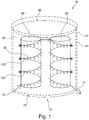
- a superconducting fault current limiter (SFCL) 10 comprises a cryostatic cooling system 20.
- the cryostatic cooling system 20 comprises an outer container 22, and an inner container 24, wherein the inner container 24 is positioned within the outer container 22.
- the inner container 24 contains a cooling medium 26 capable of reaching superconducting low temperatures suitable for maintaining superconductors in a superconducting state.
- the cooling medium 26 may be liquid nitrogen and/or liquid helium, for example.
- the outer container 22 is formed from a thermally conductive material, such as copper.
- the outer container 22 may be additionally cooled from the outside.
- the outer container 22 has a low electrical conductivity at low superconducting temperatures.
- the cryostatic cooling system 20 may be maintained within a vacuum in order to shield the cryostatic cooling system 20 from room temperature.
- the inner container 24 is formed from any suitable electrically insulating material, such as alumina and/or resin, such as epoxy resin, and provides electrical insulation and thermal insulation.
- the inner container 24 may be spaced from the inside of the outer container 22 by a vacuum. In other words, a gap containing a vacuum may space the inner container 24 from the inside of the outer container 22.
- the outer container 22 may be flush with the inner container 24 such that there is no spacing between the outer container 22 and the inner container 24.
- resin tape may be layered on the inner surface of the outer container 22 to form the inner container 24.
- a superconducting wire 30 is positioned in the cooling medium 26 within the inner container 24.
- the superconducting wire 30 may be formed from any suitable superconducting material, and may be provided in any suitable form, for example a tape, a wire, a multi-strand wire, or a multi-core arrangement.
- the superconducting wire 30 may be spiralled (i.e. coiled) around one or more axes.
- the superconducting wire 30 is coiled around a first core 50 and a second core 60.
- the first and second cores 50, 60 support the superconducting wire 30 within the cryostatic cooling system 20.
- the first and second cores 50, 60 may be formed from an electrically-insulating material in order to prevent short-circuits between the turns of the coil of superconducting wire 30.
- the turns of the coil of superconducting wire 30 are spaced from one another along a length of the first and second cores 50, 60 to prevent short circuits between the turns, even if/when high fault currents are passed through the superconducting wire 30.
- the inner container 24 has a first end 70 and an opposite second end 80. Electrical current enters and exits the cryostatic cooling system 20 via the respective leads 72, 74 which pass into the inner container 24 at or adjacent the first end 70.
- a current flows through the leads 72, 74 and the superconducting wire 30, as indicated in Figure 1 by arrows.
- the leads 72, 74 are shown entering the inner container 24 at its base, and the first and second cores 50, 60 are attached to the base.
- the leads 72, 74 may enter at the top of the inner container 24, and the first and second cores 50, 60 may be attached to the top.
- the top is a lid (removable to allow the cooling medium to be poured in to the inner container 24)
- this arrangement can facilitate installation and maintenance of the SFCL.
- the superconducting wire 30 may be arranged within the inner container 24 so that any magnetic field generated from a current flowing though the superconducting wire 30 is substantially cancelled.
- the magnetic field generated by a current flowing in a first portion of superconducting wire 30 spiralled around the first core 50 is substantially cancelled by the magnetic field generated by the current flowing in a second portion of superconducting wire 30 spiralled around the second core 60.
- the overall direction of current in the first portion of superconducting wire 30 is equal and opposite to the overall direction of current in the second portion of superconducting wire 30. Therefore, the respective generated magnetic field vectors resulting from the current in the first and second portions of superconducting wire 30 cancel with each other. This promotes a substantially uniform magnetic field density across the SFCL 10, which leads to even quenching.
- the superconducting wire 30 heats up rapidly. Once the fault has been removed from the system, the superconducting wire 30 must be cooled to below its critical temperature in order to return to a superconducting state for normal operation. As shown in Figure 1 , heat dissipation elements 100 spaced along and projecting from the superconducting wire 30 improve the thermal diffusivity between the superconducting wire 30 and the cooling medium 26 during and after the fault so that heat may be dissipated effectively. Therefore, the superconducting wire 30 can be cooled quickly, and returned to its superconducting state quickly.
- the heat dissipation elements 100 may be any shape suitable for improving the thermal diffusivity and reducing thermal resistance to the cooling medium 26 (for example, wires and/or fins).
- the heat dissipation elements 100 are typically formed from a highly thermally conductive material, such as copper.
- the heat dissipation elements 100 project from the superconducting wire 30 perpendicularly to the length direction of the superconducting wire 30, and also perpendicularly to the long axes of the cores 50, 60. This reduces the possibility of short circuits between the heat dissipation elements 100 themselves, and between the heat dissipation elements 100 and the superconducting wire 30.
- the heat dissipation elements 100 are also spaced apart from one another along the length of the superconducting wire 30 by a distance that ensures a sufficient voltage withstand.
- the heat dissipation elements 100 must be spaced from one another along the superconducting wire 30 by a distance sufficient to prevent electrical discharges between the heat dissipation elements 100.
- the heat dissipation elements 100 are further electrically insulated from one another by providing a thin coating of electrically insulating material to each of the heat dissipation elements 100.
- the inner container 24 reduces the possibility of electrical discharges between the heat dissipation elements 100 and the outer container 22. As the inner container is formed from an electrically insulating material, electrical discharge or "arcing" between the heat dissipation elements 100 and the outer container 22 can be prevented.
- the side wall thickness of the inner container 24 may vary along the length of the inner container.
- the side wall thickness of the inner container 24 may taper from a maximum thickness at the first end 70 of the inner container 24, to a minimum thickness at the second end 80 of inner container.
- the leads 72, 74 are at the first end 70 of the inner container 24, the highest voltage value across the cryostatic cooling system 20 is at the first end 70.
- the lowest voltage value across the cryostatic cooling system is at the second end 80.
- the tapering of the side wall thickness of the inner container 24 allows the overall electric field to be balanced.
- the side wall may have twice the thickness at the second end than at the first end.
- a cold source (not shown in Figure 1 ) of the cryostatic cooling system 20 may be positioned at the first end 70 close to where the leads 72, 74 enter the inner container 24. The leads 72, 74 may then be cooled by the cold source.
- the lengths and/or surface areas of the heat dissipation elements 100 may be varied along the length of the superconducting wire 30 such that heat dissipation elements closest to the second end 80 of the inner container 24 have a greater cooling effectiveness than heat dissipation elements closest to the first end 70. Additionally or alternatively, there may be a greater density of heat dissipation elements at the second end than at the first end.
- the relationship between the lengths of the heat dissipation elements 100 and the variation of the side wall thickness of the inner container 24 may be such that there is a constant spacing between each of the heat dissipation elements 100 and the inside of the inner container 24, thereby maintaining electrical insulation from the outer container 22.
- Figure 2 shows a close up view of part of an SFCL 10 according to another example.
- the inner container 24 has a thickness d2, and forms an insulating coating to the outer container 22.
- the superconducting wire 30 is coiled around two cores ( Figure 2 shows the superconducting wire 30 coiled around the second core 60), and a plurality of heat dissipation elements 100 project from the superconducting wire 30 into the cooling medium 26.
- a plurality of cooling elements 110 project from the outer container 22, through the inner container 24, and into the cooling medium 26.
- the cooling elements 110 may be any shape (for example, wires and/or fins) suitable for improving the thermal diffusivity and reducing thermal resistance from the cooling medium 26 to the outer container 24. Accordingly, the cooling elements 110 can be formed from a highly thermally conductive material, such as copper. The cooling elements 110 further enhance the cooling of the superconducting wire 30.
- each cooling element 110 is appropriately spaced from the heat dissipation elements 100.
- the electrical conductance of a material between two objects is proportional to the material's electrical conductivity and the distance between the two objects. If the conductivity of the cooling medium 26 is ⁇ 1, and the conductivity of the inner container 24 is ⁇ 2, at a position of closest approach of a cooling element 100 to the inner container 24, the conductance between the heat dissipation elements 100 and the outer container 22 is ⁇ 1 ⁇ d1+ ⁇ 2 ⁇ d2, where d1 is the smallest distance between the heat dissipation elements 100 and the inner container 24, and d2 is the thickness of the inner container 24.
- the cooling elements 110 should then be located such that they are spaced from the heat dissipation elements 100 by a distance providing a conductance of at least ⁇ 1 ⁇ d1+ ⁇ 2 ⁇ d2 between each cooling element 110 and the closest heat dissipation element 100.
- ⁇ 1 ⁇ d1+ ⁇ 2 ⁇ d2 ⁇ 1 ⁇ d3, where d3 is the distance of closest approach of the heat dissipation elements 100 to the cooling elements 110.
- each cooling element is spaced at least a distance d3 away from the heat dissipation elements 100, enhanced cooling of the superconducting wire 30 can be achieved without increasing the possibility of electrical discharge between the heat dissipation elements 100 and the outer container 22.
- SFCLs as described herein may be advantageously used in aeronautical or marine applications.
Landscapes
- Engineering & Computer Science (AREA)
- Power Engineering (AREA)
- Containers, Films, And Cooling For Superconductive Devices (AREA)
- Emergency Protection Circuit Devices (AREA)
Claims (9)
- Limiteur supraconducteur de courant de défaut (10) comprenant :un système de refroidissement cryostatique (20) pour contenir un milieu de refroidissement (26) ;un fil supraconducteur (30) immergé dans le milieu de refroidissement (26) et configuré pour transporter un courant, le fil supraconducteur (30) devenant non supraconducteur au-dessus d'une densité de courant critique ; etune pluralité d'éléments de dissipation thermique (100) espacés le long et faisant saillie du fil supraconducteur (30), moyennant quoi les éléments de dissipation thermique (100) transfèrent la chaleur du fil supraconducteur (30) dans le milieu de refroidissement (26), caractérisé en ce que les éléments de dissipation thermique (100) ont un revêtement électriquement isolant.
- Limiteur supraconducteur de courant de défaut (10) selon la revendication 1, dans lequel les éléments de dissipation thermique (100) font saillie du fil supraconducteur (30) perpendiculairement à la direction de longueur du fil supraconducteur (30).
- Limiteur supraconducteur de courant de défaut (10) selon l'une quelconque des revendications précédentes, dans lequel :une première partie du fil supraconducteur (30) est enroulée en spirale autour d'un premier axe ;une seconde partie du fil supraconducteur (30) est enroulée en spirale autour d'un deuxième axe ; etles première et seconde parties sont agencées de telle sorte que, lorsque le fil supraconducteur (30) transporte un courant, un champ magnétique généré par le courant circulant dans la première partie soit sensiblement annulé par un champ magnétique généré par le courant circulant dans la seconde partie.
- Limiteur supraconducteur de courant de défaut (10) selon la revendication 3, dans lequel les éléments de dissipation thermique faisant saillie depuis la première partie du fil supraconducteur font saillie en éloignement du premier axe, et les éléments de dissipation thermique font saillie depuis la seconde partie du fil supraconducteur faisant saillie en éloignement du deuxième axe.
- Limiteur supraconducteur de courant de défaut (10) selon l'une quelconque des revendications précédentes, dans lequel le système de refroidissement cryostatique (20) comprend :un récipient extérieur (22) ; etun récipient intérieur électriquement isolant (24) positionné à l'intérieur du récipient extérieur (22), le récipient intérieur (24) contenant le milieu de refroidissement (26).
- Limiteur supraconducteur de courant de défaut (10) selon la revendication 5, dans lequel une épaisseur de paroi latérale du récipient intérieur (24) diminue depuis un maximum au niveau d'une première extrémité (70) du récipient intérieur (24), jusqu'à un minimum au niveau d'une seconde extrémité opposée (80) du récipient intérieur (24) et des fils électriques (72, 74) destinés à se joindre aux extrémités respectives du fil supraconducteur (30) passent dans le récipient intérieur (24) au niveau ou adjacent à la première extrémité (70).
- Limiteur supraconducteur de courant de défaut (10) selon la revendication 6, dans lequel les éléments de dissipation thermique (100) les plus proches de la seconde extrémité (80) du récipient intérieur (24) font saillie sur une plus grande distance du fil supraconducteur (30), et / ou ont une plus grande surface que les éléments de dissipation thermique (100) les plus proches de la première extrémité (70) du récipient intérieur (24).
- Limiteur supraconducteur de courant de défaut (10) selon l'une quelconque des revendications 5 à 7, dans lequel un espace sépare le récipient intérieur (24) du récipient extérieur (22), l'espace contenant un vide.
- Limiteur supraconducteur de courant de défaut (10) selon l'une quelconque des revendications 5 à 8, dans lequel une pluralité d'éléments de refroidissement (110) font saillie du récipient extérieur (22) à travers le récipient intérieur (24) et dans le milieu de refroidissement (26).
Applications Claiming Priority (1)
| Application Number | Priority Date | Filing Date | Title |
|---|---|---|---|
| GBGB1805866.9A GB201805866D0 (en) | 2018-04-09 | 2018-04-09 | Superconducting fault current limiter |
Publications (2)
| Publication Number | Publication Date |
|---|---|
| EP3553839A1 EP3553839A1 (fr) | 2019-10-16 |
| EP3553839B1 true EP3553839B1 (fr) | 2020-07-29 |
Family
ID=62202755
Family Applications (1)
| Application Number | Title | Priority Date | Filing Date |
|---|---|---|---|
| EP19161848.7A Not-in-force EP3553839B1 (fr) | 2018-04-09 | 2019-03-11 | Limiteur de courant de défaut supraconducteur |
Country Status (4)
| Country | Link |
|---|---|
| US (1) | US11527885B2 (fr) |
| EP (1) | EP3553839B1 (fr) |
| CN (1) | CN110365000B (fr) |
| GB (1) | GB201805866D0 (fr) |
Families Citing this family (2)
| Publication number | Priority date | Publication date | Assignee | Title |
|---|---|---|---|---|
| RU195807U1 (ru) * | 2019-12-02 | 2020-02-05 | Закрытое акционерное общество "СуперОкс" (ЗАО "СуперОкс") | Высоковольтное токоограничивающее устройство |
| CN114966497A (zh) * | 2022-05-19 | 2022-08-30 | 东部超导科技(苏州)有限公司 | 一种临界电流测试装置和方法 |
Family Cites Families (6)
| Publication number | Priority date | Publication date | Assignee | Title |
|---|---|---|---|---|
| US6657533B2 (en) * | 1998-11-25 | 2003-12-02 | American Semiconductor Corporation | Superconducting conductors and their method of manufacture |
| US8037695B2 (en) | 2003-07-04 | 2011-10-18 | Rolls-Royce Plc | Fault current limiter |
| KR100662754B1 (ko) * | 2005-12-02 | 2007-01-02 | 엘에스산전 주식회사 | 초전도 저항형 한류기 |
| WO2012157494A1 (fr) * | 2011-05-18 | 2012-11-22 | 住友電気工業株式会社 | Limiteur de courant de défaut |
| EP3001431A1 (fr) | 2013-08-16 | 2016-03-30 | Energy Technologies Institute LLP | Dispositif pour limiteur de courant et limiteur de courant comprenant ce dispositif |
| JPWO2017010326A1 (ja) * | 2015-07-16 | 2018-04-26 | 住友電気工業株式会社 | 超電導線材および限流器 |
-
2018
- 2018-04-09 GB GBGB1805866.9A patent/GB201805866D0/en not_active Ceased
-
2019
- 2019-03-11 EP EP19161848.7A patent/EP3553839B1/fr not_active Not-in-force
- 2019-03-12 US US16/299,765 patent/US11527885B2/en active Active
- 2019-04-09 CN CN201910280243.8A patent/CN110365000B/zh not_active Expired - Fee Related
Non-Patent Citations (1)
| Title |
|---|
| None * |
Also Published As
| Publication number | Publication date |
|---|---|
| US11527885B2 (en) | 2022-12-13 |
| CN110365000B (zh) | 2023-05-26 |
| EP3553839A1 (fr) | 2019-10-16 |
| GB201805866D0 (en) | 2018-05-23 |
| US20190312428A1 (en) | 2019-10-10 |
| CN110365000A (zh) | 2019-10-22 |
Similar Documents
| Publication | Publication Date | Title |
|---|---|---|
| KR100662754B1 (ko) | 초전도 저항형 한류기 | |
| US5379020A (en) | High-temperature superconductor and its use | |
| US8989828B2 (en) | Superconducting magnet apparatus | |
| EP4115432A1 (fr) | Câble supraconducteur cloisonné | |
| US20230146164A1 (en) | Passive quench protection techniques for non-insulated superconducting magnets | |
| US8233952B2 (en) | Superconducting magnet | |
| EP3553839B1 (fr) | Limiteur de courant de défaut supraconducteur | |
| Ottonello et al. | The largest italian SMES | |
| US4486800A (en) | Thermal method for making a fast transition of a superconducting winding from the superconducting into the normal-conducting state, and apparatus for carrying out the method | |
| CN103918043B (zh) | 电流导线、超导系统及制作此电流导线的方法 | |
| US3613006A (en) | Stable superconducting magnet | |
| JP2006203154A (ja) | 超伝導パルスコイル、それを用いた超伝導装置および超伝導電力貯蔵装置 | |
| JP7343859B2 (ja) | 伝導冷却型超伝導コイル | |
| KR100742499B1 (ko) | 자기 차폐형 초전도 케이블 코아 및 이를 구비하는 초전도케이블 | |
| US3393386A (en) | Semiconducting shunts for stabilizing superconducting magnet coils | |
| KR20120092077A (ko) | 코팅 도전체를 가진 복합체 | |
| JP3174577B2 (ja) | 超伝導巻線の各ストランド間の電流分配 | |
| US9065267B2 (en) | Superconductive device with bridge contacts | |
| JP2778040B2 (ja) | 超電導変圧器 | |
| EP4497147A1 (fr) | Unité de protection de supraconducteur | |
| WO2023182963A1 (fr) | Unité de protection de supraconducteur | |
| JP2607822B2 (ja) | 超電導限流器 | |
| Brechna et al. | Superconducting synchrotron magnet performance in a closed circuit cryogenic system | |
| JPH0636625A (ja) | 超電導導体 | |
| JPH01160322A (ja) | 超電導限流装置 |
Legal Events
| Date | Code | Title | Description |
|---|---|---|---|
| PUAI | Public reference made under article 153(3) epc to a published international application that has entered the european phase |
Free format text: ORIGINAL CODE: 0009012 |
|
| STAA | Information on the status of an ep patent application or granted ep patent |
Free format text: STATUS: THE APPLICATION HAS BEEN PUBLISHED |
|
| AK | Designated contracting states |
Kind code of ref document: A1 Designated state(s): AL AT BE BG CH CY CZ DE DK EE ES FI FR GB GR HR HU IE IS IT LI LT LU LV MC MK MT NL NO PL PT RO RS SE SI SK SM TR |
|
| AX | Request for extension of the european patent |
Extension state: BA ME |
|
| STAA | Information on the status of an ep patent application or granted ep patent |
Free format text: STATUS: REQUEST FOR EXAMINATION WAS MADE |
|
| 17P | Request for examination filed |
Effective date: 20200106 |
|
| RBV | Designated contracting states (corrected) |
Designated state(s): AL AT BE BG CH CY CZ DE DK EE ES FI FR GB GR HR HU IE IS IT LI LT LU LV MC MK MT NL NO PL PT RO RS SE SI SK SM TR |
|
| RAP1 | Party data changed (applicant data changed or rights of an application transferred) |
Owner name: ROLLS-ROYCE PLC |
|
| GRAP | Despatch of communication of intention to grant a patent |
Free format text: ORIGINAL CODE: EPIDOSNIGR1 |
|
| STAA | Information on the status of an ep patent application or granted ep patent |
Free format text: STATUS: GRANT OF PATENT IS INTENDED |
|
| GRAS | Grant fee paid |
Free format text: ORIGINAL CODE: EPIDOSNIGR3 |
|
| GRAA | (expected) grant |
Free format text: ORIGINAL CODE: 0009210 |
|
| STAA | Information on the status of an ep patent application or granted ep patent |
Free format text: STATUS: THE PATENT HAS BEEN GRANTED |
|
| INTG | Intention to grant announced |
Effective date: 20200608 |
|
| AK | Designated contracting states |
Kind code of ref document: B1 Designated state(s): AL AT BE BG CH CY CZ DE DK EE ES FI FR GB GR HR HU IE IS IT LI LT LU LV MC MK MT NL NO PL PT RO RS SE SI SK SM TR |
|
| REG | Reference to a national code |
Ref country code: CH Ref legal event code: EP |
|
| REG | Reference to a national code |
Ref country code: DE Ref legal event code: R096 Ref document number: 602019000339 Country of ref document: DE |
|
| REG | Reference to a national code |
Ref country code: AT Ref legal event code: REF Ref document number: 1296825 Country of ref document: AT Kind code of ref document: T Effective date: 20200815 |
|
| REG | Reference to a national code |
Ref country code: IE Ref legal event code: FG4D |
|
| REG | Reference to a national code |
Ref country code: LT Ref legal event code: MG4D |
|
| REG | Reference to a national code |
Ref country code: NL Ref legal event code: MP Effective date: 20200729 |
|
| REG | Reference to a national code |
Ref country code: AT Ref legal event code: MK05 Ref document number: 1296825 Country of ref document: AT Kind code of ref document: T Effective date: 20200729 |
|
| PG25 | Lapsed in a contracting state [announced via postgrant information from national office to epo] |
Ref country code: ES Free format text: LAPSE BECAUSE OF FAILURE TO SUBMIT A TRANSLATION OF THE DESCRIPTION OR TO PAY THE FEE WITHIN THE PRESCRIBED TIME-LIMIT Effective date: 20200729 Ref country code: NO Free format text: LAPSE BECAUSE OF FAILURE TO SUBMIT A TRANSLATION OF THE DESCRIPTION OR TO PAY THE FEE WITHIN THE PRESCRIBED TIME-LIMIT Effective date: 20201029 Ref country code: HR Free format text: LAPSE BECAUSE OF FAILURE TO SUBMIT A TRANSLATION OF THE DESCRIPTION OR TO PAY THE FEE WITHIN THE PRESCRIBED TIME-LIMIT Effective date: 20200729 Ref country code: SE Free format text: LAPSE BECAUSE OF FAILURE TO SUBMIT A TRANSLATION OF THE DESCRIPTION OR TO PAY THE FEE WITHIN THE PRESCRIBED TIME-LIMIT Effective date: 20200729 Ref country code: PT Free format text: LAPSE BECAUSE OF FAILURE TO SUBMIT A TRANSLATION OF THE DESCRIPTION OR TO PAY THE FEE WITHIN THE PRESCRIBED TIME-LIMIT Effective date: 20201130 Ref country code: FI Free format text: LAPSE BECAUSE OF FAILURE TO SUBMIT A TRANSLATION OF THE DESCRIPTION OR TO PAY THE FEE WITHIN THE PRESCRIBED TIME-LIMIT Effective date: 20200729 Ref country code: GR Free format text: LAPSE BECAUSE OF FAILURE TO SUBMIT A TRANSLATION OF THE DESCRIPTION OR TO PAY THE FEE WITHIN THE PRESCRIBED TIME-LIMIT Effective date: 20201030 Ref country code: LT Free format text: LAPSE BECAUSE OF FAILURE TO SUBMIT A TRANSLATION OF THE DESCRIPTION OR TO PAY THE FEE WITHIN THE PRESCRIBED TIME-LIMIT Effective date: 20200729 Ref country code: AT Free format text: LAPSE BECAUSE OF FAILURE TO SUBMIT A TRANSLATION OF THE DESCRIPTION OR TO PAY THE FEE WITHIN THE PRESCRIBED TIME-LIMIT Effective date: 20200729 Ref country code: BG Free format text: LAPSE BECAUSE OF FAILURE TO SUBMIT A TRANSLATION OF THE DESCRIPTION OR TO PAY THE FEE WITHIN THE PRESCRIBED TIME-LIMIT Effective date: 20201029 |
|
| PG25 | Lapsed in a contracting state [announced via postgrant information from national office to epo] |
Ref country code: PL Free format text: LAPSE BECAUSE OF FAILURE TO SUBMIT A TRANSLATION OF THE DESCRIPTION OR TO PAY THE FEE WITHIN THE PRESCRIBED TIME-LIMIT Effective date: 20200729 Ref country code: LV Free format text: LAPSE BECAUSE OF FAILURE TO SUBMIT A TRANSLATION OF THE DESCRIPTION OR TO PAY THE FEE WITHIN THE PRESCRIBED TIME-LIMIT Effective date: 20200729 Ref country code: RS Free format text: LAPSE BECAUSE OF FAILURE TO SUBMIT A TRANSLATION OF THE DESCRIPTION OR TO PAY THE FEE WITHIN THE PRESCRIBED TIME-LIMIT Effective date: 20200729 Ref country code: IS Free format text: LAPSE BECAUSE OF FAILURE TO SUBMIT A TRANSLATION OF THE DESCRIPTION OR TO PAY THE FEE WITHIN THE PRESCRIBED TIME-LIMIT Effective date: 20201129 |
|
| PG25 | Lapsed in a contracting state [announced via postgrant information from national office to epo] |
Ref country code: NL Free format text: LAPSE BECAUSE OF FAILURE TO SUBMIT A TRANSLATION OF THE DESCRIPTION OR TO PAY THE FEE WITHIN THE PRESCRIBED TIME-LIMIT Effective date: 20200729 |
|
| PG25 | Lapsed in a contracting state [announced via postgrant information from national office to epo] |
Ref country code: EE Free format text: LAPSE BECAUSE OF FAILURE TO SUBMIT A TRANSLATION OF THE DESCRIPTION OR TO PAY THE FEE WITHIN THE PRESCRIBED TIME-LIMIT Effective date: 20200729 Ref country code: RO Free format text: LAPSE BECAUSE OF FAILURE TO SUBMIT A TRANSLATION OF THE DESCRIPTION OR TO PAY THE FEE WITHIN THE PRESCRIBED TIME-LIMIT Effective date: 20200729 Ref country code: CZ Free format text: LAPSE BECAUSE OF FAILURE TO SUBMIT A TRANSLATION OF THE DESCRIPTION OR TO PAY THE FEE WITHIN THE PRESCRIBED TIME-LIMIT Effective date: 20200729 Ref country code: DK Free format text: LAPSE BECAUSE OF FAILURE TO SUBMIT A TRANSLATION OF THE DESCRIPTION OR TO PAY THE FEE WITHIN THE PRESCRIBED TIME-LIMIT Effective date: 20200729 Ref country code: SM Free format text: LAPSE BECAUSE OF FAILURE TO SUBMIT A TRANSLATION OF THE DESCRIPTION OR TO PAY THE FEE WITHIN THE PRESCRIBED TIME-LIMIT Effective date: 20200729 Ref country code: IT Free format text: LAPSE BECAUSE OF FAILURE TO SUBMIT A TRANSLATION OF THE DESCRIPTION OR TO PAY THE FEE WITHIN THE PRESCRIBED TIME-LIMIT Effective date: 20200729 |
|
| REG | Reference to a national code |
Ref country code: DE Ref legal event code: R097 Ref document number: 602019000339 Country of ref document: DE |
|
| PG25 | Lapsed in a contracting state [announced via postgrant information from national office to epo] |
Ref country code: AL Free format text: LAPSE BECAUSE OF FAILURE TO SUBMIT A TRANSLATION OF THE DESCRIPTION OR TO PAY THE FEE WITHIN THE PRESCRIBED TIME-LIMIT Effective date: 20200729 |
|
| PLBE | No opposition filed within time limit |
Free format text: ORIGINAL CODE: 0009261 |
|
| STAA | Information on the status of an ep patent application or granted ep patent |
Free format text: STATUS: NO OPPOSITION FILED WITHIN TIME LIMIT |
|
| PG25 | Lapsed in a contracting state [announced via postgrant information from national office to epo] |
Ref country code: SK Free format text: LAPSE BECAUSE OF FAILURE TO SUBMIT A TRANSLATION OF THE DESCRIPTION OR TO PAY THE FEE WITHIN THE PRESCRIBED TIME-LIMIT Effective date: 20200729 |
|
| 26N | No opposition filed |
Effective date: 20210430 |
|
| PG25 | Lapsed in a contracting state [announced via postgrant information from national office to epo] |
Ref country code: SI Free format text: LAPSE BECAUSE OF FAILURE TO SUBMIT A TRANSLATION OF THE DESCRIPTION OR TO PAY THE FEE WITHIN THE PRESCRIBED TIME-LIMIT Effective date: 20200729 |
|
| PG25 | Lapsed in a contracting state [announced via postgrant information from national office to epo] |
Ref country code: MC Free format text: LAPSE BECAUSE OF FAILURE TO SUBMIT A TRANSLATION OF THE DESCRIPTION OR TO PAY THE FEE WITHIN THE PRESCRIBED TIME-LIMIT Effective date: 20200729 |
|
| REG | Reference to a national code |
Ref country code: BE Ref legal event code: MM Effective date: 20210331 |
|
| PG25 | Lapsed in a contracting state [announced via postgrant information from national office to epo] |
Ref country code: LU Free format text: LAPSE BECAUSE OF NON-PAYMENT OF DUE FEES Effective date: 20210311 Ref country code: IE Free format text: LAPSE BECAUSE OF NON-PAYMENT OF DUE FEES Effective date: 20210311 |
|
| PG25 | Lapsed in a contracting state [announced via postgrant information from national office to epo] |
Ref country code: BE Free format text: LAPSE BECAUSE OF NON-PAYMENT OF DUE FEES Effective date: 20210331 |
|
| REG | Reference to a national code |
Ref country code: CH Ref legal event code: PL |
|
| REG | Reference to a national code |
Ref country code: DE Ref legal event code: R079 Ref document number: 602019000339 Country of ref document: DE Free format text: PREVIOUS MAIN CLASS: H01L0039160000 Ipc: H10N0060300000 |
|
| PG25 | Lapsed in a contracting state [announced via postgrant information from national office to epo] |
Ref country code: LI Free format text: LAPSE BECAUSE OF NON-PAYMENT OF DUE FEES Effective date: 20220331 Ref country code: CH Free format text: LAPSE BECAUSE OF NON-PAYMENT OF DUE FEES Effective date: 20220331 |
|
| PGFP | Annual fee paid to national office [announced via postgrant information from national office to epo] |
Ref country code: FR Payment date: 20230323 Year of fee payment: 5 |
|
| PGFP | Annual fee paid to national office [announced via postgrant information from national office to epo] |
Ref country code: GB Payment date: 20230321 Year of fee payment: 5 Ref country code: DE Payment date: 20230328 Year of fee payment: 5 |
|
| PG25 | Lapsed in a contracting state [announced via postgrant information from national office to epo] |
Ref country code: CY Free format text: LAPSE BECAUSE OF FAILURE TO SUBMIT A TRANSLATION OF THE DESCRIPTION OR TO PAY THE FEE WITHIN THE PRESCRIBED TIME-LIMIT Effective date: 20200729 |
|
| P01 | Opt-out of the competence of the unified patent court (upc) registered |
Effective date: 20230528 |
|
| PG25 | Lapsed in a contracting state [announced via postgrant information from national office to epo] |
Ref country code: HU Free format text: LAPSE BECAUSE OF FAILURE TO SUBMIT A TRANSLATION OF THE DESCRIPTION OR TO PAY THE FEE WITHIN THE PRESCRIBED TIME-LIMIT; INVALID AB INITIO Effective date: 20190311 |
|
| PG25 | Lapsed in a contracting state [announced via postgrant information from national office to epo] |
Ref country code: MK Free format text: LAPSE BECAUSE OF FAILURE TO SUBMIT A TRANSLATION OF THE DESCRIPTION OR TO PAY THE FEE WITHIN THE PRESCRIBED TIME-LIMIT Effective date: 20200729 |
|
| PG25 | Lapsed in a contracting state [announced via postgrant information from national office to epo] |
Ref country code: MT Free format text: LAPSE BECAUSE OF FAILURE TO SUBMIT A TRANSLATION OF THE DESCRIPTION OR TO PAY THE FEE WITHIN THE PRESCRIBED TIME-LIMIT Effective date: 20200729 |
|
| REG | Reference to a national code |
Ref country code: DE Ref legal event code: R119 Ref document number: 602019000339 Country of ref document: DE |
|
| GBPC | Gb: european patent ceased through non-payment of renewal fee |
Effective date: 20240311 |
|
| PG25 | Lapsed in a contracting state [announced via postgrant information from national office to epo] |
Ref country code: DE Free format text: LAPSE BECAUSE OF NON-PAYMENT OF DUE FEES Effective date: 20241001 |
|
| PG25 | Lapsed in a contracting state [announced via postgrant information from national office to epo] |
Ref country code: GB Free format text: LAPSE BECAUSE OF NON-PAYMENT OF DUE FEES Effective date: 20240311 |
|
| PG25 | Lapsed in a contracting state [announced via postgrant information from national office to epo] |
Ref country code: FR Free format text: LAPSE BECAUSE OF NON-PAYMENT OF DUE FEES Effective date: 20240331 |
|
| PG25 | Lapsed in a contracting state [announced via postgrant information from national office to epo] |
Ref country code: GB Free format text: LAPSE BECAUSE OF NON-PAYMENT OF DUE FEES Effective date: 20240311 Ref country code: FR Free format text: LAPSE BECAUSE OF NON-PAYMENT OF DUE FEES Effective date: 20240331 Ref country code: DE Free format text: LAPSE BECAUSE OF NON-PAYMENT OF DUE FEES Effective date: 20241001 |
|
| PG25 | Lapsed in a contracting state [announced via postgrant information from national office to epo] |
Ref country code: TR Free format text: LAPSE BECAUSE OF FAILURE TO SUBMIT A TRANSLATION OF THE DESCRIPTION OR TO PAY THE FEE WITHIN THE PRESCRIBED TIME-LIMIT Effective date: 20200729 |